international standard 61131-5 -...
TRANSCRIPT

INTERNATIONALSTANDARD
IEC61131-5
First edition2000-11
Programmable controllers –
Part 5:Communications
Automates programmables –
Partie 5:Communications
Reference numberIEC 61131-5:2000(E)
Copyright International Electrotechnical Commission Provided by IHS under license with IEC Licensee=Technip Abu Dabhi/5931917101
Not for Resale, 02/12/2006 07:02:40 MSTNo reproduction or networking permitted without license from IHS
--``,`,`,,,``````,,``,,``,,,,`,-`-`,,`,,`,`,,`---

Publication numbering
As from 1 January 1997 all IEC publications are issued with a designation in the60000 series. For example, IEC 34-1 is now referred to as IEC 60034-1.
Consolidated editions
The IEC is now publishing consolidated versions of its publications. For example,edition numbers 1.0, 1.1 and 1.2 refer, respectively, to the base publication, thebase publication incorporating amendment 1 and the base publication incorporatingamendments 1 and 2.
Further information on IEC publications
The technical content of IEC publications is kept under constant review by the IEC,thus ensuring that the content reflects current technology. Information relating tothis publication, including its validity, is available in the IEC Catalogue ofpublications (see below) in addition to new editions, amendments and corrigenda.Information on the subjects under consideration and work in progress undertakenby the technical committee which has prepared this publication, as well as the listof publications issued, is also available from the following:
• IEC Web Site (www.iec.ch)
• Catalogue of IEC publications
The on-line catalogue on the IEC web site (www.iec.ch/catlg-e.htm) enablesyou to search by a variety of criteria including text searches, technicalcommittees and date of publication. On-line information is also available onrecently issued publications, withdrawn and replaced publications, as well ascorrigenda.
• IEC Just Published
This summary of recently issued publications (www.iec.ch/JP.htm) is alsoavailable by email. Please contact the Customer Service Centre (see below) forfurther information.
• Customer Service Centre
If you have any questions regarding this publication or need further assistance,please contact the Customer Service Centre:
Email: [email protected]: +41 22 919 02 11Fax: +41 22 919 03 00
Copyright International Electrotechnical Commission Provided by IHS under license with IEC Licensee=Technip Abu Dabhi/5931917101
Not for Resale, 02/12/2006 07:02:40 MSTNo reproduction or networking permitted without license from IHS
--``,`,`,,,``````,,``,,``,,,,`,-`-`,,`,,`,`,,`---

INTERNATIONALSTANDARD
IEC61131-5
First edition2000-11
Programmable controllers –
Part 5:Communications
Automates programmables –
Partie 5:Communications
PRICE CODE
IEC 2000 Copyright - all rights reserved
No part of this publication may be reproduced or utilized in any form or by any means, electronic ormechanical, including photocopying and microfilm, without permission in writing from the publisher.
International Electrotechnical Commission 3, rue de Varembé Geneva, SwitzerlandTelefax: +41 22 919 0300 e-mail: [email protected] IEC web site http://www.iec.ch
XFor price, see current catalogue
Commission Electrotechnique Internationale International Electrotechnical Commission
Copyright International Electrotechnical Commission Provided by IHS under license with IEC Licensee=Technip Abu Dabhi/5931917101
Not for Resale, 02/12/2006 07:02:40 MSTNo reproduction or networking permitted without license from IHS
--``,`,`,,,``````,,``,,``,,,,`,-`-`,,`,,`,`,,`---

– 2 – 61131-5 IEC:2000(E)
CONTENTS
Page
FOREWORD .......................................................................................................................... 6
Clause
1 Scope .............................................................................................................................. 8
2 Normative references ....................................................................................................... 8
3 Definitions........................................................................................................................ 9
4 Symbols and abbreviations ............................................................................................. 11
5 Models ........................................................................................................................... 11
5.1 PC network communication model ......................................................................... 11
5.2 PC functional model .............................................................................................. 12
5.3 PC hardware model............................................................................................... 14
5.4 Software model ..................................................................................................... 14
6 PC communication services............................................................................................ 15
6.1 PC subsystems and their status ............................................................................ 15
6.2 Application specific functions................................................................................. 22
7 PC communication function blocks ................................................................................. 28
7.1 Overview of the communication function blocks ..................................................... 28
7.2 Semantic of communication FB parameters ........................................................... 29
7.3 Device verification................................................................................................. 34
7.4 Polled data acquisition .......................................................................................... 38
7.5 Programmed data acquisition ................................................................................ 41
7.6 Parametric control ................................................................................................. 51
7.7 Interlocked control ................................................................................................ 54
7.8 Programmed alarm report ..................................................................................... 61
7.9 Connection management....................................................................................... 69
7.10 Example for the use of communication function blocks .......................................... 73
8 Compliance and implementer specific features and parameters ...................................... 76
8.1 Compliance........................................................................................................... 76
8.2 Implementation specific features and parameters .................................................. 77
Annex A (normative) Mapping to ISO/IEC 9506-5................................................................ 78
Annex B (normative) PC behavior using ISO/IEC 9506-2..................................................... 98
Figure 1 – Scope of this part of IEC 61131 .............................................................................. 8
Figure 2 – PC communication model..................................................................................... 12
Figure 3 – Programmable controller functional model ............................................................ 13
Figure 4 – Programmable controller hardware model............................................................. 14
Figure 5 – PC software model ............................................................................................... 15
Figure 6 – Programmable controller power supply ................................................................. 19
Figure 7 – Type description of status information .................................................................. 21
Figure 8 – Interlocked control timeline................................................................................... 24
Figure 9 – Function REMOTE_VAR ...................................................................................... 31
Copyright International Electrotechnical Commission Provided by IHS under license with IEC Licensee=Technip Abu Dabhi/5931917101
Not for Resale, 02/12/2006 07:02:40 MSTNo reproduction or networking permitted without license from IHS
--``,`,`,,,``````,,``,,``,,,,`,-`-`,,`,,`,`,,`---

61131-5 IEC:2000(E) – 3 –
Figure 10 – Principle of status signalling ............................................................................... 32
Figure 11 – Timing diagram of the ERROR and STATUS outputs .......................................... 32
Figure 12 – STATUS function block ...................................................................................... 34
Figure 13 – USTATUS function block .................................................................................... 35
Figure 14 – Timing diagram of the STATUS function block .................................................... 35
Figure 15 – State diagram of STATUS function block ............................................................ 36
Figure 16 – State diagram of USTATUS function block.......................................................... 37
Figure 17 – READ function block .......................................................................................... 39
Figure 18 – Timing diagram of READ function block .............................................................. 39
Figure 19 – State diagram of READ function block ................................................................ 40
Figure 20 – Programmed data acquisition data flow .............................................................. 41
Figure 21 – USEND function block ........................................................................................ 42
Figure 22 – URCV function block .......................................................................................... 42
Figure 23 – Timing diagram of USEND and URCV function blocks ........................................ 43
Figure 24 – State diagram of USEND function block.............................................................. 43
Figure 25 – State diagram of URCV function block ................................................................ 45
Figure 26 – BSEND function block ........................................................................................ 47
Figure 27 – BRCV function block .......................................................................................... 48
Figure 28 – Timing diagram of BSEND and BRCV function blocks ......................................... 48
Figure 29 – State diagram of BSEND function block .............................................................. 49
Figure 30 – State diagram of BRCV function block ................................................................ 50
Figure 31 – WRITE function block......................................................................................... 52
Figure 32 – Timing diagram of WRITE function block ............................................................ 53
Figure 33 – State diagram of WRITE function block .............................................................. 53
Figure 34 – SEND function block .......................................................................................... 55
Figure 35 – RCV function block............................................................................................. 56
Figure 36 – Timing diagram of SEND and RCV function blocks ............................................. 57
Figure 37 – State diagram of SEND function block ................................................................ 58
Figure 38 – State diagram of RCV function block .................................................................. 60
Figure 39 – NOTIFY function block ....................................................................................... 62
Figure 40 – ALARM function block ........................................................................................ 63
Figure 41 – Timing diagram of ALARM function block ........................................................... 64
Figure 42 – State diagram of NOTIFY function block ............................................................. 65
Figure 43 – State diagram of ALARM function block .............................................................. 67
Figure 44 – CONNECT function block ................................................................................... 69
Figure 45 – Timing diagram of CONNECT function block ...................................................... 70
Figure 46 – State diagram of CONNECT function block ......................................................... 71
Figure 47 – Example in function block diagram language ...................................................... 76
Table 1 – Status presenting entities ...................................................................................... 16
Table 2 – PC summary status ............................................................................................... 17
Table 3 – Status of I/O subsystem ........................................................................................ 18
Table 4 – Status of processing unit ....................................................................................... 18
Copyright International Electrotechnical Commission Provided by IHS under license with IEC Licensee=Technip Abu Dabhi/5931917101
Not for Resale, 02/12/2006 07:02:40 MSTNo reproduction or networking permitted without license from IHS
--``,`,`,,,``````,,``,,``,,,,`,-`-`,,`,,`,`,,`---

– 4 – 61131-5 IEC:2000(E)
Table 5 – Status of power supply .......................................................................................... 19
Table 6 – Status of memory .................................................................................................. 19
Table 7 – Status of communication subsystem ...................................................................... 20
Table 8 – Status of implementer specific subsystem ............................................................. 20
Table 9 – Presentation of status information ......................................................................... 21
Table 10 – Device verification features ................................................................................. 23
Table 11 – Data acquisition features ..................................................................................... 23
Table 12 – Control features .................................................................................................. 24
Table 13 – Alarm reporting features ...................................................................................... 25
Table 14 – Startable and stoppable units .............................................................................. 25
Table 15 – Meaning of I/O State ........................................................................................... 26
Table 16 – I/O state .............................................................................................................. 26
Table 17 – Execution and I/O control features ....................................................................... 26
Table 18 – Loadable units ..................................................................................................... 27
Table 19 – Application program transfer features .................................................................. 27
Table 20 – Connection management features ....................................................................... 28
Table 21 – Overview of the communication function blocks ................................................... 28
Table 22 – Semantic of communication FB parameters ......................................................... 30
Table 23 – Values of the SCOPE parameter.......................................................................... 31
Table 24 – Value and interpretation of the STATUS output .................................................... 33
Table 25 – Transitions of the STATUS state diagram ............................................................ 36
Table 26 – Action table for STATUS state diagram................................................................ 36
Table 27 – Transitions of USTATUS state diagrams.............................................................. 37
Table 28 – Action table of USTATUS state diagram .............................................................. 37
Table 29 – Transitions of the READ state diagram ................................................................ 40
Table 30 – Action table for READ state diagram.................................................................... 41
Table 31 – Transitions of the USEND state diagram .............................................................. 44
Table 32 – Action table for USEND state diagram ................................................................. 44
Table 33 – Transitions of URCV state diagrams .................................................................... 45
Table 34 – Action table of URCV state diagram..................................................................... 46
Table 35 – Transitions of the BSEND state diagram .............................................................. 49
Table 36 – Action table for BSEND state diagram ................................................................. 50
Table 37 – Transitions of BRCV state diagrams .................................................................... 51
Table 38 – Action table of BRCV state diagram ..................................................................... 51
Table 39 – Transitions of the WRITE state diagram .............................................................. 54
Table 40 – Action table for WRITE state diagram .................................................................. 54
Table 41 – Transitions of the SEND state diagram ................................................................ 58
Table 42 – Action table for SEND state diagram.................................................................... 59
Table 43 – Transitions of RCV state diagrams ...................................................................... 60
Table 44 – Action table of RCV state diagram ....................................................................... 61
Table 45 – Transitions of the NOTIFY state diagram ............................................................. 65
Table 46 – Action table for NOTIFY state diagram................................................................. 66
Table 47 – Transitions of the ALARM state diagram .............................................................. 68
Copyright International Electrotechnical Commission Provided by IHS under license with IEC Licensee=Technip Abu Dabhi/5931917101
Not for Resale, 02/12/2006 07:02:40 MSTNo reproduction or networking permitted without license from IHS
--``,`,`,,,``````,,``,,``,,,,`,-`-`,,`,,`,`,,`---

61131-5 IEC:2000(E) – 5 –
Table 48 – Action table for ALARM state diagram ................................................................. 68
Table 49 – Transitions of the CONNECT state diagram ......................................................... 72
Table 50 – Action table for CONNECT state diagram ............................................................ 73
Table 51 – Table titles and relevant tables for compliance..................................................... 76
Table 52 – Implementation specific features and parameters ................................................ 77
Table A.1 – Type description mapping .................................................................................. 81
Table A.2 – Mapping of the SCOPE and SC_ID parameter .................................................... 81
Table A.3 – Size prefix of direct representation ..................................................................... 82
Table A.4 – Transition mapping of the STATUS state diagram .............................................. 84
Table A.5 – Action mapping for STATUS state diagram......................................................... 84
Table A.6 – Transition mapping of USTATUS state diagram .................................................. 84
Table A.7 – Action mapping of USTATUS state diagram ....................................................... 84
Table A.8 – Transition mapping of the READ state diagram................................................... 85
Table A.9 – Action mapping for READ state diagram............................................................. 85
Table A.10 – Transition mapping of the USEND state diagram .............................................. 86
Table A.11 – Action mapping for USEND state diagram ........................................................ 86
Table A.12 – Transition mapping of URCV state diagram ...................................................... 86
Table A.13 – Action mapping for URCV state diagram........................................................... 87
Table A.14 – Transition mapping of the BSEND state diagram .............................................. 87
Table A.15 – Action mapping for BSEND state diagram......................................................... 88
Table A.16 – Transition mapping of BRCV state diagram ...................................................... 88
Table A.17 – Action mapping for BRCV state diagram ........................................................... 89
Table A.18 – Transition mapping of the WRITE state diagram ............................................... 90
Table A.19 – Action mapping for WRITE state diagram ......................................................... 90
Table A.20 – Transition mapping of the SEND state diagram................................................. 90
Table A.21 – Action mapping for SEND state diagram ........................................................... 91
Table A.22 – Transition mapping of RCV state diagram......................................................... 91
Table A.23 – Action mapping of RCV state diagram .............................................................. 92
Table A.24 – Transition mapping of the NOTIFY state diagram.............................................. 94
Table A.25 – Action mapping for NOTIFY state diagram........................................................ 94
Table A.26 – Transition mapping of the ALARM state diagram .............................................. 95
Table A.27 – Action mapping for ALARM state diagram......................................................... 95
Table A.28 – Transitions of the CONNECT state diagram...................................................... 96
Table A.29 – Action mapping for CONNECT state diagram.................................................... 96
Table A.30 – Implementation specific features and parameters ............................................. 97
Table B.1 – CreateProgramInvocation service defaults.......................................................... 98
Table B.2 – Program Invocation service defaults for I/O State parameter .............................. 98
Table B.3 – Implementation specific features and parameters ............................................... 99
Copyright International Electrotechnical Commission Provided by IHS under license with IEC Licensee=Technip Abu Dabhi/5931917101
Not for Resale, 02/12/2006 07:02:40 MSTNo reproduction or networking permitted without license from IHS
--``,`,`,,,``````,,``,,``,,,,`,-`-`,,`,,`,`,,`---

– 6 – 61131-5 IEC:2000(E)
INTERNATIONAL ELECTROTECHNICAL COMMISSION____________
PROGRAMMABLE CONTROLLERS –
Part 5: Communications
FOREWORD
1) The IEC (International Electrotechnical Commission) is a worldwide organization for standardization comprisingall national electrotechnical committees (IEC National Committees). The object of the IEC is to promoteinternational co-operation on all questions concerning standardization in the electrical and electronic fields. Tothis end and in addition to other activities, the IEC publishes International Standards. Their preparation isentrusted to technical committees; any IEC National Committee interested in the subject dealt with mayparticipate in this preparatory work. International, governmental and non-governmental organizations liaisingwith the IEC also participate in this preparation. The IEC collaborates closely with the International Organizationfor Standardization (ISO) in accordance with conditions determined by agreement between the twoorganizations.
2) The formal decisions or agreements of the IEC on technical matters express, as nearly as possible, aninternational consensus of opinion on the relevant subjects since each technical committee has representationfrom all interested National Committees.
3) The documents produced have the form of recommendations for international use and are published in the formof standards, technical specifications, technical reports or guides and they are accepted by the NationalCommittees in that sense.
4) In order to promote international unification, IEC National Committees undertake to apply IEC InternationalStandards transparently to the maximum extent possible in their national and regional standards. Anydivergence between the IEC Standard and the corresponding national or regional standard shall be clearlyindicated in the latter.
5) The IEC provides no marking procedure to indicate its approval and cannot be rendered responsible for anyequipment declared to be in conformity with one of its standards.
6) Attention is drawn to the possibility that some of the elements of this International Standard may be the subjectof patent rights. The IEC shall not be held responsible for identifying any or all such patent rights.
International Standard IEC 61131-5 has been prepared by subcommittee 65B: Devices, of IECtechnical committee 65: Industrial-process measurement and control.
The text of this standard is based on the following documents:
FDIS Report on voting
65B/411/FDIS 65B/420/RVD
Full information on the voting for the approval of this standard can be found in the report onvoting indicated in the above table.
This publication has been drafted in accordance with the ISO/IEC Directives, Part 3.
This part should be read in conjunction with the other parts of IEC 61131. IEC 61131 consistsof the following parts under the general title: Programmable controllers.
Part 1:1992, General information.
Part 2:1992, Equipment requirements and tests.
Part 3:1993, Programming languages.
Part 4:1994, User guidelines (published as technical report IEC TR 61131-4)
Part 5:2000, Communications
Part 8:2000, Guidelines for the application and implementation of programming languages(published as technical report IEC TR 61131-8)
Copyright International Electrotechnical Commission Provided by IHS under license with IEC Licensee=Technip Abu Dabhi/5931917101
Not for Resale, 02/12/2006 07:02:40 MSTNo reproduction or networking permitted without license from IHS
--``,`,`,,,``````,,``,,``,,,,`,-`-`,,`,,`,`,,`---

61131-5 IEC:2000(E) – 7 –
Annexes A and B form an integral part of this standard.
Annex C is for information only.
Where a conflict exists between this and other IEC standards (except basic safety standards),the provisions of this standard should be considered to govern in the area of programmablecontrollers and their associated peripherals.
The committee has decided that the contents of this publication will remain unchanged until2006. At this date, the publication will be
• reconfirmed;
• withdrawn;
• replaced by a revised edition, or
• amended.
A bilingual version of this standard may be issued at a later date.
Copyright International Electrotechnical Commission Provided by IHS under license with IEC Licensee=Technip Abu Dabhi/5931917101
Not for Resale, 02/12/2006 07:02:40 MSTNo reproduction or networking permitted without license from IHS
--``,`,`,,,``````,,``,,``,,,,`,-`-`,,`,,`,`,,`---

– 8 – 61131-5 IEC:2000(E)
PROGRAMMABLE CONTROLLERS –
Part 5: Communications
1 Scope
This part of IEC 61131 specifies communication aspects of a programmable controller. Itspecifies from the viewpoint of a PC how any device can communicate with a PC as a serverand how a PC can communicate with any device. In particular, it specifies the behavior of thePC as it provides services on behalf of other devices and the services the PC applicationprogram can request from other devices. It is not intended to specify how any device cancommunicate with any device using a PC as a router or gateway. The behavior of the PC as acommunication client and server is specified independent of the particular communicationsubsystem, but the communication functionality may be dependent on the capabilities of thecommunication subsystem used.
Any device PC Any device
Scope of IEC 61131-5
IEC 2247/2000
Figure 1 – Scope of this part of IEC 61131
The scope of this part is a subset of the "communication model" shown in figure 2 ofIEC 61131-3; namely figures 2c and 2d are included in the scope of this part. Additionally, themeans defined in this part of IEC 61131 may be used for communications within a program orbetween programs.
The mapping of the PC behavior to some particular communications subsystems is provided inthe annexes.
2 Normative references
The following normative documents contain provisions which, through reference in this text,constitute provisions of this part of IEC 61131. For dated references, subsequent amendmentsto, or revisions of, any of these publications do not apply. However, parties to agreementsbased on this part of IEC 61131 are encouraged to investigate the possibility of applying themost recent editions of the normative documents indicated below. For undated references, thelatest edition of the normative document referred to applies. Members of ISO and IEC maintainregisters of currently valid International Standards.
IEC 60050-351:1998, International Electrotechnical Vocabulary – Part 351: Automatic control
IEC 61131-1:1992, Programmable controllers – Part 1: General Information
IEC 61131-2:1992, Programmable controllers – Part 2: Equipment requirements and tests
IEC 61131-3:1993, Programmable controllers – Part 3: Programming languages
ISO/IEC 2382-1:1993, Information technology – Vocabulary – Part 1: Fundamental terms
ISO/IEC 9506-1:1990, Industrial automation systems – Manufacturing Message Specification –Part 1: Service definition
Copyright International Electrotechnical Commission Provided by IHS under license with IEC Licensee=Technip Abu Dabhi/5931917101
Not for Resale, 02/12/2006 07:02:40 MSTNo reproduction or networking permitted without license from IHS
--``,`,`,,,``````,,``,,``,,,,`,-`-`,,`,,`,`,,`---

61131-5 IEC:2000(E) – 9 –
ISO/IEC 9506-2:1990, Industrial automation systems – Manufacturing Message Specification –Part 2: Protocol specification
3 Definitions
For the purpose of this part of IEC 61131, the following definitions apply.
This part of IEC 61131 is based on the concepts of parts 1 to 3 of IEC 61131 and makes use ofthe following terms defined in other international standards.
Definitions from other publications
IEC 60050-351
control
monitoring
IEC 61131-1
application program (2.1)
application program archiving (4.6.4)
cold restart (2.56)
input (2.25)
main processing unit (2.32)
modifying the application program (4.6.2.6)
output (2.40)
programmable controller (2.50)
programmable controller system (2.51)
testing the application program (4.6.2.5)
warm restart (2.56)
IEC 61131-3
access path (1.3.2)
direct representation (1.3.23)
invocation (1.3.43)
program (verb, 1.3.60)
sub-element (2.3.3.1)
ISO/IEC 2382-1
data
ISO/IEC 9506-1
client
download
event (clause 15)
server
uninterruptible variable access (12.1.1.1)
upload
variable
Copyright International Electrotechnical Commission Provided by IHS under license with IEC Licensee=Technip Abu Dabhi/5931917101
Not for Resale, 02/12/2006 07:02:40 MSTNo reproduction or networking permitted without license from IHS
--``,`,`,,,``````,,``,,``,,,,`,-`-`,,`,,`,`,,`---

– 10 – 61131-5 IEC:2000(E)
Definitions of this part
3.1alarmevent which signals a specific condition
3.2data acquisitioncollection of data for the purpose of process monitoring and report generation
3.3direct operator interfacewhen the client can communicate to the operator interface via the communication system withno application program interaction
3.4device verificationallows other devices to determine if the PC is able to perform its intended function in thecontrol system
3.5healththe health of a PC or its subsystems is specified by returning one, and only one, of the threepossible values. They are, in order of decreasing health: GOOD, WARNING and BAD
3.6interlocked controlcontrol through the synchronization of data exchanges between two parties. At various points intime, one party is waiting for the other party to deliver some expected data
3.7localinternal to the PC; opposite of remote
3.8parametric controlcontrol by the client writing to control variables residing in the PC
3.9processing unitpart of the main processing unit. It is the portion of a PC system which is responsible for thestorage of the application program and data and the execution of the application program.A PC system has one or more processing units
3.10program verificationtesting of a PC application program to verify that it performs the function(s) it was designed todo in the process environment
3.11recipedescription of procedures, or data for those procedures, or both, for making a product whichuses the process or machinery that the controller is attached to, which is different from aprevious product
Copyright International Electrotechnical Commission Provided by IHS under license with IEC Licensee=Technip Abu Dabhi/5931917101
Not for Resale, 02/12/2006 07:02:40 MSTNo reproduction or networking permitted without license from IHS
--``,`,`,,,``````,,``,,``,,,,`,-`-`,,`,,`,`,,`---

61131-5 IEC:2000(E) – 11 –
3.12remoteexternal to the PC; opposite of local
3.13statethe state of the PC system is indicated by a list of attributes, each of which may be TRUE orFALSE. Zero, one, or more of these attributes may be TRUE at the same time
3.14unsolicitedperformed without an explicit request
4 Symbols and abbreviations
These are some abbreviations frequently used in this part of IEC 61131. These terms aredefined or referenced in clause 3 of this part of IEC 61131.
CFB Communication function block
FB Function block
I/O Input and output
IEC International Electrotechnical Commission
ISO International Organization for Standardization
MMS Manufacturing Message Specification, ISO/IEC 9506-1 and ISO/IEC 9506-2
OSI Open Systems Interconnection
PADT Programming and debugging tool
PC Programmable controller
PU Processing unit
5 Models
This clause specifies the models which are used in the remainder of this part of IEC 61131.
5.1 PC network communication model
A programmable controller supplies some specific application functions to the rest of thecontrol system. It may also request functions from other programmable controllers. Thecommunication functions defined in this part of IEC 61131 are based on a communicationsubsystem that can report communication errors to the signal processing function of the PC(see 5.2).
The following diagram illustrates the devices in a communication network, showing threepossible devices that request PC functions (clients) from PC 2. The two highlighted PCs are inthe scope of this part of IEC 61131.
Copyright International Electrotechnical Commission Provided by IHS under license with IEC Licensee=Technip Abu Dabhi/5931917101
Not for Resale, 02/12/2006 07:02:40 MSTNo reproduction or networking permitted without license from IHS
--``,`,`,,,``````,,``,,``,,,,`,-`-`,,`,,`,`,,`---

– 12 – 61131-5 IEC:2000(E)
Communication system
Supervisorycontroller
Other-end systemwhich talks to PC
Programmablecontroller 1
Programmablecontroller 2
Client
Client Client Server
Machinery orprocess
IEC 2248/2000
NOTE From the communication viewpoint the 'supervisory controller' and the 'other-end system which talks to PC'mentioned in this figure exhibit the same behavior to a PC communication server, i.e., they submit requests to thePC2.
Figure 2 – PC communication model
A PC may use its client function to communicate with any device if it behaves like a PC.
5.2 PC functional model
A PC consists of several functions (see figure 3). For a PC within the scope of this part ofIEC 61131, at least one communication function is present.
The following diagram is taken from IEC 61131-1, figure 1. It is designed to illustrate some ofthe subsystems of a typical PC.
Copyright International Electrotechnical Commission Provided by IHS under license with IEC Licensee=Technip Abu Dabhi/5931917101
Not for Resale, 02/12/2006 07:02:40 MSTNo reproduction or networking permitted without license from IHS
--``,`,`,,,``````,,``,,``,,,,`,-`-`,,`,,`,`,,`---

61131-5 IEC:2000(E) – 13 –
Other systems
Mainssupply
Communicationfunctions
Powersupplyfunction
Signalprocessingfunction
MAN-MACHINEINTERFACEfunctions
debugging, andtesting functions
Programming,
OPERATINGSYSTEMfunctions
PROGRAMstorage functions
APPLICATION
functions
DATAstorage
PROGRAMexecution
APPLICATION
INTERFACE functions tosensors and actuators
Machine / Process
Operator
APPLICATIONprogrammer
IEC 2249/2000
Figure 3 – Programmable controller functional model
There is a function that is part of the PC system, but usually external to the PC itself, known asthe programming and debugging tool (PADT). The PADT is modelled as interacting with the PCvia the communications function.
The Interface Function to Sensors and Actuators can have I/O which are local or remote to theMain Processing Unit (see 5.3 for the hardware model). The Interface Function to Sensors andActuators has two attributes for each Application Program which defines how the PC ismonitoring and controlling the machine/process. The input attribute has the following states:
• inputs provided to the Application Program are being supplied by the sensors,
• inputs provided to the Application Program are being held in the current state.
The output attribute has the following states:
• the actuators are being controlled by the Application Program,
• the actuators are being held in the current state.
Copyright International Electrotechnical Commission Provided by IHS under license with IEC Licensee=Technip Abu Dabhi/5931917101
Not for Resale, 02/12/2006 07:02:40 MSTNo reproduction or networking permitted without license from IHS
--``,`,`,,,``````,,``,,``,,,,`,-`-`,,`,,`,`,,`---

– 14 – 61131-5 IEC:2000(E)
5.3 PC hardware model
The following figure shows the PC hardware model. It shows the modules that make up a PC.A PC subsystem consists of one or more modules. The following figure corresponds to figureB.1 of IEC 61131-1 and figure 1 of IEC 61131-2.
Memory(ies)and
processing unit(s)
Input module(s)
Output module(s)
Communication module(s)
Power supply unit(s)
Main processing unit
Remote I/O station(s)
Peripherals
Implementer-specific subsystem(s)
IEC 2250/2000
Figure 4 – Programmable controller hardware model
5.4 Software model
Figure 5 shows the PC software model defined in IEC 61131-3, figure 1. It illustrates the basichigh-level language elements of the PC programming languages and their interrelationships.These consist of elements which are programmed using the languages defined in IEC 61131-3,i.e. programs and function blocks; and configuration elements, namely, configurations,resources, tasks, global variables, and access paths, which support the installation ofprogrammable controller programs into programmable controller systems.
A configuration is the language element which corresponds to a programmable controllersystem as defined in IEC 61131-1. A resource corresponds to a "signal processing function"and its "man-machine interface" and "sensor and actuator interface" functions (if any) asdefined in IEC 61131-1. A configuration contains one or more resources, each of whichcontains one or more programs executed under the control of zero or more tasks. A programmay contain zero or more function blocks or other language elements as defined inIEC 61131-3.
Configurations and resources can be started and stopped via the "operator interface","programming, testing, and monitoring", or "operating system" functions defined inIEC 61131-1. The mechanisms for the starting and stopping of configurations and resourcesvia communication services are defined in this part of IEC 61131.
Programs, resources, global variables, access paths (and their corresponding accessprivileges), and configurations can be loaded or deleted by the "communication function"defined in IEC 61131-1. The loading or deletion of a configuration or resource shall beequivalent to the loading or deletion of all the elements it contains.
Access paths and their corresponding access privileges allow to access variables of a PC viacommunication services.
Copyright International Electrotechnical Commission Provided by IHS under license with IEC Licensee=Technip Abu Dabhi/5931917101
Not for Resale, 02/12/2006 07:02:40 MSTNo reproduction or networking permitted without license from IHS
--``,`,`,,,``````,,``,,``,,,,`,-`-`,,`,,`,`,,`---

61131-5 IEC:2000(E) – 15 –
Configuration
Resource
Task Task
Program Program
FB FB
Resource
Task Task
Program Program
FB FB
Global and directly
Access paths
Execution control path
Variable access paths
FB Function block
Variable
or
represented variables
Communication function
NOTE 1 This figure is illustrative only. The graphical representation is not normative.
NOTE 2 In a configuration with a single resource, the resource need not be explicitly represented.
Figure 5 – PC software model
6 PC communication services
This clause describes the concept of status information of a PC and provides a specification ofthe services the PC provides to the control system via the communication subsystem. (Thenext clause specifies how the PC application program can use the communication subsystemto interact with other devices.)
6.1 PC subsystems and their status
A PC can provide status, which includes state information and fault indications.
Status can be reported on some of the subsystems identified in the following figure. In addition,there is a summary status that provides general information about the PC.
IEC 2251/2000
Copyright International Electrotechnical Commission Provided by IHS under license with IEC Licensee=Technip Abu Dabhi/5931917101
Not for Resale, 02/12/2006 07:02:40 MSTNo reproduction or networking permitted without license from IHS
--``,`,`,,,``````,,``,,``,,,,`,-`-`,,`,,`,`,,`---

– 16 – 61131-5 IEC:2000(E)
Table 1 – Status presenting entities
No. Status presenting entities
1 PC (as a whole)
2 I/O subsystem (includes Input and Output modules and other intelligent I/O devices)
3 Processing unit
4 Power supply subsystem
5 Memory subsystem
6 Communication subsystem
7 Implementer specific subsystems
NOTE The status is intended to provide information about the controller including itshardware and firmware subsystems, not considering configuration information. It is notintended to provide information about the controlled process nor the PC application program.The status data contains information concerning the state and the health of the PC and itssubsystems.
There are two concepts used in this part of IEC 61131 related to status: health and state. The"health" of a PC or its subsystems is specified by returning one and only one of the threepossible values. The semantics associated with each value is specified below. They are, inorder of decreasing health:
a) GOOD – If TRUE, the PC (or the specified subsystem) has not detected any problemswhich would prohibit it from performing the intended function;
b) WARNING – If TRUE, the PC (or the specified subsystem) has not detected any problemswhich would prohibit it from performing the intended function, but it has detected at leastone problem which could place some limits on its abilities. The limit may be time,performance, etc. (see the following statements for further definition of these limits);
c) BAD – If TRUE, the PC (or the specified subsystem) has detected at least one problemwhich could prohibit it from performing the intended function.
The "state" of the PC system is indicated by a list of attributes, each of which may be TRUE orFALSE. Zero, one, or more of these attributes may be TRUE at the same time. The semanticsassociated with each attribute is specified in the remainder of this clause.
Each of the status information can also have implementer specified attributes. Some examplesof implementer specified attributes are:
a) additional error diagnostics (e.g. EEPROM write cycles exceeded);
b) additional operational states (e.g. auto-calibrate enabled);
c) local key status (e.g. auto-restart required).
Implementations are not required to provide subsystem status. All instances of similar types ofsubsystems present in a system are reported separately. The name of the subsystem can beprovided to allow differentiating subsystems of the same type.
6.1.1 PC summary status
The PC provides the following summary status information.
Copyright International Electrotechnical Commission Provided by IHS under license with IEC Licensee=Technip Abu Dabhi/5931917101
Not for Resale, 02/12/2006 07:02:40 MSTNo reproduction or networking permitted without license from IHS
--``,`,`,,,``````,,``,,``,,,,`,-`-`,,`,,`,`,,`---

61131-5 IEC:2000(E) – 17 –
Table 2 – PC summary status
No. Item Description
1 Health GOOD All subsystems in the PC indicate a GOOD health condition
2 WARNING At least one subsystem indicates a WARNING health condition and no sub-system indicates a BAD health condition
3 BAD At least one subsystem indicates a BAD health condition
4 Running If TRUE, this attribute indicates if at least one part of the user application has been loadedand is under control of the PC
5 Local control If TRUE, this attribute indicates if local override control is active. If active, the ability tocontrol a PC and its subsystems from the network may be limited. For example, this couldbe closely tied to the use of a local key switch
6 No outputsdisabled
If TRUE, this attribute indicates that the PC can change the physical state of all outputs asa result of application program execution or other means. If not TRUE, the physical state ofsome of the outputs are not affected (logical state may be affected). This is typically usedin the testing and modifying of application programs in the PC
7 No inputsdisabled
If TRUE, this attribute indicates that the PC can access the physical state of all inputs as aresult of application program execution or other means. If not TRUE, the physical state ofsome inputs cannot be accessed. This is typically used in the testing and modifying ofapplication programs where the inputs can be simulated
8 Forced If TRUE, this attribute indicates that at least one I/O point associated with the PC has beenforced. When an Input is forced, the application program will receive the value specified bythe PADT instead of the actual value from the machine or process. When an output isforced, the machine or process will receive the value specified by the PADT instead of thevalue generated by execution of the application program. When a variable is forced, theapplication program will use the value specified by the PADT instead of that generated bythe normal program execution
9 User applicationpresent
If TRUE, this attribute indicates that the Processing Unit has at least one user applicationpresent
10 I/O subsystem If TRUE, this attribute indicates "WARNING" or "BAD" which is caused by an I/O subsystem
11 Processing unitsubsystem
If TRUE, this attribute indicates "WARNING" or "BAD" which is caused by a processing unitsubsystem
12 Power supplysubsystem
If TRUE, this attribute indicates "WARNING" or "BAD" which is caused by a power supplysubsystem
13 Memorysubsystem
If TRUE, this attribute indicates "WARNING" or "BAD" which is caused by a memorysubsystem
14 Communicationsubsystem
If TRUE, this attribute indicates "WARNING" or "BAD" which is caused by a communicationsubsystem
15 Implementerspecifiedsubsystem
If TRUE, this attribute indicates "WARNING" or "BAD" which is caused by an implementerspecified subsystem
6.1.2 I/O subsystem
The PC provides the following status information of its I/O subsystem.
Copyright International Electrotechnical Commission Provided by IHS under license with IEC Licensee=Technip Abu Dabhi/5931917101
Not for Resale, 02/12/2006 07:02:40 MSTNo reproduction or networking permitted without license from IHS
--``,`,`,,,``````,,``,,``,,,,`,-`-`,,`,,`,`,,`---

– 18 – 61131-5 IEC:2000(E)
Table 3 – Status of I/O subsystem
No. Item Description
1 Health GOOD indicates that there have been no errors detected in this I/O subsystem
2 WARNING indicates that a minor fault has been detected in the I/O subsystem. Anexample of a minor fault is the occurrence of recoverable errors in thecommunication with a remote I/O station
3 BAD indicates that a major fault has been detected in the I/O subsystem. Anexample of a major fault is losing communication with a remote I/O station
4 No outputsdisabled
If TRUE, this attribute indicates that the PC can change the physical state of all outputsassociated with the specified I/O subsystem as a result of application program executionor other means. If not TRUE, the physical state of some of the outputs is not affected(logical state may be affected). This is typically used in the testing and modifying ofapplication programs in the PC
5 No inputsdisabled
If TRUE, this attribute indicates that the PC can access the physical state of all inputsassociated with the specified I/O subsystem as a result of application program executionor other means. If not TRUE, the physical state some inputs cannot be accessed. This istypically used in the testing and modifying of application programs where the inputs canbe simulated
6 I/O forced If TRUE, this attribute indicates that at least one I/O point associated with this subsystemhas been forced. When an Input is forced, the application program will receive the valuespecified by the PADT instead of the actual value from the machine or process. When anoutput is forced, the machine or process will receive the value specified by the PADTinstead of the value generated by execution of the application program
NOTE The definition of "major fault" and "minor fault" shall be provided by the implementer.
6.1.3 Processing unit
The PC provides the following status information of its processing unit.
Table 4 – Status of processing unit
No. Item Description
123
Health This attribute identifies the health of the processing unit. The implementer shall specifythe conditions when GOOD, WARNING or BAD are valid
4 Running If TRUE, this attribute indicates if at least one part of the user application has beenloaded and is under control of the processing unit
5 Local control If TRUE, this attribute indicates if local override control is active. If active, the ability tocontrol the processing unit from the network may be limited. For example, this could beclosely tied to the use of a local key switch
6 No outputsdisabled
If TRUE, this attribute indicates that the processing unit can change the physical state ofall outputs controlled by this processing unit as a result of application program executionor other means. If not TRUE, the physical state of some of the outputs are not affected(logical state may be affected). This is typically used in the testing and modifying ofapplication programs in the PU
7 No inputsdisabled
If TRUE, this attribute indicates that the processing unit can access the physical state ofall inputs accessible from this processing unit as a result of application program executionor other means. If not TRUE, the physical state of some inputs cannot be accessed. Thisis typically used in the testing and modifying of application programs where the inputs canbe simulated
8 Userapplicationpresent
If TRUE, this attribute indicates that the Processing Unit has at least one User Applicationpresent
9 Forced If TRUE, this attribute indicates that at least one variable associated with this ProcessingUnit has been forced. When a variable is forced, the application program will use thevalue specified by the PADT instead of that generated by the normal program execution.
Copyright International Electrotechnical Commission Provided by IHS under license with IEC Licensee=Technip Abu Dabhi/5931917101
Not for Resale, 02/12/2006 07:02:40 MSTNo reproduction or networking permitted without license from IHS
--``,`,`,,,``````,,``,,``,,,,`,-`-`,,`,,`,`,,`---

61131-5 IEC:2000(E) – 19 –
6.1.4 Power supply subsystem
The PC can provide status information about any of the power supply subsystems; see figure 6for the assumed configuration of a PC power supply. The requirements on power supplies ofPC systems and their behavior is described in IEC 61131-1 and IEC 61131-2.
Power supply
power supplyRedundant
Battery
Mains
Power to PC circuits
IEC 2252/2000
Figure 6 – Programmable controller power supply
Table 5 – Status of power supply
No. Item Description
1 Health GOOD indicates that there have been no problems detected in the power supply toprevent it from remaining operable for an indefinite time
2 WARNING indicates that a problem has been detected in the power supply which maycause to become inoperable in a limited time
3 BAD indicates that the power supply is not operable
4 In use If TRUE, this attribute indicates that the power supply subsystem is in use, i.e. it suppliespower to the PC
5 Mainsoperating
If TRUE, this attribute indicates that the mains are supplying power within the rangespecified for the power supply
6 Mains low If TRUE, this attribute indicates that the mains are not supplying power within the rangespecified for the power supply
7 Batteryoperating
If TRUE, this attribute indicates that the battery is supplying power within the rangespecified for the power supply
8 Battery low If TRUE, this attribute indicates that the battery is not able to supply power within therange specified for the power supply
9 Protectiontripped
If TRUE, this attribute indicates that a protection device within the power supply hasremoved a portion of the power to the PC
6.1.5 Memory subsystem
The PC provides the following status information of its memory subsystem.
Table 6 – Status of memory
No. Item Description
1 Health GOOD No errors have been found in the memory associated with this subsystem
2 WARNING At least one correctable error has been detected and no uncorrectableerrors have been detected
3 BAD At least one uncorrectable error has been detected
4 Protected1) If TRUE, this attribute indicates that the memory in this memory subsystem has beenprotected in that it cannot be modified. This generally indicates that the applicationprogram located in this memory subsystem cannot be altered.1) This attribute models a logical state not physical characteristics of the subsystem. Ifsome portions of the memory are protected and some are not, these shall be reported asmultiple subsystems.
Copyright International Electrotechnical Commission Provided by IHS under license with IEC Licensee=Technip Abu Dabhi/5931917101
Not for Resale, 02/12/2006 07:02:40 MSTNo reproduction or networking permitted without license from IHS
--``,`,`,,,``````,,``,,``,,,,`,-`-`,,`,,`,`,,`---

– 20 – 61131-5 IEC:2000(E)
6.1.6 Communication subsystem
The PC provides the following status information of its communication subsystem.
Table 7 – Status of communication subsystem
No. Item Description
1 Health GOOD indicates that either no errors or an acceptable number of recoverableerrors has occurred
2 WARNING indicates that more than an acceptable number of recoverable errors hasoccurred
3 BAD indicates that the communication subsystem is not able to communicatewith all devices as intended
4 In use If TRUE, this attribute indicates that the communication subsystem is currentlyoperating. For example in the case of an MMS communication interface this means thatat least one application association is established. Otherwise, the implementer shalldefine the semantic of this attribute
5 Local error If TRUE, this attribute indicates that there are some errors, internal to the communi-cation subsystem, that inhibit operation
6 Remote error If TRUE, this attribute indicates that there are some errors, at devices being communi-cated with, that inhibit operation
NOTE 1 The communication subsystem reporting its state may not be able to report its own bad state in theway defined in this clause. But, within a PC system, several independent communication subsystems mayoperate, and all of them may provide status information.
NOTE 2 It is intended that the implementer specific information will provide additional information about eachparticular interface. ISO network interfaces also provide additional information via network managementfunctions.
6.1.7 Implementer specific subsystems
Other subsystems of a PC system shall be modelled as implementer specific subsystems.Some examples of these subsystems are:
a) PID controller;
b) motion controller;
c) other auxiliary processors.
Table 8 – Status of implementer specific subsystem
No. Item Description
1 Health GOOD indicates that there have been no errors detected in this subsystem
2 WARNING indicates that a minor fault has been detected in this subsystem
3 BAD indicates that a major fault has been detected in this subsystem
NOTE The definition of "major fault" and "minor fault" shall be provided by the implementer.
6.1.8 Presentation of status information
The status information shall be presented using variables with a pre-defined access path in theconfiguration declaration of the PC application program or shall be presented as a variable withdirect representation to a remote communication partner.
Copyright International Electrotechnical Commission Provided by IHS under license with IEC Licensee=Technip Abu Dabhi/5931917101
Not for Resale, 02/12/2006 07:02:40 MSTNo reproduction or networking permitted without license from IHS
--``,`,`,,,``````,,``,,``,,,,`,-`-`,,`,,`,`,,`---

61131-5 IEC:2000(E) – 21 –
Table 9 – Presentation of status information
No. Presentation of status information
1 PC summary status as variable with pre-defined access path P_PCSTATE
2 PC summary status as variable with direct representation %S
3 PC summary status and status of all subsystems as variable with pre-defined access path P_PCSTATUS
4 Status information of each subsystem as a set of variables with direct representation %SC<n>
5 Type of each subsystem as a set of variables with direct representation %SU<n>
6 Name of each subsystem as a set of variables with direct representation %SN<n>
7 State of each subsystem as a set of variables with direct representation %SS<n>
8 Implementer specific status of each subsystem as a set of variables with direct representation %SI<n>
If the PC summary status shall be presented in a variable, it shall have the access pathP_PCSTATE which shall be pre-defined in the configuration declaration. The variable shall beof type WORD and shall contain the PC summary status beginning with item number 1 at theleast significant bit upwards.
If the PC summary status shall be presented as a variable with direct representation, the directrepresentation shall be %S and shall be of type WORD. It shall contain the PC summary statusbeginning with item number 1 at the least significant bit upwards.
If the complete status information shall be presented as a variable, it shall have the accesspath P_PCSTATUS pre-defined in the configuration section. This variable shall have astructured type as follows:
ARRAY [0..p_NOS] OFSTRUCT
SUBSYSTEM : (SUMMARY, IO, PU, POWER, MEMORY, COMMUNICATION,IMPLEMENTER);
NAME : STRING[<Max_Name_Len>];STATE : ARRAY[0..15] OF BOOL;SPECIFIC : ARRAY[0..p_BIT] OF BOOL;
END_STRUCT;
Figure 7 – Type description of status information
The array element with the number 0 shall contain the PC summary status, each element witha higher number shall contain the status of one subsystem. The sub-element SUBSYSTEMshall contain the type of the PC or of a subsystem. The sub-element NAME shall contain thename of the PC or of a subsystem. The implementer shall specify the supported maximumlength for name strings, i.e. the value of Max_Name_Len. The sub-element STATE shallcontain the state information of the PC or of a subsystem as an array of BOOL in the sameorder as specified in tables 2 to 8. The implementer shall specify the number of elements of thearray P_PCSTATUS i.e. the value of p_NOS, the supported types of subsystems, the semanticof the values in the sub-element STATE for the implementer specific subsystem, the size of thesub-element SPECIFIC, i.e. the value of p_BIT, and the semantic of the sub-elementSPECIFIC.
The status information of each subsystem may be presented as a variable with directrepresentation %SC<n>, where <n> stands for a number between 0 (representing the PCsummary status) and the number of subsystems p_NOS. The variable shall have the sameinternal representation as a variable with the type of the structure part of the type described inthe figure above.
IEC 2253/2000
Copyright International Electrotechnical Commission Provided by IHS under license with IEC Licensee=Technip Abu Dabhi/5931917101
Not for Resale, 02/12/2006 07:02:40 MSTNo reproduction or networking permitted without license from IHS
--``,`,`,,,``````,,``,,``,,,,`,-`-`,,`,,`,`,,`---

– 22 – 61131-5 IEC:2000(E)
Additionally there may be a set of variables with direct representation %SU<n>, %SN<n>,%SS<n>, and %SI<n>. The <n> stands for a number between 0 (representing the PC summarystatus) and the number of subsystems p_NOS. The variables shall have the same internalrepresentation as a variable with the type of one of the structure sub-elements of the typedescribed in the figure above. In detail, the %SU<n> shall correspond to the sub-elementSUBSYSTEM, %SN<n> to the sub-element NAME, %SS<n> to the sub-element STATE, and%SI<n> to the sub-element SPECIFIC.
6.2 Application specific functions
The remainder of this clause describes the functions which a PC provides to a control system,using the communication subsystem, as illustrated in figure 2.
PC communication function PC asrequester
PC asresponder
Function blockavailable
Device verification yes yes yes
Data acquisition yes yes yes
Control yes yes yes
Synchronization between user applications yes yes yes
Alarm reporting yes no yes
Program execution and I/O control no yes no
Application program transfer no yes no
Connection management yes yes yes
Each of these is treated separately in the remainder of this clause. Not all functions areavailable in all PCs. See clause 7 for the function block definitions.
There are some applications which combine the application categories defined below, forexample, supervisory control and data acquisition.
The following elements, while usually provided by PCs, are outside the scope of this part ofIEC 61131:
a) operator interface;
b) programming, testing, and modifying the application program, and program verification.
PCs have the ability to use operator interface devices. These devices are used by an operatorto monitor or modify the controlled process or both. They may also be used by a client systemto communicate with the operator.
Direct operator interface is when the client can communicate to the operator interface via thecommunication system with no application program interaction.
Programming is the process of creating a PC application program on an instruction byinstruction or a function block by function block basis. Testing and modifying is the process offinding and removing errors ("bugs") in an existing application program by making changes toit. Program verification is the testing of a PC application program to verify that it performs thefunction(s) it was designed to do in the process environment.
Copyright International Electrotechnical Commission Provided by IHS under license with IEC Licensee=Technip Abu Dabhi/5931917101
Not for Resale, 02/12/2006 07:02:40 MSTNo reproduction or networking permitted without license from IHS
--``,`,`,,,``````,,``,,``,,,,`,-`-`,,`,,`,`,,`---

61131-5 IEC:2000(E) – 23 –
6.2.1 Device verification
This function is provided to allow other devices to determine if the PC is able to perform itsintended function in the automated system. A PC can provide status of itself and itssubsystems. Status includes health and state information. A device may explicitly requeststatus from the PC or the PC may initiate an unsolicited status report using services providedby the communication interface. See 6.1 for the definition of health and state information of aPC system and of its subsystems.
Table 10 – Device verification features
No. Device verification
1 Provide status information
2 Initiate unsolicited status reports
6.2.2 Data acquisition
Data contained in a PC is presented as variables. This data may come from a variety ofsources and may have a wide range of meanings. It can be obtained by the client through oneof several methods.
a) Polled – The client reads the value of one or more variables at a time or conditiondetermined by the client. The access to the variables may be controlled by the PC. Onlyselected variables are accessible over the network.
b) Programmed – The data is provided by the PC to the client at a time or conditiondetermined by the PC application program.
c) Configured – The communications interface to the PC can be configured by a client toinitiate a data transfer to the client.
The kinds of variables in the PC which are visible to the communication system are:
a) variables with direct representation;
b) other variables which have access paths (see IEC 61131-3 for the definition of access paths).
If the directly represented variables are accessible for communication these variables shall usethe direct representation as an identifier. The PC server (i.e. the PC which owns the variables)can interpret the identifier using an implementer defined algorithm.
NOTE Variables with direct representation can be used like "normal" variables while programming an applicationprogram. An additional symbolic name may be assigned to a directly represented variable using the AT construct inthe variable declaration (see IEC 61131-3).
Typically there are thousands of these variables with direct representation even in a smaller PC. It is notreasonable to hold the name and the address of all these variables in an object dictionary of a PC.
The PC system may restrict access to variables with direct representation. The conditions(size, location, etc.) under which each data type supported by the PC can be uninterruptedlyaccessed shall be specified by the implementer.
Table 11 – Data acquisition features
No. Data acquisition
1 Variables with direct representation are accessible
2 Access paths on configuration level
3 Access paths on program level
4 Means to restrict access to variables with direct representation
5 Conditions for uninterruptible access to variables
Copyright International Electrotechnical Commission Provided by IHS under license with IEC Licensee=Technip Abu Dabhi/5931917101
Not for Resale, 02/12/2006 07:02:40 MSTNo reproduction or networking permitted without license from IHS
--``,`,`,,,``````,,``,,``,,,,`,-`-`,,`,,`,`,,`---

– 24 – 61131-5 IEC:2000(E)
6.2.3 Control
A PC may support two methods of control: parametric and interlocked.
Parametric control is when the operation of the PC is directed by writing values to variablesresiding in the PC. This change in operation is determined by either the application program orother local mechanisms.
The access to the variables is controlled by the PC which holds the variables. Only thosevariables which have the READ_WRITE qualifier selected in the access path declaration areaccessible over the network for parametric control.
Interlocked control is when the client requests the server to execute an application operationand to inform the client of the result of the operation. There are two aspects of this service, thesynchronization of the client and server, and the exchange of data between them.
In interlocked control, this data exchange occurs at synchronization points in the applicationprogram. This service can be used to have the effect of a remote procedure call from oneapplication program to another. The timeline shown in figure 8 illustrates this.
Client
Sends dataReady to receive data
Receives response data
Server
Ready to receive data
Receives dataPerforms requested applicationSends response data
Ready to receive data again
Time
IEC 2254/2000
Figure 8 – Interlocked control timeline
The PC implements interlocked control using the SEND (client) and RCV (server) functionblocks. Other devices may use other means to emulate the behavior of these function blocks toaccess this PC communication function.
Table 12 – Control features
No. Control
1 Variables with direct representation are accessible
2 Access paths on configuration level
3 Access paths on program level
4 Means to restrict access to variables with direct representation
5 Conditions for uninterruptible access to variables
6 Interlocked control
6.2.4 Synchronization between user applications
User applications may need a synchronization service. For example, a user application maystart the execution of another application after completion of an algorithm. The synchronizationservice is provided by the interlocked control mechanism (see 6.2.3).
Copyright International Electrotechnical Commission Provided by IHS under license with IEC Licensee=Technip Abu Dabhi/5931917101
Not for Resale, 02/12/2006 07:02:40 MSTNo reproduction or networking permitted without license from IHS
--``,`,`,,,``````,,``,,``,,,,`,-`-`,,`,,`,`,,`---

61131-5 IEC:2000(E) – 25 –
6.2.5 Alarm reporting
The PC can have the ability to signal alarm messages to a client when a predeterminedcondition occurs. The client may indicate an acknowledgement of these alarms to the PC. Thisdiffers from normal data acquisition in that the state of an alarm point is remembered by the PCuntil it is acknowledged by the client. A summary of the unacknowledged alarms can begenerated by the PC at the request of the client.
Table 13 – Alarm reporting features
No. Alarm reporting
1 Signal messages
2 Receive acknowledgements
3 Generate summary of unacknowledged alarms
6.2.6 Application program execution and I/O control
Execution of a PC Application Program is managed by the Application Program Executionfunction (see 5.2). PC Application Programs can be started and stopped. PC ApplicationPrograms can be started either from an initial state or from the state they were in at the timethey were stopped.
The PC application program in a PC system consists of one configuration and zero, one ormore resources (see IEC 61131-3). Configurations and resources may be started and stopped.The resources are started and stopped when the configuration is started and stopped and theycan be started or stopped independently of the configuration.
The Interface Function to Actuators (outputs) associated with a running Application Programcan be directed to either use the values supplied by the Application Program or held in a knownstate. This Interface state is specified at the time the Application Program state is changed.The outputs can be directed to either be set to implementer specified states, hold the outputsin the current state, set all outputs to zero, or change some outputs to user specified states (onor off, with those not specified holding the last state) through an implementer specifiedmechanism (for example, tables, PC procedure, etc.).
The Interface Function to Sensors (inputs) associated with a running Application Program canbe directed to either provide the actual data from the sensors or to continue to use previouslysupplied values. The input state is specified at the time the Application Program state ischanged.
Table 14 – Startable and stoppable units
No. Startable and stoppable unit
1 Configuration
2 Resource
The I/O (inputs and outputs) associated with a running resource shall either be controlled bythe program or held in a known state, which is determined when the resource is started.Resources shall be able to be started either from an initial state (cold restart using START) orfrom the state they were in at the time they were stopped (warm restart using RESUME). Thedesired state of the outputs shall be able to be specified as part of the stopping process.
The state of the I/O can be set to the following values when a configuration or resource isstarted or stopped:
Copyright International Electrotechnical Commission Provided by IHS under license with IEC Licensee=Technip Abu Dabhi/5931917101
Not for Resale, 02/12/2006 07:02:40 MSTNo reproduction or networking permitted without license from IHS
--``,`,`,,,``````,,``,,``,,,,`,-`-`,,`,,`,`,,`---
– 26 – 61131-5 IEC:2000(E)
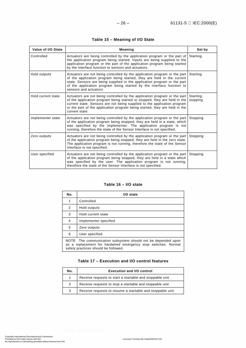
Table 15 – Meaning of I/O State
Value of I/O State Meaning Set by
Controlled Actuators are being controlled by the application program or the part ofthe application program being started. Inputs are being supplied to theapplication program or the part of the application program being startedby the interface function to sensors and actuators.
Starting
Hold outputs Actuators are not being controlled by the application program or the partof the application program being started, they are held in the currentstate. Sensors are being supplied to the application program or the partof the application program being started by the interface function tosensors and actuators.
Starting
Hold current state Actuators are not being controlled by the application program or the partof the application program being started or stopped, they are held in thecurrent state. Sensors are not being supplied to the application programor the part of the application program being started, they are held in thecurrent state.
Starting,stopping
Implementer state Actuators are not being controlled by the application program or the partof the application program being stopped, they are held in a state, whichwas specified by the implementer. The application program is notrunning, therefore the state of the Sensor Interface is not specified.
Stopping
Zero outputs Actuators are not being controlled by the application program or the partof the application program being stopped, they are held in the zero state.The application program is not running, therefore the state of the SensorInterface is not specified.
Stopping
User specified Actuators are not being controlled by the application program or the partof the application program being stopped, they are held in a state whichwas specified by the user. The application program is not running,therefore the state of the Sensor Interface is not specified.
Stopping
Table 16 – I/O state
No. I/O state
1 Controlled
2 Hold outputs
3 Hold current state
4 Implementer specified
5 Zero outputs
6 User specified
NOTE The communication subsystem should not be depended uponas a replacement for hardwired emergency stop switches. Normalsafety practices should be followed.
Table 17 – Execution and I/O control features
No. Execution and I/O control
1 Receive requests to start a startable and stoppable unit
2 Receive requests to stop a startable and stoppable unit
3 Receive requests to resume a startable and stoppable unit
Copyright International Electrotechnical Commission Provided by IHS under license with IEC Licensee=Technip Abu Dabhi/5931917101
Not for Resale, 02/12/2006 07:02:40 MSTNo reproduction or networking permitted without license from IHS
--``,`,`,,,``````,,``,,``,,,,`,-`-`,,`,,`,`,,`---

61131-5 IEC:2000(E) – 27 –
6.2.7 Application program transfer
The application program is transferred using the application program storage and data storagefunction of a PC (see 5.2). Application program transfer allows the client to upload thecomplete contents of the programmable memory or portions thereof for archiving or verificationor to download it for restoring the PC to a known state. This function also provides the ability toplace the PC in a safe state before modifying the contents of its programmable memory, andrestarting it in a safe manner when the application program transfer is completed.
The initiation of the program transfer is typically done by a device that is not a PC. Theservices include:
a) upload for archive;
b) upload for verification;
c) download for restore to previously known good system; and
d) download an off-line developed system.
The portions of the programmable memory which can be uploaded or downloaded are given intable 18.
NOTE A load unit contains the variable P_DDATE, their value is the date of the last modification of the load unit.
Table 18 – Loadable units
No. Loadable units
1 Configuration
2 Resource
3 Programs
4 Global variables
5 Access paths on configuration level
6 Access paths on program level
7 Load units contain the variable P_DDATE
The implementer shall specify if other language elements, for example, function types orfunction block types are loadable and the conditions and restrictions for downloading anduploading these.
This part of IEC 61131 defines a means to perform uploads and downloads on the whole PC, asubsystem of the PC and a portion of a subsystem. The whole or the portion of the PC to bedownloaded shall be explicitly stopped before the download. The whole or the portion of thesystem being downloaded shall not be available for other uses until the download is completed.The implementer shall specify what other clients can do with a PC when one client isdownloading it.
Table 19 – Application program transfer features
No. Application program transfer
1 Receive requests to download a loadable unit
2 Receive requests to upload a loadable unit
Copyright International Electrotechnical Commission Provided by IHS under license with IEC Licensee=Technip Abu Dabhi/5931917101
Not for Resale, 02/12/2006 07:02:40 MSTNo reproduction or networking permitted without license from IHS
--``,`,`,,,``````,,``,,``,,,,`,-`-`,,`,,`,`,,`---

– 28 – 61131-5 IEC:2000(E)
6.2.8 Connection management
The Connection Management provides the means to install, to maintain and close commu-nications connections to a remote communication partner. If multiple requests are initiated tooperate with a device, they may all work over the same connection. Not all communicationssubsystems require connections, for example, point-to-point communication.
Connections are controlled explicitly by the application program using the CONNECT functionblock or are provided by the communication subsystem if and when needed.
Table 20 – Connection management features
No. Connection management
1 Install connections
2 Close connections
3 Using one connection for multiple requests
7 PC communication function blocks
7.1 Overview of the communication function blocks
The following PC communication functions and their corresponding function blocks aredescribed below.
Table 21 – Overview of the communication function blocks
No. Subclause Name of communication functionblock or function
1 7.2 Semantic of communication FB parameters(addressing of remote variables)
REMOTE_VAR
23
7.3 Device verification STATUS,USTATUS
4 7.4 Polled data acquisition READ,
56
78
7.5 Programmed data acquisition USEND,URCV,
BSEND,BRCV
9 7.6 Parametric control WRITE,
1011
7.7 Interlocked control SEND,RCV
1213
7.8 Programmed alarm report NOTIFY,ALARM
14 7.9 Connection management CONNECT
The numbers given in the above table shall be used to state compliance to thesecommunication function blocks (CFB).
7.1.1 Device verification
The STATUS and USTATUS function blocks are provided so that the PC can collect statusfrom other devices. These are provided to allow the PC to determine if the other devices areable to perform their intended function in the automated system.
Copyright International Electrotechnical Commission Provided by IHS under license with IEC Licensee=Technip Abu Dabhi/5931917101
Not for Resale, 02/12/2006 07:02:40 MSTNo reproduction or networking permitted without license from IHS
--``,`,`,,,``````,,``,,``,,,,`,-`-`,,`,,`,`,,`---

61131-5 IEC:2000(E) – 29 –
7.1.2 Data acquisition
Data contained in other devices may be presented as variables. This data may come from avariety of sources and may have a wide range of meanings. It can be obtained by the PCthrough one of two methods using communication function blocks.
a) Polled – The PC uses the READ function block to obtain the value of one or more variablesat a time or condition determined by the PC application program. The access to thevariables may be controlled by the device being read.
b) Programmed – The data is provided to the PC at a time or condition determined by theother device. The PC uses the URCV function block to provide the data to the PCapplication program. The PC uses the USEND to provide unsolicited data to other devices.
The conditions (size, location, etc.) under which each data type supported by the other devicecan be uninterruptedly accessed is determined by the other device.
7.1.3 Control
Two methods of control shall be supported by PCs: parametric and interlocked.
Parametric control is when the operation of the other device is directed by writing values tovariables residing in it. The access to the variables may be controlled by the PC which holdsthe variables. The PC uses the WRITE function block to perform this action from the PCapplication program.
Interlocked control is when the client requests the server to execute an application operationand to inform the client of the result of the operation. The PC uses the SEND and RCV functionblocks to implement the client and server roles, respectively.
7.1.4 Alarm reporting
The PC can have the ability to signal alarm messages to a client when a predeterminedcondition occurs. The client may indicate an acknowledgement of these alarms to the PC. TheALARM and NOTIFY function blocks are used by the PC application program to generateacknowledged and unacknowledged alarms, respectively.
7.1.5 Connection management
The PC application program uses the CONNECT function block to manage connections.
7.2 Semantic of communication FB parameters
The communication function blocks use a common semantic of their function block inputs andoutputs. The meaning of these inputs and outputs is described below. Some communicationfunction blocks have special input or output parameters, they are described where thecommunication function blocks themselves are described.
Copyright International Electrotechnical Commission Provided by IHS under license with IEC Licensee=Technip Abu Dabhi/5931917101
Not for Resale, 02/12/2006 07:02:40 MSTNo reproduction or networking permitted without license from IHS
--``,`,`,,,``````,,``,,``,,,,`,-`-`,,`,,`,`,,`---

– 30 – 61131-5 IEC:2000(E)
Table 22 – Semantic of communication FB parameters
Parameter name Data type of the parameter Interpretation
EN_R BOOL Enabled to receive data
REQ/RESP BOOL Perform function on raising edge
ID COMM_CHANNEL Identification of the communication channel
R_ID STRING Identification of the remote FB inside the channel
SD_i ANY User data to send
VAR_i STRING ordata type of the output of the functionREMOTE_VAR
Identification of a variable of the remotecommunication partner
DONE BOOL Requested function performed (good and valid)
NDR BOOL New user data received (good and valid)
ERROR BOOL New non-zero status received
STATUS INT Last detected status (error or good)
RD_i ANY Last received user data
The ID input references the communication channel used by the instance of the communicationfunction block, i.e. it determines the remote communication partner. The ID input is ofCOMM_CHANNEL type which shall be implementer defined.
NOTE The value given at the ID input of a communication function block instance is intended to hold or referencethe information which is necessary to manage the communication to the remote communication partner. Thisinformation may be dependent on the implementation and the communication subsystem used.
The R_ID input is used to identify the corresponding instance of the communication functionblock at the remote partner, if the PC communication function is provided by a correspondingpair of function block instances.
One instance of a communication function block shall use the same communication channeland communicate to the same corresponding remote function block instance throughout itswhole lifetime.
The variables to be read or written are identified using the VAR_i inputs of the READ andWRITE function blocks. The actual parameter is typically a string which contains the name ofthe remote variable.
Additionally the VAR_i parameter may also have an implementer defined data type namedVAR_ADDR. A function REMOTE_VAR is defined to generate the access information fornested variables.
Copyright International Electrotechnical Commission Provided by IHS under license with IEC Licensee=Technip Abu Dabhi/5931917101
Not for Resale, 02/12/2006 07:02:40 MSTNo reproduction or networking permitted without license from IHS
--``,`,`,,,``````,,``,,``,,,,`,-`-`,,`,,`,`,,`---

61131-5 IEC:2000(E) – 31 –
+--------------+ | REMOTE_VAR | SCOPES ---| SCOPE |--- VAR_ADDR STRING ---| SC_ID | STRING ---| NAME | (Note) ---| SUB | +--------------+FUNCTION REMOTE_VAR (* Generate remote variable address *) : VAR_ADDR; (* Data which may be used at *) (* VAR_i inputs of the READ and *) (* WRITE function blocks *) VAR_INPUT SCOPE : INT; (* Scope of the variable *) SC_ID : STRING; (* Identifier of the name scope *) NAME : STRING; (* Name of the variable *) SUB : (Note); END_VAR
NOTE The input SUB can be of type STRING, or ANY_INT.
Figure 9 – Function REMOTE_VAR
SCOPE is an integer which identifies the name scopes of the programming languages ofIEC 61131-3, the communication system, or the implementer supports as scope of a remotevariable.
Table 23 – Values of the SCOPE parameter
Name scope of IEC 61131-3 Value
Configuration 0
Resource 1
Program 2
Function block instance 3
Reserved for future standardization 4 .. 9
Reserved for name scopes specific to communicationsubsystems
10 .. 99
Implementer specific <0, > 99
If the SCOPE of the variable requires an identifier, the SC_ID is used to supply that identifier.NAME contains the name of the remote variable. If SUB is of string type, the value of the stringis interpreted as a sub-element name. If SUB is an ANY_INT, the value is interpreted as anindex. If SUB is an empty string, the complete variable is addressed.
The data type of the function output is implementer defined. The result of the function may bepassed to the VAR_i inputs of the READ and WRITE function block or may be stored in avariable of the same data type. The use of the REMOTE_VAR function may be restricted onlyto produce valid values for the VAR_i parameters of the READ and WRITE function blocks.
There may be additional functions to support the communication subsystem specific orimplementer specific addressing schemes which produce an output of VAR_ADDR type. Thecommunication subsystem specific functions are specified in the mapping annexes of this partof IEC 61131.
All parameters of the communication function blocks are mandatory except the extensibleparameters SD_i, RD_i, and VAR_i depending on the function block type. It is not requested
IEC 2255/2000
Copyright International Electrotechnical Commission Provided by IHS under license with IEC Licensee=Technip Abu Dabhi/5931917101
Not for Resale, 02/12/2006 07:02:40 MSTNo reproduction or networking permitted without license from IHS
--``,`,`,,,``````,,``,,``,,,,`,-`-`,,`,,`,`,,`---

– 32 – 61131-5 IEC:2000(E)
that the SD_i or RD_i parameters have the same data type if more than one SD_i parameter isused at one function block instance or if an SD_i parameter is used with different functionblock instances. The implementer shall specify the number of SD_i, RD_i, and VAR_iparameters which are supported with one invocation of a communication function block.Additionally, he shall describe if there are restrictions with the use of these parameters, forexample data type or size of the actual parameters.
If a communication function block requests that data types are compatible, the compatibilitycheck shall always be true if the same IEC 61131-3 data types are used at a client PC and aserver PC. Additional communication subsystem specific compatibility rules may be defined.
The outputs are initialized with system zero. NDR, DONE, and ERROR pulse true until the nextinvocation of this instance. That is, each of the communication function blocks implies thefollowing structure, which is not shown in the state diagrams of those function blocks.
All inputs
R_TRIGNDR / DONE
ERROR
STATUS
Communicationfunctionblock
described inthe followingsections
CLK Q
R_TRIG
CLK Q
TRIG2
TRIG1
IEC 2256/2000
Figure 10 – Principle of status signalling
If a communication error of an instance of a communication function block is detected by thePC system or by the algorithm of the communication function block, the ERROR and theSTATUS output of the function block instance are set. The ERROR output remains true duringthe time between two invocations of this instance (see figure 11).
Communication function block:
errors detected --------|--------------|----------------|-------|-----------
ERROR +-----+ +-----+ +-----------+ --------+ +-----------+ +-----------+ +---
STATUS output set --------!-----------------!-----------------!-----!---------
--------^-----^-----^-----^-----^-----^-----^-----^-----^--- instance invocations
Figure 11 – Timing diagram of the ERROR and STATUS outputs
The NDR, DONE, ERROR and the STATUS output shall be set to new values onlysynchronously to the instance invocations of the communication function blocks, even if anerror is detected in between.
IEC 2257/2000
Copyright International Electrotechnical Commission Provided by IHS under license with IEC Licensee=Technip Abu Dabhi/5931917101
Not for Resale, 02/12/2006 07:02:40 MSTNo reproduction or networking permitted without license from IHS
--``,`,`,,,``````,,``,,``,,,,`,-`-`,,`,,`,`,,`---

61131-5 IEC:2000(E) – 33 –
The following values for the STATUS output of the various function blocks have been defined.Not all values are used by all function blocks.
Table 24 – Value and interpretation of the STATUS output
STATUSvalue Interpretation
0 No error
1 Error of lower layers, no communication possible
2 Other negative response from remote communicationpartner
3 R_ID does not exist in the communication channel
4 Data type mismatch
5 Reset received
6 Receiver not enabled
7 Remote communication partner in wrong state
8 Access denied to remote object
9 Receiver overrun (user data are new)
10 Access to local object rejected
11 Requested service exceeds local resources
12 .. 20 Reserved for future standardization
–1 Instance of this function is busy and cannot provideadditional services at this time
< –1 or > 20 Codes less than –1 or greater than 20 are to be specifiedby the implementer
If errors are received from one or more communication partners in the case of one-to-many orone-to-all communication, the STATUS parameter is set according to the first error received.
The RD_i parameters shall contain the received data. These parameters shall be input/outputparameters.
The following subclauses contain a description of the communication function blocks. Therepresentation of the function blocks is given in a graphical and a textual way, and the typesand the meanings of the associated inputs and outputs are shown. The STATUS output shalltake on the appropriate value as defined.
The normal operation is illustrated by a timing diagram.
The operation of the function blocks is described based on state diagrams. The transitionsdepending on the application program are mapped onto conditions of the function block inputs.The transitions depending on the communication system are described independent of thecommunication system used. The explicit mappings to certain communication systems isdescribed in the annexes. The value of the function block outputs are given for each state ofthe state diagram.
Errors caused by the communication system or by local problems may occur asynchronously inall states of a communication function block. Only those errors are explicitly described in thestate diagrams which cause state transitions or require actions. Otherwise, the errors shall onlybe signalled to the application program using the ERROR and STATUS outputs as shown infigures 10 and 11.
Copyright International Electrotechnical Commission Provided by IHS under license with IEC Licensee=Technip Abu Dabhi/5931917101
Not for Resale, 02/12/2006 07:02:40 MSTNo reproduction or networking permitted without license from IHS
--``,`,`,,,``````,,``,,``,,,,`,-`-`,,`,,`,`,,`---

– 34 – 61131-5 IEC:2000(E)
The communication function blocks need to be initialized. The initialization state INIT containedin all state diagrams shall be left at least before the return of the first invocation of the functionblock instance. In this state, all actions shall be done to enable communication. Thecommunication channel to the remote communication partner shall be established, if theconnection management of the channel is not explicitly programmed.
7.3 Device verification
The PC communication function device verification uses the STATUS and the USTATUSfunction blocks.
One instance of a STATUS or USTATUS function block provides one instance of the PCfunction device verification.
A PC can request a remote communication partner to send back to it its status informationusing the STATUS function block.
A PC can itself enable to receive status information of a remote communication partner using theUSTATUS function block. The remote communication partner shall at least inform the USTATUSinstance whenever its status information presented in the PHYS and LOG output changes.
The FB output PHYS contains the physical status of the remote device, the FB output LOGcontains its logical communication status. The FB output LOCAL may contain additional statusinformation up to 128 bits. The implementer shall specify the used length of this additionalstatus information and shall define the semantics of it.
NOTE The READ function block can be used to obtain additional status information.
The ID parameter identifies the communication channel to the remote communication partner.
If an error occurred, the ERROR output pulses one cycle to indicate an error and the STATUSoutput contains the error code.
+-------------+ | STATUS | BOOL ---> REQ NDR |--- BOOL COMM_CHANNEL ---| ID ERROR |--- BOOL | STATUS |--- INT | PHYS |--- INT | LOG |--- INT | LOCAL |--- ARRAY[0..7] OF WORD +-------------+ FUNCTION_BLOCK STATUS (* Device verification – requester *) VAR_INPUT REQ : BOOL R_EDGE; (* Request *) ID : COMM_CHANNEL;(* Communication channel *) END_VAR
VAR_OUTPUT NDR : BOOL; (* New user data received *) ERROR : BOOL; (* New non-zero STATUS received *) STATUS: INT; (* Last detected status *) PHYS : INT; (* Physical status of remote *) (* communication partner *) LOG : INT; (* Logical status of remote *) (* communication partner *) LOCAL : ARRAY[0..7] OF WORD; (* Local status of remote *) END_VAR (* communication partner *)
Figure 12 – STATUS function block
IEC 2258/2000
Copyright International Electrotechnical Commission Provided by IHS under license with IEC Licensee=Technip Abu Dabhi/5931917101
Not for Resale, 02/12/2006 07:02:40 MSTNo reproduction or networking permitted without license from IHS
--``,`,`,,,``````,,``,,``,,,,`,-`-`,,`,,`,`,,`---

61131-5 IEC:2000(E) – 35 –
+-------------+ | USTATUS | BOOL ---| EN_R NDR |--- BOOL COMM_CHANNEL ---| ID ERROR |--- BOOL | STATUS |--- INT | PHYS |--- INT | LOG |--- INT | LOCAL |--- ARRAY[0..7] OF WORD +-------------+ FUNCTION_BLOCK USTATUS (* Device verification – receiver *) VAR_INPUT EN_R : BOOL; (* Enable to receive data *) ID : COMM_CHANNEL;(* Communication channel *) END_VAR
VAR_OUTPUT NDR : BOOL; (* New user data received *) ERROR : BOOL; (* New non-zero STATUS received *) STATUS: INT; (* Last detected status *) PHYS : INT; (* Physical status of remote *) (* communication partner *) LOG : INT; (* Logical status of remote *) (* communication partner *) LOCAL : ARRAY[0..7] OF WORD; (* Local status of remote *) (* communication partner *) END_VAR
Figure 13 – USTATUS function block
Requester's STATUS block: +---------------+ REQ | | ----+ +------------------------------------ t0 t1
+--------+ NDR | | ----------------+ +-------------------------------- t2 t3 TIMING RELATIONSHIPS: t1 > t0 t2 = t0 + tAD + tX (Accept delay and transmit time) t3 = t2 + tNC (Time to next invocation) EVENT IDENTIFICATION: t0: Request of read status information from remote communication partner t1: Requester resets STATUS.REQ input t0..t2: Remote status information is sent to requester t2: Transmission complete, requester's outputs contain the received status information t3: Next invocation of this function block instance
Figure 14 – Timing diagram of the STATUS function block
The state diagram shown in figure 15 describes the algorithm of the STATUS function block.Tables 25 and 26 describe the transitions of this state diagram and the actions to be performedwithin the states and the settings of the STATUS function block outputs.
IEC 2259/2000
IEC 2260/2000
Copyright International Electrotechnical Commission Provided by IHS under license with IEC Licensee=Technip Abu Dabhi/5931917101
Not for Resale, 02/12/2006 07:02:40 MSTNo reproduction or networking permitted without license from IHS
--``,`,`,,,``````,,``,,``,,,,`,-`-`,,`,,`,`,,`---
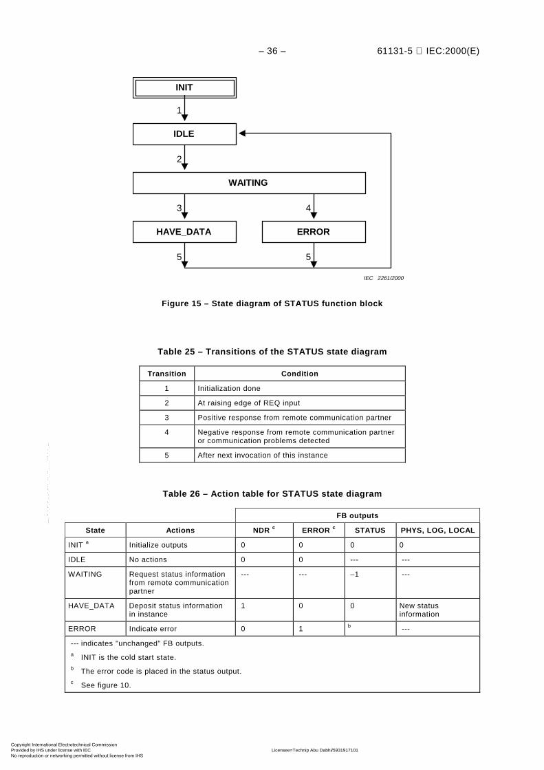
– 36 – 61131-5 IEC:2000(E)
1
INIT
2
3 4
5 5
IDLE
WAITING
HAVE_DATA ERROR
IEC 2261/2000
Figure 15 – State diagram of STATUS function block
Table 25 – Transitions of the STATUS state diagram
Transition Condition
1 Initialization done
2 At raising edge of REQ input
3 Positive response from remote communication partner
4 Negative response from remote communication partneror communication problems detected
5 After next invocation of this instance
Table 26 – Action table for STATUS state diagram
FB outputs
State Actions NDR c ERROR c STATUS PHYS, LOG, LOCAL
INIT a Initialize outputs 0 0 0 0
IDLE No actions 0 0 --- ---
WAITING Request status informationfrom remote communicationpartner
--- --- –1 ---
HAVE_DATA Deposit status informationin instance
1 0 0 New statusinformation
ERROR Indicate error 0 1 b ---
--- indicates "unchanged" FB outputs.a INIT is the cold start state.b The error code is placed in the status output.c See figure 10.
Copyright International Electrotechnical Commission Provided by IHS under license with IEC Licensee=Technip Abu Dabhi/5931917101
Not for Resale, 02/12/2006 07:02:40 MSTNo reproduction or networking permitted without license from IHS
--``,`,`,,,``````,,``,,``,,,,`,-`-`,,`,,`,`,,`---

61131-5 IEC:2000(E) – 37 –
The state diagram of figure 16 describes the algorithm of the USTATUS function block.Tables 27 and 28 describe the transitions of this state diagram and the actions to be performedwithin the states and the settings of the USTATUS function block outputs.
1
INIT
2
4 5
6 6
HAVE_DATA ERROR
ENABLED
DISABLED
3
IEC 2262/2000
Figure 16 – State diagram of USTATUS function block
Table 27 – Transitions of USTATUS state diagrams
Transition Condition
1 Initialization done
2 EN_R = 1
3 EN_R = 0
4 Status information received from remote communicationpartner
5 Communication problems detected
6 After next invocation of this instance
Table 28 – Action table of USTATUS state diagram
FB outputs
State Actions NDR c ERROR c STATUS PHYS, LOG, LOCAL
INIT a Initialize outputs 0 0 0 0
DISABLED No actions 0 0 --- ---
ENABLED No actions 0 0 --- ---
HAVE_DATA Deposit statusinformation
1 0 0 New statusinformation
ERROR Indicate error 0 1 b ---
--- indicates "unchanged" FB outputs.a INIT is the cold start state.b The error code is placed in the status output.c See figure 10.
Copyright International Electrotechnical Commission Provided by IHS under license with IEC Licensee=Technip Abu Dabhi/5931917101
Not for Resale, 02/12/2006 07:02:40 MSTNo reproduction or networking permitted without license from IHS
--``,`,`,,,``````,,``,,``,,,,`,-`-`,,`,,`,`,,`---

– 38 – 61131-5 IEC:2000(E)
7.4 Polled data acquisition
The PC communication function polled data acquisition uses the READ function block.
One instance of a READ function block provides one instance of the PC function polled dataacquisition.
The ID parameter identifies the communication channel to the remote communication partner.
The VAR_i inputs of the READ function block contain a string which can be interpreted by theremote communication partner as variable identifier. The remote communication partner sendsthe values of these variables back to the requesting READ instance. The READ passes thereceived variable values to its application program via its RD_i outputs. Each requestedvariable of the remote communication partner shall have a compatible data type to the variableprogrammed at the RD_i outputs of the READ instance. The VAR_i and RD_i parameters areextensible. At least VAR_1 and RD_1 shall be present.
If the remote communication partner is a PC, variables with an access path and variables withdirect representation may be accessed with a READ function block. The variables with anaccess path are referenced in the VAR_ACCESS construction of the PC programminglanguages (see 2.7.1 of IEC 61131-3). The access name specified in this construction shall beused as the identifier of the variable in the VAR_i input. If a variable with direct representationshall be accessed with a READ function block, the VAR_i input shall contain the directrepresentation, for example %IW17, as a string. It shall be possible to mix the access tovariables with an access path and with direct representation in one invocation of a READfunction block instance.
If a variable shall be read via an access path, which is declared inside a program (see 2.5.3 ofIEC 61131-3) the REMOTE_VAR function shall be used. The name of the program instanceshall be used at the SC_ID input, the name of the variable at the NAME input, for example toread the variable AB12 in the program DO7 the REMOTE_VAR function shall be invoked withREMOTE_VAR (2, "DO7", "AB12", "").
If a sub-element of a structured variable or an element of an array shall be read, the SUB inputof the REMOTE_VAR function shall be used to identify this sub-element or element in theVAR_i inputs.
If an error occurred, the ERROR output pulses one cycle to indicate an error and the STATUSoutput contains the error code.
Copyright International Electrotechnical Commission Provided by IHS under license with IEC Licensee=Technip Abu Dabhi/5931917101
Not for Resale, 02/12/2006 07:02:40 MSTNo reproduction or networking permitted without license from IHS
--``,`,`,,,``````,,``,,``,,,,`,-`-`,,`,,`,`,,`---

61131-5 IEC:2000(E) – 39 –
+--------------+ | READ | BOOL ---> REQ NDR |--- BOOL COMM_CHANNEL ---| ID ERROR |--- BOOL (Note) ---| VAR_1 STATUS |--- INT : | : RD_1 |--- ANY (Note) ---| VAR_n : | : | RD_n |--- ANY +--------------+ FUNCTION_BLOCK READ (* Polled data acquisition *) VAR_INPUT REQ : BOOL R_EDGE; (* Request *) ID : COMM_CHANNEL;(* Communication channel *) VAR_1 : (Note); (* Identification of the *) : (* requested variables, *) VAR_n : (Note); (* extensible *) END_VAR
VAR_OUTPUT NDR : BOOL; (* New user data received *) ERROR : BOOL; (* New non-zero STATUS received *) STATUS: INT; (* Last detected status *) END_VAR
VAR_IN_OUT RD_1 : ANY; (* Received user data *) : (* extensible and any type *) RD_n : ANY; END_VAR
NOTE The VAR_i inputs are extensible and can be of STRING type or of the VAR_ADDRdata type.
Figure 17 – READ function block
Requester's READ block: +---------------+ REQ | | ----+ +------------------------------------ t0 t1
+--------+ NDR | | ----------------+ +-------------------------------- t2 t3 TIMING RELATIONSHIPS: t1 > t0 t2 = t0 + tAD + tX (Accept delay and transmit time) t3 = t2 + tNC (Time to next invocation) EVENT IDENTIFICATION: t0: Request of read data from the remote communication partner t1: Requester resets READ.REQ input t0..t2: The remote data are sent to receiver's READ.RD output t2: Transmission complete, requester's READ.RD contains the received Data t3: Next invocation of this function block instance
Figure 18 – Timing diagram of READ function block
IEC 2263/2000
IEC 2264/2000
Copyright International Electrotechnical Commission Provided by IHS under license with IEC Licensee=Technip Abu Dabhi/5931917101
Not for Resale, 02/12/2006 07:02:40 MSTNo reproduction or networking permitted without license from IHS
--``,`,`,,,``````,,``,,``,,,,`,-`-`,,`,,`,`,,`---

– 40 – 61131-5 IEC:2000(E)
The state diagram of figure 19 describes the algorithm of the READ function block. Tables 29and 30 describe the transitions of this state diagram and the actions to be performed within thestates and the settings of the READ function block outputs.
1
INIT
2
5 6
7 7
HAVE_DATA ERROR
3 4
IDLE
WAITING
CHECKING
IEC 2265/2000
Figure 19 – State diagram of READ function block
Table 29 – Transitions of the READ state diagram
Transition Condition
1 Initialization done
2 At raising edge of REQ input
3 Positive response from remote communication partner
4 Negative response from remote communication partneror other communication problems detected
5 Data types of RD_i and of received data match
6 Data types of RD_i and of received data do not match
7 After next invocation of this instance
Copyright International Electrotechnical Commission Provided by IHS under license with IEC Licensee=Technip Abu Dabhi/5931917101
Not for Resale, 02/12/2006 07:02:40 MSTNo reproduction or networking permitted without license from IHS
--``,`,`,,,``````,,``,,``,,,,`,-`-`,,`,,`,`,,`---

61131-5 IEC:2000(E) – 41 –
Table 30 – Action table for READ state diagram
FB outputs
State Actions NDR c ERROR c STATUS RD_1..RD..n
INIT a Initialize outputs 0 0 0 System null
IDLE No actions 0 0 --- ---
WAITING Request variables fromremote communicationpartner
0 0 –1 ---
CHECKING Verify data type match 0 0 --- ---
HAVE_DATA Deposit data 1 0 0 New data
ERROR Indicate error 0 1 b ---
--- indicates "unchanged" FB outputs.a INIT is the cold start state.b The error code is placed in the status output.c See figure 10.
7.5 Programmed data acquisition
7.5.1 USEND/URCV function blocks
The PC communication function programmed data acquisition uses the USEND and the URCVfunction blocks.
Corresponding instances of one USEND and one URCV function block provide one instance ofthe PC function programmed data acquisition.
The USEND instance sends data to the URCV instance which may process this data with itsapplication program. When requested the USEND instance takes the data from its SD_i inputsand transmits it to the corresponding URCV instance. Previously received data is overwritten.The URCV instance passes the received data to the application program via its RD_i outputs.This occurs whenever the application program requests its USEND instance to send data. TheURCV instance passes newly received data whenever it gets one. It informs the applicationprogram when new data have arrived. The following data flow diagram illustrates this.
URCV
function block
USEND
function block data flow
IEC 2266/2000
Figure 20 – Programmed data acquisition data flow
The SD_i and RD_i parameters are extensible. At least the SD_1 input at the FB USEND andthe RD_1 output at the FB URCV shall be present. The number and each of the data types ofthe SD_i inputs of the USEND instance and the RD_i outputs of the corresponding URCVinstance shall be compatible.
One USEND instance sends data to one URCV instance; that means, they are correspondinginstances, if the value of the ID parameter references the same communication channel and ifthe value of the R_ID parameters are equal within the scope of this communication channel.
NOTE If the communication system provides communication channels which support one-to-many or one-to-allconnections, these function blocks may be used to program a data acquisition function from one communicationpartner to many.
Copyright International Electrotechnical Commission Provided by IHS under license with IEC Licensee=Technip Abu Dabhi/5931917101
Not for Resale, 02/12/2006 07:02:40 MSTNo reproduction or networking permitted without license from IHS
--``,`,`,,,``````,,``,,``,,,,`,-`-`,,`,,`,`,,`---

– 42 – 61131-5 IEC:2000(E)
If an error occurred, the ERROR output pulses one cycle to indicate an error and the STATUSoutput contains the error code.
+-------------+ | USEND | BOOL ---> REQ DONE |--- BOOL COMM_CHANNEL ---| ID ERROR |--- BOOL STRING ---| R_ID STATUS |--- INT ANY ---| SD_1 | : | : | ANY ---| SD_n | +-------------+ FUNCTION_BLOCK USEND (* Programmed data acquisition *) VAR_INPUT (* requester *) REQ : BOOL R_EDGE; (* Request to send *) ID : COMM_CHANNEL;(* Communication channel *) R_ID : STRING; (* Remote function block *) SD_1 : ANY; (* User data to send *) : (* extensible and any type *) SD_n : ANY; END_VAR
VAR_OUTPUT DONE : BOOL; (* Function performed *) ERROR : BOOL; (* New non-zero STATUS received *) STATUS: INT; (* Last detected status *) END_VAR
Figure 21 – USEND function block
+-------------+ | URCV | BOOL ---| EN_R NDR |--- BOOL COMM_CHANNEL ---| ID ERROR |--- BOOL STRING ---| R_ID STATUS |--- INT | RD_1 |--- ANY | : | : | RD_n |--- ANY +-------------+ FUNCTION_BLOCK URCV (* Programmed data acquisition *) VAR_INPUT (* receiver *) EN_R : BOOL; (* Enable to receive data *) ID : COMM_CHANNEL;(* Communication channel *) R_ID : STRING; (* Remote function block *) END_VAR
VAR_OUTPUT NDR : BOOL; (* New user data received *) ERROR : BOOL; (* New non-zero STATUS received *) STATUS: INT; (* Last detected status *) END_VAR
VAR_IN_OUT RD_1 : ANY; (* Received user data *) : (* extensible and any type *) RD_n : ANY; END_VAR
Figure 22 – URCV function block
IEC 2267/2000
IEC 2268/2000
Copyright International Electrotechnical Commission Provided by IHS under license with IEC Licensee=Technip Abu Dabhi/5931917101
Not for Resale, 02/12/2006 07:02:40 MSTNo reproduction or networking permitted without license from IHS
--``,`,`,,,``````,,``,,``,,,,`,-`-`,,`,,`,`,,`---
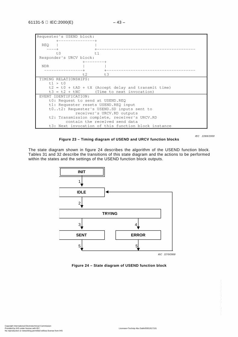
61131-5 IEC:2000(E) – 43 –
Requester's USEND block: +---------------+ REQ | | ----+ +----------------------------------------- t0 t1 Responder's URCV block: +--------+ NDR | | ----------------+ +------------------------------------- t2 t3 TIMING RELATIONSHIPS: t1 > t0 t2 = t0 + tAD + tX (Accept delay and transmit time) t3 = t2 + tNC (Time to next invocation) EVENT IDENTIFICATION: t0: Request to send at USEND.REQ t1: Requester resets USEND.REQ input t0..t2: Requester's USEND.SD inputs sent to receiver's URCV.RD outputs t2: Transmission complete, receiver's URCV.RD contain the received send data t3: Next invocation of this function block instance
Figure 23 – Timing diagram of USEND and URCV function blocks
The state diagram shown in figure 24 describes the algorithm of the USEND function block.Tables 31 and 32 describe the transitions of this state diagram and the actions to be performedwithin the states and the settings of the USEND function block outputs.
1
INIT
2
3 4
5 5
ERRORSENT
IDLE
TRYING
IEC 2270/2000
Figure 24 – State diagram of USEND function block
IEC 2269/2000
Copyright International Electrotechnical Commission Provided by IHS under license with IEC Licensee=Technip Abu Dabhi/5931917101
Not for Resale, 02/12/2006 07:02:40 MSTNo reproduction or networking permitted without license from IHS
--``,`,`,,,``````,,``,,``,,,,`,-`-`,,`,,`,`,,`---

– 44 – 61131-5 IEC:2000(E)
Table 31 – Transitions of the USEND state diagram
Transition Condition
1 Initialization done
2 At raising edge of REQ input
3 Communication system indicates "Sent to RemoteCommunication Partner"
4 Communication system indicates "Cannot Send toRemote Communication Partner" or other communicationproblems detected
5 After next invocation of this instance
Table 32 – Action table for USEND state diagram
FB outputs
State Actions DONE c ERROR c STATUS
INIT a Initialize outputs 0 0 0
IDLE No actions 0 0 ---
TRYING Send data given at the SD_i inputs toremote communication partner
--- --- ---
SENT Clear error indication 1 0 0
ERROR Indicate error 0 1 b
--- indicates "unchanged" FB outputs.a INIT is the cold start state.b The error code is placed in the status output.c See figure 10.
The state diagram of figure 25 describes the algorithm of the URCV function block. Tables 33and 34 describe the transitions of this state diagram and the actions to be performed within thestates and the settings of the URCV function block outputs.
Copyright International Electrotechnical Commission Provided by IHS under license with IEC Licensee=Technip Abu Dabhi/5931917101
Not for Resale, 02/12/2006 07:02:40 MSTNo reproduction or networking permitted without license from IHS
--``,`,`,,,``````,,``,,``,,,,`,-`-`,,`,,`,`,,`---

61131-5 IEC:2000(E) – 45 –
1
INIT
2
6 7
8 8
HAVE_DATA ERROR
4 5
DISABLED
ENABLED
CHECKING
3
IEC 2271/2000
Figure 25 – State diagram of URCV function block
Table 33 – Transitions of URCV state diagrams
Transition Condition
1 Initialization done
2 EN_R = 1
3 EN_R = 0
4 Data received from remote communication partner
5 Communication problems detected
6 Data types of SD_i of USEND and RD_i of URCV match
7 Data types of SD_i of USEND and RD_i of URCV do notmatch
8 After next invocation of this instance
Copyright International Electrotechnical Commission Provided by IHS under license with IEC Licensee=Technip Abu Dabhi/5931917101
Not for Resale, 02/12/2006 07:02:40 MSTNo reproduction or networking permitted without license from IHS
--``,`,`,,,``````,,``,,``,,,,`,-`-`,,`,,`,`,,`---

– 46 – 61131-5 IEC:2000(E)
Table 34 – Action table of URCV state diagram
FB outputs
State Actions NDR c ERROR c STATUS RD_1..RD..n
INIT a Initialize outputs 0 0 0 System null
DISABLED No actions 0 0 --- ---
ENABLED No actions --- --- --- ---
CHECKING Verify data type match --- --- --- ---
HAVE_DATA Deposit data 1 0 0, 9 New data
ERROR Indicate error 0 1 b ---
--- indicates "unchanged" FB outputs.a INIT is the cold start state.b The error code is placed in the status output.c See figure 10.
7.5.2 BSEND / BRCV Function Blocks
Corresponding instances of one BSEND and one BRCV function block provide one instance ofthe PC function programmed data acquisition.
The BSEND instance sends data to the BRCV instance, which may process this data with itsapplication program. When requested the BSEND instance takes the data from its SD_1 inputand transmits it to the corresponding BRCV instance. Previously received data is overwritten.The BRCV instance passes the received data to the application program via its RD_1 output.This occurs when the application program requests its BSEND instance to send data. TheBRCV instance passes newly received data when it has finished its previous request and getsnew data. It informs the application program when new data have arrived.
The SD_1 input of the BSEND instance and the RD_1 output of the BRCV instance shall bothbe of data type ANY and are interpreted as a sequence of bytes.
NOTE The representation of the data in the controller is typically dependent on the implementation. Thecommunication partners shall agree in the interpretation of any data if data of data type other than array of byte aretransferred. This restricts the interoperability of programs using these communication function blocks.
Copyright International Electrotechnical Commission Provided by IHS under license with IEC Licensee=Technip Abu Dabhi/5931917101
Not for Resale, 02/12/2006 07:02:40 MSTNo reproduction or networking permitted without license from IHS
--``,`,`,,,``````,,``,,``,,,,`,-`-`,,`,,`,`,,`---
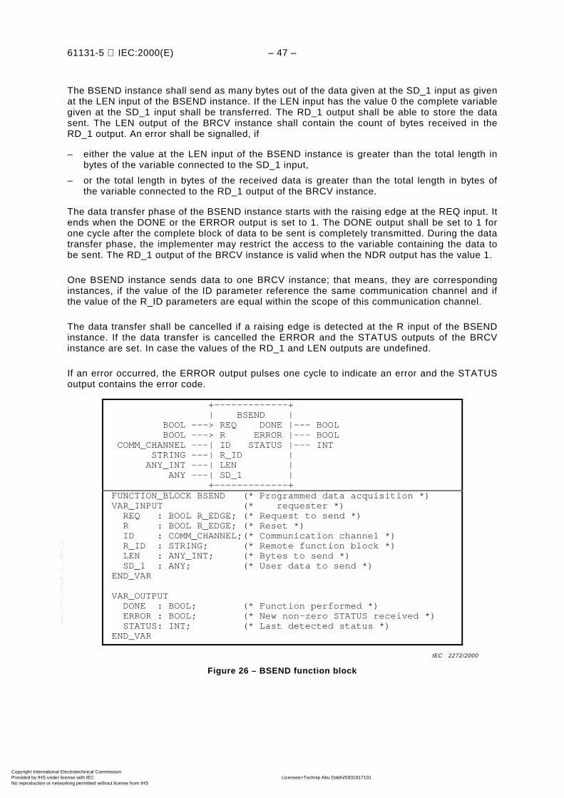
61131-5 IEC:2000(E) – 47 –
The BSEND instance shall send as many bytes out of the data given at the SD_1 input as givenat the LEN input of the BSEND instance. If the LEN input has the value 0 the complete variablegiven at the SD_1 input shall be transferred. The RD_1 output shall be able to store the datasent. The LEN output of the BRCV instance shall contain the count of bytes received in theRD_1 output. An error shall be signalled, if
– either the value at the LEN input of the BSEND instance is greater than the total length inbytes of the variable connected to the SD_1 input,
– or the total length in bytes of the received data is greater than the total length in bytes ofthe variable connected to the RD_1 output of the BRCV instance.
The data transfer phase of the BSEND instance starts with the raising edge at the REQ input. Itends when the DONE or the ERROR output is set to 1. The DONE output shall be set to 1 forone cycle after the complete block of data to be sent is completely transmitted. During the datatransfer phase, the implementer may restrict the access to the variable containing the data tobe sent. The RD_1 output of the BRCV instance is valid when the NDR output has the value 1.
One BSEND instance sends data to one BRCV instance; that means, they are correspondinginstances, if the value of the ID parameter reference the same communication channel and ifthe value of the R_ID parameters are equal within the scope of this communication channel.
The data transfer shall be cancelled if a raising edge is detected at the R input of the BSENDinstance. If the data transfer is cancelled the ERROR and the STATUS outputs of the BRCVinstance are set. In case the values of the RD_1 and LEN outputs are undefined.
If an error occurred, the ERROR output pulses one cycle to indicate an error and the STATUSoutput contains the error code.
+-------------+ | BSEND | BOOL ---> REQ DONE |--- BOOL BOOL ---> R ERROR |--- BOOL COMM_CHANNEL ---| ID STATUS |--- INT STRING ---| R_ID | ANY_INT ---| LEN | ANY ---| SD_1 | +-------------+ FUNCTION_BLOCK BSEND (* Programmed data acquisition *) VAR_INPUT (* requester *) REQ : BOOL R_EDGE; (* Request to send *) R : BOOL R_EDGE; (* Reset *) ID : COMM_CHANNEL;(* Communication channel *) R_ID : STRING; (* Remote function block *) LEN : ANY_INT; (* Bytes to send *) SD_1 : ANY; (* User data to send *) END_VAR
VAR_OUTPUT DONE : BOOL; (* Function performed *) ERROR : BOOL; (* New non-zero STATUS received *) STATUS: INT; (* Last detected status *) END_VAR
Figure 26 – BSEND function block
IEC 2272/2000
Copyright International Electrotechnical Commission Provided by IHS under license with IEC Licensee=Technip Abu Dabhi/5931917101
Not for Resale, 02/12/2006 07:02:40 MSTNo reproduction or networking permitted without license from IHS
--``,`,`,,,``````,,``,,``,,,,`,-`-`,,`,,`,`,,`---

– 48 – 61131-5 IEC:2000(E)
+-------------+ | BRCV | BOOL ---| EN_R NDR |--- BOOL COMM_CHANNEL ---| ID ERROR |--- BOOL STRING ---| R_ID STATUS |--- INT | LEN |--- ANY_INT | RD_1 |--- ANY +-------------+ FUNCTION_BLOCK BRCV (* Programmed data acquisition *) VAR_INPUT (* receiver *) EN_R : BOOL; (* Enable to receive data *) ID : COMM_CHANNEL;(* Communication channel *) R_ID : STRING; (* Remote function block *) END_VAR
VAR_OUTPUT NDR : BOOL; (* New user data received *) ERROR : BOOL; (* New non-zero STATUS received *) STATUS: INT; (* Last detected status *) LEN : ANY_INT; (* Count of received bytes *) END_VAR
VAR_IN_OUT RD_1 : ANY; (* Received user data *) END_VAR
Figure 27 – BRCV function block
Requester's BSEND block: +--------+ REQ | | ----+ +------------------------------------------------ t0 t1
+---+ DONE | | ----------------+ +----------------------------------------- t3 t4
Responder's BRCV block: +--------+ NDR | | ---------------+ +------------------------------------- t2 t5 TIMING RELATIONSHIPS: t1 > t0 t2 = t0 + tAD + tX (Accept delay and transmit time) t3 = t2 + tCF (Confirmation transmit time) t4 = t3 + tNC1 (Time to next invocation) t5 = t2 + tNC2 (Time to next invocation) EVENT IDENTIFICATION: t0: Request to send at BSEND.REQ t1: Requester resets BSEND.REQ input t0..t2: Requester's BSEND.SD inputs sent to receiver's BRCV.RD outputs t2: Transmission of complete data finished, receiver's BRCV.RD contain the received send data t3: Last confirmation received by Requester t4: Next invocation of this function block instance t5: Next invocation of this function block instance
Figure 28 – Timing diagram of BSEND and BRCV function blocks
IEC 2273/2000
IEC 2274/2000
Copyright International Electrotechnical Commission Provided by IHS under license with IEC Licensee=Technip Abu Dabhi/5931917101
Not for Resale, 02/12/2006 07:02:40 MSTNo reproduction or networking permitted without license from IHS
--``,`,`,,,``````,,``,,``,,,,`,-`-`,,`,,`,`,,`---

61131-5 IEC:2000(E) – 49 –
The state diagram shown in figure 29 describes the algorithm of the BSEND function block.Tables 35 and 36 describe the transitions of this state diagram and the actions to be performedwithin the states and the settings of the BSEND function block outputs.
INIT
1
2
6 3
8
9
8
4
5
4
5
3 6 7
SEND_FIRST
IDLE
CANCEL
ERRORSENT
SEND_NEXT
IEC 2275/2000
Figure 29 – State diagram of BSEND function block
Table 35 – Transitions of the BSEND state diagram
Transition Condition
1 Initialization done
2 At raising edge of REQ input
3 Positive confirmation received and more data to send
4 Negative confirmation received or communicationproblems detected
5 At raising edge of R input
6 Positive confirmation received and no more data to send
7 Immediate
8 After next invocation of this instance
9 Communication problems detected
Copyright International Electrotechnical Commission Provided by IHS under license with IEC Licensee=Technip Abu Dabhi/5931917101
Not for Resale, 02/12/2006 07:02:40 MSTNo reproduction or networking permitted without license from IHS
--``,`,`,,,``````,,``,,``,,,,`,-`-`,,`,,`,`,,`---

– 50 – 61131-5 IEC:2000(E)
Table 36 – Action table for BSEND state diagram
FB outputs
State Actions DONE c ERROR c STATUS
INIT a Initialize outputs 0 0 0
IDLE No actions 0 0 ---
SEND_FIRST Send first block of data given at theSD_1 input to remote communicationpartner, send a maximum of LEN bytesin total
--- –1 ---
SEND_NEXT Send next block of data given at theSD_1 input to remote communicationpartner, send a maximum of LEN bytesin total
--- --- ---
SENT Clear error indication 1 0 0
CANCEL Stop the data transfer --- --- ---
ERROR Indicate error 0 1 b
--- indicates "unchanged" FB outputs.a INIT is the cold start state.b The error code is placed in the status output.c See figure 10.
The state diagram shown in figure 30 describes the algorithm of the BRCV function block.Tables 37 and 38 describe the transitions of this state diagram and the actions to be performedwithin the states and the settings of the BRCV function block outputs.
INIT
1
2
5 6
10
8
10
9
7 7
RECEIVING
ENABLED
DISABLED
ERRORHAVE_IT
RESP_LASTRESP_MORE
3
4
RESP_NEG
4
7
CANCELLED
8
7
IEC 2276/2000
Figure 30 – State diagram of BRCV function block
Copyright International Electrotechnical Commission Provided by IHS under license with IEC Licensee=Technip Abu Dabhi/5931917101
Not for Resale, 02/12/2006 07:02:40 MSTNo reproduction or networking permitted without license from IHS
--``,`,`,,,``````,,``,,``,,,,`,-`-`,,`,,`,`,,`---
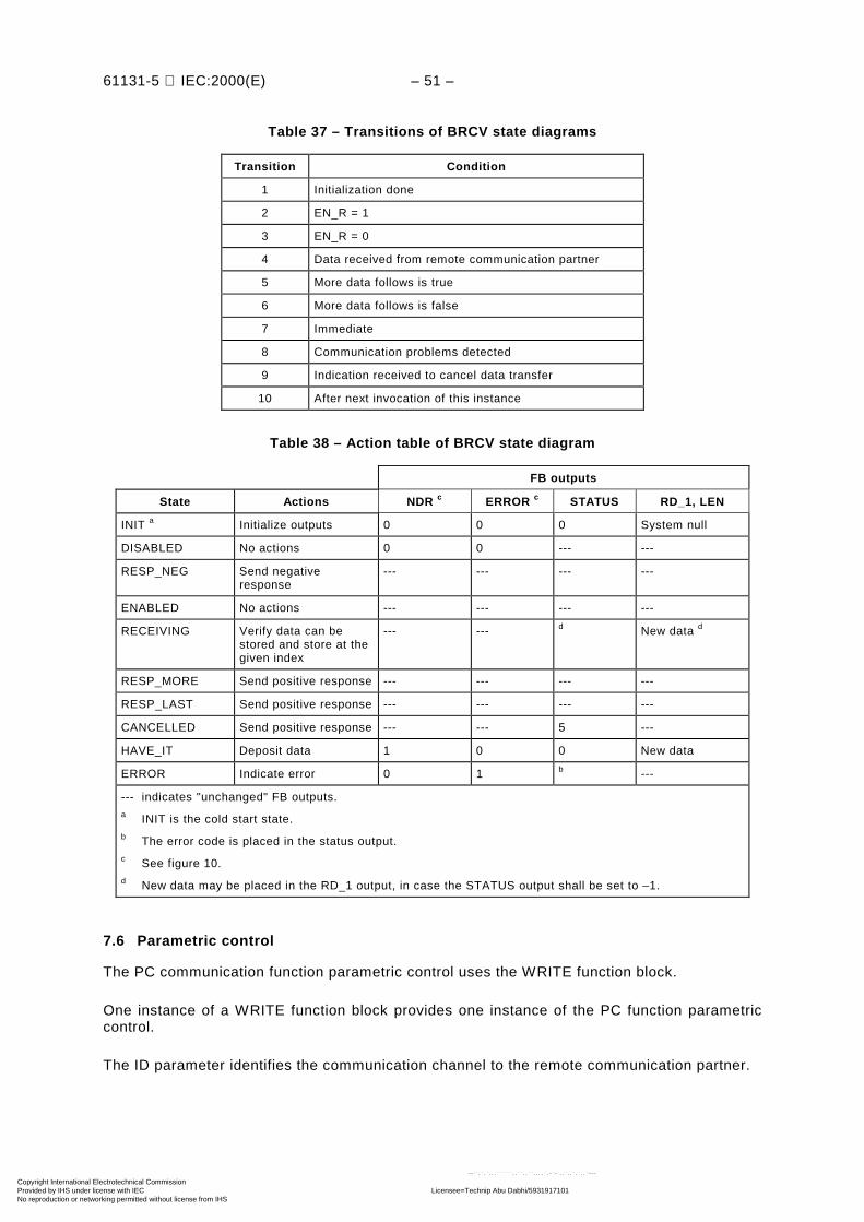
61131-5 IEC:2000(E) – 51 –
Table 37 – Transitions of BRCV state diagrams
Transition Condition
1 Initialization done
2 EN_R = 1
3 EN_R = 0
4 Data received from remote communication partner
5 More data follows is true
6 More data follows is false
7 Immediate
8 Communication problems detected
9 Indication received to cancel data transfer
10 After next invocation of this instance
Table 38 – Action table of BRCV state diagram
FB outputs
State Actions NDR c ERROR c STATUS RD_1, LEN
INIT a Initialize outputs 0 0 0 System null
DISABLED No actions 0 0 --- ---
RESP_NEG Send negativeresponse
--- --- --- ---
ENABLED No actions --- --- --- ---
RECEIVING Verify data can bestored and store at thegiven index
--- --- d New data d
RESP_MORE Send positive response --- --- --- ---
RESP_LAST Send positive response --- --- --- ---
CANCELLED Send positive response --- --- 5 ---
HAVE_IT Deposit data 1 0 0 New data
ERROR Indicate error 0 1 b ---
--- indicates "unchanged" FB outputs.a INIT is the cold start state.b The error code is placed in the status output.c See figure 10.d New data may be placed in the RD_1 output, in case the STATUS output shall be set to –1.
7.6 Parametric control
The PC communication function parametric control uses the WRITE function block.
One instance of a WRITE function block provides one instance of the PC function parametriccontrol.
The ID parameter identifies the communication channel to the remote communication partner.
Copyright International Electrotechnical Commission Provided by IHS under license with IEC Licensee=Technip Abu Dabhi/5931917101
Not for Resale, 02/12/2006 07:02:40 MSTNo reproduction or networking permitted without license from IHS
--``,`,`,,,``````,,``,,``,,,,`,-`-`,,`,,`,`,,`---
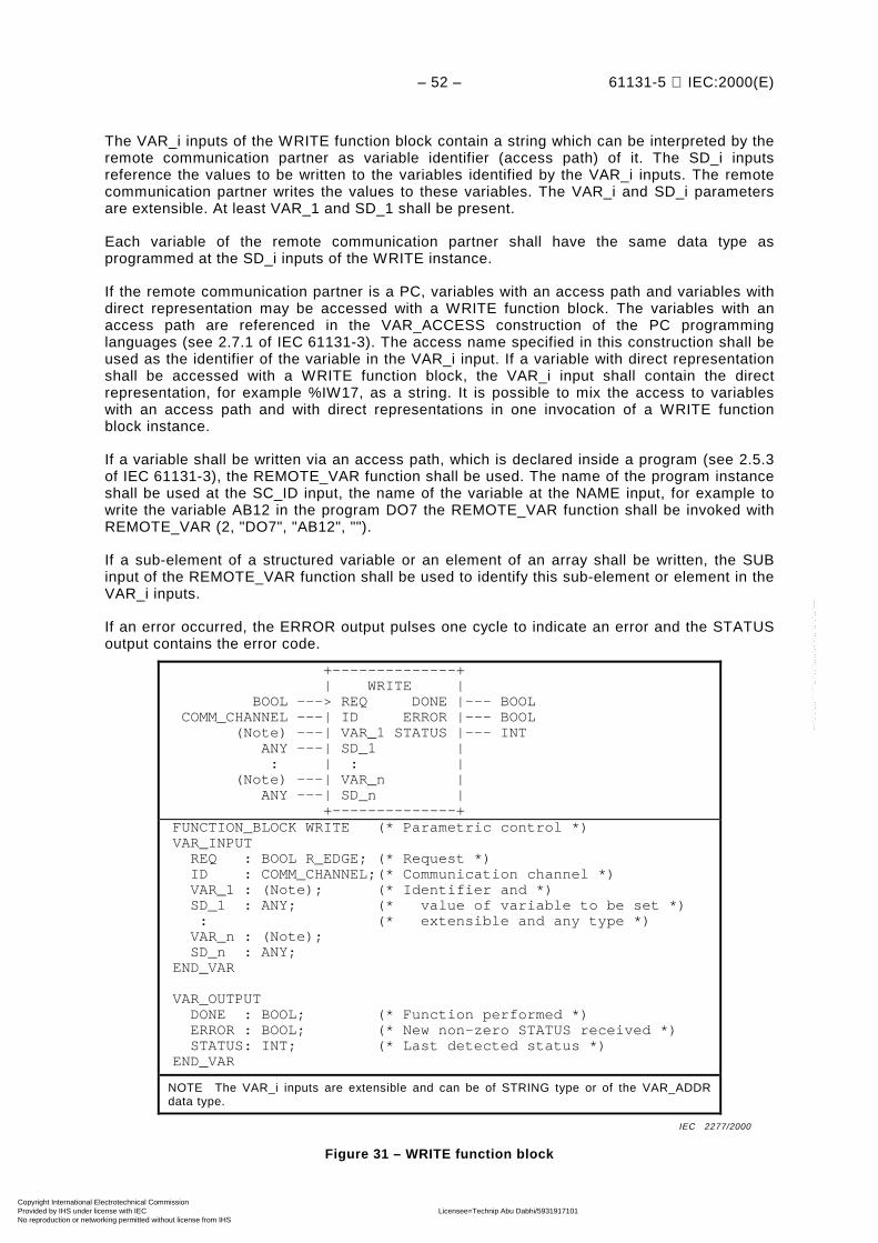
– 52 – 61131-5 IEC:2000(E)
The VAR_i inputs of the WRITE function block contain a string which can be interpreted by theremote communication partner as variable identifier (access path) of it. The SD_i inputsreference the values to be written to the variables identified by the VAR_i inputs. The remotecommunication partner writes the values to these variables. The VAR_i and SD_i parametersare extensible. At least VAR_1 and SD_1 shall be present.
Each variable of the remote communication partner shall have the same data type asprogrammed at the SD_i inputs of the WRITE instance.
If the remote communication partner is a PC, variables with an access path and variables withdirect representation may be accessed with a WRITE function block. The variables with anaccess path are referenced in the VAR_ACCESS construction of the PC programminglanguages (see 2.7.1 of IEC 61131-3). The access name specified in this construction shall beused as the identifier of the variable in the VAR_i input. If a variable with direct representationshall be accessed with a WRITE function block, the VAR_i input shall contain the directrepresentation, for example %IW17, as a string. It is possible to mix the access to variableswith an access path and with direct representations in one invocation of a WRITE functionblock instance.
If a variable shall be written via an access path, which is declared inside a program (see 2.5.3of IEC 61131-3), the REMOTE_VAR function shall be used. The name of the program instanceshall be used at the SC_ID input, the name of the variable at the NAME input, for example towrite the variable AB12 in the program DO7 the REMOTE_VAR function shall be invoked withREMOTE_VAR (2, "DO7", "AB12", "").
If a sub-element of a structured variable or an element of an array shall be written, the SUBinput of the REMOTE_VAR function shall be used to identify this sub-element or element in theVAR_i inputs.
If an error occurred, the ERROR output pulses one cycle to indicate an error and the STATUSoutput contains the error code.
+--------------+ | WRITE | BOOL ---> REQ DONE |--- BOOL COMM_CHANNEL ---| ID ERROR |--- BOOL (Note) ---| VAR_1 STATUS |--- INT ANY ---| SD_1 | : | : | (Note) ---| VAR_n | ANY ---| SD_n | +--------------+ FUNCTION_BLOCK WRITE (* Parametric control *) VAR_INPUT REQ : BOOL R_EDGE; (* Request *) ID : COMM_CHANNEL;(* Communication channel *) VAR_1 : (Note); (* Identifier and *) SD_1 : ANY; (* value of variable to be set *) : (* extensible and any type *) VAR_n : (Note); SD_n : ANY; END_VAR
VAR_OUTPUT DONE : BOOL; (* Function performed *) ERROR : BOOL; (* New non-zero STATUS received *) STATUS: INT; (* Last detected status *) END_VAR
NOTE The VAR_i inputs are extensible and can be of STRING type or of the VAR_ADDRdata type.
Figure 31 – WRITE function block
IEC 2277/2000
Copyright International Electrotechnical Commission Provided by IHS under license with IEC Licensee=Technip Abu Dabhi/5931917101
Not for Resale, 02/12/2006 07:02:40 MSTNo reproduction or networking permitted without license from IHS
--``,`,`,,,``````,,``,,``,,,,`,-`-`,,`,,`,`,,`---

61131-5 IEC:2000(E) – 53 –
Requester's WRITE block: +---------------+ REQ | | ----+ +------------------------------------ t0 t1
+--------+ DONE | | ----------------+ +-------------------------------- t2 t3 TIMING RELATIONSHIPS: t1 > t0 t2 = t0 + tAD + tX (Accept delay and transmit time) t3 = t2 + tNC (Time to next invocation) EVENT IDENTIFICATION: t0: Request to write data at the remote communication partner t1: Requester resets WRITE.REQ input t0..t2: The data (identifiers and values) are sent to the remote communication partner, the variables are set, the acknowledgement is sent back t2: Transmission complete, acknowledgement received t3: Next invocation of this function block instance
Figure 32 – Timing diagram of WRITE function block
The state diagram shown in figure 33 describes the algorithm of the WRITE function block.Tables 39 and 40 describe the transitions of this state diagram and the actions to be performedwithin the states and the settings of the WRITE function block outputs.
1
INIT
2
3 4
5 5
ERROR
IDLE
HAVE_IT
WAITING
IEC 2279/2000
Figure 33 – State diagram of WRITE function block
IEC 2278/2000
Copyright International Electrotechnical Commission Provided by IHS under license with IEC Licensee=Technip Abu Dabhi/5931917101
Not for Resale, 02/12/2006 07:02:40 MSTNo reproduction or networking permitted without license from IHS
--``,`,`,,,``````,,``,,``,,,,`,-`-`,,`,,`,`,,`---

– 54 – 61131-5 IEC:2000(E)
Table 39 – Transitions of the WRITE state diagram
Transition Condition
1 Initialization done
2 At raising edge of REQ input
3 Positive response of remote communication partner
4 Negative response from remote communication partneror other communication problems detected
5 After next invocation of this instance
Table 40 – Action table for WRITE state diagram
FB outputs
State Actions DONE c ERROR c STATUS
INIT a Initialize outputs 0 0 0
IDLE No actions 0 0 ---
WAITING Request to writevariables into remotecommunication partner
--- --- –1
HAVE_IT Indicate success 1 0 0
ERROR Indicate error 0 1 b
--- indicates "unchanged" FB outputs.a INIT is the cold start state.b The error code is placed in the status output.c See figure 10.
7.7 Interlocked control
The PC communication function interlocked control uses the SEND and the RCV function blocks.
Corresponding instances of one SEND and of one RCV function block type provide one PCfunction interlocked control. Two instances of the SEND and RCV function block arecorresponding, if the value of the ID parameters reference the same communication channel andif the value of the R_ID parameters are equal within the scope of this communication channel.
The SEND instance requests the RCV instance to execute an application operation and toinform the SEND instance of the result of the operation. This has two aspects, thesynchronization of the application program of the SEND and RCV instances and the exchangeof information between them. This function can be used to have the effect of a remoteprocedure call from one application program to another.
The interlocked control function is requested by a raising edge of the REQ input of the SENDfunction block instance. When requested the SEND instance takes the data from its SD_iinputs and transmits it to the corresponding RCV instance.
When the EN_R input of the RCV instance has the value of 1, it is enabled to receive data fromthe corresponding SEND instance and to perform the intended operation of the applicationprogram. When the RCV instance receives the data from the SEND instance, it passes thereceived data to the application program via its RD_i outputs. The NDR output of the RCVinstance pulses one cycle to indicate that new data were received. After performing theintended operation of the application program, the result data are taken via the SD_i inputs andthe response is initiated on a raising edge of the RESP input of the RCV instance.
Copyright International Electrotechnical Commission Provided by IHS under license with IEC Licensee=Technip Abu Dabhi/5931917101
Not for Resale, 02/12/2006 07:02:40 MSTNo reproduction or networking permitted without license from IHS
--``,`,`,,,``````,,``,,``,,,,`,-`-`,,`,,`,`,,`---

61131-5 IEC:2000(E) – 55 –
When the SEND instance receives this response, it passes the received data to its RD_ioutputs. The NDR output of the SEND instance pulses one cycle to indicate that new data areready.
A raising edge on the R input of the SEND instance resets both the SEND and thecorresponding RCV instance.
The number and each of the data types of the SD_i inputs of the SEND instance and the RD_ioutputs of the corresponding RCV instance shall be compatible. The same is required for theSD_i inputs of the RCV instance and the RD_i outputs of the SEND instance. The SD_i inputsand the RD_i outputs of the SEND and RCV function blocks are extensible. Either the senddata or the response data or both may be empty, that is, the user did not program any SD_iinputs and corresponding RD_i outputs.
If the received data did not match the RD_i outputs of the RCV function block or an erroroccurred, the ERROR output pulses one cycle to indicate an error and the STATUS outputcontains the error code.
+-------------+ | SEND | BOOL ---> REQ NDR |--- BOOL BOOL ---> R ERROR |--- BOOL COMM_CHANNEL ---| ID STATUS |--- INT STRING ---| R_ID RD_1 |--- ANY ANY ---| SD_1 : | : : | : RD_m |--- ANY ANY ---| SD_n | +-------------+ FUNCTION_BLOCK SEND (* Interlocked control, requester*) VAR_INPUT REQ : BOOL R_EDGE; (* Request to send with raising edge*) R : BOOL R_EDGE; (* Reset local, remote function *) ID : COMM_CHANNEL;(* Communication channel *) R_ID : STRING; (* Remote function block *) SD_1 : ANY; (* User data to send *) : (* extensible and any type *) SD_n : ANY; END_VAR
VAR_OUTPUT NDR : BOOL; (* New user data received *) ERROR : BOOL; (* New non-zero STATUS received *) STATUS: INT; (* Last detected status *) END_VAR
VAR_IN_OUT RD_1 : ANY; (* Received user data *) : (* extensible and any type *) RD_m : ANY; (* It is not required that m = n *) END_VAR (* either m, n, or both may be 0*)
Figure 34 – SEND function block
IEC 2280/2000
Copyright International Electrotechnical Commission Provided by IHS under license with IEC Licensee=Technip Abu Dabhi/5931917101
Not for Resale, 02/12/2006 07:02:40 MSTNo reproduction or networking permitted without license from IHS
--``,`,`,,,``````,,``,,``,,,,`,-`-`,,`,,`,`,,`---

– 56 – 61131-5 IEC:2000(E)
+-------------+ | RCV | BOOL ---| EN_R NDR |--- BOOL BOOL ---> RESP ERROR |--- BOOL COMM_CHANNEL ---| ID STATUS |--- INT STRING ---| R_ID RD_1 |--- ANY ANY ---| SD_1 : | : | : RD_n |--- ANY ANY ---| SD_m | +-------------+ FUNCTION_BLOCK RCV (* Interlocked control, responder*) VAR_INPUT EN_R : BOOL; (* Enable to receive data *) RESP : BOOL R_EDGE; (* Request to send response data *) ID : COMM_CHANNEL;(* Communication channel *) R_ID : STRING; (* Remote function block *) SD_1 : ANY; (* User data to send *) : (* extensible and any type *) SD_m : ANY; END_VAR
VAR_OUTPUT NDR : BOOL; (* New user data received *) ERROR : BOOL; (* New non-zero STATUS received *) STATUS: INT; (* Last detected status *) END_VAR
VAR_IN_OUT RD_1 : ANY; (* Received user data *) : (* extensible and any type *) RD_n : ANY; (* It is not required that m = n *) END_VAR (* either m, n, or both may be 0*)
Figure 35 – RCV function block
IEC 2281/2000
Copyright International Electrotechnical Commission Provided by IHS under license with IEC Licensee=Technip Abu Dabhi/5931917101
Not for Resale, 02/12/2006 07:02:40 MSTNo reproduction or networking permitted without license from IHS
--``,`,`,,,``````,,``,,``,,,,`,-`-`,,`,,`,`,,`---

61131-5 IEC:2000(E) – 57 –
Requester's SEND block: +------+ REQ | | ----+ +--------------------------------------------- t0 t1 +------+ NDR | | ----------------------------------------------+ +--- t6 t7
Responder's RCV block: +------+ NDR | | ----------------+ +---------------------------------- t2 t3 +------------+ RESP | | ------------------------------+ +-------------- t4 t5 TIMING RELATIONSHIPS: t1 > t0 t2 = t0 + tSX (Send transmit time) t3 = t2 + tNI (Time to next invocation) t4 > t2 t5 > t4 t6 = t4 + tRX (Response transmit time) t7 = t6 + tNI (Time to next invocation) EVENT IDENTIFICATION: t0: Request to send at SEND.REQ t1: Requester resets SEND.REQ input t2: Transmission complete, responder's RCV.RD_i contain the received send data t3: Next invocation of RCV instance t4: Responder requests to send RCV.SD_j inputs t5: Responder resets RCV.RESP input t6: Transaction complete, requester's SEND.RD_j contain the received response data t7: Next invocation of the SEND instance
Figure 36 – Timing diagram of SEND and RCV function blocks
IEC 2282/2000
Copyright International Electrotechnical Commission Provided by IHS under license with IEC Licensee=Technip Abu Dabhi/5931917101
Not for Resale, 02/12/2006 07:02:40 MSTNo reproduction or networking permitted without license from IHS
--``,`,`,,,``````,,``,,``,,,,`,-`-`,,`,,`,`,,`---

– 58 – 61131-5 IEC:2000(E)
The state diagram shown in figure 37 describes the algorithm of the SEND function block.Tables 41 and 42 describe the transitions of this state diagram and the actions to be performedwithin the states and the settings of the SEND function block outputs.
2
1010
1
7
3 8
5 6
11
4, 12 12
9, 12
IDLE
SEND_AND_WAIT CANCEL
CHECKING WAIT_RCV
HAVE_DATA ERROR
INIT
9
8, 12
WAIT_CNCL
IEC 2283/2000
Figure 37 – State diagram of SEND function block
Table 41 – Transitions of the SEND state diagram
Transition Condition
1 Initialization done
2 At raising edge of REQ input
3 Positive response from RCV
4 Negative response from RCV
5 Data types of received data and RD_1 to RD_m match
6 Data type of received data and RD_1 to RD_m mismatch
7 At raising edge of R input
8 Positive or negative response to the reset request
9 Positive or negative response from RCV
10 After next invocation of the instance
11 Local resource problems detected
12 Communication problems detected
Copyright International Electrotechnical Commission Provided by IHS under license with IEC Licensee=Technip Abu Dabhi/5931917101
Not for Resale, 02/12/2006 07:02:40 MSTNo reproduction or networking permitted without license from IHS
--``,`,`,,,``````,,``,,``,,,,`,-`-`,,`,,`,`,,`---

61131-5 IEC:2000(E) – 59 –
Table 42 – Action table for SEND state diagram
FB outputs
State Actions NDR c ERROR c STATUS RD_1 ... RD_m
INIT a Initialize outputs 0 0 0 System null
IDLE No actions 0 0 --- ---
SEND_AND_WAIT Send data to RCV, evaluatetransition 7 first
--- --- –1 ---
CHECKING Verify data type match --- --- --- ---
HAVE_DATA Deposit data in instance 1 0 0 New data fromRCV
ERROR Indicate error 0 1 b ---
CANCEL Request to reset RCV --- --- 5 ---
WAIT_RCV No actions --- --- --- ---
WAIT_CNCL No actions --- --- --- ---
--- indicates "unchanged" FB outputs.a INIT is the cold start state.b The error code is placed in the status output.c See figure 10.
Copyright International Electrotechnical Commission Provided by IHS under license with IEC Licensee=Technip Abu Dabhi/5931917101
Not for Resale, 02/12/2006 07:02:40 MSTNo reproduction or networking permitted without license from IHS
--``,`,`,,,``````,,``,,``,,,,`,-`-`,,`,,`,`,,`---

– 60 – 61131-5 IEC:2000(E)
The state diagram shown in figure 38 describes the algorithm of the RCV function block.Tables 43 and 44 describe the transitions of this state diagram and the actions to be performedwithin the states and the settings of the RCV function block outputs.
5
11
412
3
7 8 9
11 11
9, 10
12
3
12
4
4
6
9, 10
12
10
RESPONDING ERROR
NAK_CANCELED
WAITING12
HAVE_DATA
NAK_DIS CHECKING
ENABLEDDISABLED
NAK_ERROR
NAK_BUSY
INIT
IEC 2284/2000
Figure 38 – State diagram of RCV function block
Table 43 – Transitions of RCV state diagrams
Transition Condition
1 Initialization done
2 EN_R = 1
3 EN_R = 0
4 When data received from SEND
5 Data types of received data and RD_1 to RD_n match
6 Data types of received data and RD_1 to RD_n mismatch
7 Raising edge of RESP input
8 When reset is requested by SEND
9 Communication problems detected
10 Local resource problems detected
11 After next invocation of the instance
12 True, i.e. condition is empty
Copyright International Electrotechnical Commission Provided by IHS under license with IEC Licensee=Technip Abu Dabhi/5931917101
Not for Resale, 02/12/2006 07:02:40 MSTNo reproduction or networking permitted without license from IHS
--``,`,`,,,``````,,``,,``,,,,`,-`-`,,`,,`,`,,`---

61131-5 IEC:2000(E) – 61 –
Table 44 – Action table of RCV state diagram
FB outputs
State Actions NDR c ERROR c STATUS RD_1 ... RD_n
INIT a Initialize outputs 0 0 0 System null
DISABLED No actions 0 0 --- ---
ENABLED No actions 0 0 --- ---
CHECKING Verify data type match --- --- --- ---
HAVE_DATA Deposit data 1 0 0 New data fromSEND
NAK_ERROR Send negativeresponse to SEND
--- --- --- ---
WAITING No actions 0 0 --- ---
NAK_BUSY Send negativeresponse to SEND
--- --- --- ---
NAK_CANCELED Send positive responseto the reset requestand then send negativeresponse to SEND
--- --- --- ---
RESPONDING Send positive responsewith user data to SEND
--- --- --- ---
ERROR Indicate error 0 1 b ---
NAK_DIS Send negativeresponse to SEND
--- --- --- ---
--- indicates "unchanged" FB outputs.a INIT is the cold start state.b The error code is placed in the status output.c See figure 10.
7.8 Programmed alarm report
The PC communication function programmed alarm report uses the NOTIFY and the ALARMfunction blocks.
One instance of one NOTIFY function block or one instance of one ALARM function blockprovides one instance of the PC function programmed alarm report.
A PC can be programmed using the ALARM function block to report an alarm message with anacknowledgement capability. Or, it can be programmed using the NOTIFY function block toreport an alarm message without an acknowledgement capability.
The raising edge at the EVENT input reports an alarm message of a coming event, the fallingedge at the EVENT input reports the going of this event. The reason for the event can be givenwith the EV_ID input, its severity given at the SEVERITY input of the function blocks. Theseverity shall have a range from 0 to 127, inclusive. 0 shall represent the highest severity, 64 anormal severity, and 127 the lowest severity. Additional data at the SD_i inputs may be used tospecify more details of the occurred event.
The ACK_UP output of the ALARM function block shall contain an indication, whether or notthe coming of the event was acknowledged by the remote communication partner. TheACK_DN output shall contain this indication for the going of the event. Only theacknowledgement of the most recent event shall set the acknowledgement outputs. The samebehavior shall be true for the falling edge of the EVENT input and the ACK_DN output.
Copyright International Electrotechnical Commission Provided by IHS under license with IEC Licensee=Technip Abu Dabhi/5931917101
Not for Resale, 02/12/2006 07:02:40 MSTNo reproduction or networking permitted without license from IHS
--``,`,`,,,``````,,``,,``,,,,`,-`-`,,`,,`,`,,`---
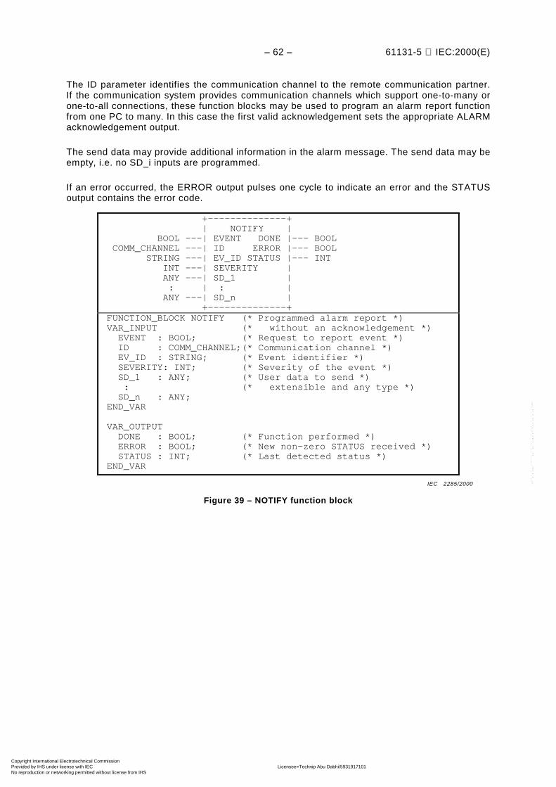
– 62 – 61131-5 IEC:2000(E)
The ID parameter identifies the communication channel to the remote communication partner.If the communication system provides communication channels which support one-to-many orone-to-all connections, these function blocks may be used to program an alarm report functionfrom one PC to many. In this case the first valid acknowledgement sets the appropriate ALARMacknowledgement output.
The send data may provide additional information in the alarm message. The send data may beempty, i.e. no SD_i inputs are programmed.
If an error occurred, the ERROR output pulses one cycle to indicate an error and the STATUSoutput contains the error code.
+--------------+ | NOTIFY | BOOL ---| EVENT DONE |--- BOOL COMM_CHANNEL ---| ID ERROR |--- BOOL STRING ---| EV_ID STATUS |--- INT INT ---| SEVERITY | ANY ---| SD_1 | : | : | ANY ---| SD_n | +--------------+ FUNCTION_BLOCK NOTIFY (* Programmed alarm report *) VAR_INPUT (* without an acknowledgement *) EVENT : BOOL; (* Request to report event *) ID : COMM_CHANNEL;(* Communication channel *) EV_ID : STRING; (* Event identifier *) SEVERITY: INT; (* Severity of the event *) SD_1 : ANY; (* User data to send *) : (* extensible and any type *) SD_n : ANY; END_VAR
VAR_OUTPUT DONE : BOOL; (* Function performed *) ERROR : BOOL; (* New non-zero STATUS received *) STATUS : INT; (* Last detected status *) END_VAR
Figure 39 – NOTIFY function block
IEC 2285/2000
Copyright International Electrotechnical Commission Provided by IHS under license with IEC Licensee=Technip Abu Dabhi/5931917101
Not for Resale, 02/12/2006 07:02:40 MSTNo reproduction or networking permitted without license from IHS
--``,`,`,,,``````,,``,,``,,,,`,-`-`,,`,,`,`,,`---

61131-5 IEC:2000(E) – 63 –
+-----------------+ | ALARM | BOOL ---| EN_R DONE |--- BOOL BOOL ---| EVENT ERROR |--- BOOL COMM_CHANNEL ---| ID STATUS |--- INT STRING ---| EV_ID ACK_UP |--- BOOL INT ---| SEVERITY ACK_DN |--- BOOL ANY ---| SD_1 | : | : | ANY ---| SD_n | +-----------------+ FUNCTION_BLOCK ALARM (* Programmed alarm report *) VAR_INPUT (* with an acknowledgement *) EN_R : BOOL; (* Enable alarming function *) EVENT : BOOL; (* Request to report event *) ID : COMM_CHANNEL;(* Communication channel *) EV_ID : STRING; (* Event identifier *) SEVERITY: INT; (* Severity of the event *) SD_1 : ANY; (* User data to send *) : (* extensible and any type *) SD_n : ANY; END_VAR
VAR_OUTPUT DONE : BOOL; (* Function performed *) ERROR : BOOL; (* New non-zero STATUS received *) STATUS : INT; (* Last detected status *) ACK_UP : BOOL; (* Acknowledged coming event *) ACK_DN : BOOL; (* Acknowledged going event *) END_VAR
Figure 40 – ALARM function block
IEC 2286/2000
Copyright International Electrotechnical Commission Provided by IHS under license with IEC Licensee=Technip Abu Dabhi/5931917101
Not for Resale, 02/12/2006 07:02:40 MSTNo reproduction or networking permitted without license from IHS
--``,`,`,,,``````,,``,,``,,,,`,-`-`,,`,,`,`,,`---

– 64 – 61131-5 IEC:2000(E)
Requester's ALARM block: +-------------------+ +-----------+ EVENT | | | | ----+ +-----------+ +---------- t0 t2 t4 t6
+---------------------+ +--- ACK_UP | | | ----------------+ +----------------+ t1 t5
+----------------+ ACK_DN | | ---------------------------------+ +-------- t3 t7 TIMING RELATIONSHIPS: t1 = t0 + tXC + tAC (Transmit time and acknowledge delay of coming event) t2 > t0 t3 = t2 + tXG + tAG (Transmit time and acknowledge delay of going event) t4 > t2 t5 = t4 + tRC (Delay from coming to resetting ACK_UP) t6 > t4 t7 = t6 + tRG (Delay from going to resetting ACK_DN) EVENT IDENTIFICATION: t0: Coming of the event t1: Acknowledgement of coming event t2: Going of the event t3: Acknowledgement of going event t4: Renewed coming of the event t5: Reset of the ACK_UP output t6: Renewed going of the event t7: Reset of the ACK_DN output
Figure 41 – Timing diagram of ALARM function block
IEC 2287/2000
Copyright International Electrotechnical Commission Provided by IHS under license with IEC Licensee=Technip Abu Dabhi/5931917101
Not for Resale, 02/12/2006 07:02:40 MSTNo reproduction or networking permitted without license from IHS
--``,`,`,,,``````,,``,,``,,,,`,-`-`,,`,,`,`,,`---

61131-5 IEC:2000(E) – 65 –
The state diagram shown in figure 42 describes the algorithm of the NOTIFY function block.Tables 45 and 46 describe the transitions of this state diagram and the actions to be performedwithin the states and the settings of the NOTIFY function block outputs.
1
INIT
4
6 6
ERROR
2 3
4
3
5
5
TRY_DOWN
IDLE
SENT_DOWN
SENT_UP
TRY_UP
IEC 2288/2000
Figure 42 – State diagram of NOTIFY function block
Table 45 – Transitions of the NOTIFY state diagram
Transition Condition
1 Initialization done
2 Raising edge of EVENT input
3 Falling edge of EVENT input
4 Communication system indicates "Sent to remote commu-nication partner"
5 Communication system indicates "Cannot send to remotecommunication partner"
6 After next invocation of this instance
Copyright International Electrotechnical Commission Provided by IHS under license with IEC Licensee=Technip Abu Dabhi/5931917101
Not for Resale, 02/12/2006 07:02:40 MSTNo reproduction or networking permitted without license from IHS
--``,`,`,,,``````,,``,,``,,,,`,-`-`,,`,,`,`,,`---

– 66 – 61131-5 IEC:2000(E)
Table 46 – Action table for NOTIFY state diagram
FB outputs
State Actions DONE c ERROR c STATUS
INIT a Initialize outputs 0 0 0
IDLE No actions 0 0 0
TRY_UP Request to report the coming alarm to theremote communication partner
0 0 ---
SENT_UP No actions 1 0 ---
TRY_DOWN Request to report the going alarm to theremote communication partner
0 0 ---
SENT_DOWN No actions 1 0 ---
ERROR Indicate error 0 1 b
--- indicates "unchanged" FB outputs.a INIT is the cold start state.b The error code is placed in the status output.c See figure 10.
Copyright International Electrotechnical Commission Provided by IHS under license with IEC Licensee=Technip Abu Dabhi/5931917101
Not for Resale, 02/12/2006 07:02:40 MSTNo reproduction or networking permitted without license from IHS
--``,`,`,,,``````,,``,,``,,,,`,-`-`,,`,,`,`,,`---
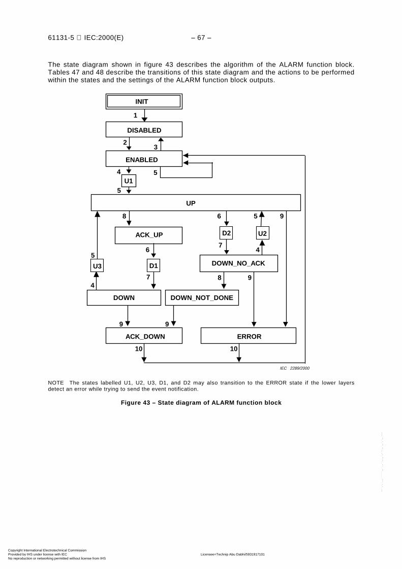
61131-5 IEC:2000(E) – 67 –
The state diagram shown in figure 43 describes the algorithm of the ALARM function block.Tables 47 and 48 describe the transitions of this state diagram and the actions to be performedwithin the states and the settings of the ALARM function block outputs.
4
8
8
5
2
1
9
10 10
6
3
94
UP
ACK_UP
DOWN_NO_ACK
DOWN
ACK_DOWN ERROR
ENABLED
DISABLED
9
INIT
U3
D2
6
D1
U2
5
7
7
5
5
4U1
9
DOWN_NOT_DONE
IEC 2289/2000
NOTE The states labelled U1, U2, U3, D1, and D2 may also transition to the ERROR state if the lower layersdetect an error while trying to send the event notification.
Figure 43 – State diagram of ALARM function block
Copyright International Electrotechnical Commission Provided by IHS under license with IEC Licensee=Technip Abu Dabhi/5931917101
Not for Resale, 02/12/2006 07:02:40 MSTNo reproduction or networking permitted without license from IHS
--``,`,`,,,``````,,``,,``,,,,`,-`-`,,`,,`,`,,`---
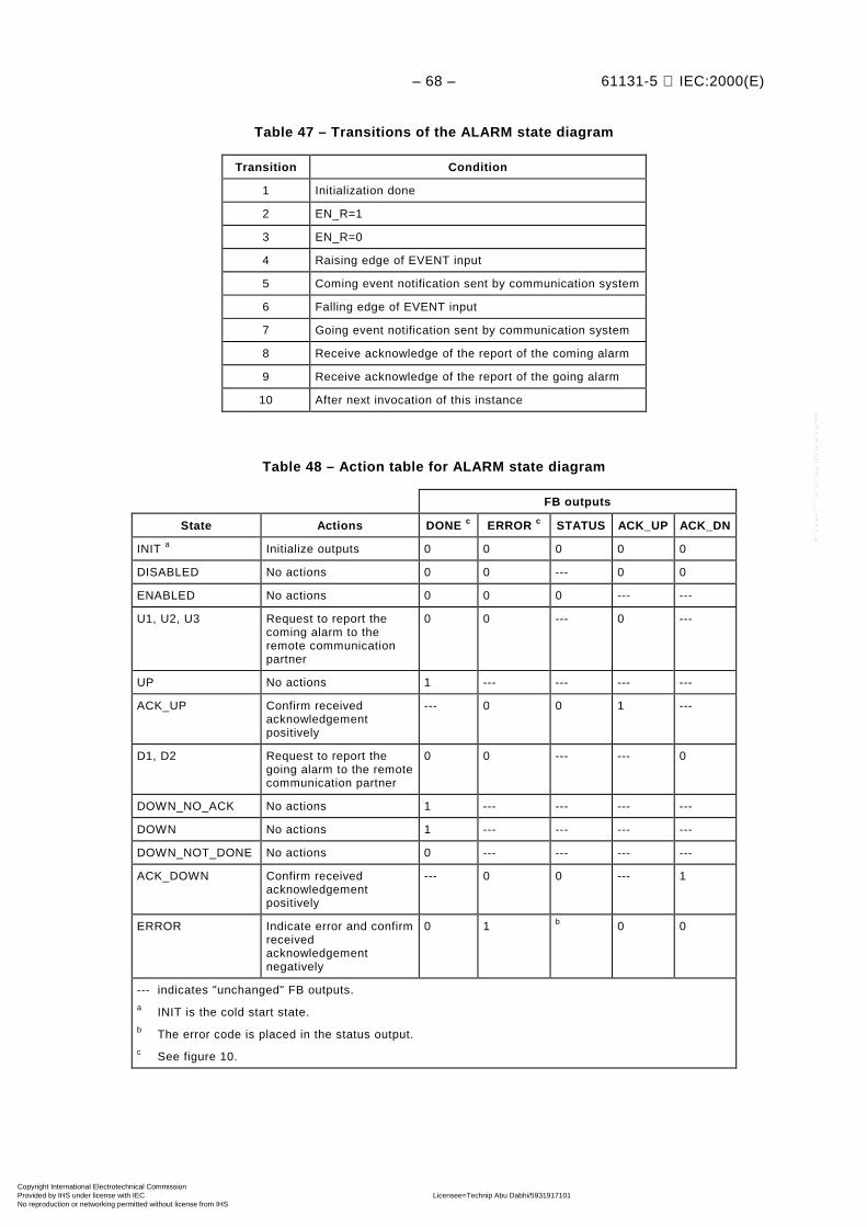
– 68 – 61131-5 IEC:2000(E)
Table 47 – Transitions of the ALARM state diagram
Transition Condition
1 Initialization done
2 EN_R=1
3 EN_R=0
4 Raising edge of EVENT input
5 Coming event notification sent by communication system
6 Falling edge of EVENT input
7 Going event notification sent by communication system
8 Receive acknowledge of the report of the coming alarm
9 Receive acknowledge of the report of the going alarm
10 After next invocation of this instance
Table 48 – Action table for ALARM state diagram
FB outputs
State Actions DONE c ERROR c STATUS ACK_UP ACK_DN
INIT a Initialize outputs 0 0 0 0 0
DISABLED No actions 0 0 --- 0 0
ENABLED No actions 0 0 0 --- ---
U1, U2, U3 Request to report thecoming alarm to theremote communicationpartner
0 0 --- 0 ---
UP No actions 1 --- --- --- ---
ACK_UP Confirm receivedacknowledgementpositively
--- 0 0 1 ---
D1, D2 Request to report thegoing alarm to the remotecommunication partner
0 0 --- --- 0
DOWN_NO_ACK No actions 1 --- --- --- ---
DOWN No actions 1 --- --- --- ---
DOWN_NOT_DONE No actions 0 --- --- --- ---
ACK_DOWN Confirm receivedacknowledgementpositively
--- 0 0 --- 1
ERROR Indicate error and confirmreceivedacknowledgementnegatively
0 1 b 0 0
--- indicates "unchanged" FB outputs.a INIT is the cold start state.b The error code is placed in the status output.c See figure 10.
Copyright International Electrotechnical Commission Provided by IHS under license with IEC Licensee=Technip Abu Dabhi/5931917101
Not for Resale, 02/12/2006 07:02:40 MSTNo reproduction or networking permitted without license from IHS
--``,`,`,,,``````,,``,,``,,,,`,-`-`,,`,,`,`,,`---

61131-5 IEC:2000(E) – 69 –
7.9 Connection management
The PC communication function connection management uses the CONNECT function block.
One instance of one CONNECT function block provides one instance of the PC functionconnection management. This communication function allows to establish a connectionbetween the calling communication partner and the remote communication partner.
A PC can request a remote communication partner to establish a connection between this PCand the remote communication partner. The remote communication partner is identified usingits name. (The name shall be specified by means of the implementer of the remote commu-nication partner.) A communication channel to the remote communication partner is defined.
The remote communication partner shall decide whether or not to establish the connection.
If the invocation of a CONNECT function block establishes a communication channel to aremote communication partner, the ID output shall provide the communication channeldescriptor which can be used as an input for the ID input to other communication functionblocks which communicates with this remote communication partner.
The remote communication partner itself may also use this connection for its communication asa client. The remote communication partner can get the necessary value of the ID parameterby calling a CONNECT function block referencing the communication partner which hasalready established the connection.
If an error occurred, the ERROR output pulses one cycle to indicate an error and the STATUSoutput contains the error code.
A communication channel may also be established by local means of the PC on one or bothsides of the communication channel. In this case the PC shall show the same behavior as if theCONNECT function block for this communication channel is invoked at the beginning of theapplication program cycle with the EN_C parameter fixed to 1. The implementer shall definehow the application program can get the appropriate value for the ID parameter to use thiscommunication channel.
+---------------+ | CONNECT | BOOL ---| EN_C VALID |--- BOOL (Note) ---| PARTNER ERROR |--- BOOL | STATUS |--- INT | ID |--- COMM_CHANNEL +---------------+ FUNCTION_BLOCK CONNECT (* Connection management *) VAR_INPUT EN_C : BOOL; (* Enable connection *) PARTNER: (Note); (* Name of the remote communication *) (* partner *) END_VAR
VAR_OUTPUT VALID : BOOL; (* Connection ID valid *) ERROR : BOOL; (* New non-zero STATUS received *) STATUS: INT; (* Last detected status *) ID : COMM_CHANNEL;(* Communication channel *) END_VAR
NOTE The data type of the input PARTNER is implementer specific. Additional information may beprovided with this parameter which may be used to establish the communication channel, forexample, a password or some communication subsystem specific parameters.
Figure 44 – CONNECT function block
IEC 2290/2000
Copyright International Electrotechnical Commission Provided by IHS under license with IEC Licensee=Technip Abu Dabhi/5931917101
Not for Resale, 02/12/2006 07:02:40 MSTNo reproduction or networking permitted without license from IHS
--``,`,`,,,``````,,``,,``,,,,`,-`-`,,`,,`,`,,`---

– 70 – 61131-5 IEC:2000(E)
Existence of the connection: +-----------------------------+ | | ---------+ +----------------- t1 t4
Requester's CONNECT block: +------------------------------+ EN_C | | ----+ +--------------------- t0 t3
+----------------------------+ VALID | | ---------------+ +------------- t2 t5 TIMING RELATIONSHIPS: t1 = t0 + tAD + tX (Time to establish the connection) t2 = t1 + tNC (Time to next invocation) t4 = t3 + tAD (Time to conclude the connection) t5 = t4 + tNC (Time to next invocation) EVENT IDENTIFICATION: t0: Request to establish a connection to the remote communication partner t1: Connection is established t2: Validity of the new connection is signalled to the application program t3: Request to conclude the connection t4: The connection is concluded t5: Conclusion of the connection is signalled
Figure 45 – Timing diagram of CONNECT function block
IEC 2291/2000
Copyright International Electrotechnical Commission Provided by IHS under license with IEC Licensee=Technip Abu Dabhi/5931917101
Not for Resale, 02/12/2006 07:02:40 MSTNo reproduction or networking permitted without license from IHS
--``,`,`,,,``````,,``,,``,,,,`,-`-`,,`,,`,`,,`---

61131-5 IEC:2000(E) – 71 –
The state diagram shown in figure 46 describes the algorithm of the CONNECT function block.Tables 49 and 50 describe the transitions of this state diagram and the actions to be performedwithin the states and the settings of the CONNECT function block outputs.
2
8
13
13
5
14
13 7614
10 3
14
8
8 10 2 11 12
4
13
3
11
1214
9
1
CONCLUDING
ERROR ERROR
ABORT_2
CHECKING_2
CONNECTING
RETRYABORT_1
DENY
CLOSINGRETRY
CONCL_PASSIV
ACCEPT
CHECKING_1
CONNECTED
INIT
IDLE
13
Request connectionAccept connection
IEC 2292/2000
Figure 46 – State diagram of CONNECT function block
Copyright International Electrotechnical Commission Provided by IHS under license with IEC Licensee=Technip Abu Dabhi/5931917101
Not for Resale, 02/12/2006 07:02:40 MSTNo reproduction or networking permitted without license from IHS
--``,`,`,,,``````,,``,,``,,,,`,-`-`,,`,,`,`,,`---

– 72 – 61131-5 IEC:2000(E)
Table 49 – Transitions of the CONNECT state diagram
Transition Condition
1 Initialization done
2 EN_C=1
3 EN_C=0
4 Receive a positive confirmation to the request to establisha new connection from the remote communication partner
5 Receive a negative confirmation to the request to establisha new connection from the remote communication partner
6 Receive a positive confirmation to the request to concludethe connection from the remote communication partner
7 Receive a negative confirmation to the request to concludethe connection from the remote communication partner
8 Loss of connection
9 Receive a request to establish a new connection tothe remote communication partner
10 Receive a request to conclude the connection tothe remote communication partner
11 Accept to establish a connection
12 Deny to establish a connection
13 Next invocation
14 Immediately
Copyright International Electrotechnical Commission Provided by IHS under license with IEC Licensee=Technip Abu Dabhi/5931917101
Not for Resale, 02/12/2006 07:02:40 MSTNo reproduction or networking permitted without license from IHS
--``,`,`,,,``````,,``,,``,,,,`,-`-`,,`,,`,`,,`---

61131-5 IEC:2000(E) – 73 –
Table 50 – Action table for CONNECT state diagram
FB outputs
State Actions VALID ERROR d STATUS ID c
INIT a Initialize outputs 0 0 0 NG
IDLE No actions 0 --- --- NG
CHECKING_1 Check if the connectioncan be established
0 --- --- NG
DENY Send negative response tothe request of theconnection
0 --- --- NG
ACCEPT Accept to establish aconnection and a send apositive response
0 0 --- NG
CONCL_PASSIV Send a positive responseto conclude the connection
0 --- --- NG
CONNECTING Request a connection tothe remote communicationpartner
0 0 –1 NG
ABORT_1 Request to abortcommunication
0 --- --- NG
CHECKING_2 Check if the connectioncan be established
0 0 --- NG
ABORT_2 Request to abortcommunication
0 --- --- NG
CONNECTED No action 1 0 0 OK
RETRY No action 0 1 1 NG
CLOSING Request to concludethe connection
0 0 –1 NG
CONCLUDING Send positive response toconclude the connection
0 0 --- NG
ERROR Indicate error 0 1 b NG
--- indicates "unchanged" FB output.a INIT is the cold start state.b The error code is placed in the status output.c NG indicates "invalid connection ID" OK indicates "valid connection ID".d See figure 10.
7.10 Example for the use of communication function blocks
7.10.1 Establishing a communication channel
Two PCs want to establish a communication channel. Both of the PCs want to use the channelfor client and server function, i.e. both need to get an appropriate value for their ID parameterof the Communication function blocks. In this example, it is assumed that the data typeCOMM_CHANNEL stands for a handle or index of the communication channel. The example isgiven using the Structured Text programming language as defined in IEC 61131-3.
Copyright International Electrotechnical Commission Provided by IHS under license with IEC Licensee=Technip Abu Dabhi/5931917101
Not for Resale, 02/12/2006 07:02:40 MSTNo reproduction or networking permitted without license from IHS
--``,`,`,,,``````,,``,,``,,,,`,-`-`,,`,,`,`,,`---

– 74 – 61131-5 IEC:2000(E)
Extract of the application program of PC1:
(* Declaration of the data and the CONNECT instance, e.g. at the beginning of an application program *)VARTO_PC2: COMM_CHANNEL; (* Variable which is set by CONNECT *):CO1: CONNECT; (* Declaration of the CONNECT instance *)END_VAR;
(* somewhere inside the body of the program *)
CO1(EN_C:=1, PARTNER:='PC2'); (* Invokes the CONNECT instance CO1 andestablishes a communication channel to PC2 *)
IF CO1.ERROR THEN (* It is recommended to define some error handling *):IF CO1.VALID THEN (* Store reference of the communication channel *)TO_PC2:= CO1.ID;
Extract of the application program of PC2:
(* Declaration of the data and the CONNECT instance, e.g. at the beginningof an application program *)
VARTO_PC1: COMM_CHANNEL; (* Variable which is set by CONNECT *):CO2: CONNECT; (* Declaration of the CONNECT instance *)END_VAR;
(* somewhere inside the body of the program *)
CO2(EN_C:=1, PARTNER:='PC1'); (* Invokes the CONNECT instance CO2 andestablishes a communication channel to PC1 *)
IF CO2.ERROR THEN (* It is recommended to define some error handling *):IF CO2.VALID THEN (* Store reference of the communication channel *)TO_PC1:= CO2.ID;
These parts of the application program of PC1 and PC2 may be nearly identical. Thecommunication channel is established by the PC which invokes its CONNECT instance earlier.The later invoking PC gets the communication channel already established.
7.10.2 Transferring data
Two PCs want to communicate using an already established communication channel. Somedata shall be transferred from PC1 to PC2 using the USEND and URCV function blocks. Thefollowing parts of the applications programs show how this can be achieved. How theapplication programs provide and process the data to be transferred is not shown in thisexample. The example is given using the Structured Text programming language as defined inIEC 61131-3.
Extract of the application program of PC1 which uses an instance of the USEND function blockto send the data:
(* Declaration of the data and the USEND instance, e.g. in the definitionof a function block *)
VARSENDREQ: BOOL; (* Flag to request the send *)TO_PC2: COMM_CHANNEL; (* Variable which allows to use the communication
channel to PC2 *)SDAT1: ARRAY[0..20] OF BYTE; (* Declaration of the data to send *)SDAT2: REAL;US1: USEND; (* Declaration of the USEND instance *)END_VAR;
(* somewhere inside the body of the function block *)
US1(REQ:=SENDREQ, ID:=TO_PC2, R_ID=’PACK1’, SD_1:=SDAT1, SD_2:=SDAT2);(* Invokes the USEND instance US1 and will send the data on raising
edge of SENDREQ Boolean *)IF US1.ERROR THEN (* It is recommended to define some error handling *):
Copyright International Electrotechnical Commission Provided by IHS under license with IEC Licensee=Technip Abu Dabhi/5931917101
Not for Resale, 02/12/2006 07:02:40 MSTNo reproduction or networking permitted without license from IHS
--``,`,`,,,``````,,``,,``,,,,`,-`-`,,`,,`,`,,`---
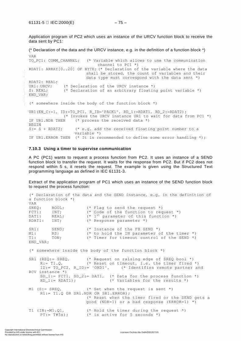
61131-5 IEC:2000(E) – 75 –
Application program of PC2 which uses an instance of the URCV function block to receive thedata sent by PC1:
(* Declaration of the data and the URCV instance, e.g. in the definition of a function block *)
VARTO_PC1: COMM_CHANNEL; (* Variable which allows to use the communication
channel to PC1 *)RDAT1: ARRAY[0..20] OF BYTE; (* Declaration of the variable where the data
shall be stored, the count of variables and theirdata type must correspond with the data sent *)
RDAT2: REAL;UR1: URCV; (* Declaration of the URCV instance *)S: REAL; (* Declaration of an arbitrary floating point variable *)END_VAR;
(* somewhere inside the body of the function block *)
UR1(EN_C:=1, ID:=TO_PC1, R_ID=’PACK1’, RD_1:=RDAT1, RD_2:=RDAT2);(* Invokes the URCV instance UR1 to wait for data from PC1 *)
IF UR1.NDR THEN (* process the received data *)BEGINS:= S + RDAT2; (* e.g. add the received floating point number to a
variable *)IF UR1.ERROR THEN (* It is recommended to define some error handling *);
7.10.3 Using a timer to supervise communication
A PC (PC1) wants to request a process function from PC2. It uses an instance of a SENDfunction block to transfer the request. It waits for the response from PC2. But if PC2 does notrespond within 5 s, it resets the request. The example is given using the Structured Textprogramming language as defined in IEC 61131-3.
Extract of the application program of PC1 which uses an instance of the SEND function blockto request the process function:
(* Declaration of the data and the SEND instance, e.g. in the definition ofa function block *)VARSREQ: BOOL; (* Flag to send the request *)FCT1: INT; (* Code of the function to request *)DAT1: REAL; (* 1st parameter of this function *)RDAT1: INT; (* Response parameter *)
SR1: SEND; (* Instance of the FB SEND *)M1: RS; (* to hold the IN parameter of the timer *)T1: TON; (* Timer for timeout control of the SEND *)END_VAR;
(* somewhere inside the body of the function block *)
SR1 (REQ:= SREQ, (* Request on raising edge of SREQ bool *)R:= T1.Q, (* Reset on timeout, i.e. the timer fired *)ID:= TO_PC2, R_ID:= 'ORD1', (* Identifies remote partner and
RCV instance *)SD_1:= FCT1, SD_2:= DAT1, (* Data for the process function *)RD_1:= RDAT1); (* Variables for the results *)
M1 (S:= SREQ, (* Set when the request is sent *)R1:= T1.Q OR SR1.NDR OR SR1.ERROR);
(* Reset when the timer fired or the SEND gets agood (NDR=1) or a bad response (ERROR=1) *)
T1 (IN:=M1.Q1, (* Hold the timer during the request *)PT:= T#5s); (* is active for 5 seconds *)
Copyright International Electrotechnical Commission Provided by IHS under license with IEC Licensee=Technip Abu Dabhi/5931917101
Not for Resale, 02/12/2006 07:02:40 MSTNo reproduction or networking permitted without license from IHS
--``,`,`,,,``````,,``,,``,,,,`,-`-`,,`,,`,`,,`---

– 76 – 61131-5 IEC:2000(E)
The same program part using the function block diagram as defined in IEC 61131-3 is shown infigure 47:
TON
IN QPT ET
RS
S Q1R1
>=1SEND
REQ NDRR ERRORID STATUSR_ID RD_1SD_1SD_2
SREQT1.Q
TO_PC2'ORD1'
FCT1DAT1
RDAT1
SR1 T1M1
T1.Q
T#5sSREQ
IEC 2293/2000
Figure 47 – Example in function block diagram language
8 Compliance and implementer specific features and parameters
8.1 Compliance
A PC system, as defined in IEC 61131-1, which claims to comply, wholly or partially, with therequirements of this part of IEC 61131 shall do so only as described below.
A compliance statement shall be included in the documentation accompanying the system, orshall be produced by the system itself. The form of the compliance statement shall be:
"This system complies with the requirements of this part for the following features:" followed bya set of compliance tables in the following format:
Table title
Table number Feature number Feature description
Table and feature numbers and descriptions are to be taken from the tables given in therelevant subclauses of this part of IEC 61131. The table titles and the relevant tables are to betaken from the following table 51.
Table 51 – Table titles and relevant tables for compliance
Table title For features in table
PC status Tables 1 to 9
Application specific functions Tables 10 to 20, except 15
PC communication function blocks Table 21
A PC system complying with the requirements of this part of IEC 61131 shall
a) not require the inclusion of substitute or additional features in order to accomplish any ofthe features specified in this part;
b) be accompanied by a document that specifies the values of all implementer specificfeatures or parameters as listed in the following table and in the table ‘Implementationspecific features and parameters’ of the appropriate annex;
c) be accompanied by a document that separately describes any communication relevantfeature that is prohibited or not specified in this part. Such features shall be described asbeing "extensions to the PC communication as defined in IEC 61131-5";
Copyright International Electrotechnical Commission Provided by IHS under license with IEC Licensee=Technip Abu Dabhi/5931917101
Not for Resale, 02/12/2006 07:02:40 MSTNo reproduction or networking permitted without license from IHS
--``,`,`,,,``````,,``,,``,,,,`,-`-`,,`,,`,`,,`---

61131-5 IEC:2000(E) – 77 –
d) not use any of the function or function block names defined in clause 7 for implementerdefined features whose functionality differs from that described there.
8.2 Implementation specific features and parameters
Implementation specific features and parameters defined in this part of IEC 61131 and themost relevant subclause for each are listed in the following table 52.
Table 52 – Implementation specific features and parameters
Subclause Implementation specific features and parameters
6.1 The definition of major and minor faults of the subsystems of the PC
6.1.8 The number of the subsystems of the PC providing status information
6.1.8 The types of the subsystems of the PC providing status information
6.1.8 The maximum size of the string containing names of the PC and of its subsystems
6.1.8 The semantic of the values in the sub-element STATE for the implementer specific subsystems
6.1.8 The size of the sub-element SPECIFIC of the status information
6.1.8 The semantic of the sub-element SPECIFIC of the status information
6.2.2 Restrictions of the access of variables with direct representation
6.2.2 The algorithm to access a variable with direct representation
6.2.2 The conditions (size, location, etc.) under which each data type supported by the PC can beuninterruptedly accessed
6.2.6 The supported values of I/O state
6.2.6 The definition of the outputs if the implementer specified value is requested
6.2.6 The definition of the mechanisms to specify the outputs if the user specified value is requested
6.2.7 Other language elements, for example, function types or function block types which are loadable andthe conditions and restrictions for downloading and uploading these
6.2.7 What other clients can do with a PC when one client is downloading it
7.2 The COMM_CHANNEL type used at the ID input of the communication function blocks identifying theremote communication partner
7.2 Data type of the VAR_ADDR output of the REMOTE_VAR function and the restrictions using theoutput of the REMOTE_VAR function
7.2 Name scopes the implemeter supports for use at SCOPE parameter of the REMOTE_VAR function
7.2 Mapping of the implementer specific name scopes onto the communication system
7.2 The number of SD_i, RD_i, and VAR_i parameters which are supported with one invocation of acommunication function block
7.2 The meaning of codes less than –1 or greater than 20 of the STATUS output of the communicationfunction blocks
7.2 Additional means (if there are some) to control the time by which the communication channel isestablished, if not explicitly controlled using the CONNECT function block
7.3 The used length and the semantics of the additional status information of the LOCAL output of theFB STATUS and FB USTATUS
7.9 How the user can get the information of the communication channel for the use at the ID input of thecommunication function blocks
Copyright International Electrotechnical Commission Provided by IHS under license with IEC Licensee=Technip Abu Dabhi/5931917101
Not for Resale, 02/12/2006 07:02:40 MSTNo reproduction or networking permitted without license from IHS
--``,`,`,,,``````,,``,,``,,,,`,-`-`,,`,,`,`,,`---

– 78 – 61131-5 IEC:2000(E)
Annex A (normative)
Mapping to ISO/IEC 9506-5
A.1 General
This annex specifies the mapping of the PC communication functions to the MMS objects andservices defined in ISO/IEC 9506-1 and extensions defined in ISO/IEC 9506-5. This mappingshall be used when a PC is communicating in the abstract syntax defined in ISO/IEC 9506-5.
Normative references
ISO 7498-1:1994, Information technology – Open Systems Interconnection – Basic ReferenceModel: The Basic Model
ISO/IEC 9506-1:1990, Industrial automation systems – Manufacturing Message Specification –Part 1: Service definitionAmendment 1:1993, Data exchange
ISO/IEC 9506-2:1990, Industrial automation systems – Manufacturing Message Specification –Part 2: Protocol specificationAmendment 1:1993, Data exchange
ISO/IEC 9506-5:1999, Industrial automation systems – Manufacturing Message Specification –Part 5: Companion standard for programmable controllers
Definitions from other publications
ISO 7498-1
application entity (AE)
ISO/IEC 9506-1
domain
program invocation (PI)
server
Virtual Manufacturing Device (VMD) (clause 7)
Abbreviations
Cnf This is the confirmation primitive of a communication service
Ind This is the indication primitive of a communication service
Req This is the request primitive of a communication service
Rsp This is the response primitive of a communication service
VMD Virtual Manufacturing Device
Copyright International Electrotechnical Commission Provided by IHS under license with IEC Licensee=Technip Abu Dabhi/5931917101
Not for Resale, 02/12/2006 07:02:40 MSTNo reproduction or networking permitted without license from IHS
--``,`,`,,,``````,,``,,``,,,,`,-`-`,,`,,`,`,,`---
61131-5 IEC:2000(E) – 79 –
A.2 Application specific functions
A.2.1 Device verification
A PC can provide some very general status to a requesting device via the MMS Status service.The contents of this status is defined by MMS. The implementer can provide Local Detail (bitstring with a maximum length of 128 bits) that contains additional information. The PC caninitiate an unsolicited status report of this same information using the MMS UnsolicitedStatusservice.
NOTE The 16 lowest numbered bits of Local Detail may provide, for example the same information as in theP_PCSTATE variable (see table 2 and 6.1.8).
A PC can provide detailed status information about the PC and its subsystems via MMS NamedVariables or MMS Unnamed Variables or both (see 6.1.8). These variables can be read usingthe MMS Read service. For the specification of these variables (see 6.1.8).
A.2.2 Data acquisition
Data contained in a PC is presented as PC variables. Selected PC variables are mapped ontoMMS Named Variables, using the access path language construct (see A.3.2). Additionally,variables with direct representation are mapped onto MMS Unnamed Variables, withimplementer specified restrictions. The content of these variables can be provided to a clientusing the MMS Read and InformationReport services.
A.2.3 Parametric control
Parametric control is when the operation of the PC is directed by writing values to PCvariables. This change in operation is determined by either the application program or otherlocal mechanisms. The MMS Write service is used to write a new value to a PC variable.
A.2.4 Interlocked control
Interlocked control is when the client requests the server to execute an application operationand to inform the client of the result of the operation. The SEND and RCV function blocks areused to provide this function. See A.4 for the mapping of these function blocks onto MMSobjects and services.
A.2.5 Synchronization between user applications
User applications may need a synchronization service. This PC function is provided by thecommunication function interlocked control (see 6.2.3 and A.2.4).
A.2.6 Alarm reporting
The PC can have the ability to signal alarm messages to a client when a predeterminedcondition occurs. The ALARM and NOTIFY function blocks are used to provide this function.See A.4 for the mapping of these function blocks onto MMS objects and services.
A.2.7 Application program execution and I/O control
Program execution and I/O control uses the language elements configuration and resource ofIEC 61131-3 (see 6.2).
The configuration and resource are mapped onto MMS Program Invocation objects.
The state of the I/O (inputs and outputs) associated with a resource is specified using thevarious MMS services which operate on Program Invocations using the I/O State parameter, asdefined in ISO/IEC 9506-5.
Copyright International Electrotechnical Commission Provided by IHS under license with IEC Licensee=Technip Abu Dabhi/5931917101
Not for Resale, 02/12/2006 07:02:40 MSTNo reproduction or networking permitted without license from IHS
--``,`,`,,,``````,,``,,``,,,,`,-`-`,,`,,`,`,,`---

– 80 – 61131-5 IEC:2000(E)
A.2.8 Application program transfer
Application program transfer allows the client to upload the complete contents of theprogrammable memory or portions thereof for archiving or verification or to download it forrestoring the PC to a known state. The portions of the programmable memory which can beuploaded or downloaded were specified in 6.2.7. These loadable units are mapped onto theMMS Domain object. They are transferred using the MMS Domain services.
A.2.9 Connection management
The MMS Environment and General Management services are used to manage theconnections.
A.3 PC object mapping
ISO/IEC 9506 supports an object-oriented view to the communication. A PC communicating inthe abstract syntax of ISO/IEC 9506-5 is mapped onto a virtual device. This virtual devicecontains all objects visible to a remote communication partner and services all requests comingfrom a remote communication partner.
A.3.1 VMD
One PC, a part of a PC, or a set of several PCs may be mapped onto one VMD. Thecommunication to this VMD shall conform to ISO/IEC 9506-5.
The implementer shall specify this mapping. This part of IEC 61131 does not define anyrestrictions to the attributes of the VMD.
A.3.2 Named Variables
Each access path is mapped onto one MMS Named Variable. The attributes of the MMSNamed Variable are as follows:
Object: Named Variable
Attribute: Variable Name – This shall be the access name from the access path declaration.If the access path definition references variables with direct representation, program inputsor outputs, or global variables of configurations or resources (see 2.7.1 of IEC 61131-3),the name shall have VMD-specific scope. If the access path definition is at program level(see 2.5.3 of IEC 61131-3), the name shall be domain specific of the domain which isassociated with the program which contains the referenced variable (see A.2.9).
Attribute: Reference to Access Control List – If the access path contains the READ_ONLYlanguage element this object shall reference the Access Control List object M_ReadOnlyotherwise M_NonDeletable.
Attribute: Type Description – This shall be the data type as specified in the access pathdeclaration mapped to MMS according to table A.1.
Copyright International Electrotechnical Commission Provided by IHS under license with IEC Licensee=Technip Abu Dabhi/5931917101
Not for Resale, 02/12/2006 07:02:40 MSTNo reproduction or networking permitted without license from IHS
--``,`,`,,,``````,,``,,``,,,,`,-`-`,,`,,`,`,,`---

61131-5 IEC:2000(E) – 81 –
Table A.1 – Type description mapping
No. Access path data type keyword MMS type description class and size Notes
1 BOOL boolean
2 SINT integer 8 4
3 INT integer 16 4
4 DINT integer 32 4
5 LINT integer 64 4
6 USINT unsigned 8 4
7 UINT unsigned 16 4
8 UDINT unsigned 32 4
9 ULINT unsigned 64 4
10 REAL floating-point 32,8 4
11 LREAL floating-point 64,11 4
12 TIME unsigned 32 4
13 DATE binary-time true 1
14 TIME_OF_DAY, TOD binary-time false 1
15 DATE_AND_TIME, DT binary-time true 1
16 STRING[N] octet-string N 2
17 BYTE bit-string 8 4
18 WORD bit-string 16 4
19 DWORD bit-string 32 4
20 LWORD bit-string 64 4
21 enumerated_specification integer 3
22 subrange_specification basic data type of the subrange
23 ARRAY array
24 STRUC structure
NOTE 1 The values true and false indicate that data is included or not included, respectively.
NOTE 2 The implementer shall specify the maximum length permitted, the given size N is the maximum sizeof the string.
NOTE 3 The size of the integer shall be selected to hold all possible enumerated values.
NOTE 4 The given size is fixed.
Variables may be addressed using the REMOTE_VAR function. The mapping of theparameters SCOPE and SC_ID are as follows:
Table A.2 – Mapping of the SCOPE and SC_ID parameter
Value of SCOPE parameter MMS name scope Usage of the SC_ID parameter
0 VMD Not used
1 VMD Not used
2 Domain Domain name
3 Domain Domain name
10 VMD Not used
11 Domain Domain name
12 ApplicationAssociation
AA name
Copyright International Electrotechnical Commission Provided by IHS under license with IEC Licensee=Technip Abu Dabhi/5931917101
Not for Resale, 02/12/2006 07:02:40 MSTNo reproduction or networking permitted without license from IHS
--``,`,`,,,``````,,``,,``,,,,`,-`-`,,`,,`,`,,`---

– 82 – 61131-5 IEC:2000(E)
A.3.3 Unnamed Variables
Object: Unnamed Variable
Attribute: Address – The Kind of Address parameter has the value ‘Symbolic Address’. Thevalue of the Symbolic Address parameter shall be the direct representation of the PCvariable.
Attribute: Type Description – This shall be the data type derived from the size prefix of thedirect representation mapped according to the following table.
Table A.3 – Size prefix of direct representation
Number Size prefix of direct representation MMS type description class and size
1 (none) boolean
2 X boolean
3 B bit-string 8
4 W bit-string 16
5 D bit-string 32
6 L bit-string 64
NOTE The programming languages of IEC 61131-3 define the means of representing variablessymbolically, or alternatively in a manner which directly represents the association of the dataelement with physical or logical locations in the programmable controller’s input, output, or memorystructure. The Unnamed Variable object is used to access the variables with direct representation.
A.3.4 Program Invocations
Object: Program Invocation
Attribute: Program Invocation Name – This shall be the name of the associatedconfiguration or resource.
Attribute: Reusable – This shall have the value TRUE.
Attribute: Additional Detail – This consists of the following attributes defined in ISO/IEC9506-5:
1. Independent – This attribute has the value TRUE if the associated PC languageelement is a configuration, otherwise it has the value FALSE.
2. Constraint: Independent = FALSE
Program Invocation Reference – This attribute has the value of the identifier of theconfiguration.
3. I/O state
The implementer may define additional means to create additional Program Invocation objects.
A.3.5 Domains
Object: Domain
Attribute: Domain Name – This shall be the name of the associated loadable unit.
Attribute: List of Subordinate Objects – If the Named Variable P_DDATE is supported bythe implementation, it shall appear in this attribute.
The implementer may define additional means to create additional Domain objects.
Copyright International Electrotechnical Commission Provided by IHS under license with IEC Licensee=Technip Abu Dabhi/5931917101
Not for Resale, 02/12/2006 07:02:40 MSTNo reproduction or networking permitted without license from IHS
--``,`,`,,,``````,,``,,``,,,,`,-`-`,,`,,`,`,,`---

61131-5 IEC:2000(E) – 83 –
A.4 Communication function block mapping to MMS objects and services
The communication function blocks are described using state diagrams with transitions andactions. In this part of the annex, all transitions and actions which refer to the PC commu-nication system are mapped onto ISO/IEC 9506-5.
A.4.1 Using communication channels
Only one-to-one communication channels are provided with ISO/IEC 9506-5.
All requests and all responses mentioned in the following clauses are transmitted using theapplication association which is referenced by the ID parameter of the communication functionblocks. Indications or confirmations have effect to a certain communication function blockinstance only if they were received using the application association referenced by its IDparameter.
A.4.2 Rules for data type compatibility
The following rules shall apply, when a data protocol unit is received and the action requests toverify if the data type of the received variable object matches with the data type of anapplication program variable programmed at an RD_i output parameter of the receivingfunction block.
a) If the application program variable programmed at the RD_i parameter is of a signed orunsigned integer data type, any received variable of signed or unsigned integer type, thevalue of which can be stored without loss of information shall pass the type check. Theapplication program variable shall get the value of the received variable object.
b) If the application program variable programmed at the RD_i parameter is of BYTE, WORD,DWORD, or LWORD data type, any received variable of bit-string type with a length ofwhich is not bigger than the bit length of the application program variable shall pass thetype check. The application program variable shall get the value of the received variableobject, storing bit 0 of the received bit-string into bit 0 of the application program variableand so on. The application program variable is filled up with 0 if its length is bigger.
c) If the application program variable programmed at the RD_i parameter is of STRING datatype, any received variable with a byte length of which is not bigger than the byte length ofthe application program variable shall pass the type check. The application programSTRING variable shall get the value of the received variable object, storing byte 1 of thereceived variable into byte 1 of the application program STRING variable and so on. Thelength of the string shall be set to the count of the received and stored bytes.
d) If the received variable object has the data type octet string the type check shall be passed,if the application program variable has a byte length which is not smaller than the length ofthe received octet string. The application program variable shall get the value of thereceived octet string, storing byte 1 of the received variable into byte 1 of the applicationprogram variable and so on. The application program variable is filled up with 0 if its lengthis bigger.
e) If the application program variable programmed at the RD_i parameter is of a data type notmentioned in rule a) to c) and rule d) does not apply, the type check shall be passed if thedata type of the received MMS variable object corresponds with the data type of theapplication program variable using tables A.1 and A.3. The application program variableshall get the value of the received variable object.
A.4.3 Device verification
The STATUS function block uses the Status service as a client.
Copyright International Electrotechnical Commission Provided by IHS under license with IEC Licensee=Technip Abu Dabhi/5931917101
Not for Resale, 02/12/2006 07:02:40 MSTNo reproduction or networking permitted without license from IHS
--``,`,`,,,``````,,``,,``,,,,`,-`-`,,`,,`,`,,`---

– 84 – 61131-5 IEC:2000(E)
Table A.4 – Transition mapping of the STATUS state diagram
Transition Condition
3 Positive response from remote communication partner:
Status.Cnf(+)
4 Negative response from remote communication partnerreceived or communication problems detected:
Status.Cnf(–) orlower layers indicate error
Table A.5 – Action mapping for STATUS state diagram
State Actions
WAITING Request status information from remote device:
Status.Req:Extended Derivation: FALSE
HAVE_DATA Deposit status information in instance:
Status.Cnf(+):VMD Logical Status to LOG outputVMD Physical Status to PHYS outputLocal Detail to LOCAL output
The USTATUS function block uses the Unsolicited Status service as a receiver.
Table A.6 – Transition mapping of USTATUS state diagram
Transition Condition
4 Status information received from remote communicationpartner:
UnsolicitedStatus.Ind
5 Communication problems detected:
Lower layers indicate error
Table A.7 – Action mapping of USTATUS state diagram
State Actions
HAVE_DATA Deposit status information in instance:
UnsolicitedStatus.Ind:VMD Logical Status to LOG outputVMD Physical Status to PHYS outputLocal Detail to LOCAL output
A.4.4 Polled data acquisition
The READ function block uses the Read service as a client.
The strings and the outputs of the REMOTE_VAR function given in the VAR_i input asidentifiers of the variables to be read are mapped onto the Variable Access Specificationparameter of the Read request. Each identifier of a VAR_i input forms one element of the Listof Variable selection.
Copyright International Electrotechnical Commission Provided by IHS under license with IEC Licensee=Technip Abu Dabhi/5931917101
Not for Resale, 02/12/2006 07:02:40 MSTNo reproduction or networking permitted without license from IHS
--``,`,`,,,``````,,``,,``,,,,`,-`-`,,`,,`,`,,`---

61131-5 IEC:2000(E) – 85 –
If the string of a VAR_i input starts with a "%" character, an Unnamed Variable object with aSymbolic Address shall be read. The string of the VAR_i input is used in the symbolicAddressparameter. Otherwise a VMD-specific variable shall be read. The Name Scope parameter ofthe Object Name parameter shall be set to VMD-specific. The string is used as the identifier.
If a REMOTE_VAR function output is used to identify the remote variable to be read, the NameScope parameter of the Object Name parameter shall be set as given in the SCOPE input ofthe REMOTE_VAR function and mapped using table A.2. If the scope is VMD-specific or AA-specific, the value of the NAME input is used as the identifier. If the scope is domain specificthe value of the SC_ID input shall be used as identifier of the Domain, and the value of theNAME input as item identifier.
If a derived variable is to be read, the Alternate Access option of the Variable AccessSpecification is used to describe which sub-element of a structure or element of an array is tobe read. The List of Alternate Access Selections shall contain exactly one element. If the SUBinput of the REMOTE_VAR function is an integer (signed or unsigned), it shall be used as theIndex of the array element to be read. If the SUB input is a not empty string, it shall be used asthe component name of the sub-element to be read.
Table A.8 – Transition mapping of the READ state diagram
Transition Condition
3 Positive response from remote communication partner:
Read.Cnf(+)
4 Negative response from remote communication partneror other communication problems detected:
Read.Cnf(–) orlower layers indicate error
Table A.9 – Action mapping for READ state diagram
State Actions
WAITING Request variables from remote device:
Read.ReqSpecification With Result= FALSEVariable Access Specification
CHECKING Verify data type match:
Check all elements of the List of Access Results against the RD_i outputdeclaration:
If Success is false, the check failsIf the Kind of Data parameter does not match (see A.4.2) with the datatype of the appropriate RD_i output, the check fails.If the check of one data element fails, the complete check fails.
HAVE_DATA Deposit data:
Deposit all data elements of the List of Access Results in the RD_i outputs
A.4.5 Programmed data acquisition
The USEND function block uses the Information Report service as a requester.
One instance of an USEND function block defines a Named Variable object with AA-specificscope. The attributes of this object are as follows:
Copyright International Electrotechnical Commission Provided by IHS under license with IEC Licensee=Technip Abu Dabhi/5931917101
Not for Resale, 02/12/2006 07:02:40 MSTNo reproduction or networking permitted without license from IHS
--``,`,`,,,``````,,``,,``,,,,`,-`-`,,`,,`,`,,`---

– 86 – 61131-5 IEC:2000(E)
Object: Named Variable
Attribute: Variable Name – The string given at the R_ID input parameter is the name of thevariable with AA-specific scope.
Attribute: Reference to Access Control List – This object shall reference the Access ControlList object M_ReadOnly.
Attribute: Type Description – If only one send data parameter is given, the type of theNamed Variable object is exactly the type of the send data using tables A.1 and A.3. If morethan one send data parameter is programmed, the type of the Named Variable object is astructure containing the send data as components in the same order and with the sametype as given as send data parameters.
Table A.10 – Transition mapping of the USEND state diagram
Transition Condition
3 Communication system indicates "Sent to Remote Communication partner"
Lower Layers indicate no errors
4 Communication system indicates "Cannot Send to Remote Communication partner" orother communication problems detected:
Lower layers indicate error
Table A.11 – Action mapping for USEND state diagram
State Actions
TRYING Send data given at the SD_i inputs to remote communication partner:
InformationReport.ReqVariable Access Specification
Kind Of Variable= NAMEDName
Name Scope= AA-SPECIFICItem Identifier= Content of R_ID input
List of Access Results
The URCV function block uses the Information Report service as a receiver.
The string given in the R_ID input is used as the name of the Named Variable object with AA-specific scope which shall be received by the instance of the URCV function block. If only onedata output RD_1 is given the type of this parameter shall be checked with the type of thereceived variable, see A.4.2. If more than one data output RD_1 ... RD_n is given, the type ofthe received variable object shall be a structure containing the data for the different parametersas components in the same order and with the same type as given in the function blockinstance.
Table A.12 – Transition mapping of URCV state diagram
Transition Condition
4 Data from remote communication partner received:
InformationReport.IndVariable Access Specification
List of VariableVariable Specification
NameName Scope= AA-SPECIFIC
Item Identifier= Value of R_ID parameterList of Access Results
5 Communication problems detected:
Lower layers indicate error
Copyright International Electrotechnical Commission Provided by IHS under license with IEC Licensee=Technip Abu Dabhi/5931917101
Not for Resale, 02/12/2006 07:02:40 MSTNo reproduction or networking permitted without license from IHS
--``,`,`,,,``````,,``,,``,,,,`,-`-`,,`,,`,`,,`---

61131-5 IEC:2000(E) – 87 –
6 Data types of SD_i of USEND and RD_i of URCV match:
Data parameter of the Access Result parameter match with the count and data type of the RD_ioutputs of the URCV instance (see A.4.2).
7 Data types of SD_i of USEND and RD_i of URCV do not match:
Data parameter of the Access Result parameter do not match with the count and data type ofthe RD_i outputs of the URCV instance (see A.4.2).
Table A.13 – Action mapping for URCV state diagram
State Actions
CHECKING Verify data type match:
Check all elements of the List of Access Results against the RD_i output declaration:If Success is false, the check fails
If the Kind of Data parameter does not match with the data type of theappropriate RD_i output (see A.4.2), the check failsIf the check of one data element fails, the complete check fails
HAVE_DATA Deposit data:
Deposit all data elements of the List of Access Results in the RD_i outputs
The BSEND function block uses the Write service as a client.
The Named Variable object with AA-specific scope which is written is defined by thecorresponding instance of the BRCV function block. The attributes of this object are as follows:
Object: Named Variable
Attribute: Variable Name – The string given at the R_ID input parameter is the name of thevariable with AA-specific scope.
Attribute: Reference to Access Control List – This object shall reference the Access ControlList object M_ReadOnly.
Attribute: Type Description – The data type is a structure containing an index of data typeunsigned integer 32, a more_follows mark of data type boolean and the data to send as anoctet string.
structure {components {
{component Name = "Index", component Type = unsigned -32},{component Name = "More_Follows", component Type = boolean},{component Name = "Data", component Type = octet-string} } }
Table A.14 – Transition mapping of the BSEND state diagram
Transition Condition
3 Positive confirmation received and more data to send:
Write.Cnf(+)
4 Negative confirmation received or communication problems detected:
Write.Cnf(–) orlower layers indicate error
6 Positive confirmation received and no more data to send:
Write.Cnf(+)
9 Communication problems detected:
Lower layers indicate error
Copyright International Electrotechnical Commission Provided by IHS under license with IEC Licensee=Technip Abu Dabhi/5931917101
Not for Resale, 02/12/2006 07:02:40 MSTNo reproduction or networking permitted without license from IHS
--``,`,`,,,``````,,``,,``,,,,`,-`-`,,`,,`,`,,`---

– 88 – 61131-5 IEC:2000(E)
Table A.15 – Action mapping for BSEND state diagram
State Actions
SEND_FIRST Send first block of data given at the SD_1 input to remote communication partner, senda maximum of LEN bytes in total:
Write.ReqVariable Access SpecificationList of Data with
component Index= 1(= element number of the first byte in the byte array to send)
component More_Follows= trueif not all data to send are contained in component Data
component Data= the first bytes out of the data to send
SEND_NEXT Send next block of data given at the SD_1 input to remote communication partner, senda maximum of LEN bytes in total:
Write.ReqVariable Access SpecificationList of Data with
component Index= Element number of the first byte of the octet stringin the byte array to send
component More_Follows= trueif not all data still to send are contained in component Data
component Data= bytes out of the data to send starting with the bytethe number of which is contained in component Index
CANCEL Stop the data transfer:
Write.ReqVariable Access SpecificationList of Data
with component Index=0with component More_Follows= falsewith component Data= null
The BRCV function block uses the Write service as a server.
The string given in the R_ID input is the name of the Named Variable object with AA-specificscope, which is defined by the instance of the BRCV function block.
Table A.16 – Transition mapping of BRCV state diagram
Transition Condition
4 Data received from remote communication partner:
Write.Ind
5 More data follows is true:
Component More_Follows= true
6 More data follows is false:
Component More_Follows= false
7 Indication to cancel data transfer received:
Write.Ind with component Index= 0
9 Communication problems detected:
Lower layers indicate error
Copyright International Electrotechnical Commission Provided by IHS under license with IEC Licensee=Technip Abu Dabhi/5931917101
Not for Resale, 02/12/2006 07:02:40 MSTNo reproduction or networking permitted without license from IHS
--``,`,`,,,``````,,``,,``,,,,`,-`-`,,`,,`,`,,`---

61131-5 IEC:2000(E) – 89 –
Table A.17 – Action mapping for BRCV state diagram
State Actions
RECEIVING Verify data type match:
The check fails if the length of octet string of the just received component Data plusthe value contained in the just received component Index minus 1 is greater thanthe element count of the RD_1 array of byte
RESP_MORE Send positive response:
Write.Rsp(+)
RESP_LAST Send positive response:
Write.Rsp(+)
HAVE_IT Deposit data:
Store the bytes of the component Data successively starting with the elementwhose number is given in the component Index
CANCELLED Send positive response:
Write.Rsp (+)
A.4.6 Parametric control
The WRITE function block uses the Write service as a client.
The strings and the outputs of the REMOTE_VAR function given in the VAR_i input asidentifiers of the variables to be written are mapped onto the Variable Access Specificationparameter of the Write request. Each identifier of a VAR_i input forms one element of the Listof Variable selection.
If the string of a VAR_i input starts with a "%" character, an Unnamed Variable object with aSymbolic Address shall be written. The string of the VAR_i input is used in thesymbolicAddress parameter. Otherwise a VMD-specific variable shall be written. The NameScope parameter of the Object Name parameter shall be set to VMD-specific. The string isused as the identifier.
If a REMOTE_VAR function output is used to identify the remote variable to be written, theName Scope parameter of the Object Name parameter shall be set as given in the SCOPEinput of the REMOTE_VAR function and mapped using table A.2. If the scope is VMD-specificor AA-specific, the value of the NAME input is used as the identifier. If the scope is domainspecific the value of the SC_ID input shall be used as identifier of the Domain, and the value ofthe NAME input as item identifier.
If a derived variable is to be written, the Alternate Access option of the Variable AccessSpecification is used to describe which sub-element of a structure or element of an array is tobe written. The List of Alternate Access Selections shall contain exactly one element. If theSUB input of the REMOTE_VAR function is an integer (signed or unsigned), it shall be used asIndex of the array element to be written. If the SUB input is a not empty string, it shall be usedas component name of the sub-element to be written.
The data given at the SD_i inputs give the List of Data parameter of the Write request.
Copyright International Electrotechnical Commission Provided by IHS under license with IEC Licensee=Technip Abu Dabhi/5931917101
Not for Resale, 02/12/2006 07:02:40 MSTNo reproduction or networking permitted without license from IHS
--``,`,`,,,``````,,``,,``,,,,`,-`-`,,`,,`,`,,`---

– 90 – 61131-5 IEC:2000(E)
Table A.18 – Transition mapping of the WRITE state diagram
Transition Condition
3 Positive response of remote communication partner:
Write.Cnf(+)
4 Negative response from remote communication partneror other communication problems detected:
Write.Cnf(–) orlower layers indicate error
Table A.19 – Action mapping for WRITE state diagram
State Actions
WAITING Request to write variables into remote communicationpartner:
Write.ReqVariable Access SpecificationList of Data
A.4.7 Interlocked control
The SEND function block uses the Exchange Data service as a client.
The string given in the R_ID input is used as Item Identifier of the AA-specific data exchangeobject. The data inputs SD_1 ... SD_n form the List of Request Data parameter of the DataExchange request in the same order and with the same type as given in the SEND functionblock invocation. The data of the List of Response Data parameter of the Data Exchangeconfirmation is stored in the data outputs RD_1 ... RD_m in the same order as given in theSEND function block invocation.
Table A.20 – Transition mapping of the SEND state diagram
Transition Condition
3 Positive response from RCV:
ExchangeData.Cnf(+)
4 Negative response from RCV:
ExchangeData.Cnf(–)
5 Data types of the received data and RD_1 to RD_m match:
Data of the List of Response Data parameter and RD_1 to RD_m match
6 Data type of the received data and RD_1 to RD_m mismatch
Data of the List of Response Data parameter and RD_1 to RD_mmismatch
8 Positive or negative response to the reset request:
Cancel.Cnf
9 Positive or negative response from RCV:
ExchangeData.Cnf
12 Communication problems detected:
Lower layers indicate error
Copyright International Electrotechnical Commission Provided by IHS under license with IEC Licensee=Technip Abu Dabhi/5931917101
Not for Resale, 02/12/2006 07:02:40 MSTNo reproduction or networking permitted without license from IHS
--``,`,`,,,``````,,``,,``,,,,`,-`-`,,`,,`,`,,`---

61131-5 IEC:2000(E) – 91 –
Table A.21 – Action mapping for SEND state diagram
State Actions
SEND_AND_WAIT Send Data to RCV:
ExchangeData.ReqData Exchange Name
Name Scope= AA-SPECIFICItem Identifier= Value of R_ID parameter
List of Request Data
CHECKING Verify data type match:
Check data type of List of Response Data parameter of theExchangeData.Cnf(+), see A.4.2
CANCEL Request to reset RCV:
Cancel.ReqOriginal Invoke ID
The RCV function block uses the Exchange Data service as a server.
One instance of an RCV function block defines a Data Exchange object with AA-specific scope.The attributes of this object are as follows:
Object: Data Exchange
Attribute: Data Exchange Name – The string given at the R_ID input parameter is the nameof the Data Exchange object with AA-specific scope.
Attribute: Reference to Access Control List – This object shall reference an Access ControlList object M_NonDeletable.
Attribute: List of Request Type Specifications – The List of Request Type Specificationscontains exactly the types of the receive data given at the RD_i outputs using tables A.1and A.3.
Attribute: List of Response Type Specifications – The List of Response Type Specificationscontains exactly the types of the send data given at the SD_i inputs using tables A.1 andA.3.
Attribute: Linked – This attribute shall have the value FALSE.
Table A.22 – Transition mapping of RCV state diagram
Transition Condition
4 When data received from SEND:
ExchangeData.IndData Exchange Name
Name Scope= AA-SPECIFICItem Identifier= Value of R_ID parameter
List of Request Data
5 Data types of received data and RD_1 to RD_n match:
Data of the List of Request Data parameter and RD_1 to RD_n match
6 Data types of the received data and RD_1 to RD_n mismatch:
Data of the List of Request Data parameter and RD_1 to RD_n mismatch
8 When reset is requested by SEND:
Cancel.IndOriginal Invoke ID
9 Communication problems detected:
Lower layers indicate error
Copyright International Electrotechnical Commission Provided by IHS under license with IEC Licensee=Technip Abu Dabhi/5931917101
Not for Resale, 02/12/2006 07:02:40 MSTNo reproduction or networking permitted without license from IHS
--``,`,`,,,``````,,``,,``,,,,`,-`-`,,`,,`,`,,`---

– 92 – 61131-5 IEC:2000(E)
Table A.23 – Action mapping of RCV state diagram
State Actions
CHECKING Verify data type match:
Check result of the verification of the conformance of the List ofRequest Type Specification attribute and the List of Request Dataparameter (see A.4.2).
NAK_ERROR Send negative response to SEND:
ExchangeData.Rsp(–)Error Class= DEFINITIONError Code= TYPE-INCONSISTENT
NAK_BUSY Send negative response to SEND:
ExchangeData.Rsp(–)Error Class= SERVICEError Code= OBJECT-STATE-CONFLICT
NAK_CANCELLED Send positive response to the reset request and then sendnegative response to SEND:
Cancel.Rsp(+)ExchangeData.Rsp(–)Error Class= SERVICE-PREEMPTError Code= CANCEL
RESPONDING Send positive response with user data to SEND:
ExchangeData.Rsp(+)List of Response Data= Data given at the SD_i inputs
NAK_DIS Send negative response to SEND:
ExchangeData.Rsp(–)Error Class= ACCESSError Code= OBJECT-NON-EXISTENT
A.4.8 Programmed alarm report
The NOTIFY and the ALARM function block use the Event Notification service as a requester.Additionally, the ALARM function block uses the Acknowledge Event Notification service as aserver.
One instance of a NOTIFY or an ALARM function block defines a Named Variable object withAA-specific scope. This variable object shall be transmitted in a Read response of theConfirmed Service Response selection of the Action Result parameter. The attributes of thisobject are as follows:
Object: Named Variable
Attribute: Variable Name – The string given at the EV_ID input parameter is the name ofthe variable with AA-specific scope.
Attribute: Reference to Access Control List – This object shall reference an Access ControlList object M_ReadOnly.
Attribute: Type Description – If only one send data parameter is given, the type of theNamed Variable object is exactly the type of the send data using tables A.1 and A.3. If morethan one send data parameter is programmed, the type of the Named Variable object is astructure containing the send data as components in the same order and with the sametype as given as send data parameters.
One instance of a NOTIFY or an ALARM function block defines a Event Condition object withAA-specific scope. The attributes of this object are as follows:
Object: Event Condition
Attribute: Event Condition Name – This attribute shall have the value of the EV_ID inputparameter.
Copyright International Electrotechnical Commission Provided by IHS under license with IEC Licensee=Technip Abu Dabhi/5931917101
Not for Resale, 02/12/2006 07:02:40 MSTNo reproduction or networking permitted without license from IHS
--``,`,`,,,``````,,``,,``,,,,`,-`-`,,`,,`,`,,`---

61131-5 IEC:2000(E) – 93 –
Attribute: Event Condition Class – This attribute shall have the value MONITORED.
Attribute: Reference to Access Control List – This object shall reference an Access ControlList object M_NonDeletable.
Attribute: Priority – The value of this attribute shall be specified by the implementer.
Attribute: Severity – This attribute is taken from the SEVERITY input parameter of thefunction block invocation.
Attribute: List of Event Enrolment Reference – This attribute contains the reference to theEvent Enrolment object predefined by this function block instance.
Attribute: Enabled – This attribute is taken from the EN_R input parameter of the functionblock invocation.
Attribute: Alarm Summary Reports – This attribute shall have the value FALSE.
Attribute: Monitored Variable Reference – This attribute shall have the valueUNSPECIFIED.
Attribute: Evaluation Interval – This attribute is not supported, because the Parameter CBBand CEI is not requested in any conformance class of ISO/IEC 9506-5.
One instance of a NOTIFY or an ALARM function block defines a Event Enrolment object withAA-specific scope. The attributes of this object are as follows:
Object: Event Enrolment
Attribute: Event Enrolment Name – This attribute shall have the value of the EV_ID inputparameter.
Attribute: Reference to Access Control List – This object shall reference an Access ControlList object M_NonDeletable.
Attribute: Enrolment Class – This attribute shall have the value NOTIFICATION.
Attribute: Event Condition Reference – The Event Condition predefined by this functionblock instance is referenced.
Attribute: Notification Lost – The value of this attribute is specified by the implementer.
Attribute: Event Action Reference – This attribute contains the reference to the Event Actionobject predefined by this function block instance.
Attribute: Duration – This attribute has the value PERMANENT.
Attribute: Alarm Acknowledgement Rule – This attribute shall have the value NONE, if aNOTIFY function block is programmed. It shall have the value ACK-ALL, if an ALARMfunction block is programmed.
If one or more event data inputs SD_i are programmed at the instance of a NOTIFY or anALARM function block, this instance defines an Event Action object with AA-specific scope.The attributes of this object are as follows:
Object: Event Action
Attribute: Event Action Name – This attribute shall have the value of the EV_ID inputparameter.
Attribute: Reference to Access Control List – This object shall reference an Access ControlList object M_NonDeletable.
Attribute: Confirmed Service Request – The Read service is used as Event Action. Theservice arguments shall be:
Attribute: Specification with Result – FALSE
Attribute: Variable Access Specification – This argument shall specify the associatedvariable of the function block instance.
Attribute: List of Modifier – This attribute shall be empty.
Attribute: List of Event Enrolment Reference – This attribute contains the reference to theEvent Enrolment object predefined by the function block instance.
Copyright International Electrotechnical Commission Provided by IHS under license with IEC Licensee=Technip Abu Dabhi/5931917101
Not for Resale, 02/12/2006 07:02:40 MSTNo reproduction or networking permitted without license from IHS
--``,`,`,,,``````,,``,,``,,,,`,-`-`,,`,,`,`,,`---

– 94 – 61131-5 IEC:2000(E)
Table A.24 – Transition mapping of the NOTIFY state diagram
Transition Condition
4 Communication system indicates "Sent to remotecommunication partner":
Lower layers indicated no error
5 Communication system indicates "Cannot send to remotecommunication partner":
Lower layers indicate error
Table A.25 – Action mapping for NOTIFY state diagram
State Actions
TRY_UP If the Event Condition is in DISABLED state, an error with status code 10 shall be reported,otherwise request to report the coming alarm to the remote communication partner:
EventNotification.ReqEvent Enrolment Name
Name Scope= AA-SPECIFICItem Identifier= Value of EV_ID parameter
Event Condition NameName Scope= AA-SPECIFIC
Item Identifier= Value of EV_ID parameterSeverity= Value of SEVERITY parameterCurrent State= ACTIVEAlarm Acknowledge Rule= NONEAction Result
Event Action NameName Scope= AA-SPECIFIC
Item Identifier= Value of EV_ID parameterSuccessConfirmed Service Response
TRY_DOWN If the Event Condition is in DISABLED state, an error with status code 10 shall be reported,otherwise request to report the going alarm to the remote communication partner:
EventNotification.ReqEvent Enrolment Name
Name Scope= AA-SPECIFICItem Identifier=Value of EV_ID parameter
Event Condition NameName Scope= AA-SPECIFIC
Item Identifier=Value of EV_ID parameterSeverity= Value of SEVERITY parameterCurrent State= IDLETransition Time= Time the raising edge of the EVENT parameter was detectedAlarm Acknowledge Rule= NONEAction Result
Event Action NameName Scope= AA-SPECIFIC
Item Identifier= Value of EV_ID parameterSuccessConfirmed Service Response
Copyright International Electrotechnical Commission Provided by IHS under license with IEC Licensee=Technip Abu Dabhi/5931917101
Not for Resale, 02/12/2006 07:02:40 MSTNo reproduction or networking permitted without license from IHS
--``,`,`,,,``````,,``,,``,,,,`,-`-`,,`,,`,`,,`---

61131-5 IEC:2000(E) – 95 –
Table A.26 – Transition mapping of the ALARM state diagram
Transition Condition
6 Receive acknowledge of the report of the coming alarm:
AcknowledgeEventNotification.IndEvent Enrolment Name
Name Scope= AA-SPECIFICItem Identifier= Value of EV_ID parameter
Acknowledged State=ACTIVE
7 Receive acknowledge of the report of the going alarm
AcknowledgeEventNotification.IndEvent Enrolment Name
Name Scope= AA-SPECIFICItem Identifier= Value of EV_ID parameter
Acknowledged State=IDLE
Table A.27 – Action mapping for ALARM state diagram
State Actions
U1, U2, U3 If the Event Condition is in DISABLED state, an error with status code 10 shall bereported, otherwise request to report the coming alarm to the remote communicationpartner:
EventNotification.ReqEvent Enrolment Name
Name Scope= AA-SPECIFICItem Identifier= Value of EV_ID parameter
Event Condition NameName Scope= AA-SPECIFIC
Item Identifier= Value of EV_ID parameterSeverity= Value of SEVERITY parameterCurrent State= ACTIVE NO-ACK-ATransition Time= Time the raising edge of the EVENT parameter was detectedAlarm Acknowledge Rule= ACK-ALLAction Result
Event Action NameName Scope= AA-SPECIFIC
Item Identifier=Value of EV_ID parameterSuccessConfirmed Service Response
ACK_UP Confirm received acknowledgement positively:
AcknowledgeEventNotification.Rsp(+)Set the states of all event enrolments identified by the EV_ID parameter to ACTIVEACKED
D2 If the Event Condition is in DISABLED state, an error with status code 10 shall bereported, otherwise request to report the going alarm to the remote communicationpartner,
see state U1 but:EventNotification.Req
Current State= IDLE NO_ACK_A
D1 If the Event Condition is in DISABLED state, an error with status code 10 shall bereported, otherwise request to report the going alarm to the remote communicationpartner,
see state U1 but:EventNotification.Req
Current State= IDLE ACKED
ACK_DOWN Confirm received acknowledgement positively:
AcknowledgeEventNotification.Rsp(+)Set the states of all event enrolments identified by the EV_ID parameter to IDLE ACKED
ERROR Confirm received acknowledgement negatively:
AcknowledgeEventNotification.Rsp(–)Error Class= SERVICEError Code= OBJECT-STATE-CONFLICT
Copyright International Electrotechnical Commission Provided by IHS under license with IEC Licensee=Technip Abu Dabhi/5931917101
Not for Resale, 02/12/2006 07:02:40 MSTNo reproduction or networking permitted without license from IHS
--``,`,`,,,``````,,``,,``,,,,`,-`-`,,`,,`,`,,`---

– 96 – 61131-5 IEC:2000(E)
A.4.9 Connection management
The CONNECT function block uses the Initiate service and the Conclude service as a clientand a server.
The PARTNER input is used to identify the application entity to which a connection isrequested.
Table A.28 – Transitions of the CONNECT state diagram
Transition Condition
4 Receive a positive confirmation to the request to establish anew connection from the remote communication partner:
Initiate.Cnf(+)
5 Receive a negative confirmation to the request to establisha new connection from the remote communication partner:
Initiate.Cnf(–)
6 Receive a positive confirmation to the request to concludethe connection from the remote communication partner:
Conclude.Cnf(+)
7 Receive a negative confirmation to the request to concludethe connection from the remote communication partner:
Conclude.Cnf(–)
8 Loss of connection, i.e. loss of the application association
9 Receive a request to establish a new connection to theremote communication partner:
Initiate.Ind
10 Receive a request to conclude the connection to the remotecommunication partner:
Conclude.Ind
Table A.29 – Action mapping for CONNECT state diagram
State Actions
CHECKING_1 Check if the connection can be established:
Check if the constraints identified in the Initiate.Indprimitive can be accepted, or if alternate values can beproposed
DENY Send a negative response to the request of theconnection:
Initiate.Rsp(–)Error Type
Error Class= INITIATEError Code= OTHER
ACCEPT Accept to establish a connection and send a positiveresponse:
Initiate.Rsp(+)
CONCL_PASSIV Send positive response to conclude the connection:
Conclude.Rsp(+)
CONNECTING Request a connection to the remote communicationpartner:
Initiate.Req
ABORT_1 Request to abort communication:
Abort.Req
CHECKING_2 Check if the connection can be established:
Check if the application association can be established
ABORT_2 Request to abort communication:
Abort.Req
Copyright International Electrotechnical Commission Provided by IHS under license with IEC Licensee=Technip Abu Dabhi/5931917101
Not for Resale, 02/12/2006 07:02:40 MSTNo reproduction or networking permitted without license from IHS
--``,`,`,,,``````,,``,,``,,,,`,-`-`,,`,,`,`,,`---

61131-5 IEC:2000(E) – 97 –
CLOSING Request to conclude the connection:
Conclude.Req
CONCLUDING Send positive response to conclude the connection:
Conclude.Rsp(+)
A.5 Implementation specific features and parameters
Implementation specific features and parameters defined in this annex and the most relevantsubclause for each are listed in the following table.
Table A.30 – Implementation specific features and parameters
Subclause Implementation specific features and parameters
A.6.1 Mapping of the PC system onto the VMD of ISO/IEC 9506-5
A.6.2 The maximum length permitted for data of data type STRING when communicating in the abstractsyntax of ISO/IEC 9506-5
A.6.4 Means to create additional Program Invocation objects
A.6.5 Means to create additional Domain objects
A.7 If communication channels established using the FB CONNECT are reusable or not
A.7.6 The value of the Priority attribute of the MMS Event Condition object
A.7.6 The value of the Notification Lost attribute of the MMS Event Enrolment object
Copyright International Electrotechnical Commission Provided by IHS under license with IEC Licensee=Technip Abu Dabhi/5931917101
Not for Resale, 02/12/2006 07:02:40 MSTNo reproduction or networking permitted without license from IHS
--``,`,`,,,``````,,``,,``,,,,`,-`-`,,`,,`,`,,`---

– 98 – 61131-5 IEC:2000(E)
Annex B (normative)
PC behavior using ISO/IEC 9506-2
B.1 PC communications mapping to MMS
This annex specifies the behavior of a PC when it is communicating in the abstract syntaxdefined by ISO/IEC 9506-2.
ISO/IEC 9506-1/2 specifies the model of a VMD and specifies how services are provided by aVMD. ISO/IEC 9505-5 extends the VMD for a PC e.g. by adding the concept of I/O state. It alsoextends the services provided by a PC to specify the behavior of a PC.
The general approach is that the PC behaves as if it is communicating in the abstract syntaxdefined in ISO/IEC 9506-5, with defaults applied where the services has been extended inISO/IEC 9506-5.
For the CreateProgramInvocation Service, the following defaults shall be used:
Table B.1 – CreateProgramInvocation service defaults
PC language elementof IEC 61131-3
Independent attribute Program Invocation Reference attribute
Configuration TRUE
Resource FALSE Identifier of the Program Invocation of the configuration
Others TRUE
For the following services, the PC shall behave according to the service extensions defined inISO/IEC 9506-5 with the value of the I/O State used in the following table, including the serviceprocedure extensions related to the Independent and Program Invocation Reference attributes.
Table B.2 – Program Invocation service defaults for I/O State parameter
MMS service I/O State value
Start 0 – Controlled
Resume 0 – Controlled
Stop 3 – Implementer State
Kill 3 – Implementer State
The service procedure extensions defined for the GetProgramInvocationAttributes service shallnot be used.
Copyright International Electrotechnical Commission Provided by IHS under license with IEC Licensee=Technip Abu Dabhi/5931917101
Not for Resale, 02/12/2006 07:02:40 MSTNo reproduction or networking permitted without license from IHS
--``,`,`,,,``````,,``,,``,,,,`,-`-`,,`,,`,`,,`---

61131-5 IEC:2000(E) – 99 –
B.2 Implementation specific features and parameters
Implementation specific features and parameters used in this annex of IEC 61131-5 and themost relevant subclause for each are listed in the following table.
Table B.3 – Implementation specific features and parameters
Subclause Implementation specific features and parameters
A.6.1 Mapping of the PC system onto the VMD of ISO/IEC 9506-1
A.6.2 The maximum length permitted for data of data type STRING when communicating in the abstractsyntax of ISO/IEC 9506-1
A.6.4 Means to create additional Program Invocation objects
A.6.5 Means to create additional Domain objects
A.7 If communication channels established using the FB CONNECT are reusable or not
A.7.6 The value of the Priority attribute of the MMS Event Condition object
A.7.6 The value of the Notification Lost attribute of the MMS Event Enrolment object
___________
Copyright International Electrotechnical Commission Provided by IHS under license with IEC Licensee=Technip Abu Dabhi/5931917101
Not for Resale, 02/12/2006 07:02:40 MSTNo reproduction or networking permitted without license from IHS
--``,`,`,,,``````,,``,,``,,,,`,-`-`,,`,,`,`,,`---

Copyright International Electrotechnical Commission Provided by IHS under license with IEC Licensee=Technip Abu Dabhi/5931917101
Not for Resale, 02/12/2006 07:02:40 MSTNo reproduction or networking permitted without license from IHS
--``,`,`,,,``````,,``,,``,,,,`,-`-`,,`,,`,`,,`---

Standards Survey
The IEC would like to offer you the best quality standards possible. To make sure that wecontinue to meet your needs, your feedback is essential. Would you please take a minuteto answer the questions overleaf and fax them to us at +41 22 919 03 00 or mail them tothe address below. Thank you!
Customer Service Centre (CSC)
International Electrotechnical Commission3, rue de Varembé1211 Genève 20Switzerland
or
Fax to: IEC/CSC at +41 22 919 03 00
Thank you for your contribution to the standards-making process.
Non affrancareNo stamp required
Nicht frankierenNe pas affranchir
A Prioritaire
RÉPONSE PAYÉE
SUISSE
Customer Service Centre (CSC)International Electrotechnical Commission3, rue de Varembé1211 GENEVA 20Switzerland
Copyright International Electrotechnical Commission Provided by IHS under license with IEC Licensee=Technip Abu Dabhi/5931917101
Not for Resale, 02/12/2006 07:02:40 MSTNo reproduction or networking permitted without license from IHS
--``,`,`,,,``````,,``,,``,,,,`,-`-`,,`,,`,`,,`---

Q1 Please report on ONE STANDARD andONE STANDARD ONLY . Enter the exactnumber of the standard: (e.g. 60601-1-1)
.............................................................
Q2 Please tell us in what capacity(ies) youbought the standard (tick all that apply).I am the/a:
purchasing agent R
librarian R
researcher R
design engineer R
safety engineer R
testing engineer R
marketing specialist R
other.....................................................
Q3 I work for/in/as a:(tick all that apply)
manufacturing R
consultant R
government R
test/certification facility R
public utility R
education R
military R
other.....................................................
Q4 This standard will be used for:(tick all that apply)
general reference R
product research R
product design/development R
specifications R
tenders R
quality assessment R
certification R
technical documentation R
thesis R
manufacturing R
other.....................................................
Q5 This standard meets my needs:(tick one)
not at all R
nearly R
fairly well R
exactly R
Q6 If you ticked NOT AT ALL in Question 5the reason is: (tick all that apply)
standard is out of date R
standard is incomplete R
standard is too academic R
standard is too superficial R
title is misleading R
I made the wrong choice R
other ....................................................
Q7 Please assess the standard in thefollowing categories, usingthe numbers:(1) unacceptable,(2) below average,(3) average,(4) above average,(5) exceptional,(6) not applicable
timeliness .............................................quality of writing....................................technical contents.................................logic of arrangement of contents ..........tables, charts, graphs, figures ...............other ....................................................
Q8 I read/use the: (tick one)
French text only R
English text only R
both English and French texts R
Q9 Please share any comment on anyaspect of the IEC that you would likeus to know:
............................................................
............................................................
............................................................
............................................................
............................................................
............................................................
............................................................
............................................................
............................................................
............................................................
............................................................
............................................................
Copyright International Electrotechnical Commission Provided by IHS under license with IEC Licensee=Technip Abu Dabhi/5931917101
Not for Resale, 02/12/2006 07:02:40 MSTNo reproduction or networking permitted without license from IHS
--``,`,`,,,``````,,``,,``,,,,`,-`-`,,`,,`,`,,`---

Copyright International Electrotechnical Commission Provided by IHS under license with IEC Licensee=Technip Abu Dabhi/5931917101
Not for Resale, 02/12/2006 07:02:40 MSTNo reproduction or networking permitted without license from IHS
--``,`,`,,,``````,,``,,``,,,,`,-`-`,,`,,`,`,,`---

ISBN 2-8318-5510-1
����������� ��ICS 25.040.40; 35.240.50
Typeset and printed by the IEC Central OfficeGENEVA, SWITZERLAND
Copyright International Electrotechnical Commission Provided by IHS under license with IEC Licensee=Technip Abu Dabhi/5931917101
Not for Resale, 02/12/2006 07:02:40 MSTNo reproduction or networking permitted without license from IHS
--``,`,`,,,``````,,``,,``,,,,`,-`-`,,`,,`,`,,`---