international! ram!elements!v8i!release!13! masonry ......sep 15, 2014 · it also can design...
TRANSCRIPT
Copyright © 2014 of International Masonry Institute 1
Preface: The importance of good structural software can’t be underestimated as a tool for today’s structural engineer. During the last few years, the software options available to structural engineers for masonry design have grown and the use of masonry structurally has become more prevalent and sophisticated. To support the engineering community in the use of structural masonry, the International Masonry Institute has funded this manual. Date: September 15, 2014 1st edition
INTERNATIONAL MASONRY INSTITUTE
RAM Elements V8i release 13 Masonry Design Example

Copyright © 2014 of International Masonry Institute 2
About RAM Elements V8i for Masonry Design (from International Masonry Institute) RAM Elements V8i is one of the few commercially available, finite element analysis based, structural analysis and design programs that provide tools for effective modeling and design of masonry structures. RAM Elements V8i can be used to create an entire building that includes masonry, or simply model and design an individual masonry wall panel. It provides code checks for masonry load bearing walls, masonry shear walls, masonry wall lintels, and masonry columns at the end of wall panels. The code check options are as follows: ● TMS 402-11 ASD ● TMS 402-08 ASD ● TMS 402-08 SD ● ACI 530-05 ASD
It also can design hybrid masonry/frame structures and handles both reinforced and unreinforced masonry using concrete masonry units or clay brick units in a variety of compressive strengths and unit configurations. RAM Elements V8i is one of the software packages recommended by the International Masonry Institute for masonry wall design. About RAM Elements V8i (from Bentley Systems, Inc.) RAM Elements V8i release 13.2 provides quick, reliable tools for specific structural tasks. RAM Elements V8i is the only structural engineering software system that offers finite element analysis plus stand-alone or integrated design tools all in one package. When you are designing masonry walls, or performing many other everyday design tasks, RAM Elements V8i delivers the industry’s most productive and easy-to-use engineering analysis and design toolkit. About International Masonry Institute (IMI) The International Masonry Institute offers quality training for craftworkers, professional education for masonry contractors and free technical assistance to the design and construction communities. IMI is a strategic alliance between the International Union of Bricklayers and Allied Craftworkers (BAC) and their signatory contractors to promote quality masonry construction. Team IMI consists of architects, engineers, construction managers, skilled craftworkers and instructors, offering what no other group can: expertise in training, craftsmanship, design, installation and marketing. That means buildings built by union craftworkers and contractors get built the right way.
Author Samuel M Rubenzer, PE, SE | FORSE Consulting, LLC | www.FORSEconsulting.com Reference Bentley Systems, Inc. | RAM Elements v8i Examples Manual | www.bentley.com

Copyright © 2014 of International Masonry Institute 3
Disclaimer This file is a PDF version of the embedded masonry tutorial found in the help section of RAM Elements v8i and is subject to all licensing agreements, copyrights and other protections associated with the software. It is reproduced here as a convenience to the user and modified for updated codes and materials for according to current masonry design practices. The software, including this tutorial, was developed for use as a design aid for qualified engineers. Considerable care was used in its preparation, but it should not be used in the absence of sound engineering judgment and knowledge. The engineer of record is always responsible for data used in design and results obtained whether from a calculator or from computer software. IMI and FORSE Consulting, LLC disclaim all warranties, expressed or implied, including but not limited to implied fitness for a particular purpose, with respect to this manual. All designs resulting from the processes defined in this manual should be verified to your satisfaction. The contents of these written materials may include technical inaccuracies or typographical errors and may be revised without notice. This document is intended for the use of industry professionals who are competent to evaluate the significance and limitations of the information provided herein. This publication should not be used as the sole guide for masonry design and construction.
Copyright © 2014 of International Masonry Institute 4
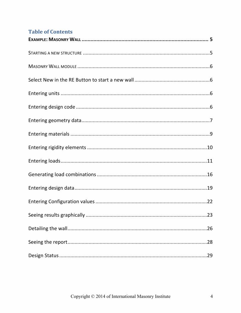
Table of Contents EXAMPLE: MASONRY WALL ...................................................................................... 5
STARTING A NEW STRUCTURE ........................................................................................... 5
MASONRY WALL MODULE ............................................................................................... 6
Select New in the RE Button to start a new wall ...................................................... 6
Entering units ........................................................................................................... 6
Entering design code ................................................................................................ 6
Entering geometry data ............................................................................................ 7
Entering materials .................................................................................................... 9
Entering rigidity elements ...................................................................................... 10
Entering loads ......................................................................................................... 11
Generating load combinations ............................................................................... 16
Entering design data ............................................................................................... 19
Entering Configuration values ................................................................................ 22
Seeing results graphically ....................................................................................... 23
Detailing the wall .................................................................................................... 26
Seeing the report .................................................................................................... 28
Design Status .......................................................................................................... 29
Copyright © 2014 of International Masonry Institute 5
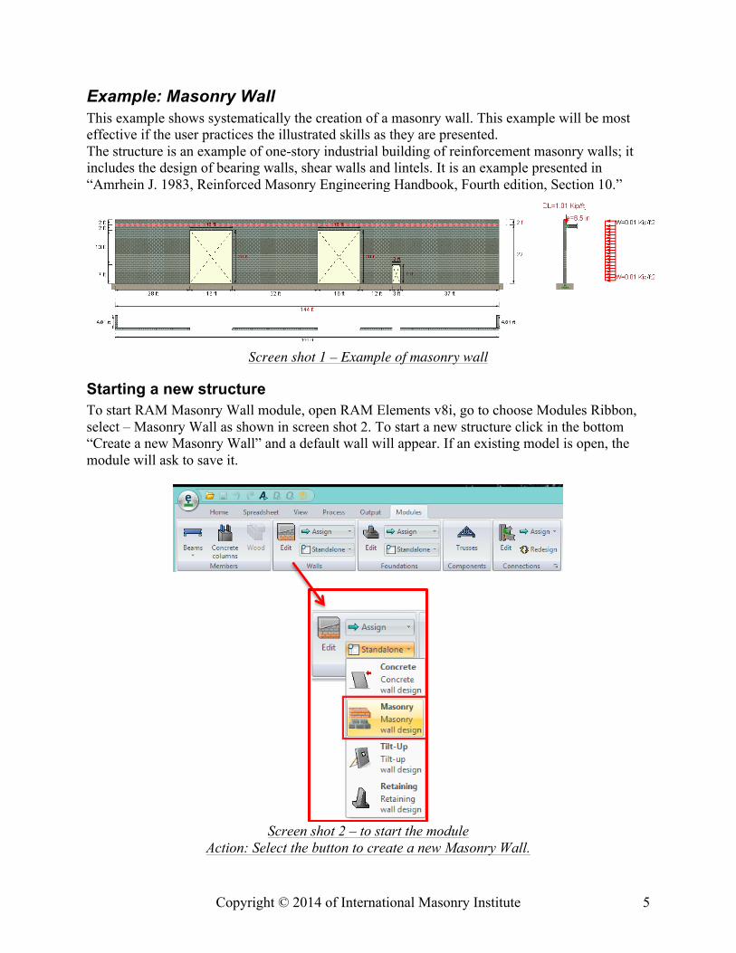
Example: Masonry Wall This example shows systematically the creation of a masonry wall. This example will be most effective if the user practices the illustrated skills as they are presented. The structure is an example of one-story industrial building of reinforcement masonry walls; it includes the design of bearing walls, shear walls and lintels. It is an example presented in “Amrhein J. 1983, Reinforced Masonry Engineering Handbook, Fourth edition, Section 10.”
Screen shot 1 – Example of masonry wall
Starting a new structure To start RAM Masonry Wall module, open RAM Elements v8i, go to choose Modules Ribbon, select – Masonry Wall as shown in screen shot 2. To start a new structure click in the bottom “Create a new Masonry Wall” and a default wall will appear. If an existing model is open, the module will ask to save it.
Screen shot 2 – to start the module
Action: Select the button to create a new Masonry Wall.
Copyright © 2014 of International Masonry Institute 6
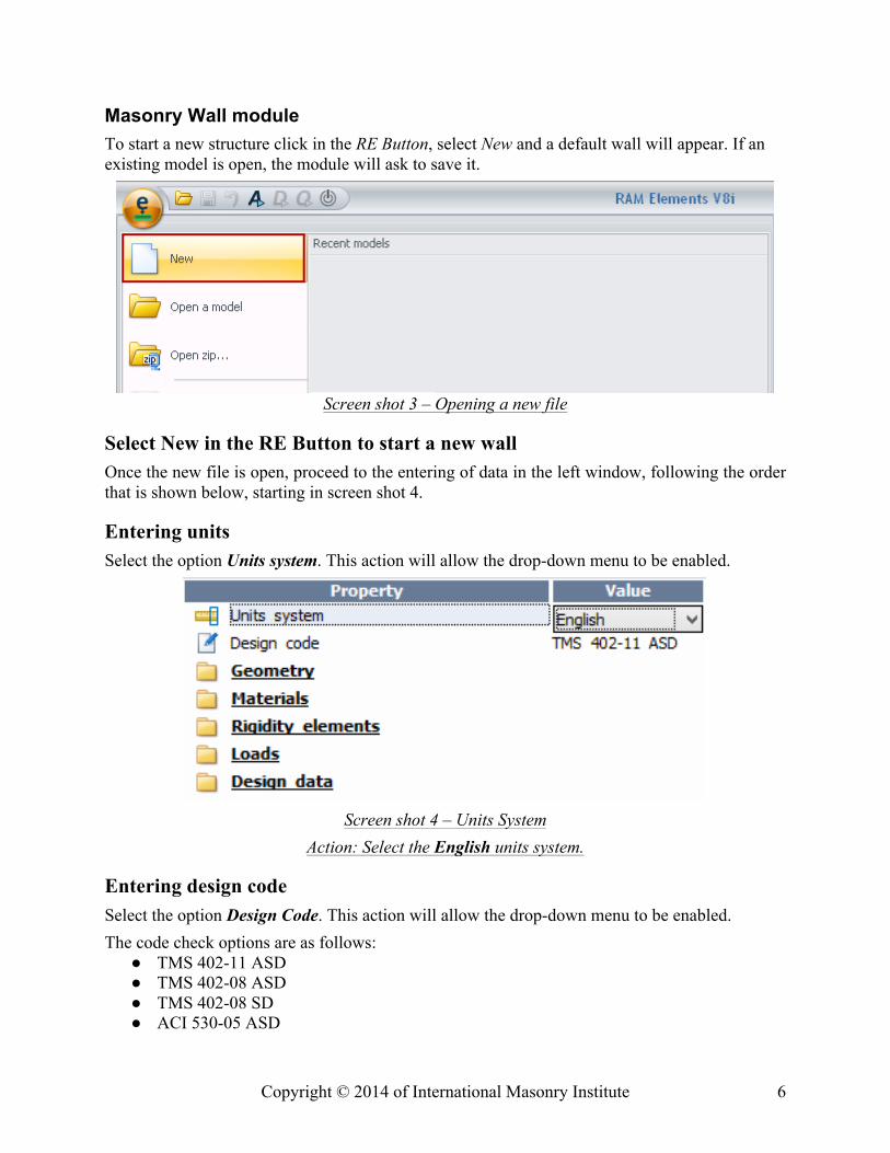
Masonry Wall module To start a new structure click in the RE Button, select New and a default wall will appear. If an existing model is open, the module will ask to save it.
Screen shot 3 – Opening a new file
Select New in the RE Button to start a new wall Once the new file is open, proceed to the entering of data in the left window, following the order that is shown below, starting in screen shot 4.
Entering units Select the option Units system. This action will allow the drop-down menu to be enabled.
Screen shot 4 – Units System
Action: Select the English units system.
Entering design code Select the option Design Code. This action will allow the drop-down menu to be enabled. The code check options are as follows: ● TMS 402-11 ASD ● TMS 402-08 ASD ● TMS 402-08 SD ● ACI 530-05 ASD
Copyright © 2014 of International Masonry Institute 7
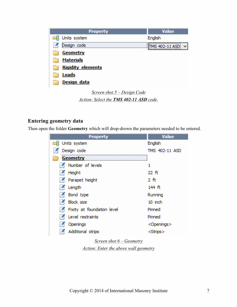
Screen shot 5 – Design Code
Action: Select the TMS 402-11 ASD code.
Entering geometry data Then open the folder Geometry which will drop-drown the parameters needed to be entered.
Screen shot 6 – Geometry
Action: Enter the above wall geometry
Copyright © 2014 of International Masonry Institute 8
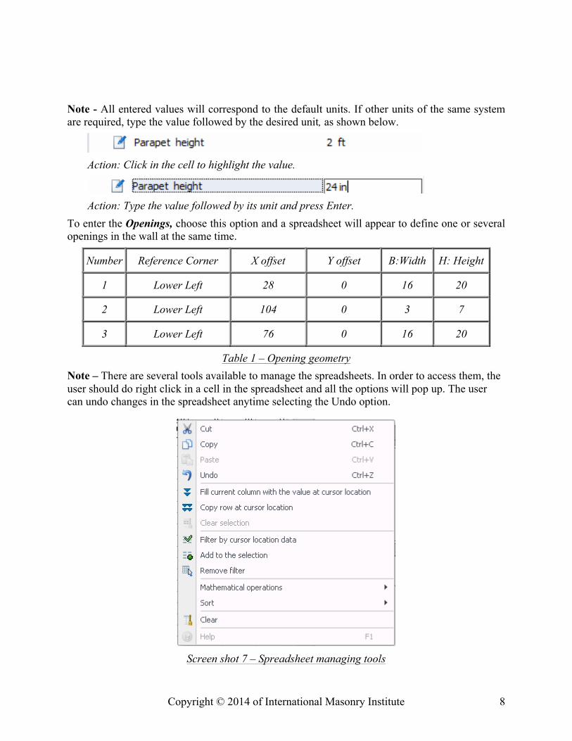
Note - All entered values will correspond to the default units. If other units of the same system are required, type the value followed by the desired unit, as shown below.
Action: Click in the cell to highlight the value.
Action: Type the value followed by its unit and press Enter.
To enter the Openings, choose this option and a spreadsheet will appear to define one or several openings in the wall at the same time.
Number Reference Corner X offset Y offset B:Width H: Height
1 Lower Left 28 0 16 20
2 Lower Left 104 0 3 7
3 Lower Left 76 0 16 20
Table 1 – Opening geometry Note – There are several tools available to manage the spreadsheets. In order to access them, the user should do right click in a cell in the spreadsheet and all the options will pop up. The user can undo changes in the spreadsheet anytime selecting the Undo option.
Screen shot 7 – Spreadsheet managing tools
Copyright © 2014 of International Masonry Institute 9
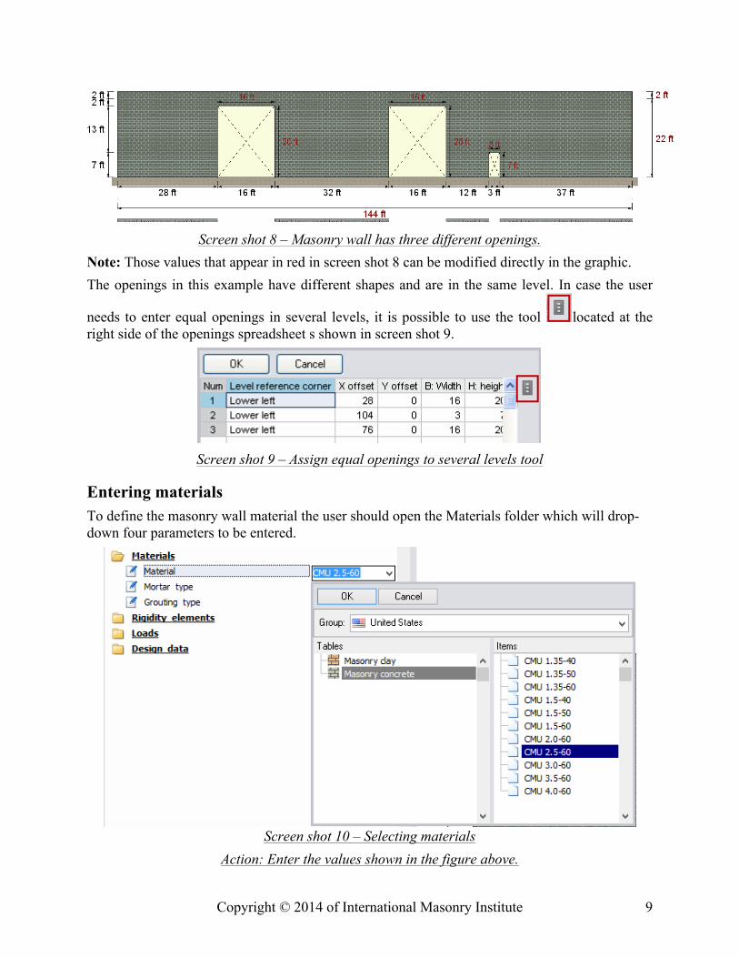
Screen shot 8 – Masonry wall has three different openings.
Note: Those values that appear in red in screen shot 8 can be modified directly in the graphic. The openings in this example have different shapes and are in the same level. In case the user
needs to enter equal openings in several levels, it is possible to use the tool located at the right side of the openings spreadsheet s shown in screen shot 9.
Screen shot 9 – Assign equal openings to several levels tool
Entering materials To define the masonry wall material the user should open the Materials folder which will drop-down four parameters to be entered.
Screen shot 10 – Selecting materials Action: Enter the values shown in the figure above.
Copyright © 2014 of International Masonry Institute 10
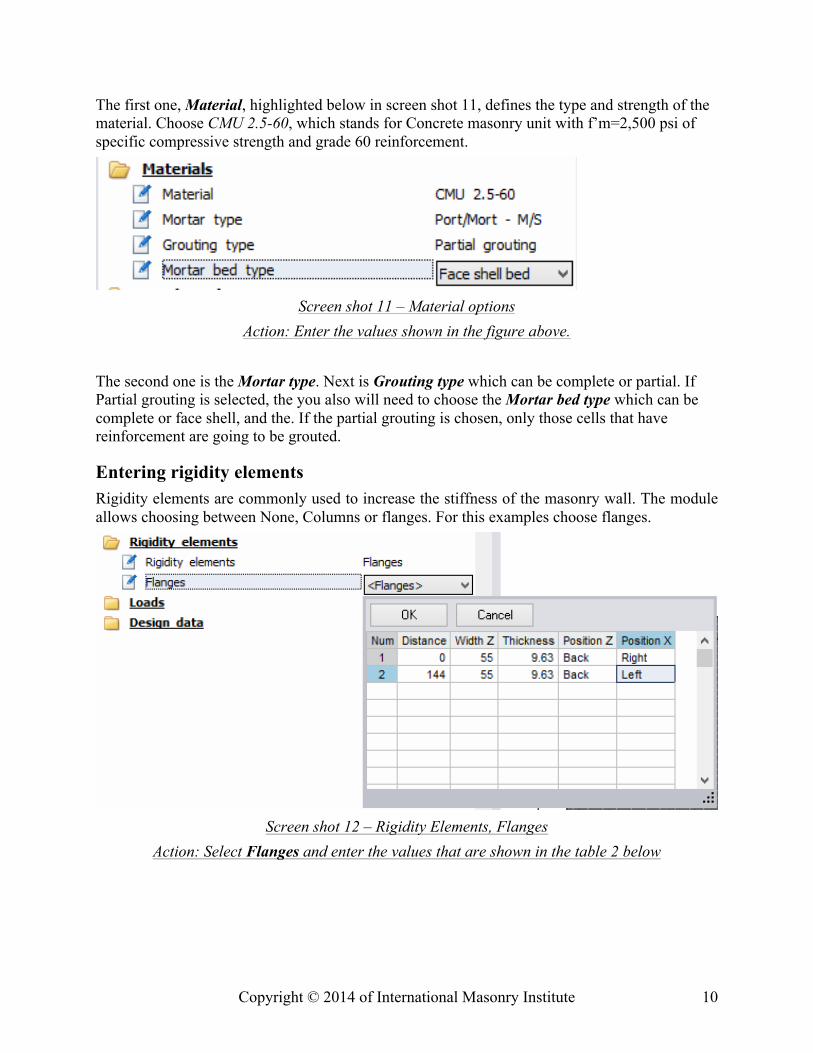
The first one, Material, highlighted below in screen shot 11, defines the type and strength of the material. Choose CMU 2.5-60, which stands for Concrete masonry unit with f’m=2,500 psi of specific compressive strength and grade 60 reinforcement.
Screen shot 11 – Material options
Action: Enter the values shown in the figure above. The second one is the Mortar type. Next is Grouting type which can be complete or partial. If Partial grouting is selected, the you also will need to choose the Mortar bed type which can be complete or face shell, and the. If the partial grouting is chosen, only those cells that have reinforcement are going to be grouted.
Entering rigidity elements Rigidity elements are commonly used to increase the stiffness of the masonry wall. The module allows choosing between None, Columns or flanges. For this examples choose flanges.
Screen shot 12 – Rigidity Elements, Flanges
Action: Select Flanges and enter the values that are shown in the table 2 below
Copyright © 2014 of International Masonry Institute 11
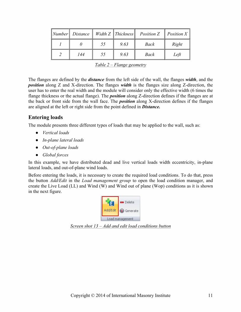
Number Distance Width Z Thickness Position Z Position X
1 0 55 9.63 Back Right
2 144 55 9.63 Back Left
Table 2 – Flange geometry
The flanges are defined by the distance from the left side of the wall, the flanges width, and the position along Z and X-direction. The flanges width is the flanges size along Z-direction, the user has to enter the real width and the module will consider only the effective width (6 times the flange thickness or the actual flange). The position along Z-direction defines if the flanges are at the back or front side from the wall face. The position along X-direction defines if the flanges are aligned at the left or right side from the point defined in Distance.
Entering loads The module presents three different types of loads that may be applied to the wall, such as: ● Vertical loads ● In-plane lateral loads ● Out-of-plane loads ● Global forces
In this example, we have distributed dead and live vertical loads width eccentricity, in-plane lateral loads, and out-of-plane wind loads. Before entering the loads, it is necessary to create the required load conditions. To do that, press the button Add/Edit in the Load management group to open the load condition manager, and create the Live Load (LL) and Wind (W) and Wind out of plane (Wop) conditions as it is shown in the next figure.
Screen shot 13 – Add and edit load conditions button
Copyright © 2014 of International Masonry Institute 12
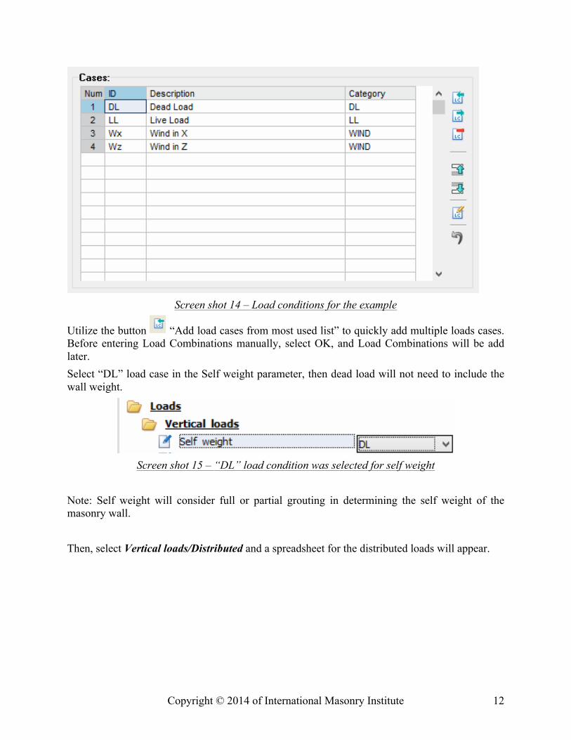
Screen shot 14 – Load conditions for the example
Utilize the button “Add load cases from most used list” to quickly add multiple loads cases. Before entering Load Combinations manually, select OK, and Load Combinations will be add later. Select “DL” load case in the Self weight parameter, then dead load will not need to include the wall weight.
Screen shot 15 – “DL” load condition was selected for self weight
Note: Self weight will consider full or partial grouting in determining the self weight of the masonry wall. Then, select Vertical loads/Distributed and a spreadsheet for the distributed loads will appear.
Copyright © 2014 of International Masonry Institute 13
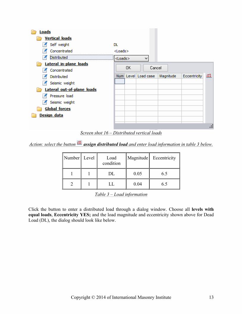
Screen shot 16 – Distributed vertical loads
Action: select the button assign distributed load and enter load information in table 3 below.
Number Level Load condition
Magnitude Eccentricity
1 1 DL 0.05 6.5
2 1 LL 0.04 6.5
Table 3 – Load information Click the button to enter a distributed load through a dialog window. Choose all levels with equal loads, Eccentricity YES; and the load magnitude and eccentricity shown above for Dead Load (DL), the dialog should look like below.
Copyright © 2014 of International Masonry Institute 14
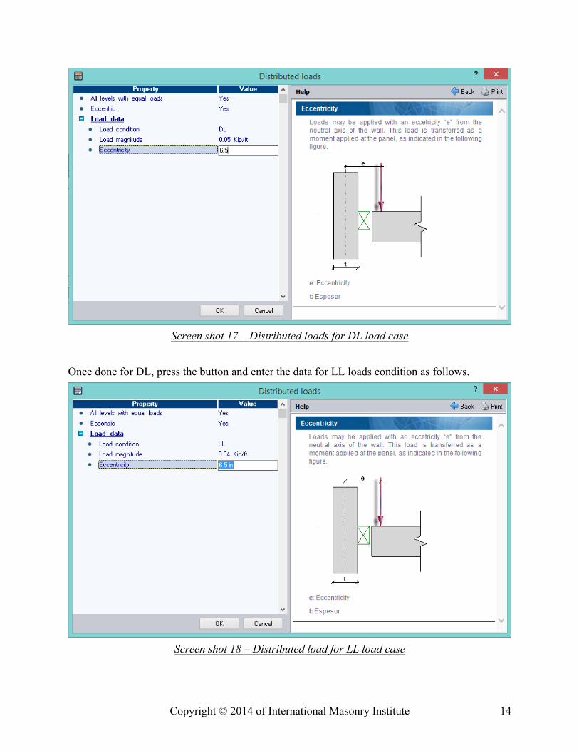
Screen shot 17 – Distributed loads for DL load case
Once done for DL, press the button and enter the data for LL loads condition as follows.
Screen shot 18 – Distributed load for LL load case
Copyright © 2014 of International Masonry Institute 15
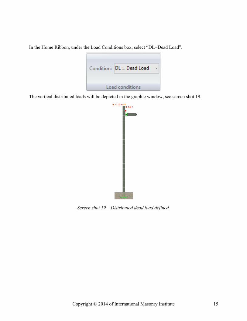
In the Home Ribbon, under the Load Conditions box, select “DL=Dead Load”.
The vertical distributed loads will be depicted in the graphic window, see screen shot 19.
Screen shot 19 – Distributed dead load defined.
Copyright © 2014 of International Masonry Institute 16
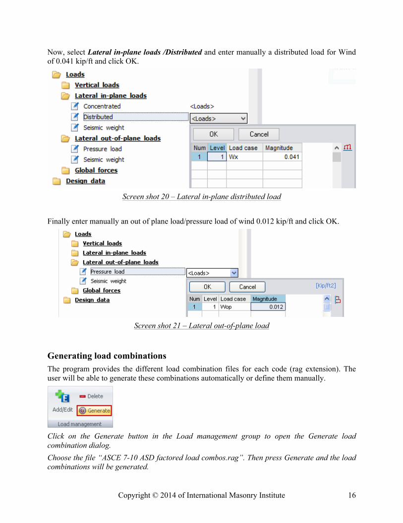
Now, select Lateral in-plane loads /Distributed and enter manually a distributed load for Wind of 0.041 kip/ft and click OK.
Screen shot 20 – Lateral in-plane distributed load
Finally enter manually an out of plane load/pressure load of wind 0.012 kip/ft and click OK.
Screen shot 21 – Lateral out-of-plane load
Generating load combinations The program provides the different load combination files for each code (rag extension). The user will be able to generate these combinations automatically or define them manually.
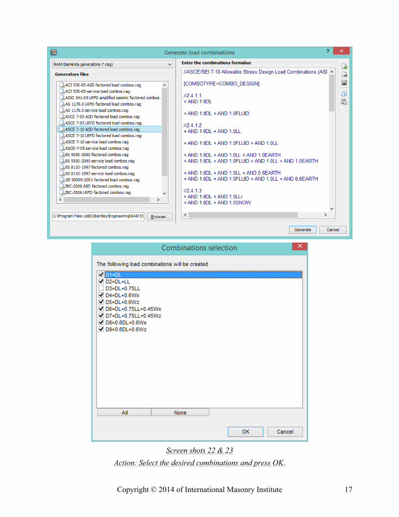
Click on the Generate button in the Load management group to open the Generate load combination dialog. Choose the file “ASCE 7-10 ASD factored load combos.rag”. Then press Generate and the load combinations will be generated.
Copyright © 2014 of International Masonry Institute 17
Screen shots 22 & 23
Action: Select the desired combinations and press OK.
Copyright © 2014 of International Masonry Institute 18
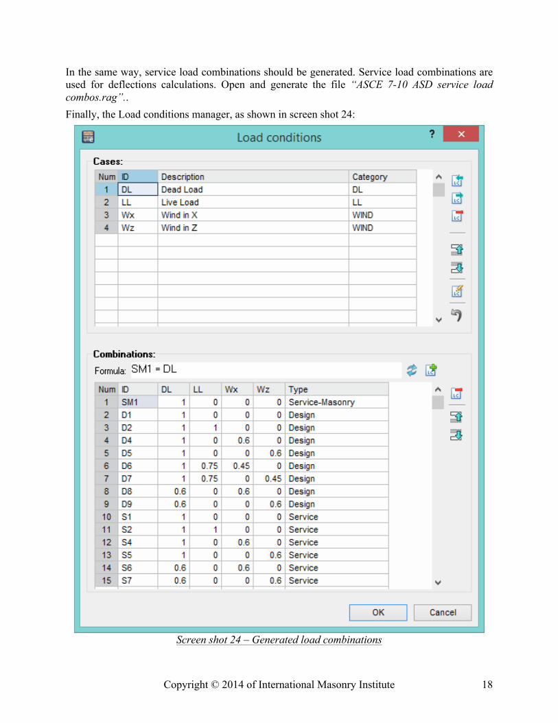
In the same way, service load combinations should be generated. Service load combinations are used for deflections calculations. Open and generate the file “ASCE 7-10 ASD service load combos.rag”.. Finally, the Load conditions manager, as shown in screen shot 24:
Screen shot 24 – Generated load combinations
Copyright © 2014 of International Masonry Institute 19
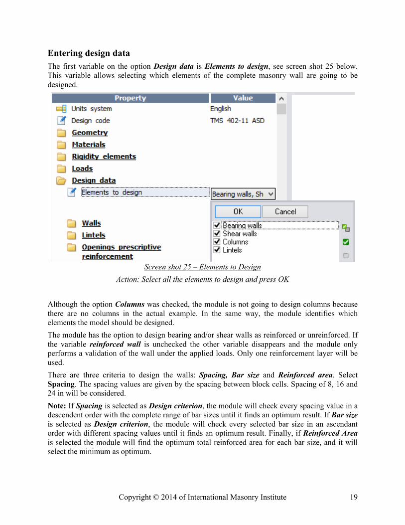
Entering design data The first variable on the option Design data is Elements to design, see screen shot 25 below. This variable allows selecting which elements of the complete masonry wall are going to be designed.
Screen shot 25 – Elements to Design Action: Select all the elements to design and press OK
Although the option Columns was checked, the module is not going to design columns because there are no columns in the actual example. In the same way, the module identifies which elements the model should be designed. The module has the option to design bearing and/or shear walls as reinforced or unreinforced. If the variable reinforced wall is unchecked the other variable disappears and the module only performs a validation of the wall under the applied loads. Only one reinforcement layer will be used. There are three criteria to design the walls: Spacing, Bar size and Reinforced area. Select Spacing. The spacing values are given by the spacing between block cells. Spacing of 8, 16 and 24 in will be considered. Note: If Spacing is selected as Design criterion, the module will check every spacing value in a descendent order with the complete range of bar sizes until it finds an optimum result. If Bar size is selected as Design criterion, the module will check every selected bar size in an ascendant order with different spacing values until it finds an optimum result. Finally, if Reinforced Area is selected the module will find the optimum total reinforced area for each bar size, and it will select the minimum as optimum.
Copyright © 2014 of International Masonry Institute 20
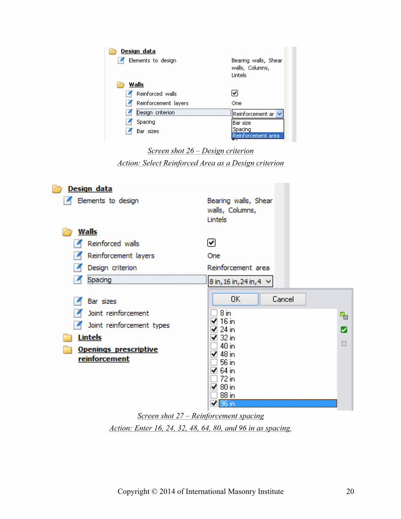
Screen shot 26 – Design criterion
Action: Select Reinforced Area as a Design criterion
Screen shot 27 – Reinforcement spacing Action: Enter 16, 24, 32, 48, 64, 80, and 96 in as spacing.
Copyright © 2014 of International Masonry Institute 21
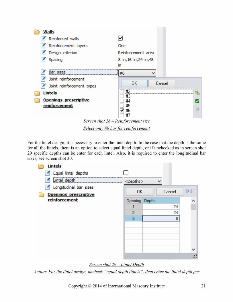
Screen shot 28 – Reinforcement size Select only #6 bar for reinforcement
For the lintel design, it is necessary to enter the lintel depth. In the case that the depth is the same for all the lintels, there is an option to select equal lintel depth, or if unchecked as in screen shot 29 specific depths can be enter for each lintel. Also, it is required to enter the longitudinal bar sizes, see screen shot 30.
Screen shot 29 – Lintel Depth
Action: For the lintel design, uncheck “equal depth lintels”, then enter the lintel depth per
Copyright © 2014 of International Masonry Institute 22
opening
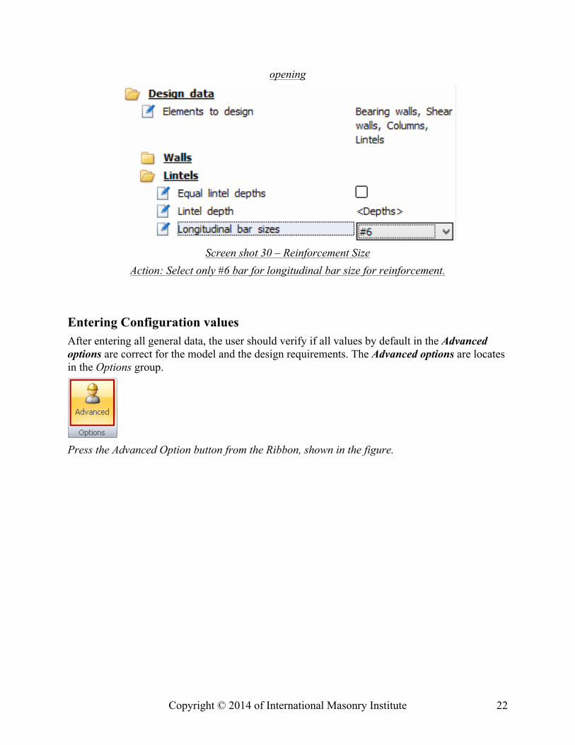
Screen shot 30 – Reinforcement Size
Action: Select only #6 bar for longitudinal bar size for reinforcement.
Entering Configuration values After entering all general data, the user should verify if all values by default in the Advanced options are correct for the model and the design requirements. The Advanced options are locates in the Options group.
Press the Advanced Option button from the Ribbon, shown in the figure.
Copyright © 2014 of International Masonry Institute 23
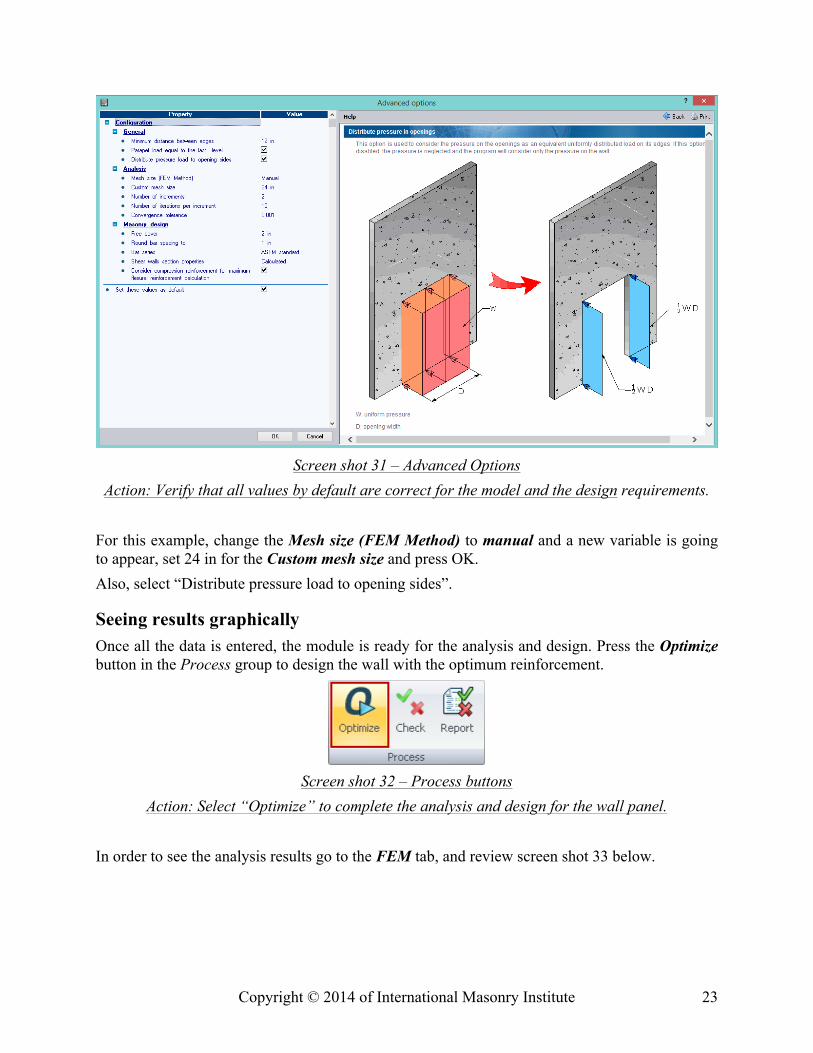
Screen shot 31 – Advanced Options
Action: Verify that all values by default are correct for the model and the design requirements. For this example, change the Mesh size (FEM Method) to manual and a new variable is going to appear, set 24 in for the Custom mesh size and press OK. Also, select “Distribute pressure load to opening sides”.
Seeing results graphically Once all the data is entered, the module is ready for the analysis and design. Press the Optimize button in the Process group to design the wall with the optimum reinforcement.
Screen shot 32 – Process buttons
Action: Select “Optimize” to complete the analysis and design for the wall panel. In order to see the analysis results go to the FEM tab, and review screen shot 33 below.
Copyright © 2014 of International Masonry Institute 24
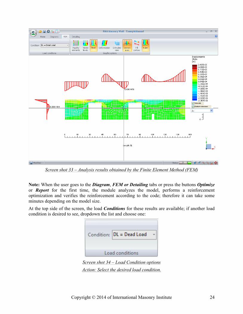
Screen shot 33 – Analysis results obtained by the Finite Element Method (FEM)
Note: When the user goes to the Diagram, FEM or Detailing tabs or press the buttons Optimize or Report for the first time, the module analyzes the model, performs a reinforcement optimization and verifies the reinforcement according to the code; therefore it can take some minutes depending on the model size. At the top side of the screen, the load Conditions for these results are available; if another load condition is desired to see, dropdown the list and choose one:
Screen shot 34 – Load Condition options Action: Select the desired load condition.
Copyright © 2014 of International Masonry Institute 25
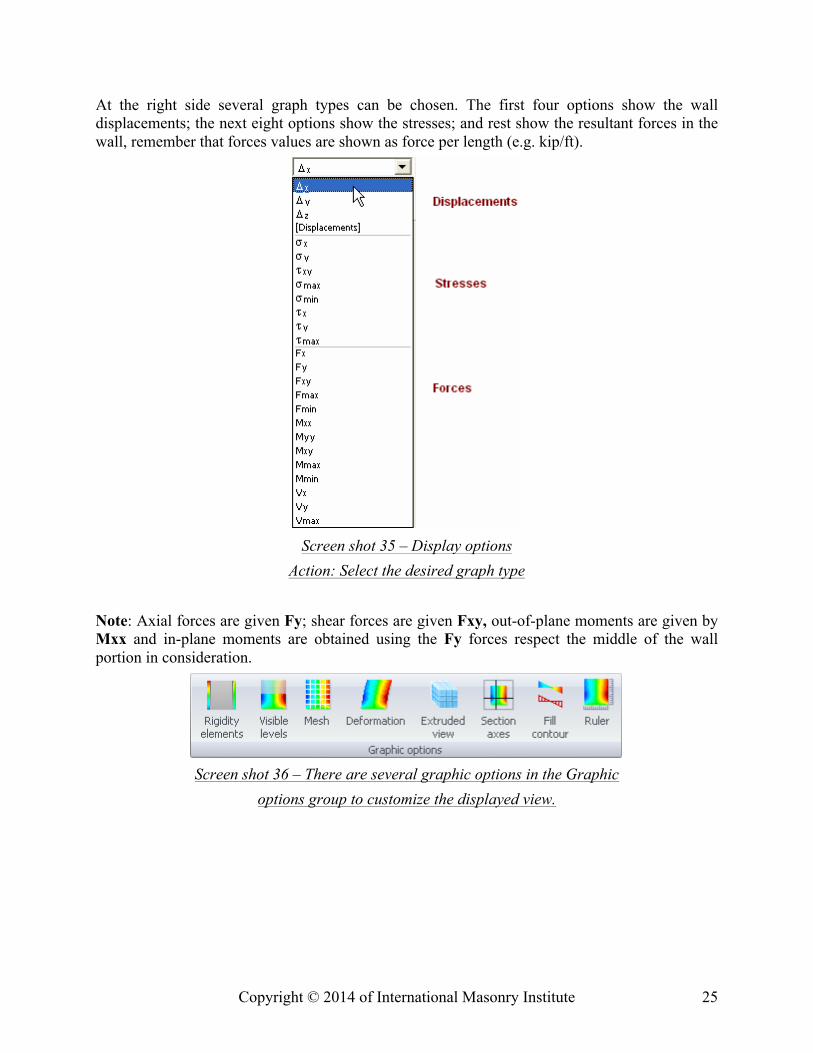
At the right side several graph types can be chosen. The first four options show the wall displacements; the next eight options show the stresses; and rest show the resultant forces in the wall, remember that forces values are shown as force per length (e.g. kip/ft).
Screen shot 35 – Display options
Action: Select the desired graph type Note: Axial forces are given Fy; shear forces are given Fxy, out-of-plane moments are given by Mxx and in-plane moments are obtained using the Fy forces respect the middle of the wall portion in consideration.
Screen shot 36 – There are several graphic options in the Graphic
options group to customize the displayed view.
Copyright © 2014 of International Masonry Institute 26
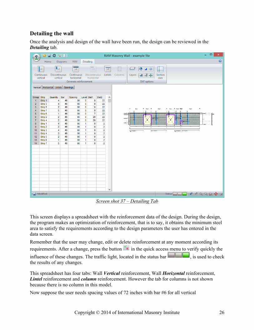
Detailing the wall Once the analysis and design of the wall have been run, the design can be reviewed in the Detailing tab.
Screen shot 37 – Detailing Tab This screen displays a spreadsheet with the reinforcement data of the design. During the design, the program makes an optimization of reinforcement, that is to say, it obtains the minimum steel area to satisfy the requirements according to the design parameters the user has entered in the data screen. Remember that the user may change, edit or delete reinforcement at any moment according its requirements. After a change, press the button in the quick access menu to verify quickly the influence of these changes. The traffic light, located in the status bar , is used to check the results of any changes.
This spreadsheet has four tabs: Wall Vertical reinforcement, Wall Horizontal reinforcement, Lintel reinforcement and column reinforcement. However the tab for columns is not shown because there is no column in this model. Now suppose the user needs spacing values of 72 inches with bar #6 for all vertical
Copyright © 2014 of International Masonry Institute 27
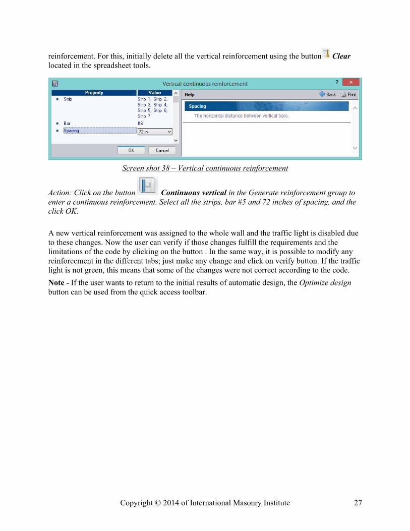
reinforcement. For this, initially delete all the vertical reinforcement using the button Clear located in the spreadsheet tools.
Screen shot 38 – Vertical continuous reinforcement
Action: Click on the button Continuous vertical in the Generate reinforcement group to enter a continuous reinforcement. Select all the strips, bar #5 and 72 inches of spacing, and the click OK. A new vertical reinforcement was assigned to the whole wall and the traffic light is disabled due to these changes. Now the user can verify if those changes fulfill the requirements and the limitations of the code by clicking on the button . In the same way, it is possible to modify any reinforcement in the different tabs; just make any change and click on verify button. If the traffic light is not green, this means that some of the changes were not correct according to the code. Note - If the user wants to return to the initial results of automatic design, the Optimize design button can be used from the quick access toolbar.
Copyright © 2014 of International Masonry Institute 28
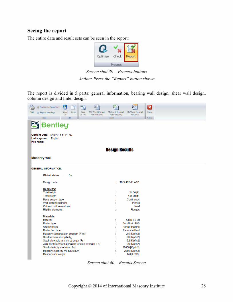
Seeing the report The entire data and result sets can be seen in the report:
Screen shot 39 – Process buttons
Action: Press the “Report” button shown The report is divided in 5 parts: general information, bearing wall design, shear wall design, column design and lintel design.
Screen shot 40 – Results Screen
Copyright © 2014 of International Masonry Institute 29
• General information. This part of the report shows the wall geometry, material, openings, rigidity elements, load conditions, and loads.
• Bearing wall Design. This second part of the report shows the design results of the walls considered as bearing walls. It is subdivided in:
• Bearing wall status and plot • Segment geometry • Vertical reinforcement • Results • Shear wall Design. It shows the design results of the walls considered as shear walls. It is
subdivided in: • Shear wall status and plot • Segment geometry • Vertical and horizontal reinforcement • Results • Column Design. It shows the design results of the columns. It is subdivided in: • Column status and plot • Column geometry • Reinforcement • Results • Lintel Design. It shows the design results of the lintels. It is subdivided in: • Lintel status and plot • Lintel geometry • Reinforcement • Results
Design Status The report presents a general status for bearing walls, shear walls, columns and lintels. There are three possible options:
“OK” when all the elements fulfill the requirements and limitations of the code “Warnings.” when some elements fail one or more limitations of the code. “N.G.” when some elements fail one or more requirements of the code.