international journal of scientific research and reviews · 2019-07-15 · liu3the voltage and...
TRANSCRIPT
P. Loganathan et al., IJSRR 2019, 8(2), 2826-2843
IJSRR, 8(2) April. – June., 2019 Page 2826
Research article Available online www.ijsrr.org ISSN: 2279–0543
International Journal of Scientific Research and Reviews
Performance Evolution of Hybrid Energy Generation and Static Var Compensation for Stability Load Analysis Using Multi-Objective
Partial Swarm Optimization Algorithm
P. Loganathan1* and G. Kathiresan2
1Department of Electrical and Electronics Engineering, Vinayaka Mission’s KirupanandaVariyar Engineering College, Vinayaka Mission’s Research Foundation (Deemed to be University),
Salem-636308, Tamilnadu, India. 2Department of Electrical and Electronics Engineering, Vinayaka Mission’s KirupanandaVariyar
Engineering College, Vinayaka Mission’s Research Foundation (Deemed to be University), Salem-636308, Tamilnadu, India.
ABSTRACT: A wind-solar hybrid power generation system consisting of photovoltaic (PV) modules and
permanent magnet synchronous generator (PMSG) based wind generation controlled by Multi-Objective Partial Swarm Optimization (MOPSO) technique for both converter and inverter for the stability of a grid-connected system. The proposed method improves the power quality without voltage sag and swell. Multi-Objective Partial Swarm Optimization (MOPSO) algorithm was developed to find out the best operating point of a Static VAR Compensator (SVC) for the enhancement of power compensation. Reduces the voltage distortion caused by harmonics. Stabilizes the voltage and diminish the voltage fluctuation and flicker. The application SVC is used for multi-objective power flow that minimizes generation cost, decreasing the voltage deviation, reducing of voltage deviation stability L-Index, minimizing of total power loss and minimizing the installation cost of SVC device by including some of the constraints. Overall the multi-objective optimization will be used for future load flow analysis and effective planning in the power system.
KEYWORD: Harmonics reduction, Multi-Objective Partial Swarm Optimization Algorithm, Static VAR Compensator, Converter, Inverter. *Corresponding author:
P.Loganathan Department of Electrical and Electronics Engineering,
Vinayaka Mission’s KirupanandaVariyar Engineering College,
Vinayaka Mission’s Research Foundation (Deemed to be University),
Salem-636308, Tamilnadu, India.

P. Loganathan et al., IJSRR 2019, 8(2), 2826-2843
IJSRR, 8(2) April. – June., 2019 Page 2827
I. INTRODUCTION A hybrid solar-wind system consists of Photovoltaic array, wind turbine, DC bus, AC bus,
inverter, controller and cables. The PV array and wind turbine work together to compensate for the
load demand. Energy sources when (solar-wind) are abundant, the power generated from the solar, in
the day time it will continue to charge until the battery is fully charged. On different the when
energy sources are poor, the battery will deliver energy to support the PV array and wind turbine to
cover the load conditions until the storage is consumed. The hybrid solar-wind system modeling is
mainly subordinate on the performance of individual components. In order to predict the system
performance, both sources of power generation should be modeled separately and will be combined
to meet the demanding reliability. If the power output forecast from these individual sources is
accurate enough, the resultant combination will deliver power effectively. A hybrid system could be
designed to work either in isolated mode or in grid-connected mode, through power electronic
interface. To ensure the power system security, the OPRPP problem is associated with the
contingency analysis problem. The contingency analysis, which is a well-known function in power
system planning and operation, is used later to predict the contingencies which make system violated
and rank the contingencies according to their relative severity.
Figure 1: Hybrid Wind and Solar Energy System
An outage of a transmission line, capacitor bank or transformer may lead to overloads in
other branches and sudden system voltage rise or drop. The Hybrid multi Particle Swarm
Optimization and Gravitational Search have been used for solving the reactive power planning using
SVC's device. Various critical situations are simulated to prove the effectiveness of the proposed
algorithm and to ensure the viability of the power system in contingency scenarios. The locations of
the SVC's devices considering voltage security are determined using three different stability indexes
namely, Fast Voltage Stability Index (FVSI), Line stability index and Line Stability Factor. The

P. Loganathan et al., IJSRR 2019, 8(2), 2826-2843
IJSRR, 8(2) April. – June., 2019 Page 2828
simulation outcome shows the high performance of MOPSO algorithm on minimizing the
transmission power losses and on improving the real power and annual cost savings. The analyses of
the results are very promising since the main objectives of the proposed technique is reduced the
power loss, and harmonics are proposed, controller.Hybrid power systems are a rapidly growing
area of research. Not only domestic, commercial and industrial loads are studied to be switched to
these systems but implemented effectively in automobiles. Renewable energy resources are solar
power, wind power, tidal power, geothermal power, wave power, and biomass. They are persistent,
naturally renewing themselves and environment-friendly. This is why they are called green energy
resources. Unrenewable conventional energy resources such as oil, coal, gas, etc. decrease slowly
with time. The main feature renewable energy systems are to combine two or can address efficiency,
reliability, emissions and economic limitations of single renewable energy source. Themethodology
aims to find the configuration, among a set of system components, which meets the desired system
reliability requirements with the lowest value of costs.
II. LITERATURE REVIEW The proposed approach is compared to previous methods using experimental measurements.
Bilal Khan1their operation is accompanied, with fluctuating wind speeds, transients, and abrupt
power variations. The voltage at the point of common coupling with the grid, violates stable voltages
limits, even during low speeds. In this paper static compensators (STATCOM), and static VAR
compensators (SVC) has been used to improve the transient stability of wind farms based on fixed
speed wind turbines with adjustable rotor resistance. Li Wang2this model presents the stability
improvement of a multi machine power system connected with a large-scale hybrid wind-
photovoltaic (PV) farm using an energy-storage unit based on supercapacitor (SC). The operating
characteristics of the hybrid wind-PV farm are simulated by an equivalent aggregated 300-MW
wind-turbine generator (WTG) based on permanent-magnet synchronous generator.Yanzhang
Liu3the voltage and reactive power control strategy uses the grid-connected inverters and static VAR
compensation (SVC) device as flexible and controllable source of reactive power to regulate the
voltage and reactive power of large-scale PV power plants.
Avudai Lakshmi4 These voltage fluctuationscan be eliminated with the help of advanced
reactive power compensation devices such as SVC (Static VAR Compensator), STATCOM (Static
Synchronous Compensator) and DVR (Dynamic Voltage Restorer). In this model, ST ATCOM is
used as a compensating device. ST A TCOM is a static synchronous generator operated as a parallel
connection static reactive compensator. Yeonho Ok5the phenomenon of voltage risewhen the
renewable energy power plants are connected to the distribution grid is analyzed. For analysis of

P. Loganathan et al., IJSRR 2019, 8(2), 2826-2843
IJSRR, 8(2) April. – June., 2019 Page 2829
voltage rise phenomenon, the actual operation data with some kinds of renewable energy power
plants such as small hydro power plant, solar power plant and wind power plant are gathered
firstly.Hassan Zahboune6 the system of study contains a windturbine (asynchronous generator)
connected to an AC 1 DC converter, a static VAR compensator (SVC) represents a variable capacity
and an LC filter to supply a resistive load.Yousef Mahmoud7an accurate model is essential when
designing photovoltaic(PV) systems. PV models rely on a set of transcendental nonlinear equations
which add to the model complexity. This letter proposes a simple and easy-to-model approach for
implementation in simulations of PV systems.
Joanne Hui8 this model presents a new system configurationof the front-end rectifier stage for
a hybrid wind/photovoltaic energy system. This configuration allows the two sources to supply the
load separately or simultaneously depending on the availability of the energy sources. The inherent
nature of this Cuk-SEPIC fused converter, additional input filters are not necessary to filter out high
frequency harmonics. Harmonic content is detrimental for the generator lifespan, heating issues, and
efficiency.Bharanikumar9 a Wind Generator System that employs a boostchopper and a permanent
magnet synchronous generator is studied. By replacing the main circuit of generator and boost
chopper with the equivalent circuit, the power and DC output voltage are obtained as a function of
duty ratio of the boost chopper and generator rotational frequency. Dumitru Cristian
Drago10Virtually all regions of the worldhave renewable resources of one type or another. By this
point of view studies on renewable energies focuses more and more attention. The present model
intends to present different mathematical models related to different types of renewable energy
sources such as: solar energy and wind energy. It is also presented the validation and adaptation of
such models to hybrid systems working in geographical and meteorological conditions.
III. PROPOSED SYSTEM The proposed method presents, a wind-solar hybrid power generator system consisting of
photovoltaic (PV) modules controlled by Multi-Objective Partial Swarm Optimization (MOPSO)
method and connected to a DC-DC boost converter, a grid-connected wind turbine coupled with a
permanent magnet synchronous generator (PMSG) and connected to a back-to-back converter and
also a bidirectional DC-DC converter, and finally an energy storage module (batteries) connected to
a bidirectional DC-DC converter has been modeled, implemented and discussed in this work to
achieve an efficient and cost-effective system configuration so that renewable energy power sources
could improve the life of people in both urban and remote residential areas. Additionally, a device
Static VAR Compensators (SVCs) have been used to improve both the power angle stability of

P. Loganathan et al., IJSRR 2019, 8(2), 2826-2843
IJSRR, 8(2) April. – June., 2019 Page 2830
generators and the voltage behavior at the SVC location. SVC address unbalanced voltage problems
in distribution, sub-transmission and transmission networks.
Figure 2: Block Diagram
The word photovoltaic combines two terms photo means light and voltaic means voltage.
Photovoltaic energy is obtained from sunlight in the form of solar energy. Wind power is the
management of kinetic flow through wind turbines to kinetic power generators for electric power.
Wind energy, as an option to burning fossil fuels, is abundant, renewable, generally distributed,
clean, creates no harmful gas emissions during operation, consumes no water, and uses little
land.Both the PV and wind system can be output improved by using DC-DC boost converters.The dc
bus voltage controllers are designed based on the assumption that the dc bus is purely capacitive.
Therefore, a purely capacitive dc bus with capacitance equal to the total converter dc link
capacitance is analyzed. Multi-Objective Partial Swarm Optimization (MOPSO) algorithm is used to
reduce harmonics distortion and noises. Finally, the improved voltage has been inverted and given to
the ac grid.
3.1 Solar Power The word photovoltaic combines two terms photo means light and voltaic means voltage.
Photovoltaic energy is obtained from sunlight in the form of solar energy. The sunlight is made to be
focused on solar panels which have the ability to convert the solar energy to electrical energy. The
conversion of solar energy to electrical energy is done by solar cells of the solar panel. A
solar panel is a compilation of solar photovoltaic modules electrically connected and attached on a
supporting arrangement. A photovoltaic module is a packaged, combined arrangement of solar cells.

P. Loganathan et al., IJSRR 2019, 8(2), 2826-2843
IJSRR, 8(2) April. – June., 2019 Page 2831
Figure 3: Equivalent Circuit of Solar Cell
The solar panel can be employed as a segmentof a larger photovoltaic system to generate and
generate electricity in commercial and residential applications. ItsDC output power rates each module
under standard test conditions (STC), and typically ranges from 100 to 320 watts. The efficiency of a
module limits the area of a module given the same rated outputefficient module will have twice the area
of adynamicmodule. A single solar module can provide only a limited amount of power; most
installations contain multiple modules. A photovoltaic system typically includes a panel or an array of
solar modules, an inverter, and sometimes a battery and/or solar tracker and interconnectionwiring.
3.2 Wind Energy
Figure 4: Wind Turbine
Wind turbines correspondingly generate electrical power as all other generation technologies.
The only variation is in the source of the mechanical power satisfied with the electrical generator.
Wind energy is a special form of kinetic energy in the air as it flows. Wind energy can be either
converted into electrical energy by power converting machines or directly used for pumping water,
sailing ships, or grinding gain. Kinetic energy exists whenever an object of a given mass is in motion
with a translational or rotational speed. Wind power density is a comprehensive index in evaluating

P. Loganathan et al., IJSRR 2019, 8(2), 2826-2843
IJSRR, 8(2) April. – June., 2019 Page 2832
the wind resource at a particular site. It is the available wind power in airflow through a
perpendicular cross-sectional unit area in a unit time period.
3.3 DC to DC Boost Converter: The DC-DCconverters are used to convert the unregulated dc input to a controlled dc output
at the desired voltage level. They generally accomplish the conversion by employing a dc voltage
across an inductor or transformer for a duration of time (usually in the 20 kHz to 5 MHz range)
which begins current to passing through it and store energy magnetically, then switching this voltage
off and producing the stored energy to be assigned to the voltage output in a controlled manner.
Figure 5: Boost Converter Circuit Diagram
The output voltage is controlled by regulating the ratio of on/off time. This is achieved using
switched mode circuits whose elements dissipate negligible power. Pulse width modulation provides
control and regulation of the total output voltage. It is considered as the response of the power
supply. Thus it will change the overall execution of the power supply system.
3.4 AC to DC Converter The AC to DC converts the AC voltage to pulsating DC, which is smoothened by the
smoothing circuit. The output voltage of the Energy supply is assumed to remain constant against
variations in the load current or variations in input voltage.
Figure 6: AC to DC Converter
G
Inductor
D
S-
MOSFET
+
Diode
Capacitor
+
Battery-
+
-
Load

P. Loganathan et al., IJSRR 2019, 8(2), 2826-2843
IJSRR, 8(2) April. – June., 2019 Page 2833
This is performed by using a suitable voltage regulator.This property of diode presents it an
essential component of DC power supplies which are used to power electronic systems and
circuits.The transformer is utilized to step down the AC mains voltage. The transformer also presents
electrical isolation to the electronic system from AC mains.
3.5 DC to AC Inverter: An inverter is an electronic device or that changes direct current (DC) to alternating current
(AC). An inverter transforms the DC voltage to an AC voltage. In most cases, the input DC voltage
is usually lower while the output AC is equal to the grid supply voltage of either 120 volts, or 240
Volts depending on the country. The inverter may be built as standalone equipment for applications
such as solar power, or to work as backup power supply from batteries which are charged separately.
There are several types of inverters based on the shape of the switching waveform. These have
varying circuit configurations, efficiencies, advantages, and disadvantages.
Figure 7: Simple H Bridge Inverter
An inverter provides an AC voltage from dc power sources and is useful in power electronics
and electrical equipment rated at the ac mains voltage. In addition, they are widely used in the
switched mode power supplies inverting stages.Inverters are used to eliminate the bulky transformer
required in case of conventional multi-phase inverters, clamping diodes required in case of diode-
clamped inverters and flying capacitors required in case of flying capacitor inverters. But these
require a large number of isolated voltages to supply each cell.
3.6 Static VAR Compensator: The static compensators are used in a power system to increase the power transmission
capacity with a given network, from the generators to the loads. Since static compensators cannot
generate or absorb real power, the power transmission of the system is affected indirectly by voltage
control. That is, the reactive output power (capacitive or inductive) of compensator is varied to

P. Loganathan et al., IJSRR 2019, 8(2), 2826-2843
IJSRR, 8(2) April. – June., 2019 Page 2834
control the voltage at given terminals of the transmission network so as to maintain the desired
power flow under possible system disturbances and contingencies. SVCs are part of the transmission
system device family, regulating voltage and stabilizing the system. Unlike a synchronous condenser
which is a rotating electrical machine, a "static" VAR compensator has no significant moving parts
(other than internal switchgear). Prior to the invention of the SVC, power factor compensation was
the preserve of large rotating machines such as synchronous condensers or switched capacitor banks.
The SVC is an automated impedance matching device, designed to bring the system closer to
unity power factor. SVCs are used in two main situations: Connected to the power system, to
regulate the transmission voltage Connected near large industrial loads, to improve power quality
("Industrial SVC"). In transmission applications, the SVC is used to regulate the grid voltage. If the
power system's reactive load is capacitive (leading), the SVC will use thyristor controlled reactors to
consume vars from the system, lowering the system voltage. Under inductive (lagging) conditions,
the capacitor banks are automatically switched in, thus providing a higher system voltage. By
connecting the thyristor controlled reactor, which is continuously variable, along with a capacitor
bank step, the net result is continuously-variable leading or lagging power. SVC is the preferred
mechanism for dynamic reactive power support in high voltage transmission grids. To its essential
capability for high-speed, cycle-by-cycle control of VAR, it will counteract the often hazardous
voltage depressions that develop in conjunction with faults in the grid. These highly dynamic events,
where the ever-increasing use of induction motors (like those in various units and wind power
turbine-generators) stresses the grid, will need an SVC to maintain the grid voltage and safeguard the
fault ride-through capability.
Figure 8: Static VAR Compensator
An SVC can increase power system transmission and distribution performance in a number
of ways. Installing a static VAR compensator at one or more suitable points in the network can
increase transfer capability and diminish losses while sustaining a balance voltage profile under

P. Loganathan et al., IJSRR 2019, 8(2), 2826-2843
IJSRR, 8(2) April. – June., 2019 Page 2835
different grid conditions. The dynamic stability of the grid can also be enhanced, and active power
oscillations mitigated.
Often the SVC slope setting must be represented to properly simulate system performance.
Coordination and interaction with other WCs and slower-acting voltage control equipment are
studied. Power flow simulation is the primary tool for determining appropriate slope settings.
Representation of the slope is essential in the case of weak systems. Because SVCs are sited at
critical locations in the network, and because of the regulation of transmission (high side) voltage,
representation of SVC slope is usually more important than representation of generator slope. For
tertiary-connected SVCs, the transformer representation is required.
Figure 9: SVC models with slope representation using conventional power flow W busses.
The real power flow through the transformer as well as the SVC voltage regulation must be
modelled correctly. If the SVC coupling transformer is explicitly represented, the SVC model
(steady state or dynamic) must be adjusted so the correct range of reactive power is delivered to the
high voltage bus. Most models and data sets presently used are based on susceptance current active
power limits at the high voltage bus.
3.7 MOPSO Controller: In this work, Multi-Objective Partial Swarm Optimization (MOPSO) algorithm was
developed to find out the best operating point of a Static VAR Compensator (SVC) for the
enhancement of power compensation. This technique is used to reduce harmonics distortion and
noises. Finally, the improved voltage has been inverted and given to the ac grid. The features of the
proposed topology are the inherent nature of these two converters eliminates the need for separate
input filters for PFC it can support step up/down operations for each renewable source (can support
wide ranges of PV and wind input) realized for each source individual and simultaneous operation is
supported.

P. Loganathan et al., IJSRR 2019, 8(2), 2826-2843
IJSRR, 8(2) April. – June., 2019 Page 2836
IV. CIRCUIT DIAGRAM:
Figure 10: Circuit Diagram
In this system, the solar and wind power is used to the system but the output power is not
stable, so in this system implement the Multi-Objective Partial Swarm Optimization
Algorithm (MOPSO) technique and get the better performance of the system.
The controller is provided switching pulse of the converter and inverter switches. And also
the Static VAR Compensator is used to the output side of the system if any unbalance
condition occurs in the load side the SVC is compensated the output voltage. And also this
model reduces the total harmonics distortion and increase efficiency.
P. Loganathan et al., IJSRR 2019, 8(2), 2826-2843
IJSRR, 8(2) April. – June., 2019 Page 2837
4.1 Hardware Model of Proposed System
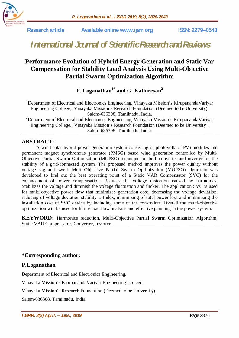
Figure 11: Hardware Model for the Proposed System.
Figure 11 represents the proposed Hardware for the hybrid energy generation and static
compensation for stability load analysis.The model consists of solar power, DC-DC converter,
Boost converter, Inverter, Solar Panel, PIC controller and current transformer and load system.
At the initial stage of operation the battery is connected to the solar panel for charging whenever
the solar is available, the wind system is converted AC to DC and directly connected DC Bus.
The DC Bus is connected to the connected to the inverter. The inverter is Converted DC-AC
voltage will give to the step up transformer it increases the voltage up to (12-230)V it access the
Load system
If additional load is added into the circuit SVC is provide feedback to the PIC16f877A controller.
The controller accelerate the PWM to the converter for proper voltage stabilization. Hence the
load hybrid power Stabilization will access the energy sources into load condition.
P. Loganathan et al., IJSRR 2019, 8(2), 2826-2843
IJSRR, 8(2) April. – June., 2019 Page 2838
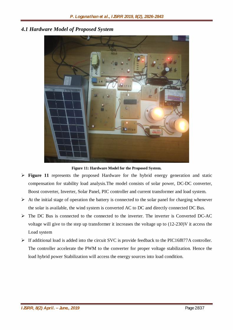
4.2 Hardware Tabulation Output
Hardware Specification Input
Ranges
Output
Ranges
Solar Input power 11v 13v
Battery Input power 12V 1.5A
Microcontroller PIC (16f877a) 5V DC 5V DC
Rectifier Input power 12V AC 12V DC
Inverter Output power 12V DC 12V AC
Boost converter Regulating power 12V 0-25v
Transformer step-up 24VAC 230VAC
Load Load 230V 2A
Load Load 230V 3A
V. RESULT AND DISCUSSION: The present modeling approach of a Mat lab-based toolbox for developing and testing the
Hybrid Energy Generation using Multi-Objective Partial Swarm Optimization. Algorithm (MOPSO)
under various operational conditions. The proposed model is developed in MATLAB environment.

P. Loganathan et al., IJSRR 2019, 8(2), 2826-2843
IJSRR, 8(2) April. – June., 2019 Page 2839
Figure 12: Simulation for the Proposed Method
The above figure 12 shows the overall simulation of the proposed method. The simulation
diagram which represents power flow between the generating to load. The Power has some of the
variations in the load side. Its need to be optimized by the Multi-Objective Partial Swarm
Optimization. Algorithm proposed algorithm method.
Figure 13: Solar Output Waveform
The above figure 13 shows PV (solar) output. PV generated DC voltage up to 100 V. This
output DC voltage is applied to boost converter.

P. Loganathan et al., IJSRR 2019, 8(2), 2826-2843
IJSRR, 8(2) April. – June., 2019 Page 2840
Figure 14: Solar Boost Converter Output Waveform
The above figure 14 shows the Boost converter output waveform. PV generated DC voltage
is low, so the boost converter increases the PV output voltage up to 300 Volts.
Figure 15: Wind Turbine Output Waveform
The above figure 15 shows the wind turbine output waveform. Wind generates AC voltage,
and it applied to AC to DC converter and converts AC to DC voltage.

P. Loganathan et al., IJSRR 2019, 8(2), 2826-2843
IJSRR, 8(2) April. – June., 2019 Page 2841
Figure 16: Wind Boost Converter Output Waveform
The above figure 16 shows the boosted voltage of the wind turbine output waveform. This
output voltage is increased by DC to DC boost converter circuit.
Figure 17: Overall Simulation Output Waveform
Figure 18: THD Analysis
The THD analysis of the proposed system and it is essential to monitor the output voltage, in
this system Total Harmonics Distortion is 11.84%.
P. Loganathan et al., IJSRR 2019, 8(2), 2826-2843
IJSRR, 8(2) April. – June., 2019 Page 2842
5.1 Scope:
Less number of harmonics and Very high reliability.
Long term sustainability and also High energy output.
Distributed generation applications
Constant speed and variable speed wind energy conversion system
VI. CONCLUSION: In this work, a new PV-wind turbine hybrid power system was designed, modeled and
implemented using the MATLAB/Simulink software package for smart grid applications. As the
available power from the proposed PV system is highly dependent on solar radiation, to overcome
this deficiency, the PV system was integrated with the wind turbine system. The dynamic behavior
of the proposed model was examined under different operating conditions. Solar irradiance, and
wind speed data were gathered for a grid-connected wind-solar power system installed in a
residential area. The proposed algorithm gives better output results over then existing algorithm. The
developed system and its control strategy exhibited excellent performance. The proposed model
offers a proper tool for smart grid performance optimization.
VII. REFERENCES 1. Bilal Khan, Mahmoud Kassas, “FSIG-Based Wind Power Plant Transient Stability Margin
Improvement, a STATCOM/SVC Comparison” in IEEE Texas Power and Energy
Conference, 2019.
2. Li Wang, Quang-Son VO, Anton V. Prokhorov, “Stability Improvement of A Multi machine
Power System Connected With A Large Scale Hybrid Wind-Photovoltaic Farm Using A
Supercapacitor" IEEE Transactions on Industry Applications, 2018; 0093-9994.
3. Yanzhang Liu, Lei Zhang, “Study on Control Characteristic of Grid-connected Solar
Photovoltaic Plant Based on Simulation” in international conference on Electric Utility
Deregulation and Restructuring and Power Technologies, 2015.
4. B. Avudai Lakshmi, R. Karpagam, “Resonant Controller Based STATCOM Used in Wind
Farms to Mitigate Power Quality Issues” in International Conference on Electrical, Computer
and Communication Technologies, 2015.
5. Yeonho Ok, Jaeho Choi, “Analysis of Voltage Rise Phenomenon in Distribution Lines
Associated with Grid-Connected Renewable Energy System” in International Conference on
Power Electronics, 2015.

P. Loganathan et al., IJSRR 2019, 8(2), 2826-2843
IJSRR, 8(2) April. – June., 2019 Page 2843
6. Hassan Zahboune, SmailZouggar, “The Voltage Regulation of Asynchronous Wind Turbine
Using a SVC” in International Renewable and Sustainable Energy Conference, 2014; 17-19,.
7. Mahmoud Et Al.," A Simple Approach to Modeling and Simulation of Photovoltaic
Modules," IEEE Transactions on Sustainable Energy, January 2012; 3(1).
8. A. Bakhshai Et Al., "A Hybrid Wind-Solar Energy System: A New Rectifier Stage
Topology" IEEE Magazine, July 2010.
9. R. BharanikumarAnd A. Nirmal Kumar, “Analysis of Wind Turbine Driven Pm Generator
with Power Converters" International Journal of Computer and Electrical Engineering,
August 2010; 2(4)
10. D. C. Drago and G. Adrian, “Modeling of Renewable Hybrid Energy Sources" Scientific
Bulletin of the Petru Maior University of Tirgu Mures, 2009; 6
11. J. Hui, "An Adaptive Control Algorithm for Maximum Power Point Tracking for Wind
Energy Conversion Systems "Department Of Electrical And Computer Engineering, Queen's
University, December 2008.
12. S. Jain and V. Agarwal, "An Integrated Hybrid Power Supply for Distributed Generation
Applications Fed By Nonconventional Energy Sources" IEEE Transactions on Energy
Conversion, June 2008; 22(2)
13. Kim Et Al., "Dynamic Modeling and Control of A Grid-Connected Hybrid Generation
System with Versatile Power Transfer" IEEE Transactions on Industrial Electronics, April
2008; 55(4).
14. Chen Et Al., “Multi-Input Inverter for Grid-Connected Hybrid Pv/Wind Power System" IEEE
Transactions on Power Electronics, May 2007; 22.
15. R. Billinton and R. Karki, "Capacity Expansion of Small Isolated Power Systems Using PV
and Wind Energy" IEEE Transactions on Power Systems, November 2001; 1