international journal of engineering and advanced ...iv. working of rocket a rocket engine, or...
TRANSCRIPT

International Journal of Engineering and Advanced Technology (IJEAT)
ISSN: 2249 – 8958, Volume-4 Issue-6, August 2015
14
Published By:
Blue Eyes Intelligence Engineering
& Sciences Publication Pvt. Ltd.
CFD Analysis on a Different Advanced Rocket
Nozzles
Munipally Prathibha, M. Satyanarayana Gupta, Simhachalam Naidu
Abstract— The reduction of Earth-to-orbit launch costs in
conjunction with an increase in launcher reliability and
operational Efficiency is the key demands on future space
transportation systems, like single-stage-to-orbit vehicles (SSTO).
The realization of these vehicles strongly depends on the
performance of the engines, which should deliver high
performance with low system complexity. Performance data for
rocket engines are practically always lower than the theoretically
attainable values because of imperfections in the mixing,
combustion, and expansion of the propellants. The main part of
the project addresses different nozzle concepts with improvements
in performance as compared to conventional nozzles achieved by
Different Mach numbers, thus, by minimizing losses caused by
over- or under expansion. The design of different nozzle shapes
and flow simulation is done in gambit and fluent software’s
respectively for various parameters
Keywords: launcher reliability, future space transportation
systems, theoretically attainable, mixing, combustion, and
expansion.
I. INTRODUCTION
A nozzle is a device designed to control the direction or
characteristics of a fluid flow (especially to increase velocity)
as it exits (or enters) an enclosed chamber. A nozzle is often a
pipe or tube of varying cross sectional area and it can be used
to direct or modify the flow of a fluid (liquid or gas). Nozzles
are frequently used to control the rate of flow, speed,
direction, mass, shape, and/or the pressure of the stream that
emerges from them. A jet exhaust produces a net thrust from
the energy obtained from combusting fuel which is added to
the inducted air. This hot air is passed through a high speed
nozzle, a propelling nozzle which enormously increases its
kinetic energy. The goal of nozzle is to increase the kinetic
energy of the flowing medium at the expense of its pressure
and internal energy. Nozzles can be described as convergent
(narrowing down from a wide diameter to a smaller diameter
in the direction of the flow) or divergent (expanding from a
smaller diameter to a larger one). A de Laval nozzle has a
convergent section followed by a divergent section and is
often called a convergent-divergent nozzle ("con-di nozzle").
Convergent nozzles accelerate subsonic fluids. If the nozzle
pressure ratio is high enough the flow will reach sonic
velocity at the narrowest point (i.e. the nozzle throat). In this
situation, the nozzle is said to be choked.
Revised Version Manuscript Received on July 07, 2015.
Munipally Prathibha, Vajpayee Nagar, Chinthal, H. M. T. Road,
Quthbullapur (m), Ranga Reddy, Hyderabad, Telangana, India.
M. Satyanarayana Gupta, Vajpayee Nagar, Chinthal, H. M. T. Road,
Quthbullapur (m), Ranga Reddy, Hyderabad, Telangana, India.
Simhachalam Naidu, Vajpayee Nagar, Chinthal, H. M. T. Road,
Quthbullapur (m), Ranga Reddy, Hyderabad, Telangana, India.
Increasing the nozzle pressure ratio further will not increase
the throat Mach number beyond unity. Downstream (i.e.
external to the nozzle) the flow is free to expand to supersonic
velocities. Note that the Mach 1 can be a very high speed for a
hot gas; since the speed of sound varies as the square root of
absolute temperature. Thus the speed reached at a nozzle
throat can be far higher than the speed of sound at sea level.
This fact is used extensively in rocketry where hypersonic
flows are required, and where propellant mixtures are
deliberately chosen to further increase the sonic speed.
Divergent nozzles slow fluids, if the flow is subsonic, but
accelerate sonic or supersonic fluids. Convergent-divergent
nozzles can therefore accelerate fluids that have choked in the
convergent section to supersonic speeds. This CD process is
more efficient than allowing a convergent nozzle to expand
supersonically externally. The shape of the divergent section
also ensures that the direction of the escaping gases is directly
backwards, as any sideways component would not contribute
to thrust.
II. NOZZLES BASIC REVIEW
A rocket nozzle includes three main elements: a converging
section, a throat, and a diverging section. The combustion
exhaust gas first enters the converging section. The gas moves
at subsonic speeds through this area, accelerating as the cross
sectional area decreases. In order to reach supersonic speeds,
the gas must first pass through an area of minimum cross
sectional area called the throat. From here, the supersonic gas
expands through the converging section and then out of the
nozzle. Supersonic flow accelerates as it expands.
The following are the features of nozzle,
• Nozzle produces thrust.
• Convert thermal energy of hot chamber gases into kinetic
energy and direct that energy along nozzle axis.
• Exhaust gases from combustion are pushed into throat
region of nozzle.
• Throat is smaller cross-sectional area than rest of engine;
here gases are compressed to high pressure.
• Nozzle gradually increases in cross-sectional area allowing
gases to expand and push
against walls creating thrust.
• Mathematically, ultimate purpose of nozzle is to expand
gases as efficiently as possible so as to maximize exit
velocity.

CFD Analysis on a Different Advanced Rocket Nozzles
15
Published By:
Blue Eyes Intelligence Engineering
& Sciences Publication Pvt. Ltd.
Fig. 1.1 Nozzle sections
• EXPANSION AREA RATIO
Most important parameter in nozzle design is expansion area
ratio, e. Fixing other variables (primarily chamber pressure)
→ only one ratio that optimizes performance for a given
altitude (or ambient pressure).
However, we have to keep in mind that rocket does not travel
at only one altitude, so we should know trajectory to select
expansion ratio that maximizes performance over a range of
ambient pressures. Thus variable expansion ratio nozzles are
preferred for space travel.
III. WHY NOZZLES ARE USED?
Nozzles are frequently used to control the rate of flow, speed,
direction, mass, shape, and/or the pressure of the stream that
emerges from them. A jet exhaust produces a net thrust from
the energy obtained from combusting fuel which is added to
the inducted air. This hot air is passed through a high speed
nozzle, a propelling nozzle which enormously increases its
kinetic energy.The goal of nozzle is to increase the kinetic
energy of the flowing medium at the expense of its pressure
and internal energy. Convergent nozzles accelerate subsonic
fluids. If the nozzle pressure ratio is high enough the flow will
reach sonic velocity at the narrowest point (i.e. the nozzle
throat).Convergent nozzles accelerate subsonic fluids. If the
nozzle pressure ratio is high enough the flow will reach sonic
velocity at the narrowest point (i.e. the nozzle throat).
IV. WORKING OF ROCKET
A rocket engine, or simply "rocket", is a jet engine that uses
only stored propellant mass for forming its high speed
propulsive jet. Rocket engines are reaction engines and obtain
thrust in accordance with Newton's third law. Since, they need
no external material to form their jet, rocket engines can be
used for spacecraft propulsion as well as terrestrial uses, such
as missiles. Most rocket engines are internal combustion
engines, although non-combusting forms also exist. Rocket
engines as a group have the highest exhaust velocities, are by
far the lightest, but are the least propellant efficient of all
types of jet engines. Rocket technology can combine high
thrust (mega Newton’s), very high exhaust speeds (around 10
times the speed of sound in air at sea level) and very high
thrust/weight ratios (>100) simultaneously as well as being
able to operate outside the atmosphere, and while permitting
the use of low pressure and hence lightweight tanks and
structure.
V. PRINCIPLE OF OPERATION
Fig. 1.2 Principle of Rocket
Rocket engines produce thrust by the expulsion of a
high-speed fluid exhaust. This fluid is nearly always a gas
which is created by high pressure (10-200 bar) combustion of
solid or liquid propellants, consisting of fuel and oxidizer
components, within a combustion chamber. The fluid exhaust
is then passed through a supersonic propelling nozzle which
uses heat energy of the gas to accelerate the exhaust to very
high speed, and the reaction to this pushes the engine in the
opposite direction. In rocket engines, high temperatures and
pressures are highly desirable for good performance as this
permits a longer nozzle to be fitted to the engine, which gives
higher exhaust speeds, as well as giving better thermodynamic
efficiency. Below is an approximate equation for calculating
the net thrust of a rocket engine:
Where:
= exhaust gas mass flow
= effective exhaust velocity
= actual jet velocity at nozzle exit plane
= flow area at nozzle exit plane (or the plane
where the jet leaves the nozzle if separated flow)
= static pressure at nozzle exit plane
= ambient (or atmospheric) pressure
Since, unlike a jet engine, a conventional rocket motor lacks
an air intake, there is no 'ram drag' to deduct from the gross
thrust. Consequently the net thrust of a rocket motor is equal
to the gross thrust (apart from static back pressure). The
term represents the momentum thrust,
which remains constant at a given throttle setting, whereas the
term represents the pressure
thrust term. At full throttle, the net thrust of a rocket motor
improves slightly with increasing altitude, because as
atmospheric pressure decreases with altitude, the pressure
thrust term increases. At the surface of the Earth the pressure
thrust may be reduced by up to 30%, depending on the engine
design. This reduction drops roughly exponentially to zero
with increasing altitude. Maximum thrust for a rocket engine
is achieved by maximizing the momentum contribution of the
equation without incurring penalties from over expanding the

International Journal of Engineering and Advanced Technology (IJEAT)
ISSN: 2249 – 8958, Volume-4 Issue-6, August 2015
16
Published By:
Blue Eyes Intelligence Engineering
& Sciences Publication Pvt. Ltd.
exhaust. This occurs when = . Since ambient
pressure changes with altitude, most rocket engines spend
very little time operating at peak efficiency.
VI. ROLE OF NOZZLE IN ROCKET
For optimal performance the pressure of the gas at the end of
the nozzle should just equal the ambient pressure: if the
exhaust's pressure is lower than the ambient pressure, then the
vehicle will be slowed by the difference in pressure between
the top of the engine and the exit; on the other hand, if the
exhaust's pressure is higher, then exhaust pressure that could
have been converted into thrust is not converted, and energy is
wasted.To maintain this ideal of equality between the
exhaust's exit pressure and the ambient pressure, the diameter
of the nozzle would need to increase with altitude, giving the
pressure a longer nozzle to act on (and reducing the exit
pressure and temperature). This increase is difficult to arrange
in a lightweight fashion, although is routinely done with other
forms of jet engines. In rocketry a lightweight compromise
nozzle is generally used and some reduction in atmospheric
performance occurs when used at other than the 'design
altitude' or when throttled. To improve on this, various exotic
nozzle designs such as the plug nozzle, stepped nozzles, the
expanding nozzle and the aero spike have been proposed,
each providing some way to adapt to changing ambient air
pressure and each allowing the gas to expand further against
the nozzle, giving extra thrust at higher altitudes. When
exhausting into a sufficiently low ambient pressure (vacuum)
several issues arise. One is the sheer weight of the
nozzle—beyond a certain point, for a particular vehicle, the
extra weight of the nozzle outweighs any performance gained.
Secondly, as the exhaust gases adiabatically expand within
the nozzle they cool and eventually some of the chemicals can
freeze, producing 'snow' within the jet. This causes
instabilities in the jet and must be avoided. On a De Laval
nozzle, exhaust gas flow detachment will occur in a grossly
over-expanded nozzle. As the detachment point will not be
uniform around the axis of the engine, a side force may be
imparted to the engine. This side force may change over time
and result in control problems with the launch vehicle.
VII. TYPES OF NOZZLES
Types of nozzles are several types. They could be based on
either speed or shape.
a. Based on speed
The basic types of nozzles can be differentiated as
• Spray nozzles
• Ramjet nozzles
b. Based on shape
The basic types of nozzles can be differentiated as
• Conical
• Bell
• Annular
Fig. 1.3 Types of nozzles
CONICAL NOZZLES:
• Used in early rocket applications because of simplicity and
ease of construction
• Cone gets its name from the fact that the walls diverge at a
constant angle
• A small angle produces greater thrust, because it maximizes
the axial component of exit velocity and produces a high
specific impulse
• Penalty is longer and heavier nozzle that is more complex to
build
• At the other extreme, size and weight are minimized by a
large nozzle wall angle
– Large angles reduce performance at low altitude because
high ambient pressure
causes overexpansion and flow separation
• Primary Metric of Characterization: Divergence Loss
Fig. 1.4 Comparison of nozzles at sea level and Vacuum
BELL and Dual Bell:
This nozzle concept was studied at the Jet Propulsion
Laboratory in 1949. In the late 1960s, Rocket dyne patented
this nozzle concept, which has received attention in recent
years in the U.S. and Europe. The design of this nozzle
concept with its typical inner base nozzle, the wall in section,
and the outer nozzle extension can be seen. This nozzle
concept offers an altitude adaptation achieved only by nozzle
wall in section. In flow altitudes, controlled and symmetrical
flow separation occurs at this wall in section, which results in
a lower effective area ratio. For higher altitudes, the nozzle
flow is attached to the wall until the exit plane, and the full
geometrical area ratio is used. Because of the higher area
ratio, an improved vacuum performance is achieved.
However, additional performance losses are induced in
dual-bell nozzles.

CFD Analysis on a Different Advanced Rocket Nozzles
17
Published By:
Blue Eyes Intelligence Engineering
& Sciences Publication Pvt. Ltd.
Fig. 1.5 Bell Nozzle
Annular Nozzle:
• Annular (plug or altitude-compensating) nozzle
– Least employed due to greater
complexity, actually be best
in theory
– Annular: combustion occurs
along ring, or annulus,
around base of nozzle
– Plug: refers to center body that
blocks flow from what
would be center portion of
traditional nozzle
– Primary advantage:
Altitude-compensation
• Another parameter annular diameter ratio, Dplug
/ Dthroat
– Ratio is used as a measure of
nozzle geometry for
comparison with other plug
nozzle shapes
• Two major types of annular nozzles have been
developed to date
• Distinguished by method in which they expand
exhaust: (1) outward or (2) inward
Fig. 1.6 Altitude compensation-Annular
VIII. HOW NOZZLES ARE DESIGNED?
A rocket engine uses a nozzle to accelerate hot exhaust to
produce thrust as described by Newton's third law of motion.
The amount of thrust produced by the engine depends on the
mass flow rate through the engine, the exit velocity of the
flow, and the pressure at the exit of the engine. The value of
these three flow variables are all determined by the rocket
nozzle design. A nozzle is a relatively simple device, just a
specially shaped tube through which hot gases flow. Rockets
typically use a fixed convergent section followed by a fixed
divergent section for the design of the nozzle. This nozzle
configuration is called a convergent-divergent, or CD, nozzle.
In a CD rocket nozzle, the hot exhaust leaves the combustion
chamber and converges down to the minimum area, or throat,
of the nozzle. The throat size is chosen to choke the flow and
set the mass flow rate through the system. The flow in the
throat is sonic which means the Mach number is equal to one
in the throat. Downstream of the throat, the geometry diverges
and the flow is isentropically expanded to a supersonic Mach
number that depends on the area ratio of the exit to the
throat.The expansion of a supersonic flow causes the static
pressure and temperature to decrease from the throat to the
exit, so the amount of the expansion also determines the exit
pressure and temperature. The exit temperature determines
the exit speed of sound, which determines the exit velocity.
The exit velocity, pressure, and mass flow through the nozzle
determine the amount of thrust produced by the nozzle.
IX. DIFFERENT TYPES OF SOFTWARE USED
We use variety of software to make our work easy, fast and
accurate. The software required will be on two categories.
They are designing and analysis. Recently we have many
types of software for designing. We mainly use three types of
software. They are
• CATIA
• Gambit
• ANSYS
X. DIMENSIONS AND BOUNDARY CONDITIONS ASSUMED
Inlet diameter 69
Exit diameter 82
Inlet pressure 210000
Temperature 300k
Table 1.1: CD Nozzle dimensions and boundary
conditions
Inlet diameter 48
Exit diameter 68
Inlet pressure 210000
Total temperature 300k
Table 1.2: Bell Nozzle dimensions and boundary
conditions
Inlet diameter 48
Exit diameter 91
Inlet pressure 210000
Total temperature 300k
Table 1.3: Double bell Nozzle dimensions and boundary
conditions
Inlet diameter 69
Exit diameter 100
Inlet pressure 210000
Total temperature 300k
International Journal of Engineering and Advanced Technology (IJEAT)
ISSN: 2249 – 8958, Volume-4 Issue-6, August 2015
18
Published By:
Blue Eyes Intelligence Engineering
& Sciences Publication Pvt. Ltd.
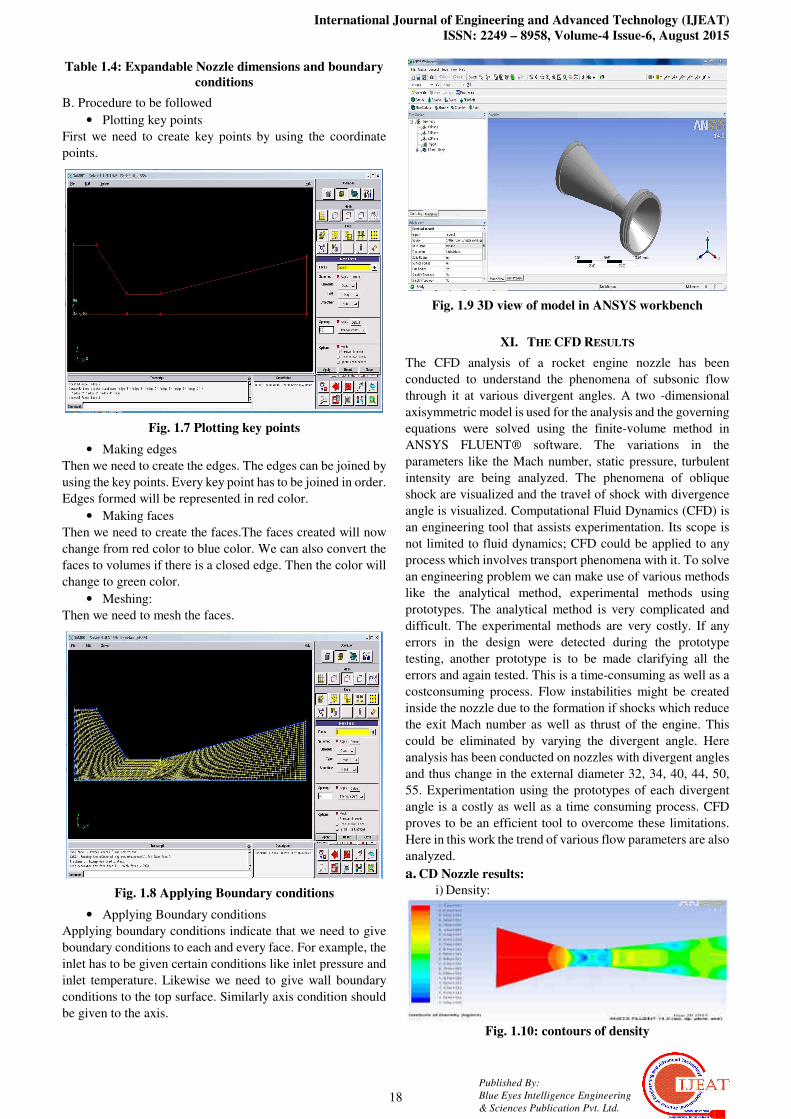
Table 1.4: Expandable Nozzle dimensions and boundary
conditions
B. Procedure to be followed
• Plotting key points
First we need to create key points by using the coordinate
points.
Fig. 1.7 Plotting key points
• Making edges
Then we need to create the edges. The edges can be joined by
using the key points. Every key point has to be joined in order.
Edges formed will be represented in red color.
• Making faces
Then we need to create the faces.The faces created will now
change from red color to blue color. We can also convert the
faces to volumes if there is a closed edge. Then the color will
change to green color.
• Meshing:
Then we need to mesh the faces.
Fig. 1.8 Applying Boundary conditions
• Applying Boundary conditions
Applying boundary conditions indicate that we need to give
boundary conditions to each and every face. For example, the
inlet has to be given certain conditions like inlet pressure and
inlet temperature. Likewise we need to give wall boundary
conditions to the top surface. Similarly axis condition should
be given to the axis.
Fig. 1.9 3D view of model in ANSYS workbench
XI. THE CFD RESULTS
The CFD analysis of a rocket engine nozzle has been
conducted to understand the phenomena of subsonic flow
through it at various divergent angles. A two -dimensional
axisymmetric model is used for the analysis and the governing
equations were solved using the finite-volume method in
ANSYS FLUENT® software. The variations in the
parameters like the Mach number, static pressure, turbulent
intensity are being analyzed. The phenomena of oblique
shock are visualized and the travel of shock with divergence
angle is visualized. Computational Fluid Dynamics (CFD) is
an engineering tool that assists experimentation. Its scope is
not limited to fluid dynamics; CFD could be applied to any
process which involves transport phenomena with it. To solve
an engineering problem we can make use of various methods
like the analytical method, experimental methods using
prototypes. The analytical method is very complicated and
difficult. The experimental methods are very costly. If any
errors in the design were detected during the prototype
testing, another prototype is to be made clarifying all the
errors and again tested. This is a time-consuming as well as a
costconsuming process. Flow instabilities might be created
inside the nozzle due to the formation if shocks which reduce
the exit Mach number as well as thrust of the engine. This
could be eliminated by varying the divergent angle. Here
analysis has been conducted on nozzles with divergent angles
and thus change in the external diameter 32, 34, 40, 44, 50,
55. Experimentation using the prototypes of each divergent
angle is a costly as well as a time consuming process. CFD
proves to be an efficient tool to overcome these limitations.
Here in this work the trend of various flow parameters are also
analyzed.
a. CD Nozzle results:
i) Density:
Fig. 1.10: contours of density

CFD Analysis on a Different Advanced Rocket Nozzles
19
Published By:
Blue Eyes Intelligence Engineering
& Sciences Publication Pvt. Ltd.
ii) Axial velocity
Fig. 1.11: contours of axial velocity
iii) Mach number
Fig. 1.12: contours of mach number
iv) Mach vector
Fig. 1.13: velocity vectors colored by mach number
v) Pressure
Fig. 1.14: contours of static pressure
vi) Radial velocity
Fig. 1.15: contours of radial velocity
vii) Velocity
Fig. 1.16 contours of velocity magnitude
viii) Velocity vector
Fig. 1.17: velocity vectors
ix) Velocity Magnitude
Fig. 1.18: velocity vectors contoured by velocity
magnitude
x) Vorticity Magnitude
Fig. 1.19: contours of vorticity magnitude
b) Bell Nozzle results:
i) Density
Fig. 1.20: contours of density
ii) Mach number
Fig. 1.21: contours of mach number
iii) Pressure
Fig. 1.22: contours of static pressure
iv) Velocity
Fig. 1.23: contours of velocity magnitude

International Journal of Engineering and Advanced Technology (IJEAT)
ISSN: 2249 – 8958, Volume-4 Issue-6, August 2015
20
Published By:
Blue Eyes Intelligence Engineering
& Sciences Publication Pvt. Ltd.
v) Radial velocity
Fig. 1.24: contours of radial velocity
vi) Temperature
Fig. 1.25: contours of static temperature
c) Dual Bell Nozzle:
i) Pressure
Fig. 1.26: contours of static pressure
ii) Density
Fig. 1.27: contours of density
iii) Velocity
Fig. 1.28: contours of velocity magnitude
iv) Temperature
Fig. 1.29: contours of static temperature
v) Turbulence
Fig. 1.30: contours of Turbulent Kinetic energy
d) Expandable Nozzle
i) Pressure
Fig. 1.31: contours of static pressure
ii) Density
Fig. 1.32: contours of density
iii) Velocity Vectors
Fig. 1.33: velocity vector
iv)Temperature
Fig. 1.34: contours of static temperature
v) Turbulent viscosity
Fig. 1.35: contours of turbulent viscosity
vi) Turbulent Kinetic Energy
Fig. 1.36 contours of Turbulent Kinetic Energy
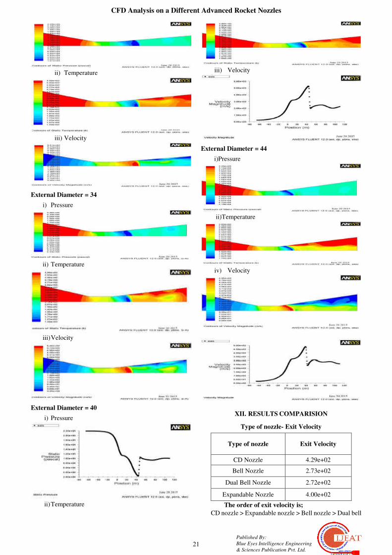
e) CD Nozzle experimentation with 32, 34, 40, 44 as
External Diameters
External Diameter = 32
i) Pressure
CFD Analysis on a Different Advanced Rocket Nozzles
21
Published By:
Blue Eyes Intelligence Engineering
& Sciences Publication Pvt. Ltd.
ii) Temperature
iii) Velocity
External Diameter = 34
i) Pressure
ii) Temperature
iii) Velocity
External Diameter = 40
i) Pressure
ii) Temperature
iii) Velocity
External Diameter = 44
i)Pressure
ii)Temperature
iv) Velocity
XII. RESULTS COMPARISION
Type of nozzle- Exit Velocity
Type of nozzle Exit Velocity
CD Nozzle 4.29e+02
Bell Nozzle 2.73e+02
Dual Bell Nozzle 2.72e+02
Expandable Nozzle 4.00e+02
The order of exit velocity is;
CD nozzle > Expandable nozzle > Bell nozzle > Dual bell

International Journal of Engineering and Advanced Technology (IJEAT)
ISSN: 2249 – 8958, Volume-4 Issue-6, August 2015
22
Published By:
Blue Eyes Intelligence Engineering
& Sciences Publication Pvt. Ltd.
XIII. CONCLUSION
Because of greater value for exit velocity, we can conclude
that convergent divergent nozzle can show better
performance than bell nozzle, dual bell nozzle and
expandable nozzles. Although benefits in performance were
indicated in most of the available publications, not many of
these nozzle concepts has yet been used in existing rocket
launchers. It is shown that significant performance gains
results from the adaptation of the exhaust flow to the ambient
pressure. All of the advanced nozzle concepts have been to
the subject of analytical work and gave much satisfactory
results, but Convergent divergent nozzle stands as best among
the nozzles we analyzed.
REFERENCES
Books: [1] Elements of propulsion – Mattingly
[2] Rocket propulsion elements – Sutton
[3] www.wikipedia.com/propelling_nozzle
[4] www.wikipedia.com/fluid_mechanics
[5] www.aerospaceweb.org