internally excited acoustic resonator for photoacoustic trace detection
TRANSCRIPT
Internally excited acoustic resonatorfor photoacoustic trace detection
Sorasak Danworaphong, Irio G. Calasso, Andrew Beveridge, Gerald J. Diebold,Claire Gmachl, Federico Capasso, Deborah L. Sivco, and A. Y. Cho
The quantum-cascade laser can be used as an infrared source for a small portable photoacoustic trace gasdetector. The device that we describe uses a quantum-cascade laser without collimating optics mountedinside an acoustic resonator. The laser is positioned in the center of a longitudinal resonator at apressure antinode and emits radiation along the length of the resonator exciting an axially symmetriclongitudinal acoustic mode of an open-ended cylindrical resonator. Experiments are reported with an8-�m, quasi-cw-modulated, room-temperature laser used to detect N2O. © 2003 Optical Society ofAmerica
OCIS code: 300.6430.
1. Introduction
Perhaps the most successful application of the pho-toacoustic effect1–5 has been for trace detection ofgases. The detection limit of a photoacoustic detec-tor consisting of an acoustic resonator, a microphone,an amplitude-modulated continuous laser, and alock-in amplifier is typically in the parts per billionrange; at the same time, the dynamic range of theinstrument can easily be over one million. The se-lectivity of the photoacoustic effect, where a narrow-band laser excites only those species with absorptionsat the laser wavelength, is also a valuable feature ofthe photoacoustic effect in its application to tracedetection. Since the first reports6–8 of use of CO andCO2 lasers to generate the photoacoustic effect ingases, high-power, continuous lasers have been theradiation source of choice for the production of thephotoacoustic effect in the infrared. Such lasers typ-ically produce a collimated beam of radiation with anoutput of the order of 1 W, which can be directed intoa cylindrical acoustic cell and modulated at the res-
S. Danworaphong is with the Department of Physics, BrownUniversity, Providence, Rhode Island 02912. I. G. Calasso, A.Beveridge, and G. J. Diebold �[email protected]� are withthe Department of Chemistry, Brown University, Providence,Rhode Island 02912. C. Gmachl, F. Capasso, D. L. Sivco, andA. Y. Cho are with Lucent Technologies, Bell Laboratories, 600Mountain Avenue, Murray Hill, New Jersey 07974.
Received 23 October 2002; revised manuscript received 18 July2003.
0003-6935�03�425561-05$15.00�0© 2003 Optical Society of America
2
onance frequency of an acoustic mode of the cell, in-creasing the amplitude of the photoacoustic effect byan amount proportional to the quality factor of theresonator and greatly enhancing the capability of thedevice for trace detection.
In practice, the magnitude of the photoacoustic ef-fect in gases is so large that in typical devices theoverall detection limit is limited not by the noise ofthe microphone but by a small extraneous acousticsignal, referred to as the “window” signal, generatedby absorption of radiation at the entrance and exitwindows of the cell.6,8,9 Over the years, a number ofresonator designs have been employed to reduce themagnitude of the window signal through use of baf-fles to block the acoustic signal generated at the win-dow from reaching the microphone or through designof the acoustic resonator so that the points of en-trance and exit of the laser beam in the cell are atacoustic nodes of the resonator, thereby nullifying thecontribution of the window signal to the mode of theresonator excited by the optical excitation. A reviewof the various resonator designs used to optimize de-tection limits has been given by Sigrist in Ref. 10.Generally speaking, it can be said that, even beforethe invention of the laser, the design of photoacousticresonators has been dictated to a large extent by thecharacteristics of the radiation source.
The quantum-cascade laser11,12 has been shown tobe admirably suited to gas phase absorbance mea-surements and trace detection in the nearinfrared.13–17 Photoacoustic trace detection hasbeen reported with a cryogenically cooled quantum-cascade laser18 in a device where the output of the
0 September 2003 � Vol. 27, No. 42 � APPLIED OPTICS 5561
laser was collimated and directed into a photoacous-tic resonator. Cryogenic cooling boosts the outputpower of the laser, but detracts substantially from thefield portability of a photoacoustic trace detector.Here we describe use of a quantum-cascade laser forphotoacoustic trace detection. The resonator designincorporates a laser placed inside the acoustic reso-nator and uses the radiation emitted from both endsof the laser chip to excite a longitudinal acoustic res-onance in an open tube. The laser beam, as a resultof its inherently large beam divergence, undergoesmultiple reflections off of the internal surfaces of theacoustic cavity filling the volume of the resonator.Unlike conventional photoacoustic resonator designswhere absorption of the laser beam at the windowsurfaces determines the detection limits, absorptionof the laser beam on reflection from the internal sur-faces of the resonator is sufficiently small that it doesnot provide the dominant source of noise; rather, it isthe intrinsic noise of the microphone that governs thetheoretical detection limit at the power levels of thelaser used here. Experimental results for operationof the device as an atmospheric pressure trace detec-tor of N2O at 8 �m are reported.
2. Experiments
The theory of photoacoustic excitation of an open-ended cylindrical resonator has been given by severalauthors.19–23 The pressure response of the resona-
tor is obtained through solution of the wave equationfor pressure, which follows from the coupled equa-tions for temperature and pressure in the limit ofnegligible heat conduction. The properties of a cy-lindrically symmetric, longitudinal resonator havebeen given in Refs. 24 and 25. The magnitude of thephotoacoustic pressure p for a longitudinal resonatordriven at its resonance frequency f, according to Ref.24, is given by
p � �lWLQ�� � 1�
2�fV, (1)
where � and � are the optical absorption coefficientand heat capacity ratio for the gas, respectively; WL isthe laser power; V and l are the volume and length ofthe cell, respectively; and Q is the quality factor of theresonance. An analysis of the dissipative factors ofthe cell show that the quality factor increases withthe radius of the resonator r, so the acoustic pressurescales as the inverse of the radius.
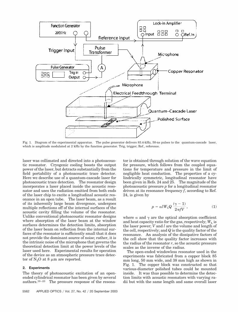
The open-ended windowless resonator used in theexperiments was fabricated from a copper block 85mm long, 50 mm wide, and 38 mm high as shown inFig. 1. The copper block was constructed so thatvarious-diameter polished tubes could be mountedinside. It was thus possible to determine the detec-tion limits with acoustic resonators with varying ra-dii but with the same length and same overall laser
Fig. 1. Diagram of the experimental apparatus. The pulse generator delivers 83.4-kHz, 50-ns pulses to the quantum-cascade laser,which is amplitude modulated at 2 kHz by the function generator. Trig, trigger; Ref., reference.
5562 APPLIED OPTICS � Vol. 27, No. 42 � 20 September 2003
power. A Bruel and Kjaer 0.50-in. ��1.27-cm� con-denser microphone, Model 4130, was placed at thecenter of the resonator directly above the quantum-cascade laser at a pressure antinode of the resonator.The channel for the microphone leading into the in-terior of the resonator was approximately the samediameter as the microphone diaphragm. Thequantum-cascade laser chip was attached to a copperplate, which, in turn, was mounted on an interiorsurface of the cell located at the center of the resona-tor. The laser was fabricated to emit radiation attwo surfaces on opposite ends of the chip so thatradiation filled the resonator in both directions fromthe center of the resonator. The laser, which waselevated a few millimeters above the bottom of theresonator channel, was positioned at the center of theresonator with the copper block forming one electrodeand an insulated pin fed through the upper copperblock forming the second. The resonator design,with both the laser and the microphone located at avelocity node, which is a pressure antinode of theresonator, as well, is perhaps an optimum placementfor these two components, providing only a small per-turbation of the longitudinal resonance. The con-struction of the cell was such that heat generated bythe laser, operated without an external coolingsource, was dissipated by conduction to the base ofthe cell. A Hewlett-Packard Model 8114A pulsegenerator whose output was fed to an Avtech, Inc.Model AVX-M3 pulse transformer drove the quan-tum cascade at 83.4 kHz with 50-ns square pulses.The output of the pulse generator, in turn, wassquare-wave modulated at the resonance frequencyof the acoustic cavity, 2 kHz, by an external functiongenerator. The maximum voltage and current atthe pulser output before the step-down transformerwas 50 V and 1.5 A, respectively. The signal fromthe microphone was fed without further amplificationto a two-channel lock-in amplifier.
The laser operated at 1248 cm�1 with a bandwidthof 1 cm�1 at room temperature. We determined thelaser power by first calibrating a Fermionics, Inc.Model PV-12-1-T liquid-nitrogen-cooled HgCdTe de-tector. A 1-W CO2 laser beam was directed througha ZnSe lens and pinhole, and its power was measuredwith a conventional thermopile laser powermeter at apoint where the expanded beam filled the face of thedetector. The beam profile of the expanded laserbeam beyond the focal point of the lens was thendetermined by use of a liquid-crystal sheet. Next,the HgCdTe detector was placed in the expandedlaser beam together with calibrated attenuators, andits output voltage was recorded. With these mea-surements it was possible to calibrate the intensityresponse of the HgCdTe detector �volts per watt� atan intensity low enough so as not to exceed the linearrange of the detector. The beam profile of thequantum-cascade laser was determined by scanningthe laser across the face of the HgCdTe detector.The quantum-cascade laser output power was deter-mined from a knowledge of its beam profile and thesignal from the HgCdTe detector, corrected for its
spectral response. The quantum-cascade laser wasfound to emit a time-averaged total power of 10 �Won each face.
The detection limit of the resonator was deter-mined with N2O at 1 atm. The absorption coeffi-cient of N2O at 1 atm was determined by placing a10-cm-long absorption cell equipped with NaCl win-dows between the quantum-cascade laser and theHgCdTe detector. The transmission of the cell wasrecorded with a series of gas mixtures of N2O dilutedin Ar at mole fractions from 0.2 to 1. The figureobtained for the extinction coefficient, 0.17 cm�1 at 1atm, corresponds to the absorption of the gas withoutconsideration of linewidth, the mode structure, or theexact wavelength of the laser relative to the absorp-tion maximum of the N2O; although the extinctioncoefficient is not transferable to other infraredsources, it provides an integrated absorption coeffi-cient characteristic of the spectral emission profile ofthe laser used here and permits determination of aphotoacoustic detection limit.
The measurements were performed in neat N2O byfilling the resonator in an acoustically isolated con-tainer by recording the signal from the lock-in am-plifier at the frequency where the signal amplitudewas at its maximum. The sound speed in N2O is 263m�s, which is somewhat lower than that in air, so themodulation frequency of the laser was adjusted cor-respondingly downward so that the resonator wasoperated on resonance. With the resonator filledwith Ar, a plot of the microphone signal from thelock-in amplifier versus the driving voltage on thequantum-cascade laser showed a gradual increase insignal with increasing drive voltage from the pulsegenerator even before the lasing threshold wasreached, indicating that the background signal in thecell was electrical and did not arise from absorption oflaser radiation at the resonator walls; hence, it fol-lows that the equivalent of the window signal in aconventional photoacoustic detector, which is absorp-tion of the laser radiation at the walls of the cell in thepresent experiments, cannot be considered the pri-mary factor in the determination of the detectionlimit. With the laser operating above threshold, theelectrical pickup seen in the lock-in amplifier was 3.5mV. No efforts were made to reduce the electricalpickup, although minor modification of the electricalfeedthrough from the pulse generator or a modifica-tion of the shielding of the microphone would be ex-pected to reduce the electromagnetic couplingbetween the pulse generator and the microphone.Electrical pickup can be reduced by proper design ofthe electrical feedthroughs into the quantum-cascadelaser and is not considered a fundamental limitationon the detection limit of the device. The intrinsicnoise of the microphone and electronics, insofar asthis study is concerned, constitutes a source of noisethat cannot be eliminated and hence determines thetheoretical limit for photoacoustic detection.26 Theinternal noise in the microphone was determinedthrough a turning off of the pulse generator and re-cording the noise in the microphone in an acoustical
20 September 2003 � Vol. 27, No. 42 � APPLIED OPTICS 5563
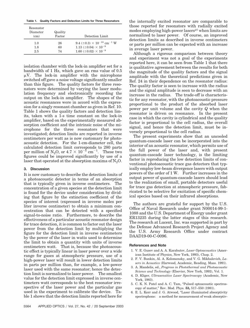
isolation chamber with the lock-in amplifier set for abandwidth of 1 Hz, which gave an rms value of 0.5�V. The lock-in amplifier with the microphoneswitched off gave a noise voltage significantly smallerthan this figure. The quality factors for three reso-nators were determined by varying the laser modu-lation frequency and electronically recording theoutput on the lock-in amplifier. The shapes of theacoustic resonances were in accord with the expres-sion for a singly resonant chamber as given in Ref. 10.Table 1 shows the quality factors and detection lim-its, taken with a 1-s time constant on the lock-inamplifier, based on the experimentally measured ab-sorption coefficient and the intrinsic noise of the mi-crophone for the three resonators that wereinvestigated; detection limits are reported in inversecentimeters per watt as is now customary for photo-acoustic detection. For the 1-cm-diameter cell, thecalculated detection limit corresponds to 280 partsper million of N2O, or 4.7 � 10�5 cm�1. These twofigures could be improved significantly by use of alaser that operated at the absorption maxima of N2O.
3. Discussion
It is now customary to describe the detection limits ofa photoacoustic detector in terms of an absorptionthat is typically given in inverse centimeters. Theconcentration of a given species at the detection limitis found for the device under consideration by divid-ing that figure by the extinction coefficient of thespecies of interest �expressed in inverse moles perliter inverse centimeter� to obtain a minimum con-centration that can be detected with a specifiedsignal-to-noise ratio. Furthermore, to describe theeffectiveness of a particular acoustic resonator designfor trace detection, it is common to factor out the laserpower from the detection limit by multiplying thefigure for the detection limit in inverse centimetersby the power of the laser in watts used to determinethe limit to obtain a quantity with units of inversecentimeters watt. That is, because the photoacous-tic effect is typically linear in laser power over a widerange for gases at atmospheric pressure, use of ahigh-power laser will result in lower detection limitsin parts per million than, for example, a low-powerlaser used with the same resonator; hence the detec-tion limit is normalized to laser power. The smallestvalue for the detection limit expressed in inverse cen-timeters watt corresponds to the best resonator irre-spective of the laser power and the particular gasused in the experiment to calibrate the device. Ta-ble 1 shows that the detection limits reported here for
the internally excited resonator are comparable tothose reported for resonators with radially excitedmodes employing high-power lasers27 when limits arenormalized to laser power. Of course, an improveddetection limits as described in inverse centimetersor parts per million can be expected with an increasein average laser power.
Although a rigorous comparison between theoryand experiment was not a goal of the experimentsreported here, it can be seen from Table 1 that thereis qualitative agreement between the results for boththe magnitude of the quality factors and the signalamplitude with the theoretical predictions given inRef. 24 in their dependence on the resonator radius:The quality factor is seen to increase with the radiusand the signal amplitude is seen to decrease with anincrease in the radius. The trade-off is characteris-tic for any resonator, with the photoacoustic pressureproportional to the product of the absorbed laserpower per unit volume and the cavity Q when theresonator is driven on resonance. In the presentcase in which the cavity is cylindrical and the qualityfactor is proportional to the cell radius, the overallsignal, and hence the detection limit, must be in-versely proportional to the cell radius.
The present experiments show that an uncooledquantum-cascade laser can be incorporated into theinterior of an acoustic resonator, which permits use ofthe full power of the laser and, with presentquantum-cascade laser technology, is the limitingfactor in reproducing the low detection limits of con-ventional photoacoustic trace gas detectors that typ-ically employ low-beam divergence lasers with outputpowers of the order of 1 W. Further increases in theoutput power of quantum-cascade lasers should leadto the realization of small, portable detectors usefulfor trace gas detection at atmospheric pressure, fab-ricated to be selective for excitation of specific chem-ical species based on their infrared absorptions.
The authors are grateful for support by the U.S.Office of Naval Research under grant N00014-99-1-1088 and the U.S. Department of Energy under grantER13235 during the latter stages of this research.The research at Lucent, Inc. was supported in part bythe Defense Advanced Research Project Agency andthe U.S. Army Research Office under contractDAAD19-00-C-0096.
References and Note1. V. E. Gusev and A. A. Karabutov, Laser Optoacoustics �Amer-
ican Institute of Physics, New York, 1993�, Chap. 2.2. F. V. Bunkin, Al. A. Kolomensky, and V. G. Mikhalevich, La-
sers in Acoustics �Harwood, Academic, Reading, Mass. 1991�.3. A. Mandelis, ed., Progress in Photothermal and Photoacoustic
Science and Technology �Elsevier, New York, 1992�, Vol. 1.4. D. Kliger, Ultrasensitive Laser Spectroscopy �Academic, New
York, 1983�.5. C. K. N. Patel and A. C. Tam, “Pulsed optoacoustic spectros-
copy of matter,” Rev. Mod. Phys. 53, 517–550 �1981�.6. E. L. Kerr and J. G. Atwood, “Laser illuminated absorptivity
spectrophone: a method for measurement of weak absorptiv-
Table 1. Quality Factors and Detection Limits for Three Resonators
ResonatorDiameter
�cm�QualityFactor Detection Limit
1.0 26 9.4 �0.3� � 10�10 cm�1 W1.8 60 1.13 �0.04� � 10�9
2.5 74 1.60 �0.02� � 10�9
5564 APPLIED OPTICS � Vol. 27, No. 42 � 20 September 2003
ity in gases at laser wavelengths,” Appl. Opt. 7, 915–918.�1968�.
7. L. B. Kreuzer, “Ultralow gas concentration infrared absorptionspectroscopy,” J. Appl. Phys. 42, 2934–2943 �1971�.
8. L. B. Kreuzer, N. D. Kenyon, and C. K. N. Patel, “Air pollution:sensitive detection of ten pollutant gases by carbon monoxideand carbon dioxide lasers,” Science 177, 347–349 �1972�.
9. J. G. Choi and G. J. Diebold, “A Helmholtz resonator opto-acoustic detector for gas chromatography,” Anal. Chem. 59,519–521 �1987�.
10. M. W. Sigrist, ed., Air Monitoring by Spectroscopic Techniques,Vol. 127 of Chemical Analysis Series �Wiley, New York, 1994�,p. 163.
11. C. Gmachl, F. Capasso, D. L. Sivco, and A. Y. Cho, “Recentprogress in quantum cascade lasers and applications,” Rep.Prog. Phys. 64, 1533–1601 �2001�.
12. F. Capasso, C. Gmachl, D. L. Sivco, and A. Y. Cho, “Quantumcascade lasers,” Phys. Today 55, 34–40 �2002�.
13. A. A. Kosterev, R. F. Curl, and F. K. Tittel, “Methane concen-tration and isotopic composition measurements with a mid-infrared quantum-cascade laser,” Opt. Lett. 24, 1762–1764�1999�.
14. J. T. Remillard, D. Uy, W. H. Weber, F. Capasso, C. Gmachl,A. L. Hutchinson, D. L. Sivco, J. N. Ballargeon, and A. Y. Cho,“Sub-Doppler resolution limited Lamb-dip spectroscopy of NOwith a quantum cascade distributed feedback laser,” Opt. Exp.7, 243–248 �2000�, http:��www.opticsexpress.org.
15. B. A. Paldus, C. C. Harb, T. G. Spence, R. N. Zare, C. Gmachl,F. Capasso, D. L. Sivco, J. N. Baillargeon, A. L. Hutchinson,and A. Y. Cho, “Cavity ringdown spectroscopy using mid-infrared quantum-cascade lasers,” Opt. Lett. 25, 666–668�2000�.
16. C. M. Gittins, E. T. Wetjen, C. Gmachl, F. Capasso, A. L.Hutchinson, D. L. Sivco, J. N. Baillargeon, and A. Y. Cho,“Quantitative gas sensing by backscatter-absorption measure-ments of a pseudorandom code modulated quantum cascadelaser,” Opt. Lett. 25, 1162–1164 �2000�.
17. A. A. Kosterev, A. L. Malinovsky, F. K. Tittel, C. Gmachl, F.Capasso, D. L. Sivco, J. N. Baillargeon, A. L. Hutchinson, and
A. Y. Cho, “Cavity ringdown spectroscopic detection of nitricoxide with a continuous-wave quantum-cascade laser,” Appl.Opt. 40, 5522–5529 �2001�.
18. B. A. Paldus, T. G. Spence, R. N. Zare, J. Oomens, F. J. M.Harren, D. H. Parker, C. Gmachl, F. Cappasso, D. L. Sivco,N. J. Baillargeon, A. L. Hutchinson, and A. Y. Cho, “Photo-acoustic spectroscopy using quantum-cascade lasers,” Opt.Lett. 24, 178–180 �1999�.
19. A. Karbach and P. Hess, “High precision acoustic spectroscopyby laser excitation of resonator modes,” J. Chem. Phys. 83,1075–1084 �1985�.
20. A. Karbach and P. Hess, “Photoacoustic signal in a cylindricalresonator: theory and laser experiments for CH4 and C2H6,”J. Chem. Phys. 84, 2945–2952 �1985�.
21. G. Busse and D. Herboeck, “Differential Helmholtz resonatoras an optoacoustic detector,” Appl. Opt. 18, 3959–3961 �1979�.
22. J. Pelzl, K. Klein, and O. Nordaus, “Extended Helmholtz res-onator in low-temperature photoacoustic spectroscopy,” Appl.Opt. 21, 94–99 �1982�.
23. A. Miklos and A. Lorinez, “Windowless resonant acousticchamber for laser-photoacoustic applications,” Appl. Phys. B48, 213–218 �1989�.
24. S. Bernegger and M. W. Sigrist, “Longitudinal resonant spec-trophone for CO laser photoacoustic spectroscopy,” Appl. Phys.B 44, 125–132 �1987�.
25. F. G. C. Bijnen, J. Reuss, and F. H. M. Harren, “Geometricaloptimization of a longitudinal resonant photoacoustic cell forsensitive and fast trace gas detection,” Rev. Sci. Instrum. 67,2914–2923 �1996�.
26. The limiting theoretical sensitivity of a microphone is deter-mined by thermal fluctuations in the position of the mem-brane. In practice, the noise introduced by the first amplifierstage is often greater than the thermal noise in the membraneposition. For the purposes of this experiment, the noise mea-sured in the microphone is taken to determine the detectionlimit, irrespective of whether the microphone achieves thethermal noise limit.
27. V. P. Zharov and V. S. Letokhov, Laser Optoacoustic Spectros-copy �Springer-Verlag, New York, 1986�, see Table 5.3.
20 September 2003 � Vol. 27, No. 42 � APPLIED OPTICS 5565