intermec ethernet adapterapps.intermec.com/downloads/eps_man/068749.pdf · chapter 4 explains how...
TRANSCRIPT
Intermec Ethernet Adapter
P/N 068749-003
User’s Manual

Intermec Technologies Corporation6001 36th Avenue WestP.O. Box 4280Everett, WA 98203-9280
U.S. service and technical support: 1.800.755.5505U.S. media supplies ordering information: 1.800.227.9947
Canadian service and technical support: 1.800.688.7043Canadian media supplies ordering information: 1.800.268.6936
Outside U.S. and Canada: Contact your local Intermec service supplier.
The information contained herein is proprietary and is provided solely for the purpose of allowing customersto operate and/or service Intermec manufactured equipment and is not to be released, reproduced, or used forany other purpose without written permission of Intermec.
Information and specifications in this manual are subject to change without notice.
1998-1999 by Intermec Technologies CorporationAll Rights Reserved
The word Intermec, the Intermec logo, JANUS, IRL, TRAKKER, Antares, Adara, Duratherm, EZBuilder,EasyCoder, Precision Print, PrintSet, Virtual Wedge, and CrossBar are either trademarks or registeredtrademarks of Intermec.
AIX, Apple, DEC, DOS, Ethernet, EtherTalk, HP, IBM, JetAdmin, Internet Explorer, LAN Manager, LANServer, LANtastic, Macintosh, Microsoft, MVS, NDPS, Netscape, Novell NetWare, OS/2, OS/400, PostScript,SCO, UNIX, VM, VMS, VSE, Windows, AXIS NetPilot, and AXIS ThinServer are registered trademarks ofthe respective holders.
Throughout this manual, trademarked names may be used. Rather than put a trademark ( or ) symbol inevery occurrence of a trademarked name, we state that we are using the names only in an editorial fashion, andto the benefit of the trademark owner, with no intention of infringement.
iii
Manual Change RecordThis page records the changes to this manual. The manual was originally released as version 001.
Version Date Description of Change
002 2/99 Added information on the internal Ethernet adapter Part No. 069227 and aprocedure for printing a test label in Data Line Print mode.
003 3/99 Added information to configuring using AXIS NetPilot.


Contents
v
ContentsBefore You Begin xi
Warranty Information xiSafety Summary xiWarnings, Cautions, and Notes xiiAbout This Manual xii
Introducing the Ethernet AdapterOverview 1-3
Physical Description 1-4Computer Environments 1-5Installing and Integrating 1-6Configuring and Managing 1-6
Features and Benefits 1-6
Using the Test Button 1-7
Connecting the Ethernet AdapterConnecting the Ethernet Adapter to Your Network 2-3
Guide to Installing the Ethernet Adapter on Your Network 2-3Installation Summary 2-4
Setting Up With AXIS NetPilot 2-5Installing AXIS Print Utilities 2-5Using AXIS NetPilot 2-5
Setting Up for TCP/IP 2-7Downloading the IP Address 2-8
Using DHCP in Windows 2-9Using ARP in Windows 95, 98, or NT 2-9Using ARP in UNIX 2-10Using RARP in UNIX 2-10Using BOOTP in UNIX 2-11
Assigning a Host Name to the IP Address 2-12Installing the LPR Spooler 2-12
Configuring the Centronics Interface Timing 2-13
Printing a Test Label 2-13
1
2
Intermec Ethernet Adapter User’s Manual
vi
Setting Up the Ethernet Adapter for a NetWareNetworkSetting Up Your Ethernet Adapter Using NDPS 3-3
Printing Methods 3-4Print Server Mode 3-4Remote Printer Mode 3-4
Advanced Installation Using AXIS NetPilot 3-4
Setting Up the Ethernet Adapter for a WindowsNetworkUsing the AXIS Print Monitor for Windows 95, 98, and NT 4-3
About the AXIS Print Monitor 4-3Printing Environments 4-3Peer-to-Peer Printing 4-3Client/Server Printing 4-4User Dialog 4-4
Using the AXIS Print Monitor With Windows 95 or 98 4-4Using the AXIS Print Monitor With Windows NT 4.0 4-6Using the AXIS Print Monitor With Windows NT 3.5X 4-8
Using the Microsoft LPD Monitor for Windows NT 4-9Using the Microsoft LPD Monitor With Windows NT 4.0 4-10Using the Microsoft LPD Monitor With Windows NT 3.5X 4-11
Setting Up the Ethernet Adapter to Use an LPR Spooler 4-12
Using the AXIS Print Utility for Windows 4-12About AXIS Print Utility for Windows 4-13Peer-to-Peer vs. Client/Server Printing 4-13
Windows Clients Using LANtastic 4-16
3
4

Contents
vii
Setting Up the Ethernet Adapter for an OS/2 NetworkUsing the AXIS Print Utility for OS/2 5-3
Integrating Your Ethernet Adapter Into the OS/2 Environment 5-4Creating a Print Queue 5-4Sharing the Print Queue 5-4
Setting Up the Ethernet Adapter for a MacintoshNetworkInstalling Using the Chooser Window 6-3
Communications Support and Protocols 6-3
Setting Parameters 6-3
Setting Up the Ethernet Adapter for a UNIX NetworkIntegrating Into the Host Printer Spooler 7-3
Print Methods on TCP/IP Networks 7-4Line Printer Daemon 7-5File Transfer Protocol 7-5PROS 7-5
PROS A 7-6PROS B 7-6
Reverse Telnet 7-6Other Systems 7-6
Other UNIX Systems 7-6IBM MVS Systems 7-6
Customizing Your Printing 7-7Converting Character Sets 7-7Adding Strings Before and After Print Jobs 7-8Substituting Strings 7-8Converting ASCII to PostScript 7-9Reading Back Information 7-10Debugging Using the Hex Dump Mode 7-10
5
6
7

Intermec Ethernet Adapter User’s Manual
viii
Managing and Configuring the Ethernet AdapterIntroduction 8-3
Using a Web Browser to Manage and Configure the Ethernet Adapter 8-4
Using AXIS NetPilot to Manage and Configure the Ethernet Adapter 8-6Starting AXIS NetPilot 8-7Changing the Parameter Values 8-7
Property Pages 8-7Parameter List Editor 8-8
Modifying the Network Environments 8-9Monitoring Printers 8-9Grouping Logically Connected Adapters 8-10Finding Printer Information 8-10
Using FTP to Manage and Configure the Ethernet Adapter 8-12Editing the Configuration File 8-12Viewing the Status File 8-13Viewing the Account File 8-13
Using Telnet to Manage and Configure the Ethernet Adapter 8-14Viewing the Accounting File 8-14Viewing the Status File 8-15Performing Resets 8-15
Using SNMP to Manage and Configure the Ethernet Adapter 8-16System Requirements for SNMP 8-16About AXIS MIB 8-16
Using HP Administration Tools to Manage and Configure the Ethernet Adapter 8-17
Using Other NetWare Configuration Methods 8-17Printer Status 8-17Notification 8-18Print Layout 8-18
Updating the SoftwareObtaining Updated Software 9-3
Downloading the Software Over the Internet 9-3Downloading the Software Over Anonymous FTP 9-3
8
9

Contents
ix
Updating the Flash Memory 9-3Updating Using the AXIS NetPilot 9-4Upgrading Over the Network Using FTP 9-4
Configuration ParametersChanging the Configuration Parameters A-3
Using AXIS NetPilot A-3Using a Web Browser A-3Using FTP A-3
Using FTP for UNIX, Windows, and OS/2 Workstations A-3Using FTP for Macintosh A-4
Sample Configuration Parameters A-4
Technical SpecificationsSoftware Specifications B-3
Physical Specifications B-4
Index
A
B
I


Before You Begin
xi
Before You BeginThis section introduces you to standard warranty provisions, safety precautions,warnings and cautions, document formatting conventions, and sources of additionalproduct information. A documentation roadmap is also provided to guide you in findingthe appropriate information.
Warranty InformationTo receive a copy of the standard warranty provision for this product, contact your localIntermec support services organization. In the U.S. call 1.800.755.5505, and in Canadacall 1.800.688.7043. Otherwise, refer to the Worldwide Sales & Service list that shipswith this manual for the address and telephone number of your Intermec salesorganization.
Safety SummaryYour safety is extremely important. Read and follow all warnings and cautions in thisbook before handling and operating Intermec equipment. You can be seriously injured,and equipment and data can be damaged if you do not follow the safety warnings andcautions.
Do not repair or adjust alone Do not repair or adjust energized equipment aloneunder any circumstances. Someone capable of providing first aid must always bepresent for your safety.
First aid Always obtain first aid or medical attention immediately after an injury.Never neglect an injury, no matter how slight it seems.
Resuscitation Begin resuscitation immediately if someone is injured and stopsbreathing. Any delay could result in death. To work on or near high voltage, you shouldbe familiar with approved industrial first aid methods.
Energized equipment Never work on energized equipment unless authorized by aresponsible authority. Energized electrical equipment is dangerous. Electrical shockfrom energized equipment can cause death. If you must perform authorized emergencywork on energized equipment, be sure that you comply strictly with approved safetyregulations.

Intermec Ethernet Adapter User’s Manual
xii
Warnings, Cautions, and NotesThe warnings, cautions, and notes in this manual use the following format.
WarningA warning alerts you of an operating procedure, practice, condition, or statementthat must be strictly observed to avoid death or serious injury to the personsworking on the equipment.
AvertissementUn avertissement vous avertit d’une procédure de fonctionnement, d’une méthode,d’un état ou d’un rapport qui doit être strictement respecté pour éviter l’occurrencede mort ou de blessures graves aux personnes manupulant l’équipement.
CautionA caution alerts you to an operating procedure, practice, condition, or statementthat must be strictly observed to prevent equipment damage or destruction, orcorruption or loss of data.
ConseilUne précaution vous avertit d’une procédure de fonctionnement, d’une méthode,d’un état ou d’un rapport qui doit être strictement respecté pour empêcherl’endommagement ou la destruction de l’équipement, ou l’altération ou la perte dedonnées.
Notes: Notes are statements that either provide extra information about a topic orcontain special instructions for handling a particular condition or set of circumstances.
About This ManualThis manual contains all of the information necessary to install, configure, and maintainthe Intermec Ethernet adapter.
This manual was written for analysts and system administrators who operate, program,and connect the Ethernet adapter to a network or system. A basic understanding of yournetwork, programming, and data communications is necessary.

Before You Begin
xiii
What You Will Find in This ManualThis table summarizes the information in each chapter of this manual:
Chapter Description
Chapter 1 Gives an overview of how to use the Ethernet adapter and lists features andbenefits.
Chapter 2 Explains how to attach the Ethernet adapter to your printer and network andset up your Ethernet adapter for TCP/IP protocol in different networkenvironments.
Chapter 3 Explains how to configure your Ethernet adapter in a NetWare network.
Chapter 4 Explains how to configure your Ethernet adapter in a Windows network.
Chapter 5 Explains how to configure your Ethernet adapter in an OS/2 network.
Chapter 6 Explains how to configure your Ethernet adapter in a Macintosh network.
Chapter 7 Explains how to configure your Ethernet adapter in a UNIX network.
Chapter 8 Describes how you can change the Ethernet adapter parameter values.
Chapter 9 Explains how to obtain and update the software on the Ethernet adapter.
Appendix A Explains how to change the parameter values and provides a sampleconfiguration file.
Appendix B Provides a list of the software and hardware specifications for the Ethernetadapter.
TerminologyYou should be aware of how these terms are being used in this manual:
Term Description
Ethernet adapter The generic term “Ethernet adapter” indicates both the externaland internal Ethernet adapter. More specific terms, such as“external Ethernet adapter,” indicate one or the other type ofEthernet adapter.
Environment “Environment” indicates the operating system of the network,such as Windows or Macintosh.
Printer “Printer” refers to any Intermec bar code label printer.
Intermec Ethernet Adapter User’s Manual
xiv
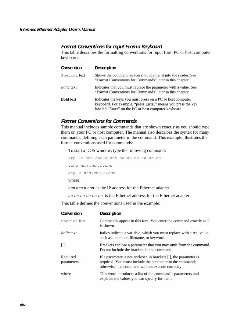
Format Conventions for Input From a KeyboardThis table describes the formatting conventions for input from PC or host computerkeyboards:
Convention Description
Special text Shows the command as you should enter it into the reader. See“Format Conventions for Commands” later in this chapter.
Italic text Indicates that you must replace the parameter with a value. See“Format Conventions for Commands” later in this chapter.
Bold text Indicates the keys you must press on a PC or host computerkeyboard. For example, “press Enter” means you press the keylabeled “Enter” on the PC or host computer keyboard.
Format Conventions for CommandsThis manual includes sample commands that are shown exactly as you should typethem on your PC or host computer. The manual also describes the syntax for manycommands, defining each parameter in the command. This example illustrates theformat conventions used for commands:
To start a DOS window, type the following command:
arp -s nnn.nnn.n.nnn nn-nn-nn-nn-nn-nn
ping nnn.nnn.n.nnn
arp -d nnn.nnn.n.nnn
where:
nnn.nnn.n.nnn is the IP address for the Ethernet adapter
nn-nn-nn-nn-nn-nn is the Ethernet address for the Ethernet adapter
This table defines the conventions used in the example:
Convention Description
Special font Commands appear in this font. You enter the command exactly as itis shown.
Italic text Italics indicate a variable, which you must replace with a real value,such as a number, filename, or keyword.
[ ] Brackets enclose a parameter that you may omit from the command.Do not include the brackets in the command.
Requiredparameters
If a parameter is not enclosed in brackets [ ], the parameter isrequired. You must include the parameter in the command;otherwise, the command will not execute correctly.
where This word introduces a list of the command’s parameters andexplains the values you can specify for them.

Before You Begin
xv
Other Intermec ManualsYou may need additional information when working with the Ethernet adapter in a datacollection system. Please visit our web site at www.intermec.com to access many of ourcurrent manuals in PDF format. To order printed versions of the Intermec manuals,contact your local Intermec representative or distributor.

Introducing the Ethernet Adapter
1

code39 code39 Introducing the Ethernet Adapter
1-3
1This chapter gives an overview of how and where to use your Ethernet adapter andexplains the features of your Ethernet adapter.
OverviewThe external Ethernet adapter, Part No. 068788, and the internal Ethernet adapters, PartNo. 068789 and 069227, allow you to share your available printer resources witheveryone on your Ethernet network.
You can connect only the external Ethernet adapter to the following Intermec printersto print labels:
• 91* printers • 601XP printers
• 301* printers • 901* printers
• 401* printers • 4630* printers
• 501*, 501E*, 501S*, and 501XP printers • 7421 and 7422* printers
* These printer models require an external power supply to run the external Ethernetadapter.
You can connect either the external or the internal Ethernet adapter Part No. 068789 tothe following Intermec printers to print labels:
• 3240* printers
• 3400* and 3440* printers
• 3600* printers
• 4400* printers
* These printer models require an external power supply to run the external Ethernetadapter.
Note: For the 3240, 3400, 3440, 3600, and 4400 printers, you must have the parallelport option installed on your printer to connect the external Ethernet adapter. TheEthernet adapter is not compatible with the 4400A, but you can use the adapter with alllater 4400 models.
You can connect the Ethernet adapter Part No. 069227 to the 4420 and 4440 printers.
Note: With the internal Ethernet adapter installed, the parallel port on the 4420 and4440 printers is not available for use.
The Ethernet adapter uses a twisted pair (10BaseT) connection with a network speed of10 Mbps. Throughout the manual, “Ethernet adapter” will be used to refer to both theinternal and external adapter unless specified.

Intermec Ethernet Adapter User’s Manual code39 code39
1-4
Physical DescriptionExternal Ethernet Adapter
10BaseTconnector
Externalpowersupplyconnector
PowerLED
Network LED
Parallel port connector
Test button
AXISI.001
+
Internal Ethernet Adapter
O
I
NetworkLED
PowerLED
Test button
10BaseTconnector
AXISI.002
code39 code39 Introducing the Ethernet Adapter
1-5
1Physical Description (continued)
Part Function
10BaseT connector Connects the Ethernet adapter to a 10 Mbps Ethernet network via a10BaseT cable.
Parallel port connector(external Ethernet adapteronly)
Provides the external Ethernet adapter with a single high-speedparallel port that can connect directly, without the need of cabling,to an Intermec printer with a parallel port installed.
Test button Use the Test button to:
• Print the print quality label to check the connection to theprinter. This functionality only works with firmware version5.59 or higher.
• Print the parameter list that shows some of the Ethernetadapter’s settings. This functionality only works with firmwareversion 5.59 or higher.
• Reset the Ethernet adapter’s parameters to the factory defaultsettings.
Refer to “Using the Test Button” later in this chapter for moreinformation about the Test button.
Network LED Flashes to indicate network activity.
Power LED Lights up while power is applied. If the power light emitting diode(LED) is off or flashes, there is a problem with the Ethernet adapteror its power supply.
Computer EnvironmentsThe Ethernet adapter is the ideal print server in mixed computer environments as it cancommunicate with all the major systems and network protocols including:
• NetWare
• UNIX
• Windows
• Windows clients connected to LANtastic networks
• OS/2
• Macintosh
• Internet/intranet via any standard Web browser
Intermec Ethernet Adapter User’s Manual code39 code39
1-6
Installing and IntegratingYou need the appropriate Axis client software, which comes with your adapter, toinstall and integrate the Ethernet adapter:
• AXIS NetPilot (NetWare)
• AXIS Print Monitor (Windows 95 or 98)
• AXIS Print Utility for Windows (Windows 3.1 and Windows for Workgroups)
• AXIS Print Utility for OS/2
• axinstall (UNIX)
The Ethernet adapter can be installed in the Macintosh environment without any Axissoftware.
Configuring and ManagingUsing the Ethernet adapter’s built-in Web server, you can configure and manage theEthernet adapter directly from its internal Web pages using hypertext transfer protocol(HTTP) over transmission control protocol/Internet protocol (TCP/IP). Using anystandard Web browser, you can manage your Ethernet adapter independent of yournetwork environment.
If your network does not support TCP/IP, you can use the AXIS NetPilot software toconfigure the Ethernet adapter in any other environment.
Features and BenefitsReliability The Ethernet adapter provides high performance and reliability combined with low
power consumption. The electronic circuits are based on the proven AXIS ETRAXchip that comprises an integrated 32 bit RISC processor and associated networkcontrollers.
Flexibility It supports printing in all the major computer systems and environments, including fivedifferent print methods in the TCP/IP environment.
Speed The AXIS ETRAX chip is designed for LAN products and gives you faster throughputthan a direct PC-to-printer connection. With a sustained data throughput of up to 390Kper second, the Ethernet adapter is fast. High speed Centronics communication such asHewlett-Packard Fast Mode, High Speed, and IBM Fast Byte is supported.
Easy to Install You can install the Ethernet adapter in minutes, using the AXIS NetPilot installationsoftware. Its Installation Wizard, together with the axinstall script for UNIXworkstations, allows installation into the Ethernet adapter’s networking environments.
Security You can assign passwords to restrict login and printer access.

code39 code39 Introducing the Ethernet Adapter
1-7
1Features and Benefits (continued)
Monitoring The provided AXIS NetPilot software and the Ethernet adapter’s internal Web pagesallow you to continuously monitor printer status.
The AXIS Print Monitor for Windows 95, 98, and NT can be configured to displaypop-up messages that show the status of peer-to-peer print jobs.
The Ethernet adapter additionally supports simple network management protocol(SNMP) for remote monitoring.
Firmware Upgrades You can upgrade the Ethernet adapter’s firmware over the network. This allows you toquickly update and enhance the operational features of your Ethernet adapter whennew adapter firmware becomes available. All firmware updates are free of charge.
Using the Test ButtonThe Test button is located on the front right hand side of the external Ethernet adapterand on the printer’s back panel near the Ethernet cable connector for the internalEthernet adapter. With the Test button, you can
• print a print quality label that checks the connection to the printer if you havefirmware version 5.59 or higher. If your Ethernet adapter has a firmware versionlower than 5.59, you can use the Test button to print a print quality label by puttingthe printer in Data Line Print mode. Data Line Print mode is available on thefollowing printer models: 3240, 3400, 3440, 3600, 4400, 4420, and 4440.
• print the parameter list showing some of the Ethernet adapter’s settings. Thisfunctionality works only with firmware version 5.59 or higher.
• reset the Ethernet adapter’s parameters to the original factory default settings.
The functionality of the Test button is determined by the power status of the Ethernetadapter and the number of times you press the button.
To print a print quality label with the Test button
• If you have firmware version 5.59 or higher, press the Test button once to print aprint quality label.
Intermec Ethernet Adapter User’s Manual code39 code39
1-8
Print Quality Label
*PICKET-FIELD
*SUPPLIER*
*PICKET-FIELD*
*PICKET-FIELD*
*PICKET FIELD*
*PICKET FIELD*
*PICKET FIELD*
*SUPPLIER*
INTERMEC
INTERMEC CorporationEverett, WA 98203
MODEL3440
Prog 063755
Version 1.4.3
CODE 39
3.0 / 1
CODE 39
2.5 / 1
CODE 39
2.5 / 1
Sen
siti
vity
: 42
0P
rin
t S
pee
d
: 3.
0 ip
sD
arkn
ess
Po
t
: 18
1P
rin
thea
d T
emp
:
68
Str
ob
eD
elay
: 0
us
Du
rati
on
: 0
us
On
-tim
e
: 15
us
*CODE393.0/1*
*CODE393.0/1*C
OD
E 39 3.0 / 1
AXISI.005
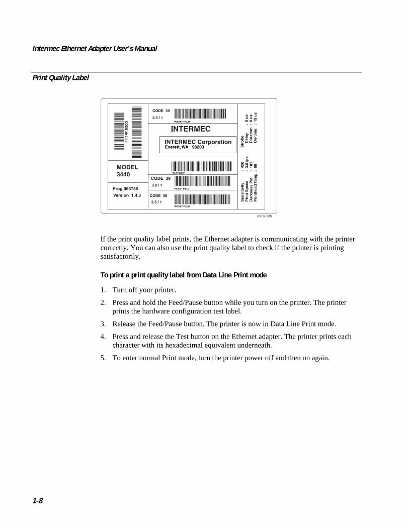
If the print quality label prints, the Ethernet adapter is communicating with the printercorrectly. You can also use the print quality label to check if the printer is printingsatisfactorily.
To print a print quality label from Data Line Print mode
1. Turn off your printer.
2. Press and hold the Feed/Pause button while you turn on the printer. The printerprints the hardware configuration test label.
3. Release the Feed/Pause button. The printer is now in Data Line Print mode.
4. Press and release the Test button on the Ethernet adapter. The printer prints eachcharacter with its hexadecimal equivalent underneath.
5. To enter normal Print mode, turn the printer power off and then on again.

code39 code39 Introducing the Ethernet Adapter
1-9
1To print a parameter list
• If you have firmware version 5.59 or higher, press the Test button twice.
AXIS 540+/542+ V5.56Jun 3 1998S/N: 00408C353354TCP/IP: enabledIP Address: 999. 999. 999. 999WINS: enabledStatus: Not RegisteredName: AXIS353354NetWare: enabledPrint server name: AXIS353354Microsoft Networks andLAN Server/Manager: enabledPrinter Name: AX353354. LP1Apple Ether Talk: disabledAXIS353354_LPT1AXIS353354_2
AXISI006
The printer prints a label giving the following information on the Ethernet adapter:
• Serial number
• TCP/IP enabled or disabled
• IP address
• WINS enabled or disabled
• Registration status
• Ethernet adapter name
• NetWare enabled or disabled
• Print server name
• Microsoft networks and LAN server or LAN manager enabled or disabled
• Printer name
• Apple EtherTalk enabled or disabled
To return to the factory default settings
1. Turn off the printer or remove the power cord to turn off the Ethernet adapter.
2. Press and hold down the Test button.
3. While continuing to press the Test button, simultaneously turn on the Ethernetadapter by turning on the printer or replacing the power cord. Keep the Test buttonpressed for at least 5 seconds after restoring power until the Network LED flashesat 1-second intervals.

Intermec Ethernet Adapter User’s Manual code39 code39
1-10
4. Release the Test button and wait at least five LED flashes.
5. Press and hold the Test button again until the Network LED remains constantly lit.
Restart the Ethernet adapter by turning it off and on. The Ethernet adapter is now resetto factory default settings.
Note: The node address parameter (NODE_ADDR) and IP address (IP_ADDR) willremain unchanged, but all other parameters are reset. If you want to change the nodeor IP address, you may do so via the general property page, using the AXIS NetPilot.

Connecting the Ethernet Adapter
2


code39 code39 Connecting the Ethernet Adapter
2-3
2This chapter explains how to connect your Ethernet adapter to your network and howto install and integrate your Ethernet adapter in your network environment. Thischapter also explains how to set up your Ethernet adapter for TCP/IP.
Connecting the Ethernet Adapter to Your NetworkBoth the internal and external Ethernet adapters are pre-configured with a unique nodeaddress that is identical to the serial number. You can change the node address usingthe AXIS NetPilot or any standard Web browser, if required.
Note: You need an external power supply for the external Ethernet adapter on certainprinters. (See page 1-3 for the models that require an external power supply.) Makesure that the external power supply is marked with the correct mains voltage. SeeAppendix B for the power consumption specifications.
To connect the Ethernet adapter to your network
1. Note the Ethernet adapter’s serial number. The serial number is on the bottom ofthe external adapter and on the back panel by the 10BaseT connector on the internaloption. You need the serial number during the network configuration.
2. Turn off the printer or disconnect the Ethernet adapter’s external power supply.
3. Plug the external Ethernet adapter into the printer’s parallel port.
4. Connect a 10BaseT cable to the 10BaseT connector.
5. Turn on the printer and, if necessary, connect the external power supply to theexternal Ethernet adapter.
The Network LED flashes when the Ethernet adapter is connected to your network. Ifthe Network LED is not flashing, make sure that the Ethernet adapter is connectedproperly and that the correct cable is attached.
If you have firmware version 5.59 or higher, make sure the Ethernet adapter is workingby pressing the Test button to print a print quality label. If you have a firmware versionlower than 5.59, you can print a print quality label by putting the printer in Data LinePrint mode first. For help, see “Using the Test Button” in Chapter 1.
Guide to Installing the Ethernet Adapter on Your NetworkAfter connecting the Ethernet adapter to your network, you are now ready to install theEthernet adapter. Choose the method of installation based on your printingrequirements and the type of network you use. Proceed with the appropriate installationmethod from the next table.
Intermec Ethernet Adapter User’s Manual code39 code39
2-4
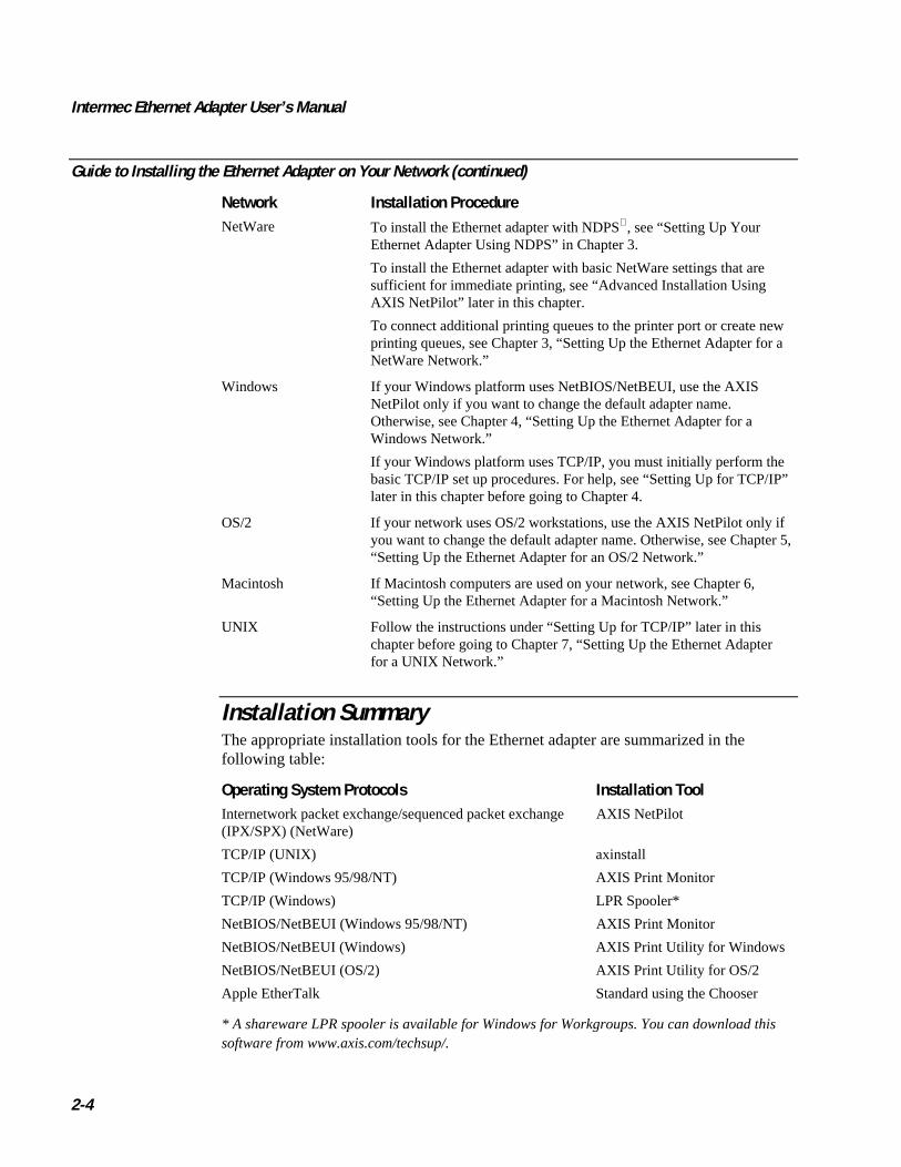
Guide to Installing the Ethernet Adapter on Your Network (continued)
Network Installation ProcedureNetWare To install the Ethernet adapter with NDPS, see “Setting Up Your
Ethernet Adapter Using NDPS” in Chapter 3.
To install the Ethernet adapter with basic NetWare settings that aresufficient for immediate printing, see “Advanced Installation UsingAXIS NetPilot” later in this chapter.
To connect additional printing queues to the printer port or create newprinting queues, see Chapter 3, “Setting Up the Ethernet Adapter for aNetWare Network.”
Windows If your Windows platform uses NetBIOS/NetBEUI, use the AXISNetPilot only if you want to change the default adapter name.Otherwise, see Chapter 4, “Setting Up the Ethernet Adapter for aWindows Network.”
If your Windows platform uses TCP/IP, you must initially perform thebasic TCP/IP set up procedures. For help, see “Setting Up for TCP/IP”later in this chapter before going to Chapter 4.
OS/2 If your network uses OS/2 workstations, use the AXIS NetPilot only ifyou want to change the default adapter name. Otherwise, see Chapter 5,“Setting Up the Ethernet Adapter for an OS/2 Network.”
Macintosh If Macintosh computers are used on your network, see Chapter 6,“Setting Up the Ethernet Adapter for a Macintosh Network.”
UNIX Follow the instructions under “Setting Up for TCP/IP” later in thischapter before going to Chapter 7, “Setting Up the Ethernet Adapterfor a UNIX Network.”
Installation SummaryThe appropriate installation tools for the Ethernet adapter are summarized in thefollowing table:
Operating System Protocols Installation ToolInternetwork packet exchange/sequenced packet exchange(IPX/SPX) (NetWare)
AXIS NetPilot
TCP/IP (UNIX) axinstall
TCP/IP (Windows 95/98/NT) AXIS Print Monitor
TCP/IP (Windows) LPR Spooler*
NetBIOS/NetBEUI (Windows 95/98/NT) AXIS Print Monitor
NetBIOS/NetBEUI (Windows) AXIS Print Utility for Windows
NetBIOS/NetBEUI (OS/2) AXIS Print Utility for OS/2
Apple EtherTalk Standard using the Chooser
* A shareware LPR spooler is available for Windows for Workgroups. You can download thissoftware from www.axis.com/techsup/.

code39 code39 Connecting the Ethernet Adapter
2-5
2Setting Up With AXIS NetPilot
AXIS NetPilot is part of the AXIS Print Utilities, which comes on the CD-ROM ordisks shipped with your Ethernet adapter. AXIS NetPilot runs on any of the Windowsplatforms:
• Windows 3.1
• Windows 95
• Windows 98
• Windows NT
• Windows for Workgroups
• WinOS/2 window under OS/2
Installing AXIS Print UtilitiesUse one of the next procedures to install AXIS NetPilot on your PC or host.
To install AXIS Print Utilities on a Windows client
• Run n:\windows\setup
where n is your CD-ROM or disk drive
An installation wizard appears to guide you through the installation.
To install AXIS Print Utilities on an OS/2 client
• Run n:\os2\install
where n is your CD-ROM or disk drive
An installation wizard appears to guide you through the installation.
Using AXIS NetPilotWhen you start AXIS NetPilot, the program searches the network for new Ethernetadapters that have not yet been installed. For fastest results, make sure the Ethernetadapter is connected to your printer and your printer is on. If the program finds any newadapters, you have the option of installing them. To proceed, select the Ethernet adapteryou want to install and start the Axis Installation Wizard.
Note: The parameters entered during installation are not permanent; you can changethem according to your network printing requirements.
Intermec Ethernet Adapter User’s Manual code39 code39
2-6
AXIS NetPilot Installation Wizard
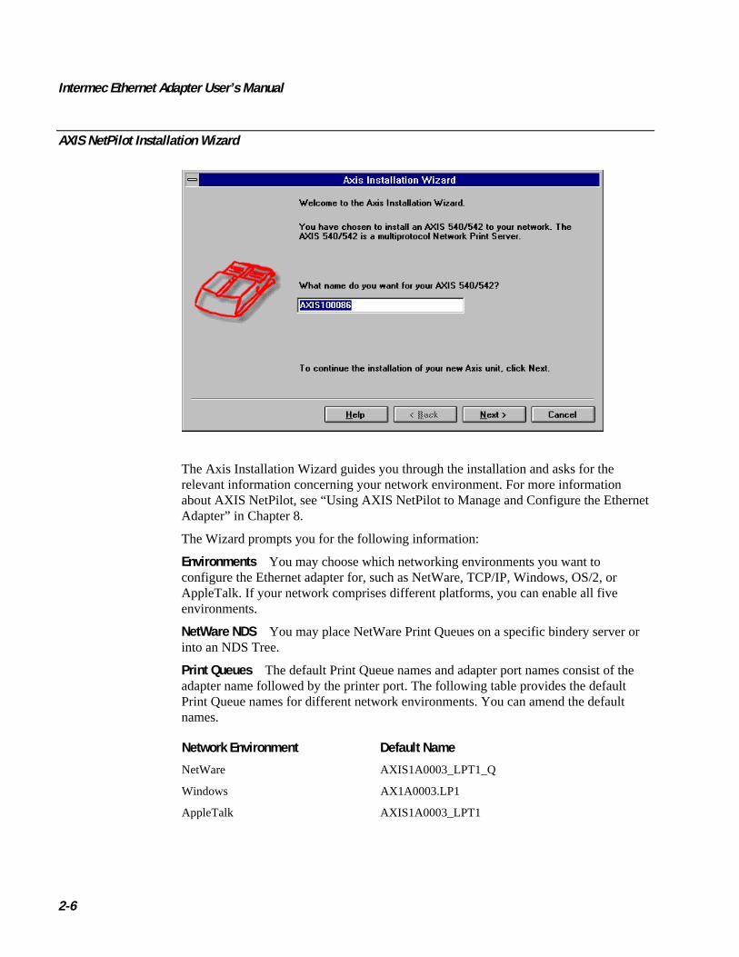
The Axis Installation Wizard guides you through the installation and asks for therelevant information concerning your network environment. For more informationabout AXIS NetPilot, see “Using AXIS NetPilot to Manage and Configure the EthernetAdapter” in Chapter 8.
The Wizard prompts you for the following information:
Environments You may choose which networking environments you want toconfigure the Ethernet adapter for, such as NetWare, TCP/IP, Windows, OS/2, orAppleTalk. If your network comprises different platforms, you can enable all fiveenvironments.
NetWare NDS You may place NetWare Print Queues on a specific bindery server orinto an NDS Tree.
Print Queues The default Print Queue names and adapter port names consist of theadapter name followed by the printer port. The following table provides the defaultPrint Queue names for different network environments. You can amend the defaultnames.
Network Environment Default Name
NetWare AXIS1A0003_LPT1_Q
Windows AX1A0003.LP1
AppleTalk AXIS1A0003_LPT1
code39 code39 Connecting the Ethernet Adapter
2-7
2IP Address During the Axis Installation Wizard, you can choose the method theEthernet adapter employs for obtaining an IP address. Dynamic host configurationprotocol (DHCP), address resolution protocol (ARP), reverse address resolutionprotocol (RARP), and bootstrap protocol (BOOTP) are supported. You can also selectto set the IP address manually. Refer to “Setting Up for TCP/IP” later in this chapter formore information about setting the IP address.
Test Label Do not print a test label from AXIS NetPilot. To print a test label, see“Printing a Test Label” later in this chapter.
Unless you want to connect or create additional printing queues, the installation for theNetWare environment is now completed.
After AXIS NetPilot finishes configuring the Ethernet adapter, wait about one minutebefore trying to communicate with the Ethernet adapter.
Note: If printing is not satisfactory, you can change the parameters to yourrequirements.
For information on advanced functions, please refer to the AXIS Network Print ServerTechnical Reference. You may download this or other technical information over theInternet by accessing the Axis web site at www.axis.com.
Setting Up for TCP/IPBefore you begin setting up your Ethernet adapter for TCP/IP, you need the followinginformation and network privileges:
Information or Privilege Description
System privileges You need root privileges on your UNIX system or administratorprivileges on a Windows NT server.
Ethernet address You need to know the Ethernet address of your Ethernet adapterto perform the installation. The Ethernet address is based on theserial number of your adapter. This means that an Ethernetadapter with a serial number of 00408C100086 will have acorresponding Ethernet address of 00 40 8C 10 00 86. The serialnumber of your external adapter is located on the underside of theadapter. The serial number for the internal adapter is located onthe back of your printer by the 10BaseT connector.
IP address Unless you are downloading the IP address using DHCP, youmust acquire an unused IP address from your networkadministrator.
Note: Do not use the example IP address when installing your Ethernet adapter.Always consult your network administrator before assigning an IP address.
Intermec Ethernet Adapter User’s Manual code39 code39
2-8
Downloading the IP AddressYou can set the IP address of the Ethernet adapter by using DHCP, ARP, RARP, orBOOTP. All methods are enabled by default. If you want to disable any of the methods,you can do so when installing the Ethernet adapter using the AXIS NetPilot InstallationWizard. For help, see “Setting Up With AXIS NetPilot” earlier in this chapter.
From the Axis Installation Wizard you can also set the IP address manually.
The main characteristics of the supported methods are described below:
Name Characteristics
DHCP DHCP (dynamic host configuration protocol) is available in Windows NTand UNIX systems and allows for the automatic but temporary assignmentof IP addresses from a central pool. When enabled, DHCP causes theselected host to automatically allocate and download an unused IP address,default router address, and net mask to the requesting adapter. It alsoprovides validation data that defines how long the IP addresses remainvalid.
To fully benefit from this method, the Ethernet adapter also supports theWindows Internet Name Service (WINS) host name resolution protocol,which is available in Windows NT networks.
ARP Available in UNIX, Windows 95, Windows 98, and Windows NT, ARP(address resolution protocol) is an easy method to download IP addresses toindividual adapters. You cannot use this method over routers.
RARP RARP (reverse address resolution protocol) is available in UNIX and itdownloads the IP address to each device automatically. It requires a RARPdaemon on your system and operates within a single network segment only.A request made to an active RARP daemon initiates a search of the EthernetAddress Table for an entry matching the adapter's Ethernet address. If amatching entry is found, the daemon downloads the IP address to theadapter.
BOOTP BOOTP (bootstrap protocol) is available in UNIX and is quite similar toRARP, although it can operate on the entire network. It requires a BOOTPdaemon on your system. A request made to an active BOOTP daemoninitiates a search of the Boot Table for an entry matching the adapter'sEthernet address. If a matching entry is found, the daemon downloads theIP address to the adapter.
code39 code39 Connecting the Ethernet Adapter
2-9
2Using DHCP in Windows
1. Edit or create a scope in the DHCP manager of the DHCP daemon. This scopeshould contain the following parameters:
• Range of IP addresses
• Subnet mask
• Default router IP address
• WINS server IP address(es)
• NetBIOS over TCP/IP node type
• Lease duration
2. Activate the scope.
The Ethernet adapter automatically downloads the DHCP parameters. You do not needto restart the adapter to download the IP address.
If you intend to use Windows Internet Name Service (WINS), you must include at leastone WINS server IP address in the DHCP scope. Immediately after the adapter receivesthe IP address, the Ethernet adapter registers its host name and IP address at the WINSserver.
The Ethernet adapter can automatically download a customized configuration file froma trivial file transfer protocol (TFTP) server. To download from a TFTP server, add thename of the configuration file and the IP address of the TFTP server to your DHCPscope. The configuration file downloads immediately after the Ethernet adapter hasreceived its IP address.
Using ARP in Windows 95, 98, or NT
1. Start a DOS window.
2. Type the following command:
arp -s nnn.nnn.n.nnn nn-nn-nn-nn-nn-nn
ping nnn.nnn.n.nnn
arp -d nnn.nnn.n.nnn
where:
nnn.nnn.n.nnn is the IP address for the Ethernet adapter
nn-nn-nn-nn-nn-nn is the Ethernet address for the Ethernet adapter
Example:
arp -s 192.168.3.191 00-40-8c-10-00-86
ping 192.168.3.191
arp -d 192.168.3.191
Intermec Ethernet Adapter User’s Manual code39 code39
2-10
The host will return Reply from 192.168.3.191 ... or a similar message. Thisreply indicates that the address has been set and communications established.
Using ARP in UNIX
• Type the following command:
arp -s host_name nn:nn:nn:nn:nn:nn temp
ping host_name
where:
host_name is the name mapped to the Ethernet adapter’s IP address. Formore information about mapping a host name to the IPaddress, see “Assigning a Host Name to the IP Address” laterin this chapter.
nn:nn:nn:nn:nn:nn is the Ethernet address for the adapter.
Example:
arp -s npsname 00:40:8c:10:00:86 temp
ping npsname
The host will return npsname is alive or a similar message. This message indicatesthat the address has been set and communications established.
When you execute the ping command for the first time, you may experience a longerresponse time than is usual.
The ARP command can vary between different UNIX systems. Berkeley SystemDistribution (BSD) type systems expect the host name and node address in reverseorder. Furthermore, IBM AIX systems require the additional argument ether. Forexample:
arp -s ether host name 00:40:8c:10:00:86 temp
Using RARP in UNIXNote: If you are an IBM AIX user, you will probably not have access to a RARPdaemon. If this is the case, you can use either the ARP or BOOTP method instead.
1. Append the following line to your Ethernet Address table, typically by using thecommand /etc/ethers :
nn:nn:nn:nn:nn:nn host_name

code39 code39 Connecting the Ethernet Adapter
2-11
2where:
nn:nn:nn:nn:nn:nn is the Ethernet adapter’s Ethernet address.
host_name is the name mapped to the Ethernet adapter’s IP address. For more information about mapping a host name to the IP address, see “Assigning a Host Name to the IP Address” later in this chapter.
Example:
00:40:8c:10:00:86 npsname
2. Update, if necessary, your host table and alias name databases, as required by yoursystem.
3. If it is not already running, start the RARP daemon, typically by using thecommand rarpd -a .
4. Restart the Ethernet adapter to download the IP address.
Using BOOTP in UNIX
1. Append the following entry to your boot table, typically by editing the file/etc/bootptab .
host_name :ht=ether:vm=rfc1048:\
:ha= nnnnnnnnnnnn :ip= nnn.nnn.n.nnn :\
:sm= nnn.nnn.nnn.n :gw= nnn.nnn.n.n
where:
host_name is the name mapped to the Ethernet adapter’s IP address. Formore information about mapping a host name to the IPaddress, see “Assigning a Host Name to the IP Address” laterin this chapter.
nnnnnnnnnnnn is the Ethernet address for the Ethernet adapter.
nnn.nnn.n.nnn is the IP address for the Ethernet adapter.
nnn.nnn.nnn.n is the subnet mask, which corresponds to the net mask (NET_MASK).
nnn.nnn.n.n is the gateway field, which corresponds to the default router address (DEF_ROUT).
Example:
npsname:ht=ether:vm=rfc1048:\
:ha=00408c100086:ip=192.168.3.191:\
:sm=255.255.255.0:gw=192.168.1.1

Intermec Ethernet Adapter User’s Manual code39 code39
2-12
2. Update, if necessary, your host table and alias name databases as required by yoursystem.
3. If it is not already running, start the BOOTP daemon, typically by using thecommand bootpd .
4. Restart the Ethernet adapter to download the IP address, default router address, andnet mask.
The Ethernet adapter can automatically download a customized configuration file froma TFTP server. To download a file from a TFTP server, add the name of theconfiguration file and the IP address of the TFTP server to your boot table. Theconfiguration file downloads immediately after the Ethernet adapter has received its IPaddress.
Assigning a Host Name to the IP AddressIf you are using host names, you can map a unique host name to the acquired IPaddress. Refer to your system manuals or to your network administrator for instructionson how the name mapping is performed on your system.
The Ethernet adapter supports WINS, which you should use to set the IP address usingDHCP.
If the host name is not mapped to an IP address, you can use the IP address in place ofthe host name when downloading the IP address.
Installing the LPR SpoolerFor Windows 3.1, Windows for Workgroups, Windows 95, and Windows 98, you needan LPR spooler to print via TCP/IP. You can download the spooler software andself-extracting file WLPRS41.EXE, from www.axis.com/techsup.
To install the LPR spooler
1. Give the Ethernet adapter an IP address and ping it. For help, see “Downloadingthe IP Address” earlier in this chapter.
2. Download the spooler (the WLPRS41.EXE file) into a temporary directory.
3. Extract the spooler by running WLPRS41.EXE.
4. Start SETUP.EXE and select a spooler directory or create a new directory.
5. Create a Queue setup file by accepting the default value.
6. Start the “Windows LPR spooler” program.
7. Define a new Queue by selecting Setup, Queues, and then Define New Queue.

code39 code39 Connecting the Ethernet Adapter
2-13
28. Fill out the dialog box:
Local Spool File : nameRemote Queue Name : prXRemote Host Name : xxx.xxx.x.xxx
where:
name is the name of the printer.
prX is the logical printer.
xxx.xxx.x.xxx is the IP address for the Ethernet adapter.
9. Click OK.
Since the LPR spooler must be running in order to print, put the spooler in the“Startup” group.
Note: WLPRS41.EXE is a shareware program. Please register if you are using it formore than a test period.
Configuring the Centronics Interface TimingBefore you can print to an Intermec printer, you must set the Centronics interfacetiming to standard.
To set the Centronics interface timing
1. Download the IP address. For help, see “Downloading the IP Address” earlier inthis chapter.
2. Open the Ethernet adapter’s home page. For help, see “Using a Web Browser toManage and Configure the Ethernet Adapter” in Chapter 8.
3. From the home page, click the Configuration button.
4. From the Configuration screen, click Output.
5. Click the down arrow by Centronics Interface Timing LPT1 and select STNDRD.
6. Click the Submit Output Settings button.
7. Close your Web browser.
Printing a Test LabelYou can use the test label provided on the disks or CD-ROM that came with yourEthernet adapter to make sure you can print a file sent from your host or PC. Thissection explains how to print the test label using an LPR spooler or a file transferprotocol (FTP) session from a Windows 95, 98, and NT environment.
Intermec Ethernet Adapter User’s Manual code39 code39
2-14
You need to complete the following installation processes before you can print the testlabel:
• Install the Ethernet adapter in your network.
• Download the IP address for the Ethernet adapter. For help, see “Downloading theIP address” earlier in this chapter.
• If you are using the LPR spooler, download and install the LPR spooler. For help,see “Installing the LPR Spooler” earlier in this chapter.
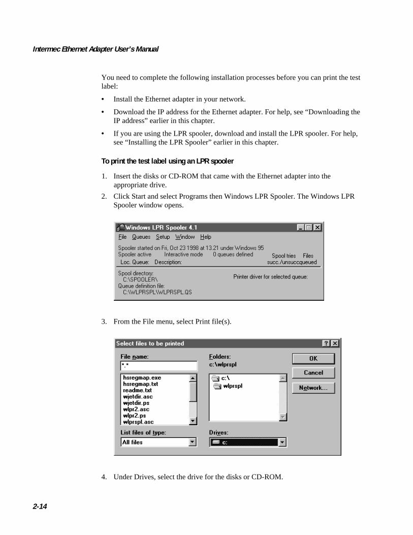
To print the test label using an LPR spooler
1. Insert the disks or CD-ROM that came with the Ethernet adapter into theappropriate drive.
2. Click Start and select Programs then Windows LPR Spooler. The Windows LPRSpooler window opens.
3. From the File menu, select Print file(s).
4. Under Drives, select the drive for the disks or CD-ROM.

code39 code39 Connecting the Ethernet Adapter
2-15
25. Open the Intermec folder and select test_lbl.
6. Click OK.
7. Select the printer you want to print to and click OK.
To print the test label using an FTP session
1. Insert the disks or CD-ROM that came with the Ethernet adapter into theappropriate drive.
2. From an MS DOS prompt, login to the Ethernet adapter using the command ftphost_name , where host_name is the name assigned to your Ethernet adapter, forexample npserver.
3. Enter root as user id and pass as password.
4. Enter the following command to print the test label:
put a:\intermec\test_lbl pr1
Note: Change a: to match the drive for the disks or CD-ROM.
5. Log out using the command quit , bye , or exit depending on your FTP version.


Setting Up the Ethernet Adapter for aNetWare Network
3

code9 code9 Setting Up the Ethernet Adapter for a NetWare Network
3-3
3This chapter explains how to install, configure, and manage your Ethernet adapter ina NetWare network.
Setting Up Your Ethernet Adapter Using NDPSThe Ethernet adapter supports Novell Distributed Print Services (NDPS), which isNovell’s new generation protocol for printer administration and printing.
Before you can install the Ethernet adapter, you must install NDPS and an HP Gatewayon your NetWare file server. The HP Gateway is included with the NDPS software andis automatically installed together with NDPS. The Ethernet adapter uses the HPGateway when communicating with an NDPS printer.
You can disable the NDPS feature by setting the HP_JETADMIN parameter to NO.
Please refer to the appropriate Novell and Hewlett Packard documentation for furtherdetails about NDPS and the HP Gateway.
Note: To run NDPS, you must have NetWare version 4.11 or higher.
To install the connected printers as public access printers
1. Make sure that the HP Gateway is configured to automatically create a publicaccess printer before you connect the Ethernet adapter to the network.
2. Connect the Ethernet adapter to the NetWare network.
As soon as the HP Gateway finds the Ethernet adapter, it automatically creates a publicaccess printer. Any user may have access to the public access printer, which is foundwith the Novell Printer Manager.
To install the connected printers as controlled access printers
1. Make sure that the HP Gateway is not configured to automatically create a publicaccess printer before you connect the Ethernet adapter to the network.
2. Connect the Ethernet adapter to the NetWare network.
3. Use the NetWare Administrator to create an NDPS printer as an object in thedirectory. As directory objects, access to the printers is controlled and they are nolonger available as public access printers.
The controlled access printer is found in the Novell Printer Manager’s NDS object list.
Intermec Ethernet Adapter User’s Manual code39 code39
3-4
Printing MethodsThe following overview explains the advantages and limitations of the two supportedNetWare printing methods.
Print Server ModeThe Ethernet adapter logs into a file server(s) and repeatedly polls the print queues forprint jobs. In this fashion, the Ethernet adapter emulates a NetWare print server, whichis a workstation running PSERVER. It provides high printing speed with low networkload and is the recommended mode for medium to large networks. Each adapter inPSERVER mode occupies one NetWare license.
Advantages Print server mode has high performance (typically 150 to 400K persecond).
Limitations Print server mode requires a NetWare user license for each Ethernetadapter to file server link.
Remote Printer ModeThe Ethernet adapter connects itself to a PSERVER NetWare program running on thefile server or to a dedicated workstation running PSERVER.EXE. It then automaticallyreceives print jobs from the file server. In this fashion, the Ethernet adapter emulates aworkstation running the NetWare remote printer software RPRINTER or NPRINTER.This mode is only recommended for small networks where the number of NetWare userlicenses is a major issue.
Advantages Remote printer mode does not require NetWare user licenses.
Limitations Remote printer mode has lower performance (typically 20 to 70K persecond for NetWare Loadable Module [NLM]) and causes higher network load.
Advanced Installation Using AXIS NetPilotHaving installed your Ethernet adapter, your Ethernet adapter now appears in thecontents of the Network Print Servers folder located in the AXIS NetPilot mainwindow. Use the NetWare Network Environment window to connect or createadditional print queues to your Ethernet adapter.
To access the NetWare Network Environment window
1. Select the required Ethernet adapter from the Network Print Server folder.
2. Choose Network from the Setup menu or click on the Network Icon on the toolbar.
3. If you are not already logged on to your NetWare file server, a dialog box willprompt you to do so.
Setting Up the Ethernet Adapter for a NetWare Network
3-5
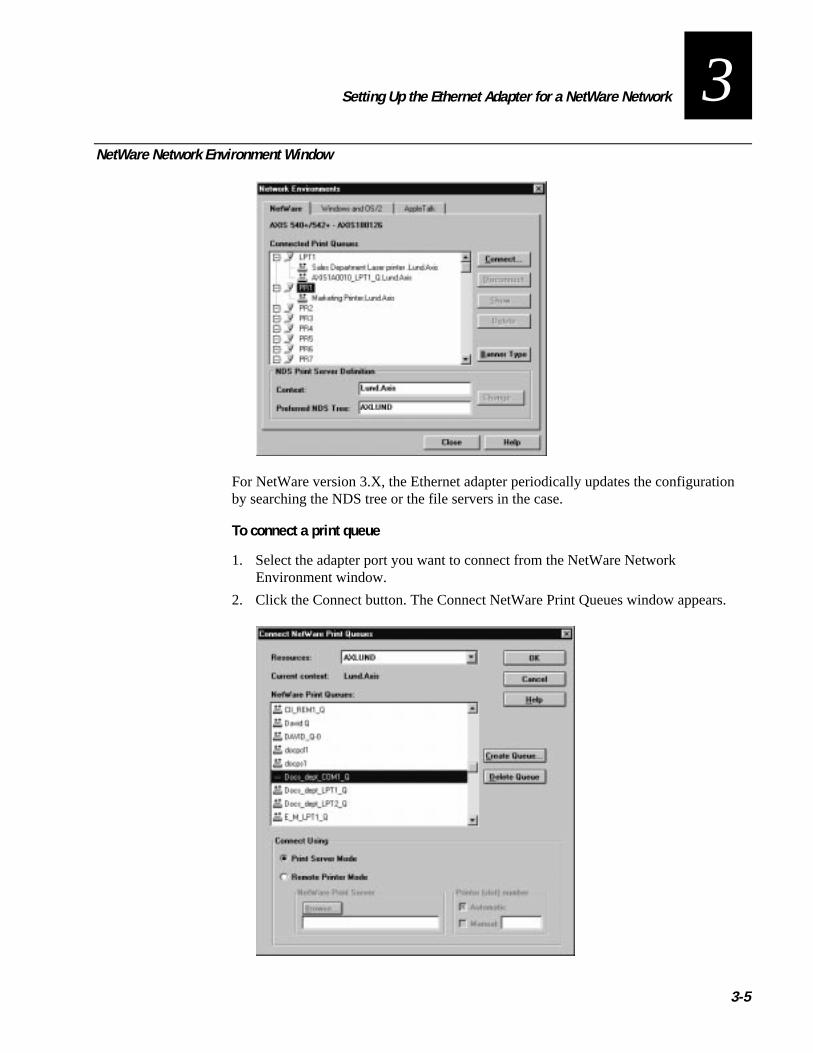
3NetWare Network Environment Window
For NetWare version 3.X, the Ethernet adapter periodically updates the configurationby searching the NDS tree or the file servers in the case.
To connect a print queue
1. Select the adapter port you want to connect from the NetWare NetworkEnvironment window.
2. Click the Connect button. The Connect NetWare Print Queues window appears.

Intermec Ethernet Adapter User’s Manual
3-6
3. Select the location of the print queue from the Resources box.
4. Select an existing NetWare print queue for connection to the server port then go toStep 7. If you want to create a print queue, click Create Queue and go to Step 5.
5. Type the queue name in the Create Queue dialog window. If you want to create aqueue in the NDS tree, type the name of the volume where you want to store thequeue. Click OK.
6. Select the newly created queue from the queue list.
7. Define the method of printing by selecting Print Server Mode or Remote PrinterMode. If you selected Print Server mode, go to Step 10; otherwise, go to Step 8.
8. Select an appropriate NetWare Print Server name that will work with the Ethernetadapter by using the Browse button. You cannot type or edit the name manually.
9. If you want to define a remote printer number slot manually, check the Manual boxand type the desired number in the box.
10. Click the OK button to return to the Network Environments window.

Setting Up the Ethernet Adapter for aWindows Network
4


Setting Up the Ethernet Adapter for a Windows Network
4-3
4This chapter describes how to use the AXIS Print Utilities for printing in the Windowsenvironment.
Using the AXIS Print Monitor for Windows 95, 98, and NTThe AXIS Print Monitor is supplied on the CD-ROM or disks that are provided withyour Ethernet adapter. You use the AXIS Print Monitor software for network printingwithin Windows 95, 98, and NT environments. It allows the Ethernet adapters to beconnected in the same simple fashion as a local printer port and, once installed, to beautomatically initialized upon system startup.
Install the AXIS Print Monitor now if you have not already done so. For help, see“Installing AXIS Print Utilities” in Chapter 2.
To change the default name or amend any of the Ethernet adapter default parameters,use the AXIS NetPilot or any standard Web browser. For help, see Chapter 8,“Managing and Configuring the Ethernet Adapter.”
About the AXIS Print MonitorAXIS Print Monitor is a Windows component developed for peer-to-peer printing underWindows 95, 98, and NT. It allows you to send print jobs directly to the Ethernetadapter.
Note: You can use the AXIS Print Monitor for DOS printing when installed onWindows NT platforms. However, in Windows 95 or 98, DOS printing is only possiblefrom a client workstation in a client/server configuration. If DOS peer-to-peer printingis necessary from a Windows 95 or 98 platform, use the AXIS Print Utility forWindows.
Printing EnvironmentsThe AXIS Print Monitor supports printing over NetBIOS/NetBEUI and TCP/IP (LPR).To enable printing in any of the environments, ensure that the desired protocol isrunning on your client.
Peer-to-Peer PrintingInstall the AXIS Print Monitor on each workstation performing peer-to-peer printing.Once installed, the AXIS Print Monitor then allows you to access all network printers,just as if the printers were connected directly to your workstation. Peer-to-peer printinghas the following benefits:
• You can easily monitor the status of your printers by enabling error conditionpop-up messages.
• You do not have to rely on a server.
Intermec Ethernet Adapter User’s Manual
4-4
Client/Server PrintingDo not enable pop-up messages on the server as the status of shared printers will not bereported to the client platforms. Pop-up messages are only issued on the server.
User DialogAlthough the AXIS Print Monitor user dialog varies depending on the platform you areusing (Windows 95, Windows 98, Windows NT 4.0, or Windows NT 3.5X), thefunctionality is exactly the same.
Note: Use the printer driver provided with the printer even if the desired printer isavailable from the manufacturer and model lists. Using the driver provided with yourprinter ensures that you are using the latest software.
Using the AXIS Print Monitor With Windows 95 or 98Follow the next procedures to install printer ports from a Windows 95 or 98workstation.
To install printer ports with NetBIOS or NetBEUI
1. To start the Add Printer Wizard, select Settings then Printers from the Start Menuand double-click the Add Printer icon.
2. After clicking Next in the first dialog box, select Local Printer because the Ethernetadapter emulates a local printer port. Click Next.
3. Choose the appropriate printer driver for your printer. If the desired printer driverappears within the displayed manufacturer and model lists dialog box, highlightyour selection, click Next, and go to Step 6. If your printer is not in the model list,go to Step 4.
4. Click the Have Disk button. Insert the CD-ROM or disks provided with youradapter, select the appropriate drive, and click OK.
5. Select the printer driver and click Next.
6. Select an AXIS Printer Port from the Available Ports list. The port name appears asname.LP1, where name is AX followed by the last six digits of the Ethernetadapter’s serial number, for example AX100086. Click the Configure Port button.
7. Check the pop-up message box in the Configure AXIS Printer Ports dialog box tohave error condition pop-up messages appear. Define the frequency at which theerror messages appear after retry. Click Next.
8. Enter an appropriate name for your printer and click Next.
9. Click Finish.

Setting Up the Ethernet Adapter for a Windows Network
4-5
4To install printer ports with TCP/IP
Note: To be able to print using LPR, you must install the Ethernet adapter in theTCP/IP environment. For help, see “Setting Up for TCP/IP” in Chapter 2.
1. To start the Add Printer Wizard, select Settings then Printers from the Start Menuand double-click the Add Printer icon.
2. After clicking Next in the first dialog box, select Local Printer as the Ethernetadapter emulates a local printer port. Click Next.
3. Choose the appropriate printer driver for your printer. If the desired printer driveralready appears within the displayed manufacturer and model lists dialog box,highlight your selection, click Next, and go to Step 6. If your printer is not in themodel list, go to Step 4.
4. Click the Have Disk button. Insert the CD-ROM or disks provided with youradapter, select the appropriate drive, and click OK.
5. Select the printer driver and click Next.
6. Select an AXIS LPR Port and then click OK. Available LPR ports appear asport_name@internet_address or port_name@host_name, for [email protected]. To install a new LPR port, select the Printers@LPR port.Click the Configure Port button.
7. Check the pop-up messages box in the Configure AXIS LPR Ports dialog box tohave error condition pop-up messages appear. Define the frequency at which theerror messages appear after retry. Click OK then Next.
Note: The dummy port cannot be used for printing and consequently cannot beconfigured.
8. Enter an appropriate name for your printer and click Next.
9. Click Finish.
Continue with the following steps only if you want to install a printer to a new LPRport and have chosen Printers@LPR port in Step 6.
10. The printer you have defined appears in the Printers Folder. Right-click the printerobject and select Properties from the Context menu.
11. Click the details tab within the Properties page and then click Add Port to displaythe available monitors.
12. Click the radio button “other.” Select AXIS Port and then click OK.
13. Select LPR (TCP/IP) as your choice of network protocol and click OK.
14. Enter the IP address or the host name of your adapter and assign an appropriateLogical Printer. Click OK.
15. The LPR port appears in the list of available ports. Click OK.
Intermec Ethernet Adapter User’s Manual
4-6
16. Configure the port as described in Step 7.
17. Click the Apply button.
The Ethernet adapter printer port is now installed.
Using the AXIS Print Monitor With Windows NT 4.0Follow the next procedure to install Axis Printer Ports from a Windows NT 4.0workstation.
To install printer ports with NetBIOS or NetBEUI
1. To start the Add Printer Wizard, select Settings then Printers from the Start menuand double-click on the Add Printer icon.
2. Select My Computer, as the Ethernet adapter emulates a local printer port.
3. Click Add Port in the Available ports dialog box, select AXIS Port and click NewPort.
4. Select the AXIS Port you want to add. The port appears as name.LP1, where nameis AX followed by the last six digits of the Ethernet adapter’s serial number, forexample AX100086. Click OK.
5. Close the Printer Ports window.
6. Click the Configure Port button. Check the pop-up messages box in the ConfigureAXIS LPR Ports dialog box to have error condition pop-up messages appear.Define the frequency at which the error messages appear after retry. Click OK thenNext.
7. Choose the appropriate printer driver for your printer. Click Next and go to Step 10.Go to Step 8 if your printer does not feature within the model list.
8. Click the Have Disk button. Insert the CD-ROM or disks provided with youradapter, select the appropriate drive, and click OK.
9. Select the printer driver and click Next.
10. Enter an appropriate name for your printer and click Next.
11. Choose whether you want to share the printer with other network users and clickNext.
12. Click Finish.

Setting Up the Ethernet Adapter for a Windows Network
4-7
4To install printer ports with TCP/IP
Note: To be able to print using LPR, you must install the Ethernet adapter in theTCP/IP environment. For help, see “Setting Up for TCP/IP” in Chapter 2.
1. To start the Add Printer Wizard, select Settings then Printers from the Start menuand double-click on the Add Printer icon.
2. Select My Computer because the Ethernet adapter emulates a local printer port.Click Next.
3. If the LPR Printer port you want to use already appears in the available ports list,go to Step 8. If not, click Add Port and continue with Step 4.
4. Select AXIS port from the list of available monitors in the Printer Port dialog box.Click the New Port button.
5. Select LPR (TCP/IP) as your choice of network protocol and click OK.
6. From the Add AXIS LPR Port dialog box, enter the IP address or host name of youradapter and define a Logical printer name. Click OK.
7. Click OK to return to the Printer Ports dialog box. Click Close.
8. Select an AXIS LPR Port you want to use and then click OK. Available LPR portsappear as port_name@internet_address or port_name@host_name, for [email protected].
9. Click Configure Port. Check the pop-up messages box in the Configure AXIS LPRPorts dialog box to have error condition pop-up messages appear. Define thefrequency at which the error messages appear after retry. Click OK.
10. Having selected and configured the chosen port, click Next.
11. Choose an appropriate printer driver for your printer. If the desired printer driveralready appears within the displayed manufacturer and model lists dialog box,highlight your selection, click Next, and go to Step 14. Go to Step 12 if your printerdoes not feature within the models list.
12. Click the Have Disk button. Insert the CD-ROM or disks provided with youradapter, select the appropriate drive, and click OK.
13. Select the printer driver and click Next.
14. Enter an appropriate name for your printer and click Next.
15. Choose whether you want to share the printer with other network users and clickNext.
16. Click Finish.

Intermec Ethernet Adapter User’s Manual
4-8
Using the AXIS Print Monitor With Windows NT 3.5XFollow the next procedure to install Axis printer ports from a Windows NT 3.5Xworkstation.
To install printer ports with NetBIOS or NetBEUI
1. Open the Print Manager and select Create Printer from the Printer Menu.
2. Enter an appropriate name in the Printer Name field.
3. Choose an appropriate printer driver for your printer from the manufacturer andmodel lists displayed and then go to Step 6. Go to Step 4 if your printer does notfeature within the model list.
4. Select Other in the driver list. Insert the CD-ROM or disks provided with youradapter, select the appropriate drive, and click OK.
5. Select the printer driver.
6. Select Other in the “Print to” list box.
7. Select Axis Port in the list of available Print Monitors and click OK.
8. Select the port you want to add and then click OK. The port appears as name.LP1,where name is AX followed by the last six digits of the Ethernet adapter’s serialnumber, for example AX100086.
9. Click on Settings. Check the pop-up messages box in the Configure AXIS LPRPorts dialog box to have error condition pop-up messages appear. Click OK.
10. Click OK.
To install printer ports with TCP/IP
Note: To be able to print using LPR, you must install the Ethernet adapter in theTCP/IP environment. For help, see “Setting Up for TCP/IP” in Chapter 2.
1. Open the Print Manager and select Create Printer from the Printer Menu.
2. Enter an appropriate name in the Printer Name field.
3. Choose an appropriate printer driver for your printer from the drop-down Driverlist. If the desired printer driver already appears in the displayed manufacturer andmodel lists dialog box, go to Step 6. Go to Step 4 if your printer does not appear inthe model list.
4. Select Other in the driver list. Insert the CD-ROM or disks provided with youradapter, select the drive, and click OK.
5. Select the printer driver you want to install.
6. Select Other from the “Print to” drop-down list.

Setting Up the Ethernet Adapter for a Windows Network
4-9
47. Select AXIS Port from the list of available Print Monitors in the Print Destination
dialog box. Click OK.
8. Select LPR (TCP/IP) as your choice of network protocol and click OK.
9. From the Add LPR port dialog box, enter the IP address or host name of youradapter and define a Logical printer name. Click OK to return to the Create Printerdialog box.
10. Select the LPR port you want to use from the “Print to” drop-down list. The portsappear as port_name@internet_address or port_name@host_name, for [email protected].
11. Click the Settings button. Check the pop-up messages box in the Configure AXISLPR Ports dialog box to have error condition pop-up messages appear. Define thefrequency at which the error messages appear after retry. Click OK to return to theCreate Printer dialog box.
12. Having selected and configured the chosen port, click Next.
13. Select whether you want to share the printer with other network users. Click OK.
The printer properties are displayed within an appropriate dialog box that allows you torefine your printer setup.
The Axis printer is now installed and will appear as an icon within the Print Manager.
Using the Microsoft LPD Monitor for Windows NTThis section provides instructions for setting up your Ethernet adapter for line printer(LPR) or line printer daemon (LPD) printing over the TCP/IP protocol using the built-in Microsoft LPD monitor.
If you have not already done so, you should perform the TCP/IP basic setup proceduresprior to installing a printer for LPD printing. For help, see “Setting Up for TCP/IP” inChapter 2.
To see if TCP/IP is already installed, click the Network icon in the Control Panel. If theTCP/IP Printing entry appears, then TCP/IP is already installed. Close the Networkfolder and go to the procedure to install a printer later in this section. If the TCP/IPPrinting entry does not appear, go to the Windows NT 4.0 procedure to prepare forLPR/LPD printing or to the Windows NT 4.0 procedure to install the TCP/IP protocolstack.

Intermec Ethernet Adapter User’s Manual
4-10
Using the Microsoft LPD Monitor With Windows NT 4.0This section describes how to set up Windows NT Server version 4.0 for LPR printing.
To prepare for LPR/LPD printing
1. Open the Control Panel and click the Network icon.
2. Select Protocols.
3. Add TCP/IP Protocol.
4. Select Services.
5. Add MS TCP/IP Printing.
To install a printer for LPD printing
1. Open the Control Panel and open the Printers folder.
2. Click Add Printer, select My Computer and then go to Next.
3. Select Add Port. In Printer Ports, choose LPR Port and then click New Port.
4. In Add LPR compatible printer, enter the name or IP address of the Ethernetadapter as the print server to provide LPD.
5. Enter “pr1,” “pr2,” … “pr8” as the name of the printer or the print queue on thatserver.
6. Choose a suitable printer driver for your printer and go to Next.
7. Enter a printer name and go to Next.
8. Select Shared to share the printer over the network.
9. Enter a share name.
10. Click Next and then Finish.
To use a shared printer from a Windows 95 or 98 client
1. Open the Control Panel.
2. Open the Printers folder.
3. Click Add Printer.
4. Select Network Print Server and then go to Next.
5. Enter the path for the network printer or browse the network to find and select it.
6. Go to Next and then Finish.
Setting Up the Ethernet Adapter for a Windows Network
4-11
4Using the Microsoft LPD Monitor With Windows NT 3.5XThis section describes how to set up Windows NT Server versions 3.5 and 3.51 forLPD printing.
To install the TCP/IP protocol stack
1. In the Control Panel, select Network.
2. Click Add Software.
3. Select “TCP/IP Protocol and related components” and then click Continue.
4. Check “TCP/IP Network Printing Support” and then click Continue.
5. Select path and then click Continue.
6. Click OK in the Network Settings dialog box.
To install a printer for LPD printing
1. In the Control Panel, click the Print Manager.
2. In the Printer menu, select Create Printer.
3. In the Printer Name field, type a name for your printer.
4. Choose a suitable printer driver for your printer.
5. In the Print to field, select Other.
6. In the Print Destinations dialog box, choose LPR Port and then click OK. The AddLPR Compatible Printer dialog box appears.
7. In the Name or Address field, type the IP address or the alias name of your Ethernetadapter. The alias name must be defined in the hosts file on your server. The hostsfile is normally located in /winnt35/system32/drivers/etc/hosts.
8. In the Name of Printer on the Machine field, type the logical printer number youwant to use, such as pr1. Click OK.
9. Click OK to complete the installation.
Intermec Ethernet Adapter User’s Manual
4-12
Setting Up the Ethernet Adapter to Use an LPR SpoolerIf you are using an LPR spooler to print via TCP/IP, follow the next instructions toinstall your Ethernet adapter with the LPR spooler. For help installing the LPR spooler,see “Installing the LPR Spooler” in Chapter 2.
To use an LPR spooler for Windows 3.1 and Windows for Workgroups
1. Start Control panel.
2. Click Printers.
3. Install a printer driver.
4. Click Connect.
5. Choose your queue. For example:
C:\spooler\myprinter
To use an LPR spooler for Windows 95 or 98
1. From the Start menu, click Settings then Printers.
2. Double-click Add Printer. The Add Printer Wizard window appears.
3. Click Next.
4. Select Local Printer and click Next.
5. Select your printer and click Next.
6. Select your queue. For example:
C:\spooler\myprinter
Using the AXIS Print Utility for WindowsThe AXIS Print Utility for Windows is supplied on the CD-ROM or disks that camewith your Ethernet adapter and is the tool for network printing within Windows forWorkgroups and Windows 3.1 environments.
You should install this utility now if you have not already done so. For help, see“Installing AXIS Print Utilities” in Chapter 2.

Setting Up the Ethernet Adapter for a Windows Network
4-13
4About AXIS Print Utility for WindowsAXIS Print Utility for Windows is a dual purpose application for network printing inthe Windows environment. It has two fundamental purposes:
• Install and maintain Ethernet adapter printer ports as Windows printer ports.
• Capture and monitor print jobs directed to the Ethernet adapter ports. Print jobs aredirected through a spool directory either at your local hard disk (peer-to-peer mode)or at the file server (client/server mode). The printer port status of your Ethernetadapter may be monitored and pop-up notification messages can be generated,keeping you informed of completed print jobs or any problematic condition.
For more information about AXIS Print Utility for Windows, see the online help.
To use AXIS Print Utility for Windows, Microsoft Network (NetBIOS/NetBEUI) mustbe running.
To print in peer-to-peer mode, AXIS Print Utility for Windows must be running. TheAXIS Print Utility for Windows is not needed on the client platforms for client/serverprinting.
Note: If you want to change the default name of your Ethernet adapter or amend any ofthe default parameters, you may do so using the AXIS NetPilot or any standard Webbrowser. For help, see Chapter 8, “Managing and Configuring the Ethernet Adapter.”
Peer-to-Peer vs. Client/Server PrintingWindows for Workgroups and Windows 3.1 users requiring access to a network printerin Peer-to-Peer mode need to install the AXIS Print Utility for Windows software ontheir workstations. Users may then add the required network printer to their systemsand use the printer as if it was connected directly to their workstation. Peer-to-peerprinting affords the following benefits:
• You can monitor the printer status at all times and be notified when a print job iscomplete.
• You do not have to rely on a server.
Client/server operation requires only one user to install the AXIS Print Utility forWindows software onto their workstation. This user then adds the printer to his or herworkstation (the server) and shares the printer with other users on the network. Theother users (the clients) may connect to the printer through the server via the WindowsPrint Manager.
Client/server mode provides a way of maintaining queue ordering and job priority, butat a price:
• You cannot receive printer status or print job notification.
• The workstation set up as the server must be available at all times. It must also havethe capacity to handle the print jobs that pass through it.
Intermec Ethernet Adapter User’s Manual
4-14
Note: When using Client/Server mode, other users may still install the AXIS PrintUtility for Windows software to print in Peer-to-Peer mode. When using Client/Servermode, it is recommended that you set up the server only on a Windows for Workgroupsworkstation.
Note: AXIS Print Utility for Windows must be running when you print through yourEthernet adapter. We strongly recommend that you copy the AXIS Print Utility iconinto your StartUp folder.
To use peer-to-peer printing
Note: In order to print to a network printer, Windows 3.1 requires the installation ofnetwork support, such as the LAN Server or LAN Manager Workstation software.
1. Double-click the AXIS Print Utility icon.
2. In the Port menu, click Add.
3. In the NPS Port list, select the Ethernet adapter port. The port appears as name.LP1,where name is AX followed by the last six digits of the Ethernet adapter’s serialnumber, for example AX100086. However, you can change the name using AXISNetPilot.
4. Accept or change the suggested Windows port name and type any requiredcomment in the Description field. Make a note of the Windows port name as youwill need this later, then click OK to install the Windows port.
5. In the Port menu, click Connect to bring up the Windows Printers dialog box.
6. Select a printer driver from the list of Installed Printers (or click Add to install anew driver), then click Connect.
7. Select the Windows port name from Step 4 (this name can be found at the bottomof the Ports list).
8. Click OK to close the Connect dialog box and Close to close Printers.
The setup is completed and you can now print through your Ethernet adapter.

Setting Up the Ethernet Adapter for a Windows Network
4-15
4To set up the server for client/server printing
Note: In order to print to a network printer, Windows 3.1 requires the installation ofnetwork support, such as the LAN Server or LAN Manager Workstation software.
1. Choose a workstation that you want to use as a server for network printing. Theserver must be available at all times and must have sufficient hard disk space forspooling print jobs.
2. Make sure that the printer sharing option is enabled. (Open Network Setup, clickSharing; check the “I want to be able to allow others to print to my printer(s)” box).
3. Install AXIS Print Utility for Windows on the server.
4. Set up your Ethernet adapter as described in the previous procedure.
5. Open Print Manager and select your printer.
6. In the Printer menu, select Share Printer As.
7. Type a printer name in the Share As field (this is the printer name seen by theclients).
8. Check the Re-share at Startup box, then click OK.
The server setup is now complete. Set up the clients as described below.
To set up the clients for client/server printing
Note: In order to print to a network printer, Windows 3.1 requires the installation ofnetwork support, such as the LAN Server or LAN Manager Workstation software.
1. In the Control Panel, select Printers.
2. Select a printer driver from the list of Installed Printers, or click Add to install anew driver. Click Connect.
3. Select Network in the Device Name list and select a local port (LPT1 to LPT3) toredirect to your network printer.
4. In the Show Shared Printers on list, select the server from Server Setup above.
5. In the Shared Printers list, select the printer you want to use.
6. Click OK; click OK, then click Close.
7. Exit the Control Panel.
The client setup is completed and you can now print through your Ethernet adapter.
Intermec Ethernet Adapter User’s Manual
4-16
Windows Clients Using LANtasticFrom any Windows client, the Ethernet adapter may also be used for network printingwithin LANtastic environments.
LANtastic users may use the AXIS utilities in exactly the same manner as described inthe preceding Windows sections, using a choice of Axis utility software that is guidedby the type of Windows client employed:
• Refer to “Using the AXIS Print Utility for Windows” earlier in this chapter if youare using a Windows for Workgroups client.
• Refer to “Using the AXIS Print Monitor for Windows 95, 98, and NT” earlier inthis chapter if you are using either a Windows 95, 98, or NT client.
Make sure that your LANtastic client is running the desired printing protocols.
Setting Up the Ethernet Adapter for anOS/2 Network
5

Setting Up the Ethernet Adapter for an OS/2 Network
5-3
5This chapter describes how to set up your Ethernet adapter for printing in the OS/2environment.
Using the AXIS Print Utility for OS/2The installation and setup operations are performed with the AXIS Print Utility forOS/2. You should install this utility now if you have not already done so. For help, see“Installing AXIS Print Utilities” in Chapter 2.
You can change the default name of your Ethernet adapter or amend any of the defaultparameters by using any standard Web browser or AXIS NetPilot from any Windowsplatform that is connected to your network or WinOS/2 window under OS/2. For help,see Chapter 8, “Managing and Configuring the Ethernet Adapter.”
You do not need the AXIS Print Utility for OS/2 on the client platforms when using aclient/server configuration.
AXIS Print Utility for OS/2 is a dual purpose application for network printing in theOS/2 environment. Its fundamental purpose is to:
• Install and maintain the Ethernet adapter printer port as an OS/2 printer port.
• Capture and monitor print jobs directed to the Ethernet adapter port. Print jobs maybe directed through a spool directory either at your local hard disk or at the fileserver. You can monitor the printer port status of your Ethernet adapter and pop-upnotification messages can inform you of completed print jobs or any problematiccondition.
The NetBEUI protocol must be active. If this protocol is not active, use MPTS/LAPS(LAN Server) or SETUP (LAN Manager) to activate it.
Note: If you are using OS/2 version 2.X and want to print through TCP/IP, werecommend that you use the IBM TCP/IP for OS/2 product. It supports the LPD andinteractive FTP print methods.
To install the Ethernet adapter
1. When AXIS Print Utility for OS/2 is running, click Install to install your Ethernetadapter. The port appears in the list as name.LP1, where name is AX followed bythe last six digits of your adapter number, for example AX100086.LP1. However,you can change this name using AXIS NetPilot.
2. Select the port that you want to install, then click Install.
3. Repeat this procedure for each server using the Ethernet adapter.
Note: The AXIS Print Utility for OS/2 must be running in order to print using yourEthernet adapter.

Intermec Ethernet Adapter User’s Manual
5-4
Integrating Your Ethernet Adapter Into the OS/2Environment
To use your Ethernet adapter on an OS/2 network, you have to create a print queue forthe printer and adapter. After you have created the print queue, you can make the printqueue a shared resource so that other OS/2 clients can use the same printer.
Creating a Print Queue
To create a print queue with OS/2 version 1.X
1. Double-click the Print Manager icon, click Setup, then select Printers.
2. Click Add to make a new printer definition, then type a name of your choice in theName field.
3. Select \PIPE\name.LP1 from the Device list, then select a printer driver suitable foryour printer.
4. Click Add, then click OK to confirm the printer definition.
5. Click Setup, then select Queues.
6. Click Add to create a print queue, and type a name in the Name field.
7. Click Add, then click OK to confirm the queue definition.
To create a print queue with OS/2 version 2.X and OS/2 Warp
1. Double-click the Templates folder, then drag the Printer icon out to the WorkplaceShell (or into a folder) while holding the right mouse button down.
2. Type a name of your choice in the Name field.
3. Select \PIPE\name.LP1 from the Port list, and select a printer driver suitable foryour printer from the Standard Printer list.
4. Click OK to confirm the printer definition.
Sharing the Print QueueA print queue must be made a shared resource before it can be accessed from othercomputers (clients or other servers).
Open an OS/2 window and issue the following command:
NET SHARE queue_name /PRINT

Setting Up the Ethernet Adapter for an OS/2 Network
5-5
5where:
queue_name is the name of the queue created.
To share a printer resource when using OS/2 Warp with IBM Peer service
1. Click the right mouse button on the printer object.
2. Select Share and then Start sharing. In the dialogue box, enter a Description.
3. Select the check-box Start sharing at LAN workstation start-up.
4. Click OK.
The setup is completed and you can now print through your Ethernet adapter.
To share a printer resource when using LAN server 4.0
1. Open LAN Server Administration.
2. Open your domain and then Resource Definition.
3. Drag and drop a printer from the template.
4. Enter the Alias name, then select a Server name and the previously created SpoolerQueue Name.
5. Click OK.
The setup is completed and you can now print through your Ethernet adapter.


Setting Up the Ethernet Adapter for aMacintosh Network
6

Setting Up the Ethernet Adapter for a Macintosh Network
6-3
6This chapter describes how to set up your Ethernet adapter for printing in theAppleTalk environment.
Installing Using the Chooser WindowTo perform the basic configuration in the Apple EtherTalk environment, open theChooser window and select a printer. You need to create your own printer driver ornetwork compatible application to work with Intermec printers.
You can change the default name of your Ethernet adapter or amend any of the defaultparameters. However, to access the configuration file from a Macintosh, you need FTPsupport such as MacTCP, Fetch, or Anarchie.
Communications Support and ProtocolsThe Ethernet adapter allows your printer driver to communicate directly with theprinter and consequently facilitates complete functional control over print jobs, such asautomatic downloading of fonts not resident in the printer.
This functionality has backward compatibility with older Macintosh computers, whichmeans that the Ethernet adapter can generate appropriate responses to Macintoshprinter queries, when the connected printer does not support bi-directionalcommunication.
Binary communication protocol (BCP) and tagged binary communicationprotocol(TBCP) are communication protocols used by the serial and parallel ports of a printer.They allow 8-bit binary data in files concurrent with the use of some control charactersfor communication and print job control. TBCP is required for printing with a binarydata stream on some printers, such as HP printers.
Setting ParametersFrom within the Macintosh environment, you can set a small number of the parametersof the Ethernet adapter. You can select ASCII or either of the binary data protocols foryour printing and you can set the IP address, which enables you to configure andmanage your Ethernet adapter from any standard Web browser.
To set parameters
1. Open the Chooser.
2. Select a network printer driver.
3. Select the printer port that ends with “_CFG.”
4. Close the Chooser.
5. Open a text editor such as SimpleText.

Intermec Ethernet Adapter User’s Manual
6-4
6. Write a text file containing the following:
BINARY : YES
BINARY_TYPE : TBCP
INT_ADDR : 192.168.3.191
The BINARY parameter can take the values YES or NO. The BINARY_TYPEparameter can take the values BCP or TBCP. See the technical reference for moreinformation on these parameters.
Note: Do not use the IP address in the example above. Always consult yourNetwork Administrator before assigning an IP address.
7. Print the above text file. The adapter permanently stores the settings.
8. Open the Chooser and select the printer port you want to use for printingdocuments.
9. Finish the process by closing the Chooser.

Setting Up the Ethernet Adapter for aUNIX Network
7


Setting Up the Ethernet Adapter for a UNIX Network
7-3
7This chapter explains how to use axinstall to configure your Ethernet adapter.
Integrating Into the Host Printer SpoolerHaving performed the basic TCP/IP setup procedures in Chapter 2, you are now able toprint in interactive mode using LPR (LPD), FTP, or Reverse Telnet protocols.
However, if you need to integrate the Ethernet adapter into your host spooler, you canuse the Axis automatic installation script axinstall. This utility software is resident onthe Ethernet adapter, but it can also be uploaded to your host using FTP, so no disks arerequired. The axinstall script is also available on the CD-ROM or disks that came withyour adapter. Having completed this operation, the printer connected to the Ethernetadapter will appear as though they are directly connected to the host printer spooler.
To install the installation script axinstall using FTP
1. Login to the Ethernet adapter using the command ftp host_name , wherehost_name is the name assigned to your Ethernet adapter, for example npserver.
2. Enter root as user id and pass as password.
3. Download the script using the command get axinstall as shown in the examplebelow.
4. Log out using the command quit , bye , or exit depending on your FTP version.
The following is a typical FTP session for collecting the axinstall script.
> ftp npserver
connected to npserver.
220 AXIS 540/640 FTP Print Server v5.51 Apr 17 1998 ready.
Name (npsserver:thomas): root
331 User name ok, need password
Password: pass (not visible)
230 User logged in
ftp> get axinstall
200 PORT command successful.
150 Opening data connection for axinstall (192,36,253,4,13,223),(mode ascii).
226 Transfer complete.
local: axinstall remote: axinstall
61187 bytes received in 14 seconds (4.2 kbytes/s)
ftp> bye
221 Goodbye.
>
Intermec Ethernet Adapter User’s Manual
7-4
The axinstall script has now been downloaded to your host. Execute the script with thiscommand:
sh axinstall
Follow the step-by-step procedure through the installation. During the installation youwill be asked to select a print method; we suggest you choose LPD or, for morefunctionality, use the PROS filter or named pipe methods. Please refer to the followingpages if you need guidance on the choice of print methods.
The axinstall script will suggest one of the systems listed when started. If you do notfind the suggestion appropriate, then manually select any of the systems listed next:
• SunOS 4 (SUN BSD, Solaris 1.X)
• SunOS 5 (SUN SYS V, Solaris 2.X)
• AIX (IBM RS/6000, BULL DPX 20)
• HP-UX (HP 9000)
• BOS (BULL DPX 2)
• DEC OSF/1 (Digital Equipment, Alpha)
• ULTRIX (Digital Equipment, DEC)
• IRIX (Silicon Graphics, SGI)
• SCO UNIX (Santa Cruz Operation)
• FreeBSD (Berkeley UNIX)
• Generic BSD (Berkeley UNIX)
• Generic SYS V R3 (UNIX System V Release 3)
• Generic SYS V R4 (UNIX System V Release 4)
Print Methods on TCP/IP NetworksThe Ethernet adapter supports several different print methods in the TCP/IPenvironment. The utility axinstall will suggest a print method suitable for yourparticular UNIX system, but you might want to use another method depending on yourprinting requirements.
The next diagram shows the alternative data paths taken by some of the UNIX printmethods. This illustrates some of the advantages and limitations of the differentmethods. Use the following information to determine which method to adopt.

Setting Up the Ethernet Adapter for a UNIX Network
7-5
7Data Paths Taken by UNIX Print Methods
File to print
Printspooler
Filter/interfacemodel
Parallel port
Directlyconnected
printer
PROS printdaemon
Named pipe
FTPPROS B
LPDRTELNET
PROS APrinter
Ethernet adapter
DIRECTFTPRTELNET
AXISI.007
Line Printer DaemonThe line printer daemon (LPD) is a protocol for transferring print jobs between hosts.This is the recommended method for UNIX systems, but some System V versions donot support LPD.
Advantages LPD is easy to set up and install the Ethernet adapter as a remote queuein System V or to add a remote printer to /etc/printcap using the rm and rp fields(BSD).
Limitations Spooler features and printcap or lpr options (BSD), such as multiplecopies, are not available.
File Transfer ProtocolThe file transfer protocol (FTP) is used for transferring files between hosts.
Advantages FTP uses industry standard network software on the host.
Limitations FTP does not provide printer status logging. In the case of BSD, it mayconflict with other input or output filters and does not allow both input and outputfilters. In System V, you cannot use filters or interface programs.
PROSPROS is a protocol developed at Axis. It comes in two versions named pipe (PROS A)and filter (PROS B).
Intermec Ethernet Adapter User’s Manual
7-6
PROS AAdvantages The Ethernet adapter appears as a device to the system. This makes allfilter and model options available. It provides accounting and status logging andsupports bi-directional printing. You can view the printer information read back in a logfile.
Limitations A ‘C’ compiler is required to build the PROS A drivers.
PROS BAdvantages It provides accounting and status logging and supports bi-directionalprinting. You can view the printer information read back in a log file.
Limitations A ‘C’ compiler is required to build the PROS B drivers, and in the case ofBSD, it may conflict with other input or output filters. BSD does not allow both inputand output filters. You cannot use interface programs in System V.
Reverse TelnetReverse Telnet is often used for printing via a terminal server printer port and is onlyrecommended if you already have a Reverse Telnet driver installed.
Advantages Reverse Telnet is easy to set up with previously installed Reverse Telnetdrivers.
Limitations Reverse Telnet does not have status logging. Drivers are not suppliedwith the Ethernet adapter. Existing drivers may be slow.
Other SystemsThis section covers other UNIX and MVS systems you can use.
Other UNIX SystemsMost UNIX systems resemble either BSD or System V, so with some ingenuity asolution can also be devised for other variants.
If the system has BSD socket type networking support, then prosbsd (in the bsddirectory of the Ethernet adapter) can be used as a starting point. It receives print datafrom stdin and writes a log file to stderr . Nothing is written to stdout .
Alternatively, FTP may be used. You should use bsd/ftp_bsd or sysv/ftp_sysv asa starting point.
IBM MVS SystemsA sample JCL (job control language) script, jclex , is available in the mvs directory ofthe Ethernet adapter. It gives an example of how to print a file from a multiple virtualstorage (MVS) mainframe to an Ethernet adapter using FTP.
Setting Up the Ethernet Adapter for a UNIX Network
7-7
7Customizing Your Printing
The Ethernet adapter can alter the print data to match the type of printer you are using,so that you can use your desired print format on any type of printer. You can invoke thefollowing actions from the Ethernet adapter:
• You can change the character set to suit the printer.
• You can add strings before and after the print data.
• You can substitute strings within the print data.
• The Ethernet adapter can convert ASCII to PostScript.
• If the printer is busy, the Ethernet adapter can redirect print data to another printer.
• You can use Hex Dump mode to assist with printing problems.
If any of these actions are required, a logical printer is used to change the print databefore being sent to the printer port. There are eight logical printers that can be set upto filter the print data.
Edit the parameters in the Ethernet adapter’s configuration file to configure a logicalprinter. For more information, see Appendix A, “Configuration Parameters.” Thedefault logical printers settings are such that PR1 through PR4 cause no change to theflow of print data, while PR5 through PR8 add CR to LF control characters.
Logical Printer Changes to data
PR1 no change
PR2 no change
PR3 no change
PR4 no change
PR5 add CR to LF
PR6 add CR to LF
PR7 add CR to LF
PR8 add CR to LF
Converting Character SetsA common problem in a multiple host environment is that different hosts use differentASCII character sets. As a result, language-specific characters (such as å ü ô ñ) aresometimes printed incorrectly.
To avoid this problem, the Ethernet adapter assigns a character set conversion filter to alogical printer and then links that logical printer to the host causing the problem.

Intermec Ethernet Adapter User’s Manual
7-8
You can choose from several different filters within the PR1_CSET Character SetConversion. For more information, see Appendix A, “Configuration Parameters.” Theoutput from the conversion filter is always IBM PC Set 2 (Code Page 437), which youshould set up on your printer.
The following text provides an example scenario:
Problem Your network contains three hosts using the character sets IBM PC Set 2,ISO 8859-2, and DEC.
Solution In order for different hosts to direct their print jobs to the same printer, forinstance LPT1, you should assign each host to a separate logical printer and installcharacter set conversion filters. Edit the following entries in your configuration file:
PR1_CSET.: NONEPR2_CSET.: ISO>IBMPR3_CSET.: DEC>IBM
Result Logical printer PR1 prints data transparently without conversion. Logicalprinter PR2 converts ISO 8859-2 data to IBM PC Set 2. Logical printer PR3 convertsDEC data to IBM PC Set 2.
This arrangement will produce correct printouts for all language-specific characters.
Adding Strings Before and After Print JobsThese string functions provide a way to send printer control commands before and aftereach print job. They may be specified individually for each logical printer.
All strings are entered as hexadecimal byte values.
Example Assume that the logical printer PR5 is configured as a PostScript printer. Toappend the PostScript End of File character (Ctrl-D, hex 04) after each print job, editthe following entry in your configuration file:
PR5_AFT. : 04
Substituting StringsThe string substitution function performs search and replace operations on the printdata. The primary application is to replace printer control commands. Up to 20 stringsubstitutions may be specified individually for each logical printer.
All strings must be entered as hexadecimal byte values, and each match and substitutestring must be preceded by a count byte. For help, see Appendix A, “ConfigurationParameters.”
Example 1 To replace the UNIX New Line (hex 0A) with an ASCII New Line (hex0D 0A) for logical printer PR1, edit the following entry in your configuration file:
PR1_STR. : 01 0A 02 0D 0A

Setting Up the Ethernet Adapter for a UNIX Network
7-9
7where:
01 is the match string count byte (length of the match string)0A is the match string02 is the substitute count byte0D 0A is the substitute string
This is the default setting for logical printers PR5 through PR8.
Example 2 To replace the UNIX New Line (hex 0A) with an ASCII New Line (hex0D 0A) and the printer command ECG1 (hex 1B 47 31) with ECY (hex 1B 59) forlogical printer PR2, edit the following entry in your configuration file:
PR2_STR. : 01 0A 02 0D 0A 03 1B 47 31 02 1B 59
Note: Extensive use of string substitutions will decrease the throughput rate of theEthernet adapter.
Converting ASCII to PostScriptThe Ethernet adapter’s logical printers can translate ASCII print data into PostScriptformat. This translation makes it possible to print with a PostScript printer from a hostthat does not support PostScript. The conversion is selected by activating a filter thatconverts ASCII data into PostScript. This filter may be activated individually for eachlogical printer.
Example: The following entries in your configuration file allow print data applied toPR1 to pass without changes; print data applied to PR2 is converted from ASCII toPostScript, and PR3 data is searched. Any ASCII data is converted to PostScript, whilePostScript data is allowed to pass without change.
PR1_FILT. : NONEPR2_FILT. : POSTSCRPR3_FILT. : AUTO_PS
The AUTO_PS configuration is used when you are not sure if the print data is ASCII orPostScript.
When a logical printer is set for PostScript conversion, the printer needs to know thepage size, page orientation, page formats, and font to use. The default page size is A4and the default page orientation is Portrait. The following table lists the default valuesfor the page format parameters.
Page Format Parameter Default Value
Lines per page 66
Characters per line 0 (0=disable line wrap)
Characters per inch 10.0
Lines per inch 60
Left margin 30 (30 = 3.0 mm)
Top margin 50 (50 = 5.0 mm)

Intermec Ethernet Adapter User’s Manual
7-10
The PostScript font can be any font that is installed in the printer; if no font is specified,Courier will be used.
Example: The following entries are needed in your configuration file to set up logicalprinter number 2 for ASCII to PostScript conversion with the stated printingcharacteristics.
PR2_FILT. : POSTSCR (PostScript conversion on)PR2_SIZE. : LETTER (Page size = letter)PR2_ORNT. : LANDS (orientation = landscape)PR2_FORM. : 48 0 120 60 30 50 (48 LPP, 0 CPL, 12 CPI, 6 LPI, 3 mm left
margin and 5 mm top margins)PR2_FONT. : Helvetica (font = Helvetica)
Reading Back InformationThe Ethernet adapter supports bi-directional printing. The Ethernet adapter reads theinformation from the printer back on the parallel port when the parameter PRX_IN hasthe default setting of AUTO. However, the printer must support bi-directional printing.You can disable the communication through the PRX_IN parameter.
Example: Make the following entry in your configuration file to disable bi-directionalcommunication:
PR1_IN. : NONE (Read-back of information)
Debugging Using the Hex Dump ModeWhen you activate Hex Dump mode, the printer prints data and printer controlcommands as hexadecimal byte values rather than characters. Use this printout toinspect what control and print characters the printer receives in order to debug the moredifficult printing problems.
Example: The following is an example of the entries needed in your configuration fileto activate the Hex Dump mode for PR3:
PR3_DUMP.:YES (switch on hex dump mode for logical printer PR3)
Note: The label length for hex dump printouts is determined by the lines per label valueof the PostScript label format parameter.

Managing and Configuring the Ethernet Adapter
8

Managing and Configuring the Ethernet Adapter
8-3
8This section describes how you can change the Ethernet adapter’s parameter values.
IntroductionChoose the method you use to manage and configure your Ethernet adapter based onthe operating system protocols used in your network. This section covers the followingconfiguration methods:
• Using any standard Web browser
• Using AXIS NetPilot
• Using FTP
• Using Telnet
• Using SNMP
• Using HP administration tools
• Using Novell Utilities
The next table displays which methods you should use in the supported networkenvironments.
Operating System Protocols Configuration/Management Methods
IPX/SPX (NetWare) AXIS NetPilot, HP JetAdmin, Novell Utilities
TCP/IP (UNIX) Web Browser, FTP, Telnet, SNMP, HP WebJetAdmin
TCP/IP (Windows 95/98/NT) Web Browser, FTP, Telnet, SNMP, HP WebJetAdmin
TCP/IP (Windows) Web browser, FTP, Telnet, SNMP
NetBIOS/NetBEUI (Windows95/98/NT)
AXIS NetPilot
NetBIOS/NetBEUI (Windows) AXIS NetPilot
NetBIOS/NetBEUI (OS/2) AXIS NetPilot
Apple EtherTalk Web browser, Mac-FTP, AXIS NetPilot via a PCplatform within the same network.

Intermec Ethernet Adapter User’s Manual
8-4
Using a Web Browser to Manage and Configure theEthernet Adapter
Once you have established the Ethernet adapter in the TCP/IP environment, you canaccess the Ethernet adapter’s Web pages from any standard Web browser.
To access the home page of the Ethernet adapter
Note: The following procedure uses Internet Explorer.
1. Open your Web browser.
2. From the File menu, select Open.
3. Type the IP address of the Ethernet adapter in the Open dialog box.
Or type the host name in the Open dialog box.

Managing and Configuring the Ethernet Adapter
8-5
8The home page of your Ethernet adapter appears in your browser.
You can access links to the following services from the home page of the Ethernetadapter.
Service Description
From within the Configuration pages you can
• modify configuration parameters of the Ethernet adapter. For acomplete list of parameters, see Appendix B.
• enable and disable any of the available networking protocolsand modify their operation from appropriate configurationpages.
• change the node address.
• amend the root password.
When clicking on either Management or Configuration, you will beprompted to provide a user name and a password, unless you areusing the default values root and pass .

Intermec Ethernet Adapter User’s Manual
8-6
Home Page Services (continued)
Service Description
The Management Page allows you to reset the adapter and set theparameters to the factory default values. You may also view basicinformation about your Ethernet adapter, such as the currentsoftware version, Ethernet address, serial number, base URLaddress, and enabled networking protocols.
User-friendly links to other services are also provided, includingChange root password.
You may view the status of the connected printer ports from theStatus Page, examine the number of bytes printed, etc.
Maintains and displays a historical record of print jobs that alsodefines the user, logical printer, protocol, file size, elapsed time,and off-line time.
The Help page contains a short description of the configuration andmanagement activities that can be performed via the internal Webpages of the Ethernet adapter.
Note: Any network configuration should involve the Network Administrator.
Using AXIS NetPilot to Manage and Configure theEthernet Adapter
AXIS NetPilot is the recommended tool to use when you want to configure the Ethernetadapter in networks that support communication via NetWare, IPX/SPX, orNetBIOS/NetBEUI.
AXIS NetPilot allows you to
• change the Ethernet adapter’s parameter values.
• modify the network environments.
• monitor your printers.
• group logically connected adapters together.
• upgrade the Ethernet adapter with the latest available software. This feature iscovered in Chapter 9, “Updating the Software.”

Managing and Configuring the Ethernet Adapter
8-7
8Starting AXIS NetPilotTo start AXIS NetPilot just click the NetPilot icon in the folder where you installedAXIS NetPilot on your host computer.
Changing the Parameter ValuesFrom AXIS NetPilot you can change the adapter properties in two different ways. Youshould use the AXIS NetPilot property pages if you want to work with theconfiguration file via a user-friendly interface. The Parameter List Editor, which is avery fast and effective tool, should be used only if you are familiar with theconfiguration parameters.
After AXIS NetPilot finishes configuring the Ethernet adapter, wait about one minutebefore trying to communicate with the Ethernet adapter.
Property PagesThe property pages are the easy way to inspect and change any of the Ethernetadapter’s parameters. Each property page comprises an array of selection tabs that areappropriate to your operating environments. Each parameter can be edited by selectingthe relevant box on the property pages.
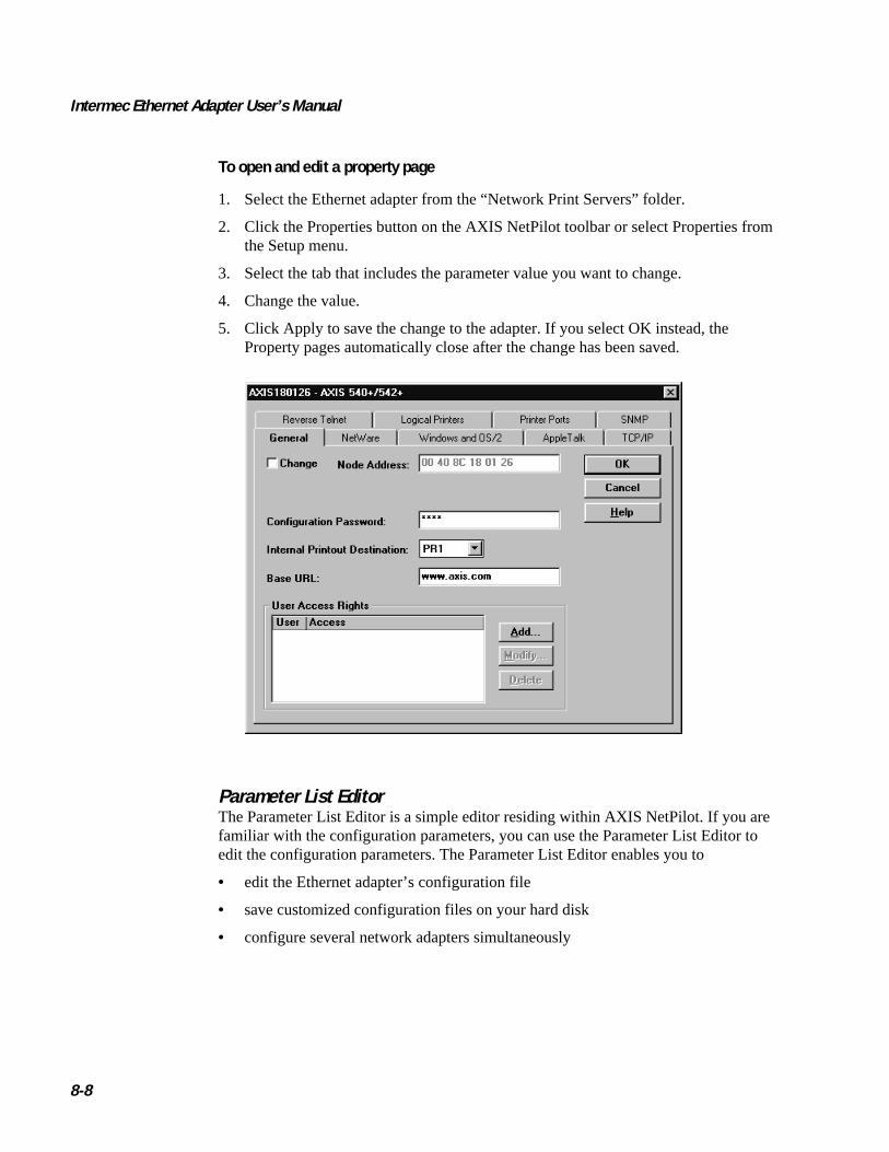
Intermec Ethernet Adapter User’s Manual
8-8
To open and edit a property page
1. Select the Ethernet adapter from the “Network Print Servers” folder.
2. Click the Properties button on the AXIS NetPilot toolbar or select Properties fromthe Setup menu.
3. Select the tab that includes the parameter value you want to change.
4. Change the value.
5. Click Apply to save the change to the adapter. If you select OK instead, theProperty pages automatically close after the change has been saved.
Parameter List EditorThe Parameter List Editor is a simple editor residing within AXIS NetPilot. If you arefamiliar with the configuration parameters, you can use the Parameter List Editor toedit the configuration parameters. The Parameter List Editor enables you to
• edit the Ethernet adapter’s configuration file
• save customized configuration files on your hard disk
• configure several network adapters simultaneously

Managing and Configuring the Ethernet Adapter
8-9
8To use the Parameter List Editor
1. Start the Parameter List Editor by selecting Parameter List from the Setup menu.
2. Upload a configuration file from an adapter or from your hard disk by selectingfrom File or from Print Server and click the Load button.
3. The configuration file will open in the editor. After you have done your desiredchanges, you can select to save the modified configuration file to one or moreadapters or alternatively to your hard disk. Just click Save after you have made yourchoice.
Modifying the Network EnvironmentsFrom the Network Environment window you can modify the network settings for eachsupported network environment.
To access the Network Environment window
1. Select the Ethernet adapter from the Network Print Servers folder.
2. Click on the Network button on the toolbar or select Network from the Setup menu.
3. Select the tab corresponding to the environment that you want to modify.
Monitoring PrintersFor the purpose of printer monitoring, the AXIS NetPilot allows you to create groups ofprinters. The AXIS NetPilot window displays the printers comprising each group. Toexamine the status of any printer within a group, click on the appropriate group foldericon. The status of each printer within a group appears and is marked by a colored icon.
You can create any number of groups and delete unwanted groups. Similarly, you caninclude or delete individual printers from any group.

Intermec Ethernet Adapter User’s Manual
8-10
Monitoring Printers (continued)
Grouping Logically Connected AdaptersFor the purpose of simplifying administration of the Ethernet adapter, the AXISNetPilot allows you to create groups of adapters. The adapters comprising each groupappear in the AXIS NetPilot window. To access any adapter within a group, simplyclick on the appropriate group folder icon.
You can create or delete any number of adapter groups.
Finding Printer InformationIt is possible to obtain extended information about the printers that appear in themonitoring window of the AXIS NetPilot. To open the Printer Information window,just click the desired printer and choose Printer Information from the File menu.
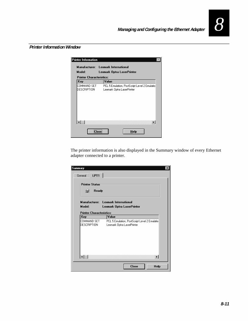
Managing and Configuring the Ethernet Adapter
8-11
8Printer Information Window
The printer information is also displayed in the Summary window of every Ethernetadapter connected to a printer.
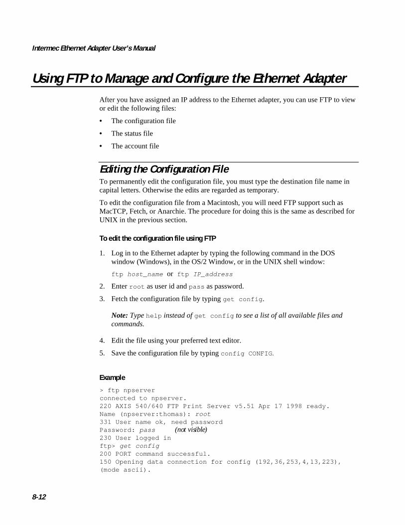
Intermec Ethernet Adapter User’s Manual
8-12
Using FTP to Manage and Configure the Ethernet AdapterAfter you have assigned an IP address to the Ethernet adapter, you can use FTP to viewor edit the following files:
• The configuration file
• The status file
• The account file
Editing the Configuration FileTo permanently edit the configuration file, you must type the destination file name incapital letters. Otherwise the edits are regarded as temporary.
To edit the configuration file from a Macintosh, you will need FTP support such asMacTCP, Fetch, or Anarchie. The procedure for doing this is the same as described forUNIX in the previous section.
To edit the configuration file using FTP
1. Log in to the Ethernet adapter by typing the following command in the DOSwindow (Windows), in the OS/2 Window, or in the UNIX shell window:
ftp host_name or ftp IP_address
2. Enter root as user id and pass as password.
3. Fetch the configuration file by typing get config .
Note: Type help instead of get config to see a list of all available files andcommands.
4. Edit the file using your preferred text editor.
5. Save the configuration file by typing config CONFIG .
Example
> ftp npserverconnected to npserver.220 AXIS 540/640 FTP Print Server v5.51 Apr 17 1998 ready.Name (npserver:thomas): root331 User name ok, need passwordPassword: pass (not visible)230 User logged inftp> get config200 PORT command successful.150 Opening data connection for config (192,36,253,4,13,223),(mode ascii).

Managing and Configuring the Ethernet Adapter
8-13
8226 Transfer complete.8588 bytes received in 0.24 seconds (35.63 kbytes/s)ftp> config CONFIG200 PORT command successful.150 Opening data connection for CONFIG (192,36,253,4,13,223),(mode ascii).226 Transfer complete.8588 bytes received in 0.45 seconds (19.04 kbytes/s)ftp> bye221 Goodbye.>
Viewing the Status FileThe status command shows which printer port the logical printers are assigned to andtheir current status.
To view the status file using FTP
1. Log in to the Ethernet adapter by typing the following command in the DOSwindow (Windows), in the OS/2 Window, or in the UNIX shell window:
ftp host_name or ftp IP_address
2. Enter root as user id and pass as password.
3. Fetch the status file by typing get status .
Note: Type help instead of get status to see a list of all available files andcommands.
4. View the status file using your preferred text editor.
Viewing the Account FileThe account file contains data concerning the 10 last print jobs. It specifies an internaljob number, the user that initiated the job, the protocol and logical printer that wasused, current status (Completed, Off-line, or Printing), number of bytes printed, elapsedtime, and off-line time.
To view the account file using FTP
1. Log in to the Ethernet adapter by typing the command in the DOS window(Windows), in the OS/2 Window, or in the UNIX shell window:
ftp host_name or ftp IP_address
2. Enter root as user id and pass as password.
3. Fetch the account file by typing get account .

Intermec Ethernet Adapter User’s Manual
8-14
Note: Type help instead of get account to see a list of all available files andcommands.
4. View the account file using your preferred text editor.
Using Telnet to Manage and Configure theEthernet Adapter
After you have assigned an IP address to the Ethernet adapter, you can use Telnet toview the accounting and status files of the Ethernet adapter and perform soft and hardresets.
Viewing the Accounting FileThe accounting file contains data concerning the last 10 print jobs. It specifies aninternal job number, the user that initiated the job, the protocol and logical printer thatwas used, current status (Completed, Off-line, or Printing), number of bytes printed,elapsed time, and off-line time.
To view the account file using Telnet
1. Log in to the Ethernet adapter by typing the command in the DOS window(Windows), in the OS/2 Window, or in the UNIX shell window:
telnet host_name or telnet IP_address
2. Enter root as user id and pass as password.
3. View the account file by typing account .
Note: Type help instead of account to see a list of all available commands.
The following example shows how to view the accounts file using Telnet from a UNIXwindow.
> telnet npserverTrying 192.36.253.96...Connected to npserver.Escape character is ‘^]’.
AXIS 540/640 TELNET Print Server v5.51 Apr 17 1998
AXIS 540/640 network login: rootPassword: pass (not visible)Root> account
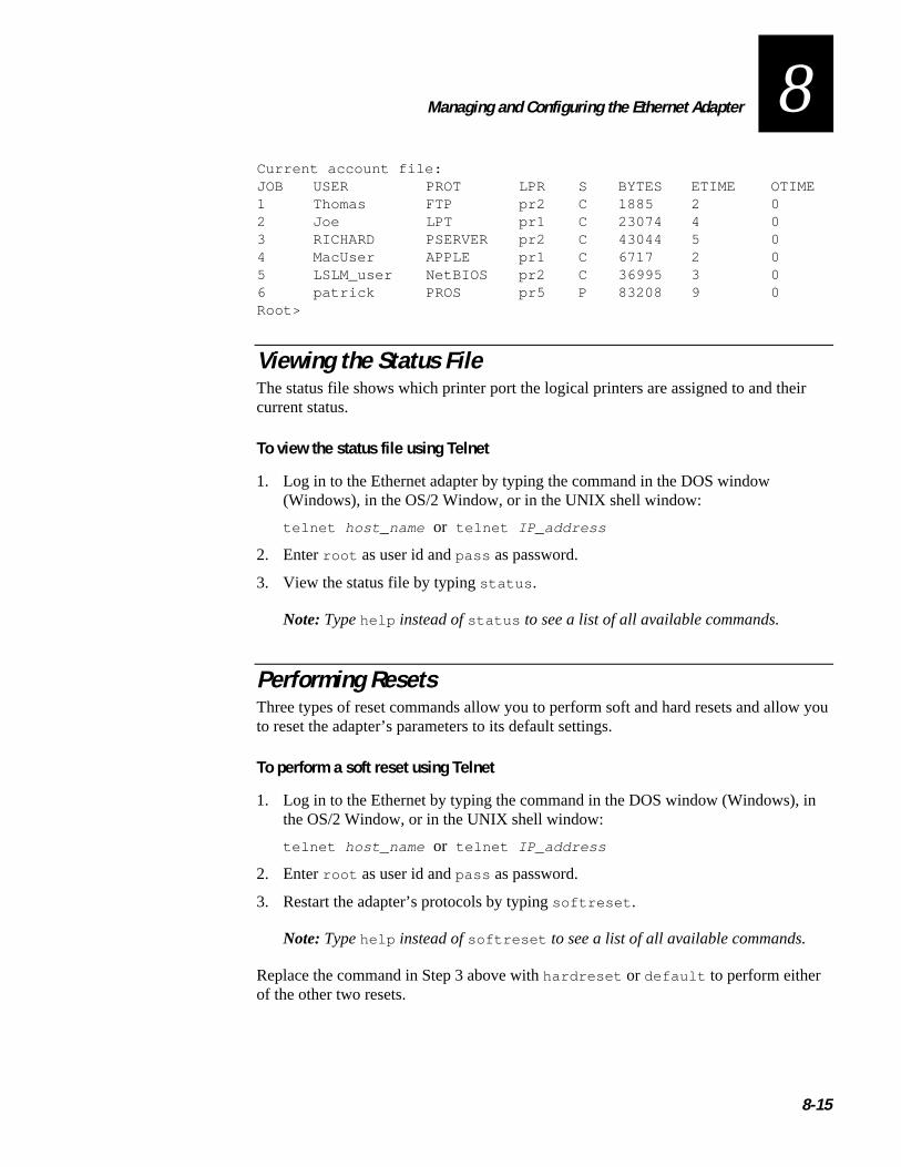
Managing and Configuring the Ethernet Adapter
8-15
8Current account file:JOB USER PROT LPR S BYTES ETIME OTIME1 Thomas FTP pr2 C 1885 2 02 Joe LPT pr1 C 23074 4 03 RICHARD PSERVER pr2 C 43044 5 04 MacUser APPLE pr1 C 6717 2 05 LSLM_user NetBIOS pr2 C 36995 3 06 patrick PROS pr5 P 83208 9 0Root>
Viewing the Status FileThe status file shows which printer port the logical printers are assigned to and theircurrent status.
To view the status file using Telnet
1. Log in to the Ethernet adapter by typing the command in the DOS window(Windows), in the OS/2 Window, or in the UNIX shell window:
telnet host_name or telnet IP_address
2. Enter root as user id and pass as password.
3. View the status file by typing status .
Note: Type help instead of status to see a list of all available commands.
Performing ResetsThree types of reset commands allow you to perform soft and hard resets and allow youto reset the adapter’s parameters to its default settings.
To perform a soft reset using Telnet
1. Log in to the Ethernet by typing the command in the DOS window (Windows), inthe OS/2 Window, or in the UNIX shell window:
telnet host_name or telnet IP_address
2. Enter root as user id and pass as password.
3. Restart the adapter’s protocols by typing softreset .
Note: Type help instead of softreset to see a list of all available commands.
Replace the command in Step 3 above with hardreset or default to perform eitherof the other two resets.

Intermec Ethernet Adapter User’s Manual
8-16
Using SNMP to Manage and Configure the Ethernet AdapterYou may use SNMP for remote monitoring of the Ethernet adapter. All major functionsapplicable to adapters are supported.
SNMP actually refers to a set of standards for network management, including aprotocol, a database structure specification, and a set of data objects. The Ethernetadapter SNMP implementation runs in the TCP/IP environment.
Network management system (NMS) software running on a host on your networkhandles the actual management. The NMS software sends messages referring to one ormore objects to the network devices.
A message can contain a question or an instruction to a device or an alarm triggered bya specific event in a device. Databases, called management information bases (MIBs),hold the objects. MIB-II is a standard database.
The Ethernet adapter supports all relevant parts of MIB-II. It also includes a privateenterprise MIB.
System Requirements for SNMPYour system must have the following to make full use of the Ethernet adapter SNMPsupport:
• NMS software that allows you to install private enterprise MIBs.
• A host that supports FTP to run the NMS software.
To add the AXIS MIB to your NMS software
1. Log in to the Ethernet adapter using FTP.
2. Upload the MIB file /snmp/axis.mib to the NMS host.
3. Install the AXIS MIB according to instructions in your NMS softwaredocumentation.
About AXIS MIBThe AXIS MIB contains a large number of objects that may be categorized as follows:
• Menu objects, which are used for viewing and changing the Ethernet adapter’sconfiguration from the NMS program. For a list of the Ethernet adapter’sparameters, see Appendix B.
• Printer status and unit administration objects, which are used for monitoringEthernet adapter print jobs and storing parameter changes permanently.
• Trap objects, which are used for alarms at various error conditions.
For technical details, you can view the MIB file (axis.mib ) with any text editor.

Managing and Configuring the Ethernet Adapter
8-17
8Using HP Administration Tools to Manage and Configurethe Ethernet Adapter
The Ethernet adapter is fully compatible with the HP JetAdmin and the HP WebJetAdmin printer management software. This means that you may use either tool toinstall and configure your printer devices via your Ethernet adapter. You can also usethem to monitor the current status of your Ethernet adapter and other JetAdmin- or WebJetAdmin-compatible devices connected to your network.
Please refer to the appropriate Hewlett Packard documentation for further details aboutthese tools.
You can disable the HP JetAdmin and the HP Web JetAdmin support by setting theHP_JETADMIN parameter to NO.
Note: It is not possible to update the Ethernet adapter’s Flash Memory from within HPJetAdmin.
Using Other NetWare Configuration MethodsAfter installing the Ethernet adapter into the NetWare environment using the AXISNetPilot, you can adjust the configuration at any time using the AXIS NetPilot.Alternatively, you may want to manage your Ethernet adapter using either Novell’sNetWare Administrator or PCONSOLE.
This section describes the following features provided by the NetWare Administrator:
• Printer Status
• Notification
• Print Layout
Printer StatusThe NetWare dialog Printer Status menu shows the status of an active print job servicedby an Ethernet adapter. Detailed information concerning the active job appearsincluding Print Queue, print job description, size of print file, and percentage of jobcompleted. The administrator can also abort or pause the print job from this menu.

Intermec Ethernet Adapter User’s Manual
8-18
Printer Status (continued)
NotificationUsing the NetWare Administrator, you may also enable or disable status notificationmessages for printers connected to the Ethernet adapter, such as Busy, Off-line, Out ofpaper, or Paper jam. Print job owners and chosen administrators may be added orremoved from the list of persons to be notified.
Print LayoutYou can view a print layout of installed Ethernet adapters and their relative printqueues for any NetWare Organizational Unit. The Print Layout window also displayssummary information by right-clicking on the printer object you want to examine.
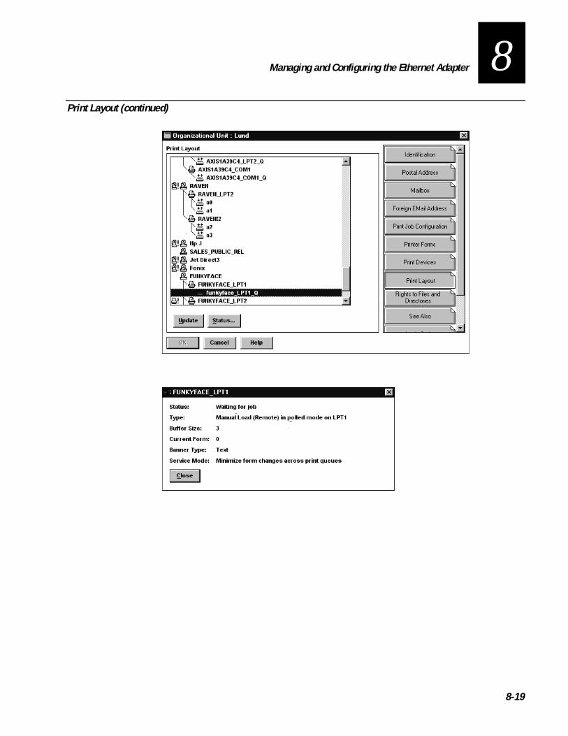
Managing and Configuring the Ethernet Adapter
8-19
8Print Layout (continued)


Updating the Software
9


Updating the Software
9-3
9This chapter explains how to update the software on your Ethernet adapter.
Obtaining Updated SoftwareYou can update the following software:
• AXIS NetPilot configuration software
• AXIS Print Monitor for Windows 95, 98, and NT
• AXIS Print Utility for Windows
• AXIS Print Utility for OS/2
• The Ethernet adapter software held in Flash Memory
• The axinstall script
• The AXIS MIB file
The Ethernet adapter’s software is stored in Flash Memory. This memory is provided by asilicon chip that, like any other ROM (read only memory) device, retains data contenteven after power is removed. However, Flash Memory is unique because it allows itsdata to be erased and rewritten. This ability means that you can install software updatesfor your Ethernet adapter as soon as they become available, without having to replaceany parts. The new software is simply loaded into the Ethernet adapter over thenetwork.
Contact your Intermec service representative to check if there have been any newreleases of the software. You should have your present version number ready tocompare against the latest software release.
Downloading the Software Over the InternetYou may want to check the Axis web site at www.axis.com, where you can downloadthe latest versions of the software utilities.
Downloading the Software Over Anonymous FTPFiles and information are also available through anonymous ftp: log into ftp.axis.comand go to the /pub/axis directory.
Updating the Flash MemoryYou can use three methods to update the Ethernet adapter’s flash memory:
• AXIS NetPilot
• FTP over the network on a TCP/IP network
• Parallel port

Intermec Ethernet Adapter User’s Manual
9-4
The preferred methods are described in this chapter.
Note: Updating instructions are also supplied with the software update.
Updating Using the AXIS NetPilotAn installation wizard is available to guide you through the necessary procedures.Simply click on the Upgrade icon of the AXIS NetPilot toolbar to display the UpgradeWizard menu. You need to put the firmware upgrade in the upgrade folder of AXISNetPilot.
After AXIS NetPilot finishes sending the firmware, wait about one minute before tryingto communicate with the Ethernet adapter.
Upgrading Over the Network Using FTPTo upgrade over the network using FTP, you will need the following:
• The file with the new software. The name of this file is in the form 540 .version ,for example 540.556 for software release 5.56. You may use any of theaforementioned methods to obtain the new file.
• The Ethernet adapter must also be installed on the network with TCP/IP. For help,see “Setting Up for TCP/IP” in Chapter 2.
To upgrade the Ethernet adapter
1. Log into the Ethernet adapter with the command ftp host_name wherehost_name is the name assigned in your system host table.
2. You will be prompted for a user id and password. Use the user id root , which hasthe default password pass (root is the user id with the highest priority).
3. Issue the command binary to change to binary transfer mode.
4. Issue the command put software_name flash where software_name is thename of the new software, such as 540.556 .
5. Wait for the Flash load to finish. This normally takes 1 to 4 minutes. The unit willthen automatically restart with the new software.
Note: Be careful not to interrupt the file transfer. If the transfer is interrupted, theEthernet adapter may have to be re-initialized by your dealer.
6. Log out using the command quit , bye , or exit depending on your FTP version.
Note: Should you encounter any problem that prevents a successful upgrade over yournetwork, it may become necessary to perform the flash loading operation via theparallel port, LPT1. In this instance, you are advised to contact Intermec.
Configuration Parameters
A

Configuration Parameters
A-3
AThis appendix provides an overview of the Ethernet adapter’s parameters anddescribes how they may be edited. A sample configuration file is also included.However, please note that because of recent print server software updates, somedifferences may exist between the parameters installed on your print server and thosedescribed in this appendix.
Changing the Configuration ParametersFor a complete description of the parameters, please refer to the AXIS Network PrintServer Technical Reference. Alternatively, you may want to access the Axis web site atwww.axis.com where you can download the latest technical information.
Using AXIS NetPilotThe configuration file stores all the parameter values, which you can edit via theProperty Pages of the AXIS NetPilot software. Each Property Page comprises an arrayof selection tabs that are appropriate to your operating environments. You can defineeach parameter using the relevant box.
You can also edit the parameters using the Parameter Editor, which is started fromwithin AXIS NetPilot.
After AXIS NetPilot sends the new parameters to the Ethernet adapter, wait about oneminute before trying to communicate with the Ethernet adapter.
For further information on the AXIS NetPilot, see Chapter 3, “Setting Up the EthernetAdapter for a NetWare Network.”
Using a Web BrowserIf your network supports TCP/IP, you may view and edit the Ethernet adapter’sconfiguration parameters using any standard Web browser.
Using FTPThe file transfer protocol (FTP) provides another alternative for changing the parametersettings.
Using FTP for UNIX, Windows, and OS/2 Workstations
1. Log in to the Ethernet adapter by typing the command:
ftp host_name
2. Enter root as user id and pass as password.
3. Upload the configuration file by typing get config .
4. Edit the file using your preferred text editor.

Intermec Ethernet Adapter User’s Manual
A-4
5. Download the configuration file by typing put config CONFIG .
Note: Specify the edited file name in block capitals. Otherwise, the edits are regardedas temporary and will be lost once the Ethernet adapter has been powered down.
Using FTP for MacintoshTo edit the configuration file from a Macintosh, you will need FTP support such asMacTCP, Fetch, or Anarchie. Once you have installed FTP support, use the procedurein the previous section to edit the configuration file.
Sample Configuration ParametersThe remainder of this appendix contains the complete Ethernet adapter’s configurationfile. The left-hand column shows the parameters and their default values as they appearin the configuration file, and the right-hand column contains brief descriptions of theparameters.
Most parameters will take effect in the print server for the next incoming print job afterbeing changed. However, those parameters marked (Requires Restart) will require theprint server to be restarted before the new parameter setting can take effect.
Please note that the password relating to parameters such as ROOT_PWD andPROS_PWD will only be shown when logged in as root.
--- GENERAL MENUNODE_ADDR. : 00 40 8C 10 00 86 Node AddressROOT_PWD. : pass Root PasswordUSERS. : User Authority and Printer AccessBASE URL. : WWW.AXIS.COM Default Base URL Address (‘+’ and Token
Ring models only)HP_JETADMIN. : YES (AUTO_SENSE, YES, NO) HP JetAdmin Support EnabledDEF_OUT. : PR1 (PR1, PR2, PR3, PR4, PR5,PR6, PR7, PR8, LPT1)
Internal Printout Destination
--- TCP/IP MENUTCP_ENB. : YES TCP/IP Protocol EnabledINT_ADDR. : 0 0 0 0 IP AddressDEF_ROUT. : 0 0 0 0 Default Router Address (0.0.0.0 for no
router)NET_MASK. : 0 0 0 0 Net Mask (e.g. 255.255.255.0 for class
C, 0.0.0.0 for auto-sense)PROS_PRT. : 35 PROS TCP Port NumberPROS_PWD. : netprinter PROS Protocol PasswordLPD_BANN. : NO LPD Banner Page Disabled

Configuration Parameters
A-5
ASample Configuration Parameters (continued)
DHCP_ENB. : YES DHCP Protocol EnabledBOOTP_ENB. : YES BOOTP Protocol EnabledRARP_ENB. : YES RARP Protocol EnabledWINS_ENB. : YES WINS Protocol EnabledWINS_ADDR1. : 0 0 0 0 The IP address of the primary WINS
serverWINS_ADDR2. : 0 0 0 0 The IP address of the secondary WINS
serverNBT_SCOPE_ID : Defines the NetBIOS scope to be used
with WINS name registrationRTN_OPT. : YES Reverse Telnet Options EnabledRTEL_PR1. : 0 PR1 Reverse Telnet TCP Port Number (0
for Disabled)RTEL_PR2. : 0 PR2 Reverse Telnet TCP Port Number (0
for Disabled)RTEL_PR3. : 0 PR3 Reverse Telnet TCP Port Number (0
for Disabled)RTEL_PR4. : 0 PR4 Reverse Telnet TCP Port Number (0
for Disabled)RTEL_PR5. : 0 PR5 Reverse Telnet TCP Port Number (0
for Disabled)RTEL_PR6. : 0 PR6 Reverse Telnet TCP Port Number (0
for Disabled)RTEL_PR7. : 0 PR7 Reverse Telnet TCP Port Number (0
for Disabled)RTEL_PR8. : 0 PR8 Reverse Telnet TCP Port Number (0
for Disabled)
--- SNMP MENUREAD_COM. : public Read-Only Community NameWRT_COM. : pass Read-Write Community NameTRAPADDR. : 0 0 0 0 SNMP Trap IP AddressTRAP_COM. : public SNMP Trap Community NameSYS_CONT. : System ContactSYS_NAME. : System NameSYS_LOC. : System LocationSNMP_AUT. : DISABLE(DISABLE, ENABLE) Authentication Failure TrapsTRAP_PRT. : DISABLE(DISABLE, ENABLE) Printer Traps
--- NETWARE MENUNETW_ENB. : YES NetWare Protocol EnabledPS_NAME. : AXIS100086 Print Server Name (100086 are the last
six digits of the serial number)JOB_CHECK_DELAY. : 5 Print Server queue polling interval

Intermec Ethernet Adapter User’s Manual
A-6
Sample Configuration Parameters (continued)
CONF_CHECK_DELAY. : 300 Interval between automaticconfiguration checks
FR_802_3. : YES IEEE 802.3 Frame Type EnabledFR_ETH_2. : YES Ethernet II Frame Type EnabledFR_802_2. : YES IEEE 802.2 Frame Type EnabledFR_SNAP. : YES SNAP Frame Type EnabledNCP_BURST_MODE. : YES NetWare Burst Mode Enabled(Requires
Restart)PSERVER_NDS.: File server & Name of print server
(including context)PSERVER_BINDERY1. : Bindery file server namePSERVER_BINDERY2. : Bindery file server namePSERVER_BINDERY3. : Bindery file server namePSERVER_BINDERY4. : Bindery file server namePSERVER_BINDERY5. : Bindery file server namePSERVER_BINDERY6. : Bindery file server namePSERVER_BINDERY7. : Bindery file server namePSERVER_BINDERY8. : Bindery file server namePSERVER_BINDERY9. : Bindery file server namePSERVER_BINDERY10. : Bindery file server namePSERVER_BINDERY11. : Bindery file server namePSERVER_BINDERY12. : Bindery file server namePSERVER_BINDERY13. : Bindery file server namePSERVER_BINDERY14. : Bindery file server namePSERVER_BINDERY15. : Bindery file server namePSERVER_BINDERY16. : Bindery file server nameNPRINTER1. : Print Server name. SlotNPRINTER2. : Print Server name. SlotNPRINTER3. : Print Server name. SlotNPRINTER4. : Print Server name. SlotNPRINTER5. : Print Server name. SlotNPRINTER6. : Print Server name. SlotNPRINTER7. : Print Server name. SlotNPRINTER8. : Print Server name. Slot
--- NetBIOS/NetBEUI MENULSLM_ENB. : YES LAN Server/LAN Manager Protocol EnabledNB_FR_TYPE. : FR_AUTO (FR_AUTO, FR_802_2,FR_DIX)
Frame Type(Requires Restart)
LPRINT_1. : AX100086.LP1 Printer 1 Name (100086 are the last sixcharacters of the serial number)
LLOGIC_1. : PR1 (PR1, PR2, PR3, PR4, PR5,PR6, PR7, PR8, LPT1)
Printer 1 Logical Printer
LPRINT_2. : Printer 2 NameLLOGIC_2. : PR2 (PR1, PR2, PR3, PR4, PR5,PR6, PR7, PR8, LPT1)
Printer 2 Logical Printer
LPRINT_3. : Printer 3 NameLLOGIC_3. : PR3 (PR1, PR2, PR3, PR4, PR5,PR6, PR7, PR8, LPT1)
Printer 3 Logical Printer
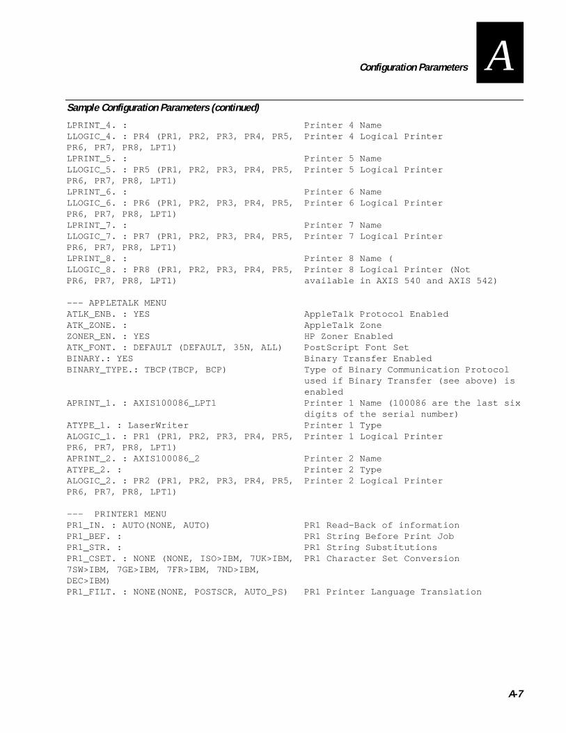
Configuration Parameters
A-7
ASample Configuration Parameters (continued)
LPRINT_4. : Printer 4 NameLLOGIC_4. : PR4 (PR1, PR2, PR3, PR4, PR5,PR6, PR7, PR8, LPT1)
Printer 4 Logical Printer
LPRINT_5. : Printer 5 NameLLOGIC_5. : PR5 (PR1, PR2, PR3, PR4, PR5,PR6, PR7, PR8, LPT1)
Printer 5 Logical Printer
LPRINT_6. : Printer 6 NameLLOGIC_6. : PR6 (PR1, PR2, PR3, PR4, PR5,PR6, PR7, PR8, LPT1)
Printer 6 Logical Printer
LPRINT_7. : Printer 7 NameLLOGIC_7. : PR7 (PR1, PR2, PR3, PR4, PR5,PR6, PR7, PR8, LPT1)
Printer 7 Logical Printer
LPRINT_8. : Printer 8 Name (LLOGIC_8. : PR8 (PR1, PR2, PR3, PR4, PR5,PR6, PR7, PR8, LPT1)
Printer 8 Logical Printer (Notavailable in AXIS 540 and AXIS 542)
--- APPLETALK MENUATLK_ENB. : YES AppleTalk Protocol EnabledATK_ZONE. : AppleTalk ZoneZONER_EN. : YES HP Zoner EnabledATK_FONT. : DEFAULT (DEFAULT, 35N, ALL) PostScript Font SetBINARY.: YES Binary Transfer EnabledBINARY_TYPE.: TBCP(TBCP, BCP) Type of Binary Communication Protocol
used if Binary Transfer (see above) isenabled
APRINT_1. : AXIS100086_LPT1 Printer 1 Name (100086 are the last sixdigits of the serial number)
ATYPE_1. : LaserWriter Printer 1 TypeALOGIC_1. : PR1 (PR1, PR2, PR3, PR4, PR5,PR6, PR7, PR8, LPT1)
Printer 1 Logical Printer
APRINT_2. : AXIS100086_2 Printer 2 NameATYPE_2. : Printer 2 TypeALOGIC_2. : PR2 (PR1, PR2, PR3, PR4, PR5,PR6, PR7, PR8, LPT1)
Printer 2 Logical Printer
--- PRINTER1 MENUPR1_IN. : AUTO(NONE, AUTO) PR1 Read-Back of informationPR1_BEF. : PR1 String Before Print JobPR1_STR. : PR1 String SubstitutionsPR1_CSET. : NONE (NONE, ISO>IBM, 7UK>IBM,7SW>IBM, 7GE>IBM, 7FR>IBM, 7ND>IBM,DEC>IBM)
PR1 Character Set Conversion
PR1_FILT. : NONE(NONE, POSTSCR, AUTO_PS) PR1 Printer Language Translation

Intermec Ethernet Adapter User’s Manual
A-8
Sample Configuration Parameters (continued)
PR1_AFT. : PR1 String After Print JobPR1_DUMP. : NO PR1 Hex Dump ModePR1_SIZE. : A4(A4, LETTER, LEGAL, EXECUT) PR1 PostScript Page SizePR1_ORNT. : PORTR (PORTR, LANDS, R_PORTR,R_LANDS)
PR1 PostScript Page Orientation
PR1_FORM. : 66 0 100 60 30 50 PR1 PostScript Page Format (MPL, MPP,CPI, LPI, LM, TM)
PR1_FONT. : PR1 PostScript Font (Courier when notspecified)
--- PRINTER2 MENUPR2_IN. : AUTO(NONE, AUTO) PR2 Read-Back of informationPR2_BEF. : PR2 String Before Print JobPR2_STR. : PR2 String SubstitutionsPR2_CSET. : NONE (NONE, ISO>IBM, 7UK>IBM,7SW>IBM, 7GE>IBM, 7FR>IBM, 7ND>IBM,DEC>IBM)
PR2 Character Set Conversion
PR2_FILT. : NONE(NONE, POSTSCR, AUTO_PS) PR2 Printer Language TranslationPR2_AFT. : PR2 String After Print JobPR2_DUMP. : NO PR2 Hex Dump ModePR2_SIZE. : A4(A4, LETTER, LEGAL, EXECUT) PR2 PostScript Page SizePR2_ORNT. : PORTR (PORTR, LANDS, R_PORTR,R_LANDS)
PR2 PostScript Page Orientation
PR2_FORM. : 66 0 100 60 30 50 PR2 PostScript Page Format (MPL, MPP,CPI, LPI, LM, TM)
PR2_FONT. : PR2 PostScript Font (Courier when notspecified)
--- PRINTER3 MENUPR3_IN. : AUTO(NONE, AUTO) PR3 Read-Back of informationPR3_BEF. : PR3 String Before Print JobPR3_STR. : PR3 String SubstitutionsPR3_CSET. : NONE (NONE, ISO>IBM, 7UK>IBM,7SW>IBM, 7GE>IBM, 7FR>IBM, 7ND>IBM,DEC>IBM)
PR3 Character Set Conversion
PR3_FILT. : NONE(NONE, POSTSCR, AUTO_PS) PR3 Printer Language TranslationPR3_AFT. : PR3 String After Print JobPR3_DUMP. : NO PR3 Hex Dump ModePR3_SIZE. : A4(A4, LETTER, LEGAL, EXECUT) PR3 PostScript Page SizePR3_ORNT. : PORTR(PORTR, LANDS, R_PORTR,R_LANDS)
PR3 PostScript Page Orientation
PR3_FORM. : 66 0 100 60 30 50 PR3 PostScript Page Format (MPL, MPP,CPI, LPI, LM, TM)
PR3_FONT. : PR3 PostScript Font (Courier when notspecified)
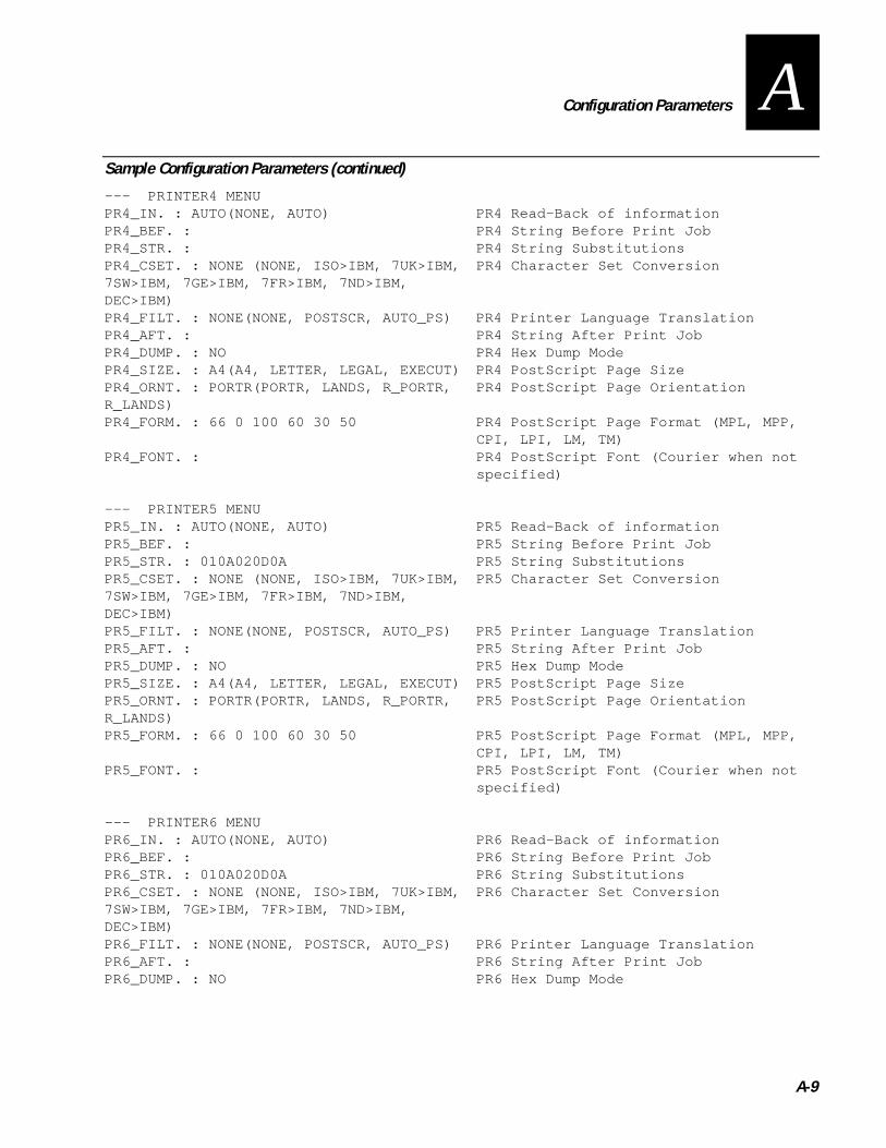
Configuration Parameters
A-9
ASample Configuration Parameters (continued)
--- PRINTER4 MENUPR4_IN. : AUTO(NONE, AUTO) PR4 Read-Back of informationPR4_BEF. : PR4 String Before Print JobPR4_STR. : PR4 String SubstitutionsPR4_CSET. : NONE (NONE, ISO>IBM, 7UK>IBM,7SW>IBM, 7GE>IBM, 7FR>IBM, 7ND>IBM,DEC>IBM)
PR4 Character Set Conversion
PR4_FILT. : NONE(NONE, POSTSCR, AUTO_PS) PR4 Printer Language TranslationPR4_AFT. : PR4 String After Print JobPR4_DUMP. : NO PR4 Hex Dump ModePR4_SIZE. : A4(A4, LETTER, LEGAL, EXECUT) PR4 PostScript Page SizePR4_ORNT. : PORTR(PORTR, LANDS, R_PORTR,R_LANDS)
PR4 PostScript Page Orientation
PR4_FORM. : 66 0 100 60 30 50 PR4 PostScript Page Format (MPL, MPP,CPI, LPI, LM, TM)
PR4_FONT. : PR4 PostScript Font (Courier when notspecified)
--- PRINTER5 MENUPR5_IN. : AUTO(NONE, AUTO) PR5 Read-Back of informationPR5_BEF. : PR5 String Before Print JobPR5_STR. : 010A020D0A PR5 String SubstitutionsPR5_CSET. : NONE (NONE, ISO>IBM, 7UK>IBM,7SW>IBM, 7GE>IBM, 7FR>IBM, 7ND>IBM,DEC>IBM)
PR5 Character Set Conversion
PR5_FILT. : NONE(NONE, POSTSCR, AUTO_PS) PR5 Printer Language TranslationPR5_AFT. : PR5 String After Print JobPR5_DUMP. : NO PR5 Hex Dump ModePR5_SIZE. : A4(A4, LETTER, LEGAL, EXECUT) PR5 PostScript Page SizePR5_ORNT. : PORTR(PORTR, LANDS, R_PORTR,R_LANDS)
PR5 PostScript Page Orientation
PR5_FORM. : 66 0 100 60 30 50 PR5 PostScript Page Format (MPL, MPP,CPI, LPI, LM, TM)
PR5_FONT. : PR5 PostScript Font (Courier when notspecified)
--- PRINTER6 MENUPR6_IN. : AUTO(NONE, AUTO) PR6 Read-Back of informationPR6_BEF. : PR6 String Before Print JobPR6_STR. : 010A020D0A PR6 String SubstitutionsPR6_CSET. : NONE (NONE, ISO>IBM, 7UK>IBM,7SW>IBM, 7GE>IBM, 7FR>IBM, 7ND>IBM,DEC>IBM)
PR6 Character Set Conversion
PR6_FILT. : NONE(NONE, POSTSCR, AUTO_PS) PR6 Printer Language TranslationPR6_AFT. : PR6 String After Print JobPR6_DUMP. : NO PR6 Hex Dump Mode
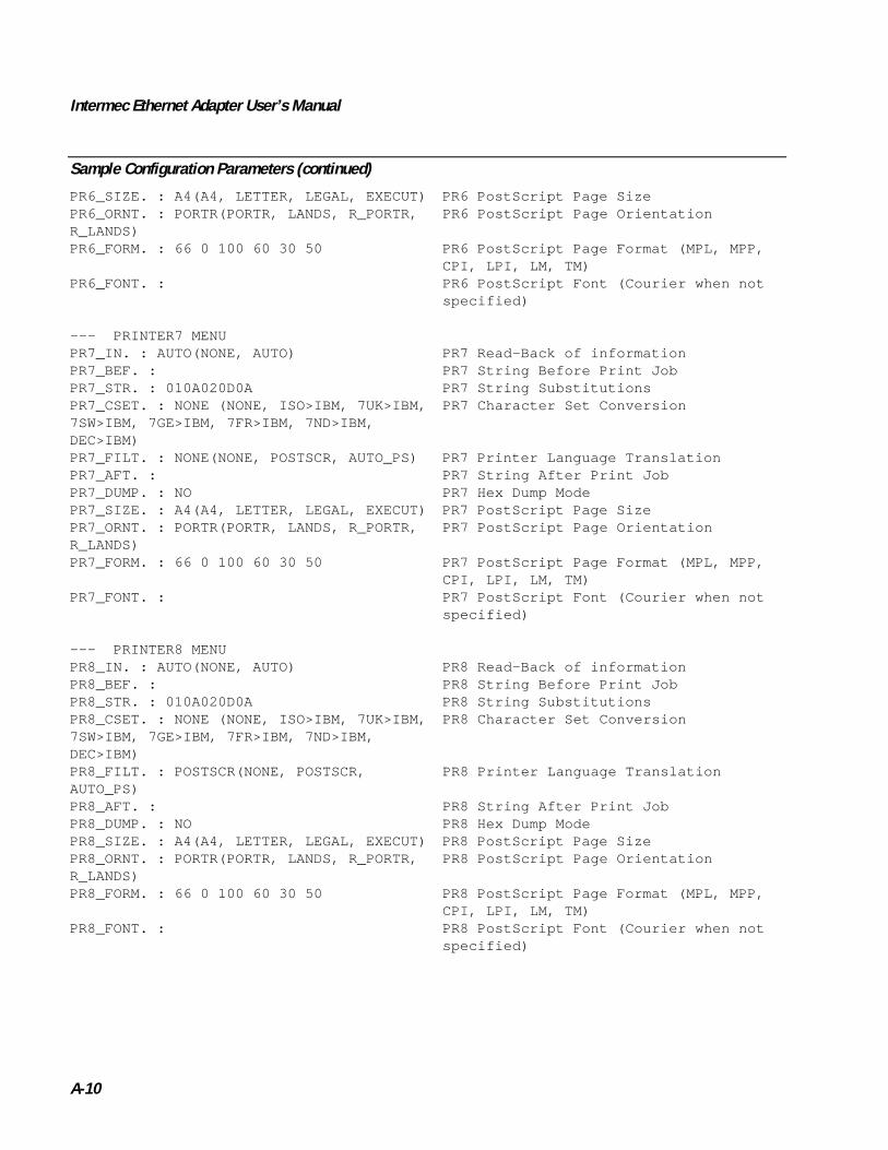
Intermec Ethernet Adapter User’s Manual
A-10
Sample Configuration Parameters (continued)
PR6_SIZE. : A4(A4, LETTER, LEGAL, EXECUT) PR6 PostScript Page SizePR6_ORNT. : PORTR(PORTR, LANDS, R_PORTR,R_LANDS)
PR6 PostScript Page Orientation
PR6_FORM. : 66 0 100 60 30 50 PR6 PostScript Page Format (MPL, MPP,CPI, LPI, LM, TM)
PR6_FONT. : PR6 PostScript Font (Courier when notspecified)
--- PRINTER7 MENUPR7_IN. : AUTO(NONE, AUTO) PR7 Read-Back of informationPR7_BEF. : PR7 String Before Print JobPR7_STR. : 010A020D0A PR7 String SubstitutionsPR7_CSET. : NONE (NONE, ISO>IBM, 7UK>IBM,7SW>IBM, 7GE>IBM, 7FR>IBM, 7ND>IBM,DEC>IBM)
PR7 Character Set Conversion
PR7_FILT. : NONE(NONE, POSTSCR, AUTO_PS) PR7 Printer Language TranslationPR7_AFT. : PR7 String After Print JobPR7_DUMP. : NO PR7 Hex Dump ModePR7_SIZE. : A4(A4, LETTER, LEGAL, EXECUT) PR7 PostScript Page SizePR7_ORNT. : PORTR(PORTR, LANDS, R_PORTR,R_LANDS)
PR7 PostScript Page Orientation
PR7_FORM. : 66 0 100 60 30 50 PR7 PostScript Page Format (MPL, MPP,CPI, LPI, LM, TM)
PR7_FONT. : PR7 PostScript Font (Courier when notspecified)
--- PRINTER8 MENUPR8_IN. : AUTO(NONE, AUTO) PR8 Read-Back of informationPR8_BEF. : PR8 String Before Print JobPR8_STR. : 010A020D0A PR8 String SubstitutionsPR8_CSET. : NONE (NONE, ISO>IBM, 7UK>IBM,7SW>IBM, 7GE>IBM, 7FR>IBM, 7ND>IBM,DEC>IBM)
PR8 Character Set Conversion
PR8_FILT. : POSTSCR(NONE, POSTSCR,AUTO_PS)
PR8 Printer Language Translation
PR8_AFT. : PR8 String After Print JobPR8_DUMP. : NO PR8 Hex Dump ModePR8_SIZE. : A4(A4, LETTER, LEGAL, EXECUT) PR8 PostScript Page SizePR8_ORNT. : PORTR(PORTR, LANDS, R_PORTR,R_LANDS)
PR8 PostScript Page Orientation
PR8_FORM. : 66 0 100 60 30 50 PR8 PostScript Page Format (MPL, MPP,CPI, LPI, LM, TM)
PR8_FONT. : PR8 PostScript Font (Courier when notspecified)

Configuration Parameters
A-11
ASample Configuration Parameters (continued)
--- OUTPUT MENUL1_CENTR. : HISPEED (IBM_PC, STNDRD, FAST,HISPEED)
LPT1 Centronics Interface Timing
L1_BSYTM. : 60 LPT1 Busy Status Time-Out. All statusreporting disabled if set to 0.
L1_MGM_INFO. : AUTO (DISABLE, AUTO) LPT1 Management Information


Technical Specifications
B

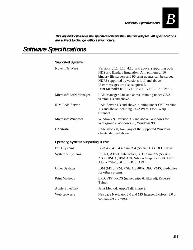
Technical Specifications
B-3
BThis appendix provides the specifications for the Ethernet adapter. All specificationsare subject to change without prior notice.
Software Specifications
Supported Systems
Novell NetWare Versions 3.11, 3.12, 4.10, and above, supporting bothNDS and Bindery Emulation. A maximum of 16bindery file servers and 96 print queues can be served.NDPS supported by versions 4.11 and above.User messages are also supported.Print Methods: RPRINTER/NPRINTER, PSERVER.
Microsoft LAN Manager LAN Manager 2.0c and above, running under OS/2version 1.3 and above.
IBM LAN Server LAN Server 1.3 and above, running under OS/2 version1.3 and above including OS/2 Warp, OS/2 WarpConnect.
Microsoft Windows Windows NT version 3.5 and above, Windows forWorkgroups, Windows 95, Windows 98.
LANtastic LANtastic 7.0, from any of the supported Windowsclients, defined above.
Operating Systems Supporting TCP/IP
BSD Systems BSD 4.2, 4.3, 4.4, SunOS4 (Solaris 1.X), DEC Ultrix.
System V Systems R3, R4, AT&T, Interactive, SCO, SunOS5 (Solaris2.X), HP-UX, IBM AIX, Silicon Graphics IRIX, DECAlpha OSF/1, BULL (BOS, AIX).
Other Systems IBM (MVS, VM, VSE, OS/400), DEC VMS, guidelinesfor other systems.
Print Methods LPD, FTP, PROS (named pipe & filtered), ReverseTelnet.
Apple EtherTalk Print Method: AppleTalk Phase 2.
Web browsers Netscape Navigator 3.0 and MS Internet Explorer 3.0 orcompatible browsers.

Intermec Ethernet Adapter User’s Manual
B-4
Supported Protocols
NetWare IPX, SAP, RIP, SPX, SNMP, NCP (extended withNDS), NLSP, DIAG.
Windows and OS/2 NetBIOS/NetBEUI or TCP/IP, WINS/NBNS.
LANtastic NetBIOS/NetBEUI.
TCP/IP LPD, FTP, Telnet, Reverse Telnet, PROS, BOOTP,ARP, RARP, DHCP, ICMP, IP, TCP, UDP, HTTP,SNMP, TFTP, SLP.
Apple EtherTalk AARP, ATP, DDP, NBP, PAP, RTMP, ZIP.
Network Management
SNMP-MIB II compliant (over UDP/IP and IPX), private enterprise MIB included.LAN Network Manager for OS/2. Print server status in NWAdmin/PCONSOLE.
Logical Connection
Running simultaneously any combination of the supported protocols. Use ofIEEE802.2, IEEE802.3, SNAP, and Ethernet II frame types simultaneously.
Security
UNIX Root password. User access list and printer access.
NetWare Encrypted passwords.
Physical Specifications
Hardware
• 32 bit RISC Controller, 1MB Flash memory. 256K RAM.
Attachments
• 10BaseT (Twisted Pair) Ethernet.
Logical Printers
The logical printer ports can be programmed to perform auto ASCII to PostScriptconversion, string before and after job, string substitution, alternative output andcharacter set conversion.

Technical Specifications
B-5
BParallel Printers
One IEEE 1284 compliant high-speed parallel port, 36-pin Centronics connector.Sustained throughput up to 400K per second using NetWare or LAN Server/LANManager. Bi-directional support for Apple, Reverse Telnet, PROS.
Front Panel
2 LED indicators: Power and Network.
Test button for information printouts.
Power Consumption
Maximum 170 mA at 12 VDC. (Type PS-A, 9 V, 300 mA). Power can optionally beprovided by the printer (Centronics pin 18: 5 VDC, 300 mA).
Dimensions for the External Ethernet Adapter
Height: 1.1 inches (2.7 cm)
Width: 2.2 inches (5.6 cm)
Depth: 4.7 inches (11.8 cm)
Weight: 0.26 lb (0.12 kg)
Environment
Temperature: 40°F to 105°F (5°C to 40°C)
Humidity: 10% to 95% noncondensing


Index
I


Index
I-3
IAabout this manual, xiiAccount button, 8-6account file
FTP, 8-13Telnet, 8-14
adding strings before and after print jobs, 7-8AIX (IBM RS/6000, BULL DPX 20), 7-4Anarchie, 6-3Apple EtherTalk, 6-3ARP
described, 2-8downloading the IP address, 2-9, 2-10
ASCII to PostScript, 7-9attachments, B-4axinstall
installing using FTP, 7-3suggested systems, 7-4
Axis client software, 1-6AXIS NetPilot, 2-5, 8-6 to 8-11
changing parameter values, 8-7, A-3Installation Wizard, 2-6installing on a PC or host, 2-5monitoring printers, 8-9Netware, using with, 3-4Printer Information window, 8-11property pages, 8-7starting, 8-7upgrading the adapter, 9-4using, 2-5window, 8-10
AXIS Print Monitor, 4-3installing on a PC or host, 2-5Windows 95 or 98, using with, 4-4Windows NT 3.5X, using with, 4-8Windows NT 4.0, using with, 4-6
AXIS Print Utilityfor OS/2, 5-3for Windows, 4-12
client/server printing, 4-15described, 4-13peer-to-peer printing, 4-14
installing on a PC or host, 2-5
Bbenefits, 1-6bi-directional printing, 7-10binary communication protocol (BCP), 6-3BOOTP
described, 2-8downloading the IP address, 2-11
BOS (BULL DPX 2), 7-4BSD, 7-6BSD systems, 2-10
CCentronics interface timing, 2-13character sets, converting in UNIX, 7-7Chooser window, 6-3client software, Axis, 1-6client/server printing, 4-4
described, 4-13setting up clients, 4-15using, 4-15
computer environments, compatible, 1-5configuration
button, 8-5file
changing, A-3 to A-4using FTP to edit, 8-12
parameterschanging, 8-7, A-3 to A-4Parameter List editor, using to edit, 8-8sample, A-4
Connect NetWare Print Queues window, 3-5connecting to your network, 2-3controlled access printers, installing, 3-3conventions for this manual, xiv
DData Line Print mode, 1-8debugging, 7-10DEC OSF/1 (Digital Equipment, Alpha), 7-4defaults
page format parameters, 7-9resetting, 1-9, 8-6, 8-15
DHCPdescribed, 2-8downloading the IP address, 2-9
dimensions, B-5DOS printing, 4-3downloading software
over FTP, 9-3over the Internet, 9-3
Eenvironmental conditions, B-5environments, computer, 1-5Ethernet adapter
connecting to your network, 2-3features and benefits, 1-6grouping, 8-10home page, 8-4illustrated, 1-4managing and configuring, 8-3parts and function, 1-5Web server, described, 1-6
ETRAX chip, 1-6external Ethernet adapter, See Ethernet adapterexternal power supply, 1-3
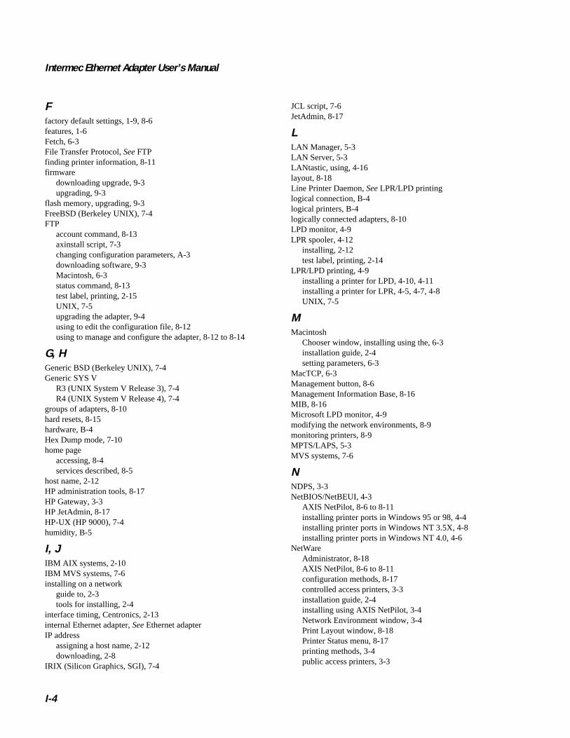
Intermec Ethernet Adapter User’s Manual
I-4
Ffactory default settings, 1-9, 8-6features, 1-6Fetch, 6-3File Transfer Protocol, See FTPfinding printer information, 8-11firmware
downloading upgrade, 9-3upgrading, 9-3
flash memory, upgrading, 9-3FreeBSD (Berkeley UNIX), 7-4FTP
account command, 8-13axinstall script, 7-3changing configuration parameters, A-3downloading software, 9-3Macintosh, 6-3status command, 8-13test label, printing, 2-15UNIX, 7-5upgrading the adapter, 9-4using to edit the configuration file, 8-12using to manage and configure the adapter, 8-12 to 8-14
G, HGeneric BSD (Berkeley UNIX), 7-4Generic SYS V
R3 (UNIX System V Release 3), 7-4R4 (UNIX System V Release 4), 7-4
groups of adapters, 8-10hard resets, 8-15hardware, B-4Hex Dump mode, 7-10home page
accessing, 8-4services described, 8-5
host name, 2-12HP administration tools, 8-17HP Gateway, 3-3HP JetAdmin, 8-17HP-UX (HP 9000), 7-4humidity, B-5
I, JIBM AIX systems, 2-10IBM MVS systems, 7-6installing on a network
guide to, 2-3tools for installing, 2-4
interface timing, Centronics, 2-13internal Ethernet adapter, See Ethernet adapterIP address
assigning a host name, 2-12downloading, 2-8
IRIX (Silicon Graphics, SGI), 7-4
JCL script, 7-6JetAdmin, 8-17
LLAN Manager, 5-3LAN Server, 5-3LANtastic, using, 4-16layout, 8-18Line Printer Daemon, See LPR/LPD printinglogical connection, B-4logical printers, B-4logically connected adapters, 8-10LPD monitor, 4-9LPR spooler, 4-12
installing, 2-12test label, printing, 2-14
LPR/LPD printing, 4-9installing a printer for LPD, 4-10, 4-11installing a printer for LPR, 4-5, 4-7, 4-8UNIX, 7-5
MMacintosh
Chooser window, installing using the, 6-3installation guide, 2-4setting parameters, 6-3
MacTCP, 6-3Management button, 8-6Management Information Base, 8-16MIB, 8-16Microsoft LPD monitor, 4-9modifying the network environments, 8-9monitoring printers, 8-9MPTS/LAPS, 5-3MVS systems, 7-6
NNDPS, 3-3NetBIOS/NetBEUI, 4-3
AXIS NetPilot, 8-6 to 8-11installing printer ports in Windows 95 or 98, 4-4installing printer ports in Windows NT 3.5X, 4-8installing printer ports in Windows NT 4.0, 4-6
NetWareAdministrator, 8-18AXIS NetPilot, 8-6 to 8-11configuration methods, 8-17controlled access printers, 3-3installation guide, 2-4installing using AXIS NetPilot, 3-4Network Environment window, 3-4Print Layout window, 8-18Printer Status menu, 8-17printing methods, 3-4public access printers, 3-3

Index
I-5
Inetwork
changing settings, 8-9compatible with the adapter, 1-5connecting to, 2-3environment window, 8-9installation guide, 2-3LED, 1-5management, B-4management system, 8-16privileges for TCP/IP, 2-7
NMS software, 8-16notification messages, 8-18Novell Distributed Print Services, See NDPS
O, Poperating systems supporting TCP/IP, B-3OS/2
AXIS Print Utility, 5-3installation guide, 2-4installing the Ethernet adapter, 5-3print queue
creating, 5-4sharing, 5-4
overview of the adapter, 1-3parallel port connector, 1-5parallel printers, B-5parameter list, 1-9Parameter List editor, 8-8parameter values
changing, 8-7, A-3 to A-4Parameter List editor, using to edit, 8-8sample, A-4setting in Macintosh, 6-3
peer-to-peer printing, 4-3described, 4-13using, 4-14
physical specifications, B-4 to B-5ping command, 2-10PostScript, converting ASCII to, 7-9power consumption, B-5Power LED, 1-5power supply, external, 1-3print
Data Line Print mode, 1-8layout window, 8-18quality label, 1-7queue
connecting in NetWare, 3-5creating in OS/2, 5-4sharing in OS/2, 5-4
server mode, 3-4printer
accessing information, 8-11compatible printers, 1-3connector, 1-5
printer (continued)groups, creating and editing, 8-9information window, 8-11monitoring, 8-9ports
installing with NetBIOS or NetBEUI, 4-4, 4-6, 4-8installing with TCP/IP, 4-5, 4-7, 4-8
status menu, 8-17property pages, 8-7PROS A and B, 7-5protocols, supported, B-4public access printer, installing, 3-3
R, SRARP
described, 2-8downloading the IP address, 2-10
reading back information, 7-10Remote Printer mode, 3-4resets, 8-15Reverse Telnet, 7-6safety summary, xiSCO UNIX (Santa Cruz Operation), 7-4security, B-4SETUP, 5-3shared printer, 4-10Simple Network Management Protocol (SNMP), 8-16soft resets, 8-15software
Axis client, 1-6specifications, B-3 to B-4updating, 9-3
specificationsphysical, B-4 to B-5software, B-3 to B-4
Status button, 8-6status file
FTP, 8-13Telnet, 8-15
status notification messages, 8-18string functions, 7-8substituting strings, 7-8SunOS 4 (SUN BSD, Solaris 1.x), 7-4SunOS 5 (SUN SYS V, Solaris 2.x), 7-4supported systems, B-3
Ttagged binary communication protocol (TBCP), 6-3TCP/IP
installing printer ports in Windows 95 or 98, 4-5installing printer ports in Windows NT 3.5X, 4-8installing printer ports in Windows NT 4.0, 4-7LPD monitor, 4-9LPR spooler, 2-12, 4-12network privileges, 2-7

Intermec Ethernet Adapter User’s Manual
I-6
TCP/IP (continued)operating systems supporting, B-3print methods, 7-4protocol stack, installing, 4-11setting up for, 2-7UNIX, 7-3UNIX print methods, 7-4 to 7-6with Windows, 4-3
Telnetaccount file, 8-14status file, 8-15using to manage and configure the adapter, 8-14 to 8-15
temperature, B-5terminology, xiiiTest button
described, 1-5using, 1-7
test labelFTP session, printing from, 2-15LPR spooler, printing from, 2-14
testing communications, 1-7TFTP
with BOOTP, 2-12with DHCP, 2-9
twisted pair (10BaseT) connection, 1-3, 2-3
U, WULTRIX (Digital Equipment, DEC), 7-4UNIX
customizing printing, 7-7 to 7-10debugging using Hex Dump mode, 7-10installation guide, 2-4TCP/IP print methods, 7-4 to 7-6
upgrading softwaredownloading over FTP, 9-3downloading over the Internet, 9-3
warranty information, xiWeb JetAdmin, 8-17Web pages, 8-4
described, 1-6editing configuration parameters, A-3
WindowsAXIS Print Monitor, 4-3
using with Windows 95 or 98, 4-4using with Windows NT 3.5X, 4-8using with Windows NT 4.0, 4-6
AXIS Print Utility for Windows, 4-12 to 4-15installation guide, 2-4LANtastic, using, 4-16LPD monitor with Windows NT 4.0, 4-10, 4-11LPR spooler, 2-12, 4-12printing environments, 4-3shared printer, 4-10
WINS, 2-9