interior rendering : exercise 10 - college of … · interior rendering : exercise 10 ... in this...
TRANSCRIPT
INTERIOR RENDERING : EXERCISE 10
College of DuPage Architecture 2220: Architectural Modeling 1
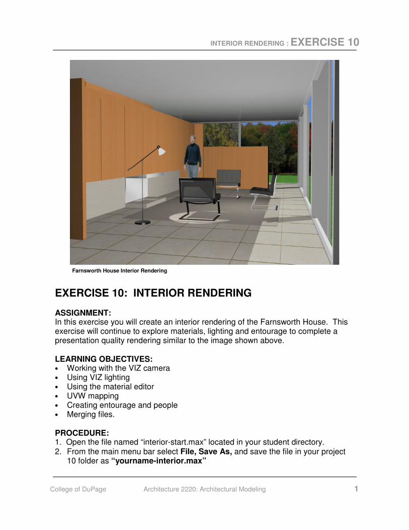
EXERCISE 10: INTERIOR RENDERING ASSIGNMENT: In this exercise you will create an interior rendering of the Farnsworth House. This exercise will continue to explore materials, lighting and entourage to complete a presentation quality rendering similar to the image shown above. LEARNING OBJECTIVES: • Working with the VIZ camera • Using VIZ lighting • Using the material editor • UVW mapping • Creating entourage and people • Merging files. PROCEDURE: 1. Open the file named “interior-start.max” located in your student directory. 2. From the main menu bar select File, Save As, and save the file in your project
10 folder as “yourname-interior.max”
Farnsworth House Interior Rendering
INTERIOR RENDERING : EXERCISE 10
College of DuPage Architecture 2220: Architectural Modeling 2
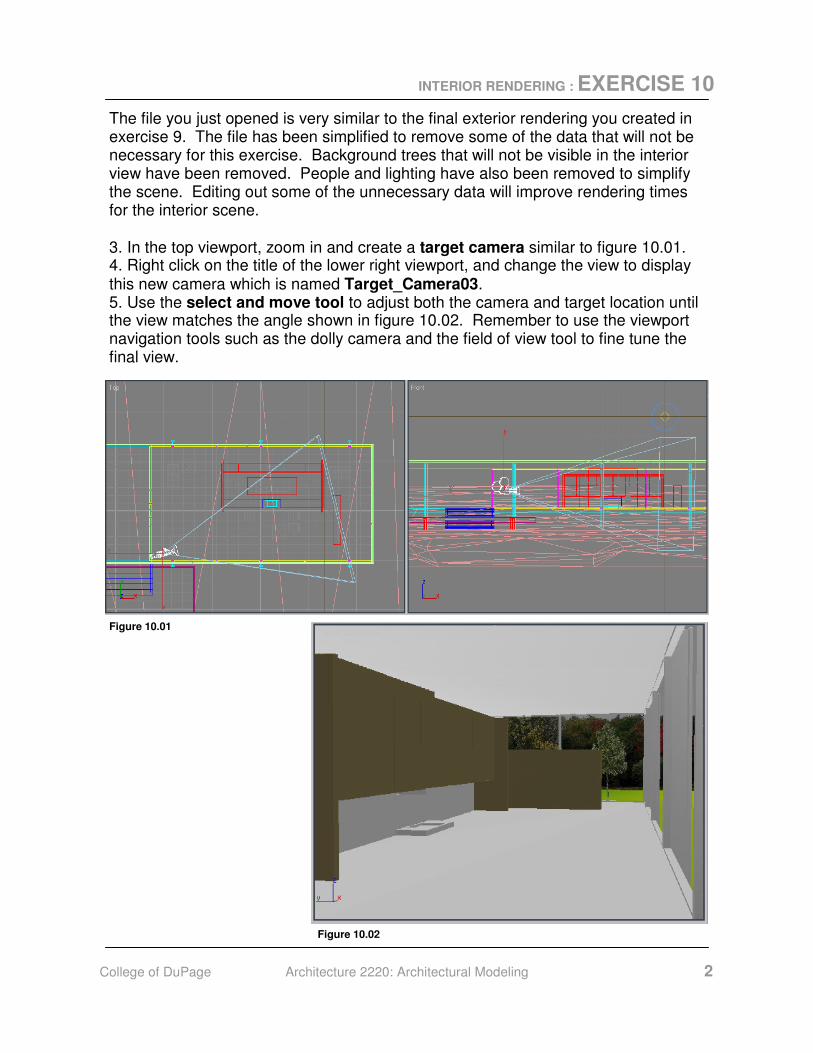
Figure 10.01
Figure 10.02
The file you just opened is very similar to the final exterior rendering you created in exercise 9. The file has been simplified to remove some of the data that will not be necessary for this exercise. Background trees that will not be visible in the interior view have been removed. People and lighting have also been removed to simplify the scene. Editing out some of the unnecessary data will improve rendering times for the interior scene. 3. In the top viewport, zoom in and create a target camera similar to figure 10.01. 4. Right click on the title of the lower right viewport, and change the view to display this new camera which is named Target_Camera03. 5. Use the select and move tool to adjust both the camera and target location until the view matches the angle shown in figure 10.02. Remember to use the viewport navigation tools such as the dolly camera and the field of view tool to fine tune the final view.
INTERIOR RENDERING : EXERCISE 10
College of DuPage Architecture 2220: Architectural Modeling 3
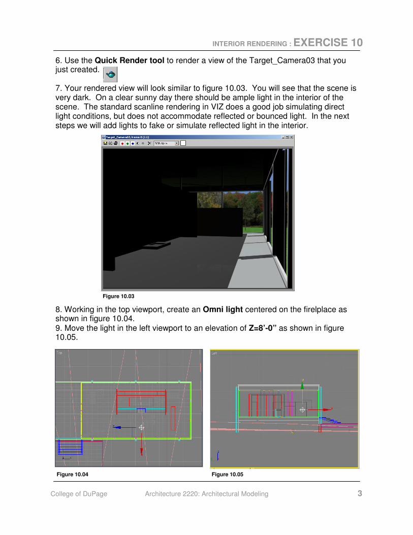
6. Use the Quick Render tool to render a view of the Target_Camera03 that you just created. 7. Your rendered view will look similar to figure 10.03. You will see that the scene is very dark. On a clear sunny day there should be ample light in the interior of the scene. The standard scanline rendering in VIZ does a good job simulating direct light conditions, but does not accommodate reflected or bounced light. In the next steps we will add lights to fake or simulate reflected light in the interior.
Figure 10.03
8. Working in the top viewport, create an Omni light centered on the firelplace as shown in figure 10.04. 9. Move the light in the left viewport to an elevation of Z=8’-0” as shown in figure 10.05.
Figure 10.04 Figure 10.05
INTERIOR RENDERING : EXERCISE 10
College of DuPage Architecture 2220: Architectural Modeling 4
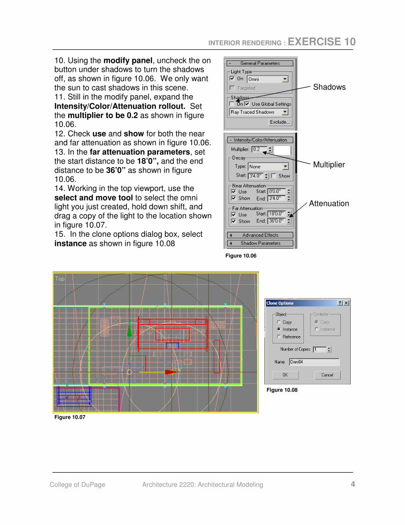
10. Using the modify panel, uncheck the on button under shadows to turn the shadows off, as shown in figure 10.06. We only want the sun to cast shadows in this scene. 11. Still in the modify panel, expand the Intensity/Color/Attenuation rollout. Set the multiplier to be 0.2 as shown in figure 10.06. 12. Check use and show for both the near and far attenuation as shown in figure 10.06. 13. In the far attenuation parameters, set the start distance to be 18’0”, and the end distance to be 36’0” as shown in figure 10.06. 14. Working in the top viewport, use the select and move tool to select the omni light you just created, hold down shift, and drag a copy of the light to the location shown in figure 10.07. 15. In the clone options dialog box, select instance as shown in figure 10.08
Shadows
Multiplier
Attenuation
Figure 10.06
Figure 10.07
Figure 10.08
INTERIOR RENDERING : EXERCISE 10
College of DuPage Architecture 2220: Architectural Modeling 5
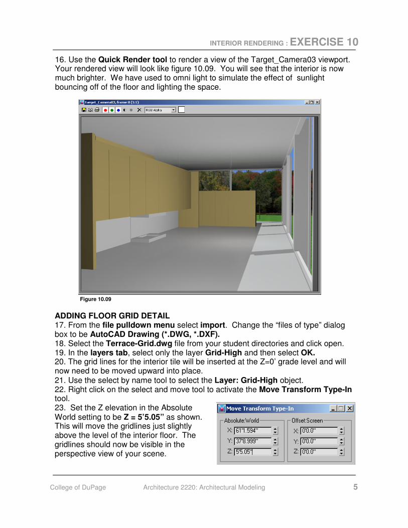
16. Use the Quick Render tool to render a view of the Target_Camera03 viewport. Your rendered view will look like figure 10.09. You will see that the interior is now much brighter. We have used to omni light to simulate the effect of sunlight bouncing off of the floor and lighting the space.
Figure 10.09
ADDING FLOOR GRID DETAIL 17. From the file pulldown menu select import. Change the “files of type” dialog box to be AutoCAD Drawing (*.DWG, *.DXF). 18. Select the Terrace-Grid.dwg file from your student directories and click open. 19. In the layers tab, select only the layer Grid-High and then select OK. 20. The grid lines for the interior tile will be inserted at the Z=0’ grade level and will now need to be moved upward into place. 21. Use the select by name tool to select the Layer: Grid-High object. 22. Right click on the select and move tool to activate the Move Transform Type-In tool. 23. Set the Z elevation in the Absolute World setting to be Z = 5’5.05” as shown. This will move the gridlines just slightly above the level of the interior floor. The gridlines should now be visible in the perspective view of your scene.
INTERIOR RENDERING : EXERCISE 10
College of DuPage Architecture 2220: Architectural Modeling 6
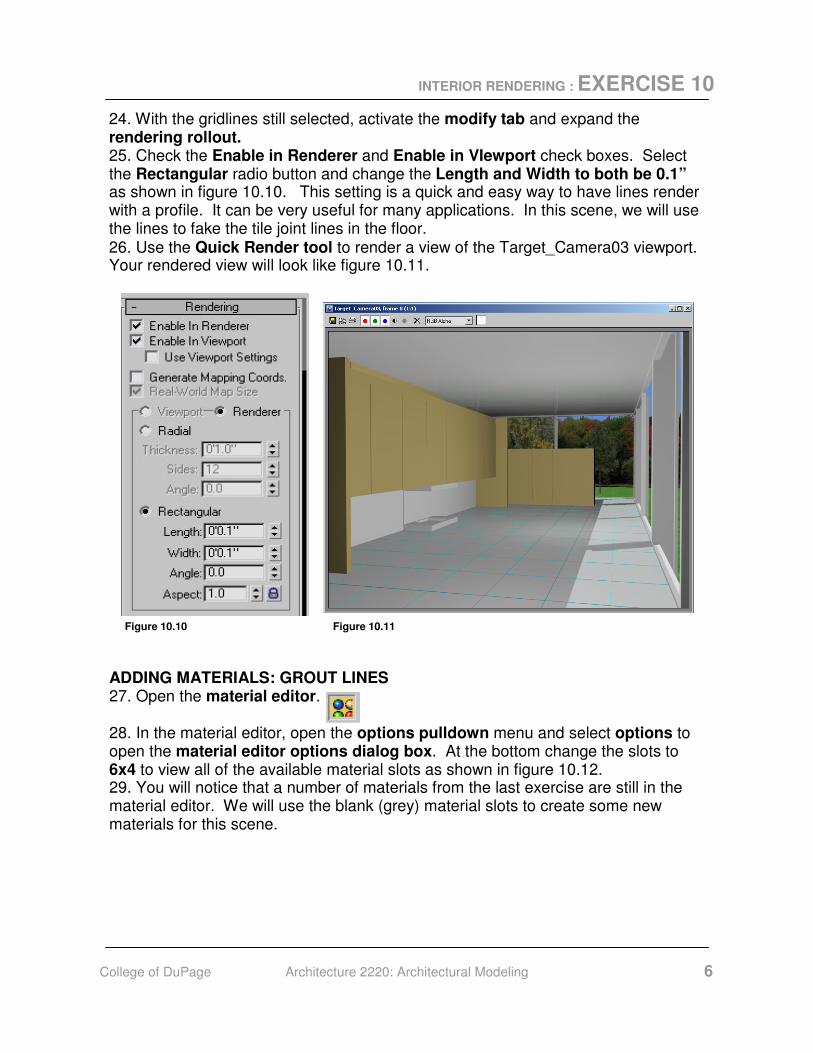
24. With the gridlines still selected, activate the modify tab and expand the rendering rollout. 25. Check the Enable in Renderer and Enable in VIewport check boxes. Select the Rectangular radio button and change the Length and Width to both be 0.1” as shown in figure 10.10. This setting is a quick and easy way to have lines render with a profile. It can be very useful for many applications. In this scene, we will use the lines to fake the tile joint lines in the floor. 26. Use the Quick Render tool to render a view of the Target_Camera03 viewport. Your rendered view will look like figure 10.11.
Figure 10.10 Figure 10.11
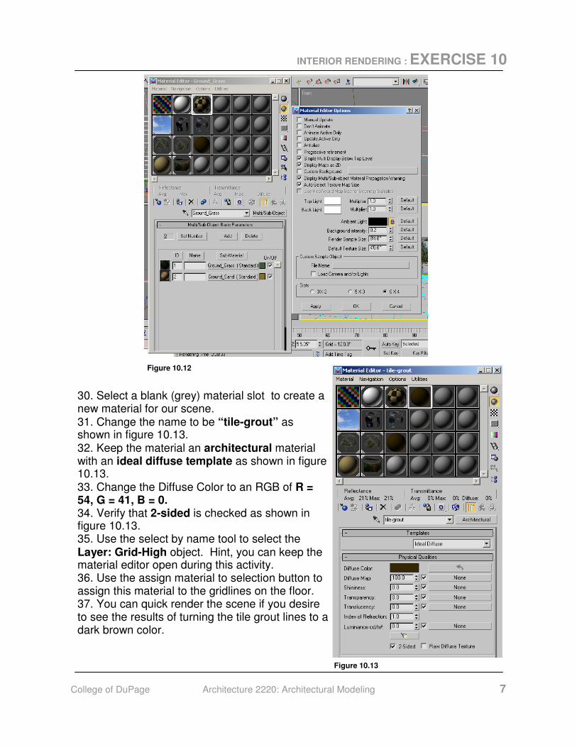
ADDING MATERIALS: GROUT LINES 27. Open the material editor. 28. In the material editor, open the options pulldown menu and select options to open the material editor options dialog box. At the bottom change the slots to 6x4 to view all of the available material slots as shown in figure 10.12. 29. You will notice that a number of materials from the last exercise are still in the material editor. We will use the blank (grey) material slots to create some new materials for this scene.
INTERIOR RENDERING : EXERCISE 10
College of DuPage Architecture 2220: Architectural Modeling 7
30. Select a blank (grey) material slot to create a new material for our scene. 31. Change the name to be “tile-grout” as shown in figure 10.13. 32. Keep the material an architectural material with an ideal diffuse template as shown in figure 10.13. 33. Change the Diffuse Color to an RGB of R = 54, G = 41, B = 0. 34. Verify that 2-sided is checked as shown in figure 10.13. 35. Use the select by name tool to select the Layer: Grid-High object. Hint, you can keep the material editor open during this activity. 36. Use the assign material to selection button to assign this material to the gridlines on the floor. 37. You can quick render the scene if you desire to see the results of turning the tile grout lines to a dark brown color.
Figure 10.12
Figure 10.13

INTERIOR RENDERING : EXERCISE 10
College of DuPage Architecture 2220: Architectural Modeling 8
ADDING MATERIALS: TRAVERTINE 38. Select a blank (grey) material slot to create a new material for our scene. 39. Use the Get Material button to open the Material Map Browser. 40. Select the Browse From: Material Library radio button, and then scroll down and find the Stones_Travertn (standard) material. 41. Double click the material name to bring it into your material editor in the active material slot. 42. Close the Material / Map Browser. 43. Use the select by name tool to select the house-travertine object. 44. Use the Assign Material to Selection button to assign the material. 45. With the house-travertine object still selected. Open the modify tab in the command panel. 46. Apply a UVW Map Modifier from the Modifier List. 47. Select the Box radio button. 48. Uncheck Real-World Map Size 49. Enter 15 for the U, V, and W tiles as shown in figure 10.14. 50. Use the Quick Render tool to render a view of the Target_Camera03 viewport. Your rendered view will look like figure 10.15.
Figure 10.14 Figure 10.15
INTERIOR RENDERING : EXERCISE 10
College of DuPage Architecture 2220: Architectural Modeling 9
51. We will use the same procedure as before to assign the travertine material to the core object.
52. Use the Select by Name tool to select the Layer:core-travetine object. 53. Use the Assign Material to Selection button to assign the travertine material to
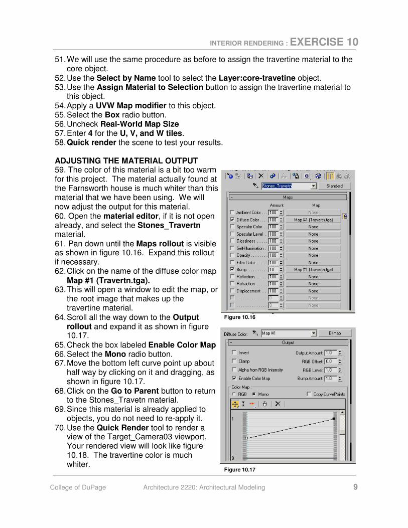
this object. 54. Apply a UVW Map modifier to this object. 55. Select the Box radio button. 56. Uncheck Real-World Map Size 57. Enter 4 for the U, V, and W tiles. 58. Quick render the scene to test your results. ADJUSTING THE MATERIAL OUTPUT 59. The color of this material is a bit too warm for this project. The material actually found at the Farnsworth house is much whiter than this material that we have been using. We will now adjust the output for this material. 60. Open the material editor, if it is not open already, and select the Stones_Travertn material. 61. Pan down until the Maps rollout is visible as shown in figure 10.16. Expand this rollout if necessary. 62. Click on the name of the diffuse color map
Map #1 (Travertn.tga). 63. This will open a window to edit the map, or
the root image that makes up the travertine material.
64. Scroll all the way down to the Output rollout and expand it as shown in figure 10.17.
65. Check the box labeled Enable Color Map 66. Select the Mono radio button. 67. Move the bottom left curve point up about
half way by clicking on it and dragging, as shown in figure 10.17.
68. Click on the Go to Parent button to return to the Stones_Travetn material.
69. Since this material is already applied to objects, you do not need to re-apply it.
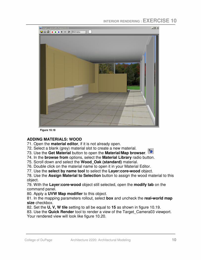
70. Use the Quick Render tool to render a view of the Target_Camera03 viewport. Your rendered view will look like figure 10.18. The travertine color is much whiter.
Figure 10.16
Figure 10.17
INTERIOR RENDERING : EXERCISE 10
College of DuPage Architecture 2220: Architectural Modeling 10
Figure 10.18
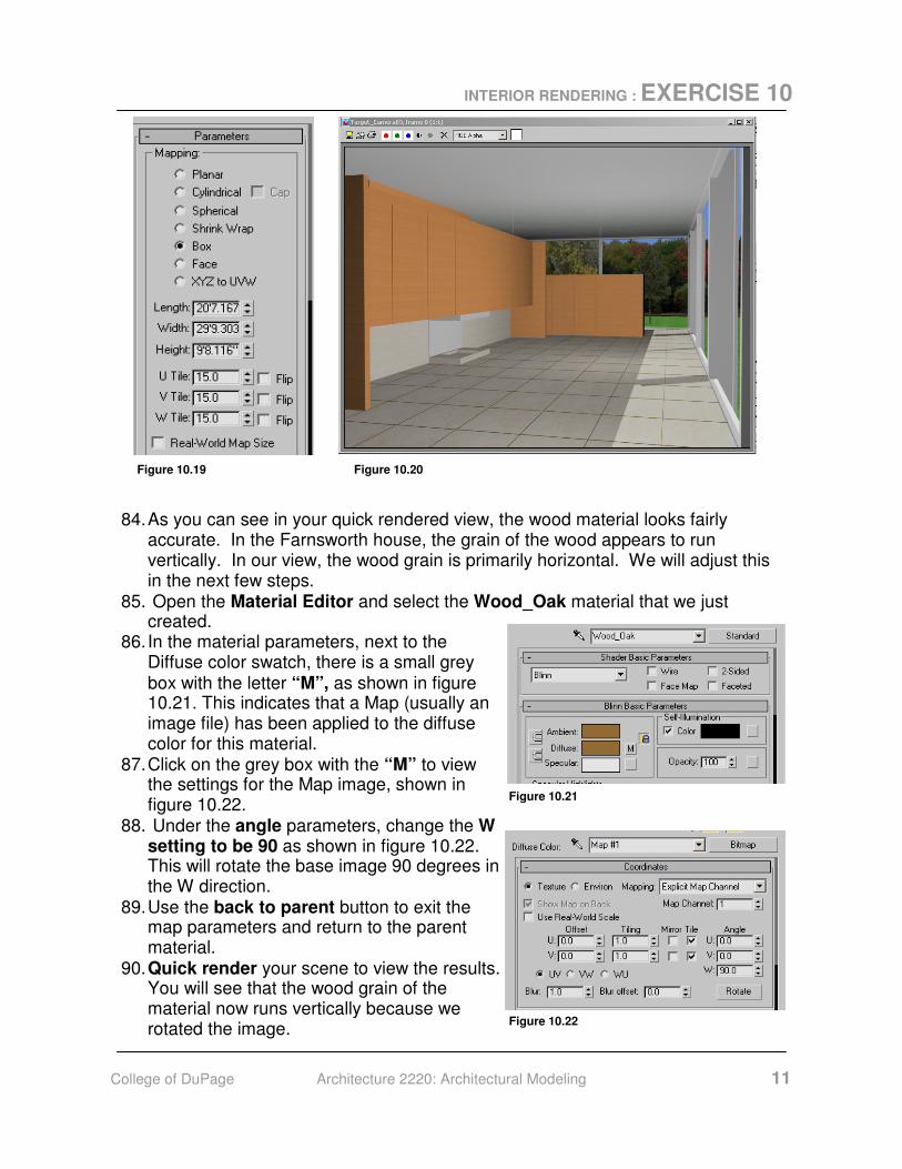
ADDING MATERIALS: WOOD 71. Open the material editor, if it is not already open. 72. Select a blank (grey) material slot to create a new material. 73. Use the Get Material button to open the Material/Map browser. 74. In the browse from options, select the Material Library radio button. 75. Scroll down and select the Wood_Oak (standard) material. 76. Double click on the material name to open it in your Material Editor. 77. Use the select by name tool to select the Layer:core-wood object. 78. Use the Assign Material to Selection button to assign the wood material to this object. 79. With the Layer:core-wood object still selected, open the modify tab on the command panel. 80. Apply a UVW Map modifier to this object. 81. In the mapping parameters rollout, select box and uncheck the real-world map size checkbox. 82. Set the U, V, W tile setting to all be equal to 15 as shown in figure 10.19. 83. Use the Quick Render tool to render a view of the Target_Camera03 viewport. Your rendered view will look like figure 10.20.
INTERIOR RENDERING : EXERCISE 10
College of DuPage Architecture 2220: Architectural Modeling 11
Figure 10.19 Figure 10.20
84. As you can see in your quick rendered view, the wood material looks fairly accurate. In the Farnsworth house, the grain of the wood appears to run vertically. In our view, the wood grain is primarily horizontal. We will adjust this in the next few steps.
85. Open the Material Editor and select the Wood_Oak material that we just created.
86. In the material parameters, next to the Diffuse color swatch, there is a small grey box with the letter “M”, as shown in figure 10.21. This indicates that a Map (usually an image file) has been applied to the diffuse color for this material.
87. Click on the grey box with the “M” to view the settings for the Map image, shown in figure 10.22.
88. Under the angle parameters, change the W setting to be 90 as shown in figure 10.22. This will rotate the base image 90 degrees in the W direction.
89. Use the back to parent button to exit the map parameters and return to the parent material.
90. Quick render your scene to view the results. You will see that the wood grain of the material now runs vertically because we rotated the image.
Figure 10.21
Figure 10.22
INTERIOR RENDERING : EXERCISE 10
College of DuPage Architecture 2220: Architectural Modeling 12
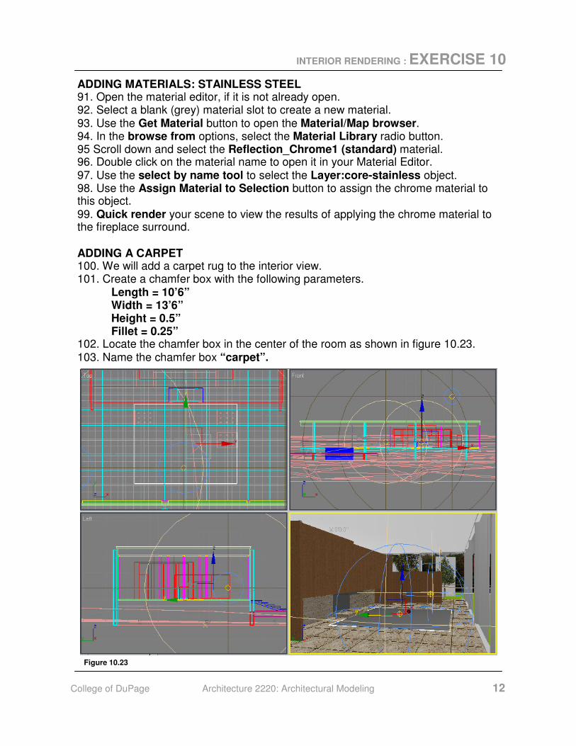
ADDING MATERIALS: STAINLESS STEEL 91. Open the material editor, if it is not already open. 92. Select a blank (grey) material slot to create a new material. 93. Use the Get Material button to open the Material/Map browser. 94. In the browse from options, select the Material Library radio button. 95 Scroll down and select the Reflection_Chrome1 (standard) material. 96. Double click on the material name to open it in your Material Editor. 97. Use the select by name tool to select the Layer:core-stainless object. 98. Use the Assign Material to Selection button to assign the chrome material to this object. 99. Quick render your scene to view the results of applying the chrome material to the fireplace surround. ADDING A CARPET 100. We will add a carpet rug to the interior view. 101. Create a chamfer box with the following parameters. Length = 10’6” Width = 13’6” Height = 0.5” Fillet = 0.25” 102. Locate the chamfer box in the center of the room as shown in figure 10.23. 103. Name the chamfer box “carpet”.
Figure 10.23
INTERIOR RENDERING : EXERCISE 10
College of DuPage Architecture 2220: Architectural Modeling 13
ADDING MATERIALS TO THE CARPET 104. Open the material editor, and select a blank (grey) material to create the carpet material. 105. Use the get material button to open the material/map browser. 106. Select the Fabric_Tan_Carpet (standard) material and double click to import it into your material editor. 107.Be sure that the chamfer box you just created is still selected, and apply the
carpet material to the chamfer box named “carpet”. 108. Use the modify tab to apply a UVW map modifier to the carpet. 109.As with the previous sections of this exercise, select box, uncheck the “real-
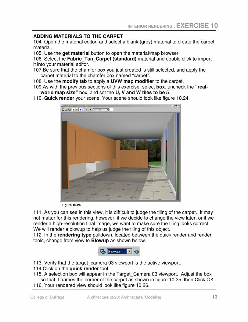
world map size” box, and set the U, V and W tiles to be 5. 110. Quick render your scene. Your scene should look like figure 10.24.
Figure 10.24
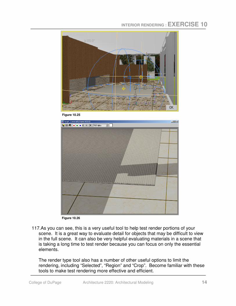
111. As you can see in this view, it is difficult to judge the tiling of the carpet. It may not matter for this rendering, however, if we decide to change the view later, or if we render a high-resolution final image, we want to make sure the tiling looks correct. We will render a blowup to help us judge the tiling of this object. 112. In the rendering type pulldown, located between the quick render and render tools, change from view to Blowup as shown below. 113. Verify that the target_camera 03 viewport is the active viewport. 114.Click on the quick render tool. 115. A selection box will appear in the Target_Camera 03 viewport. Adjust the box
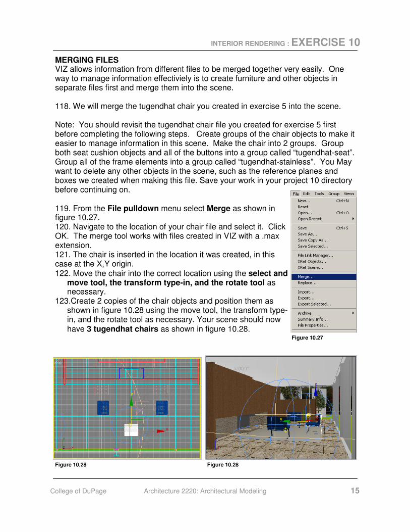
so that it frames the corner of the carpet as shown in figure 10.25, then Click OK. 116. Your rendered view should look like figure 10.26.
INTERIOR RENDERING : EXERCISE 10
College of DuPage Architecture 2220: Architectural Modeling 14
Figure 10.25
Figure 10.26
117.As you can see, this is a very useful tool to help test render portions of your scene. It is a great way to evaluate detail for objects that may be difficult to view in the full scene. It can also be very helpful evaluating materials in a scene that is taking a long time to test render because you can focus on only the essential elements.
The render type tool also has a number of other useful options to limit the rendering, including “Selected”, “Region” and “Crop”. Become familiar with these tools to make test rendering more effective and efficient.
INTERIOR RENDERING : EXERCISE 10
College of DuPage Architecture 2220: Architectural Modeling 15
MERGING FILES VIZ allows information from different files to be merged together very easily. One way to manage information effectiviely is to create furniture and other objects in separate files first and merge them into the scene. 118. We will merge the tugendhat chair you created in exercise 5 into the scene. Note: You should revisit the tugendhat chair file you created for exercise 5 first before completing the following steps. Create groups of the chair objects to make it easier to manage information in this scene. Make the chair into 2 groups. Group both seat cushion objects and all of the buttons into a group called “tugendhat-seat”. Group all of the frame elements into a group called “tugendhat-stainless”. You May want to delete any other objects in the scene, such as the reference planes and boxes we created when making this file. Save your work in your project 10 directory before continuing on. 119. From the File pulldown menu select Merge as shown in figure 10.27. 120. Navigate to the location of your chair file and select it. Click OK. The merge tool works with files created in VIZ with a .max extension. 121. The chair is inserted in the location it was created, in this case at the X,Y origin. 122. Move the chair into the correct location using the select and
move tool, the transform type-in, and the rotate tool as necessary.
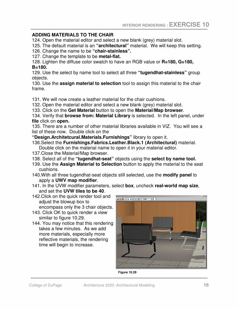
123.Create 2 copies of the chair objects and position them as shown in figure 10.28 using the move tool, the transform type-in, and the rotate tool as necessary. Your scene should now have 3 tugendhat chairs as shown in figure 10.28.
Figure 10.27
Figure 10.28 Figure 10.28
INTERIOR RENDERING : EXERCISE 10
College of DuPage Architecture 2220: Architectural Modeling 16
ADDING MATERIALS TO THE CHAIR 124. Open the material editor and select a new blank (grey) material slot. 125. The default material is an “architectural” material. We will keep this setting. 126. Change the name to be “chair-stainless”. 127. Change the template to be metal-flat. 128. Lighten the diffuse color swatch to have an RGB value or R=180, G=180, B=180. 129. Use the select by name tool to select all three “tugendhat-stainless” group objects. 130. Use the assign material to selection tool to assign this material to the chair frame. 131. We will now create a leather material for the chair cushions. 132. Open the material editor and select a new blank (grey) material slot. 133. Click on the Get Material button to open the Material/Map browser. 134. Verify that browse from: Material Library is selected. In the left panel, under file click on open. 135. There are a number of other material libraries available in VIZ. You will see a list of these now. Double click on the “Design.Architetcural.Materials.Furnishings” library to open it. 136.Select the Furnishings.Fabrics.Leather.Black.1 (Architectural) material.
Double click on the material name to open it in your material editor. 137.Close the Material/Map browser. 138. Select all of the “tugendhat-seat” objects using the select by name tool. 139. Use the Assign Material to Selection button to apply the material to the seat
cushions. 140.With all three tugendhat-seat objects still selected, use the modify panel to
apply a UWV map modifier. 141. In the UVW modifier parameters, select box, uncheck real-world map size,
and set the UVW tiles to be 40. 142.Click on the quick render tool and
adjust the blowup box to encompass only the 3 chair objects.
143. Click OK to quick render a view similar to figure 10.29.
144. You may notice that this rendering takes a few minutes. As we add more materials, especially more reflective materials, the rendering time will begin to increase.
Figure 10.29
INTERIOR RENDERING : EXERCISE 10
College of DuPage Architecture 2220: Architectural Modeling 17
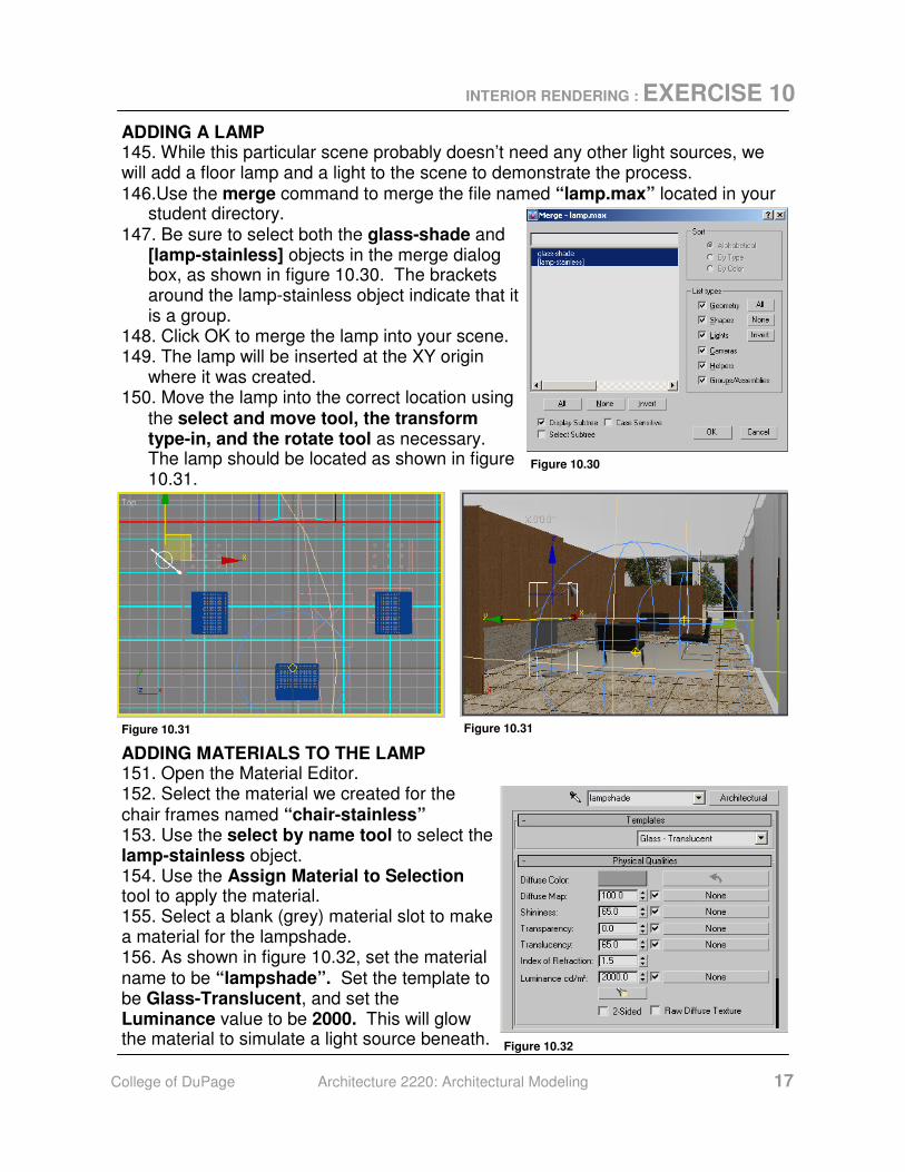
ADDING A LAMP 145. While this particular scene probably doesn’t need any other light sources, we will add a floor lamp and a light to the scene to demonstrate the process. 146.Use the merge command to merge the file named “lamp.max” located in your
student directory. 147. Be sure to select both the glass-shade and
[lamp-stainless] objects in the merge dialog box, as shown in figure 10.30. The brackets around the lamp-stainless object indicate that it is a group.
148. Click OK to merge the lamp into your scene. 149. The lamp will be inserted at the XY origin
where it was created. 150. Move the lamp into the correct location using
the select and move tool, the transform type-in, and the rotate tool as necessary. The lamp should be located as shown in figure 10.31.
Figure 10.30
Figure 10.31 Figure 10.31
ADDING MATERIALS TO THE LAMP 151. Open the Material Editor. 152. Select the material we created for the chair frames named “chair-stainless” 153. Use the select by name tool to select the lamp-stainless object. 154. Use the Assign Material to Selection tool to apply the material. 155. Select a blank (grey) material slot to make a material for the lampshade. 156. As shown in figure 10.32, set the material name to be “lampshade”. Set the template to be Glass-Translucent, and set the Luminance value to be 2000. This will glow the material to simulate a light source beneath. Figure 10.32
INTERIOR RENDERING : EXERCISE 10
College of DuPage Architecture 2220: Architectural Modeling 18
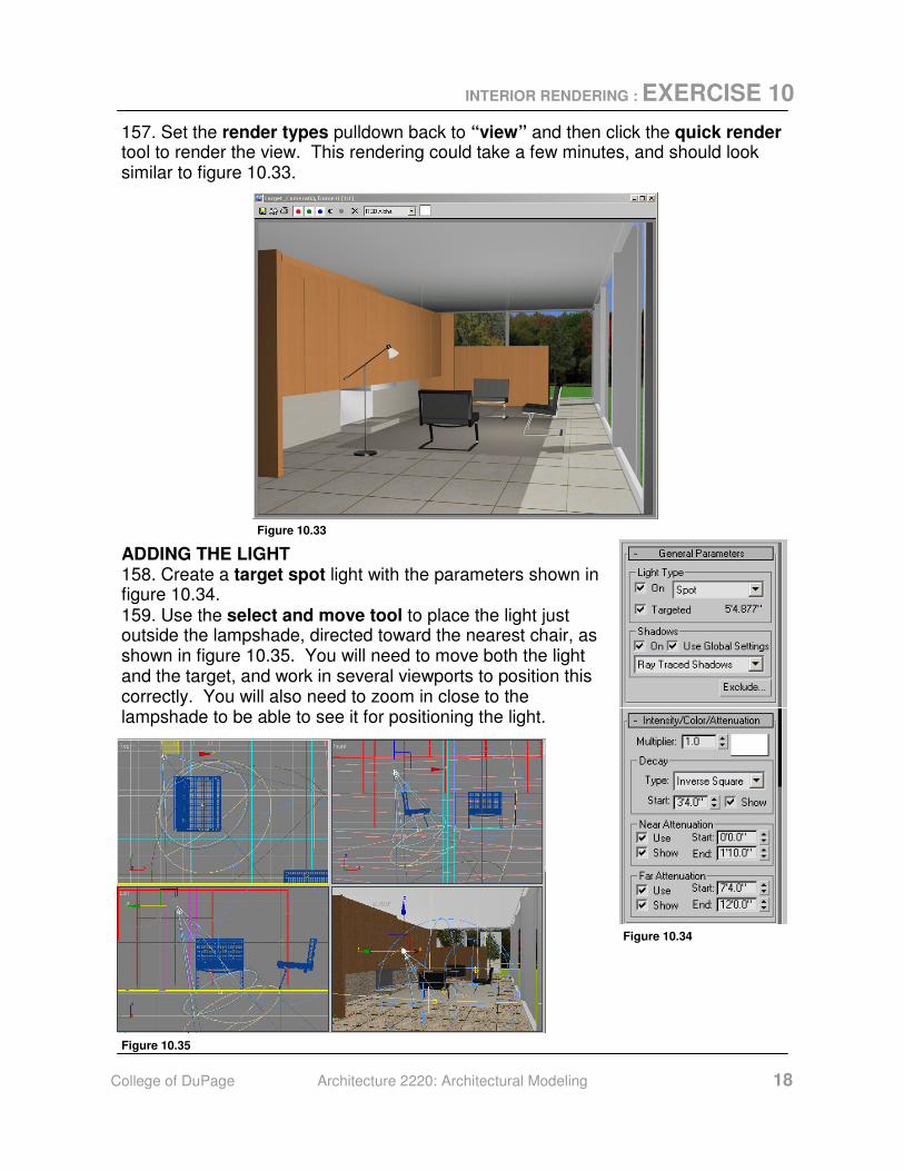
157. Set the render types pulldown back to “view” and then click the quick render tool to render the view. This rendering could take a few minutes, and should look similar to figure 10.33.
Figure 10.33
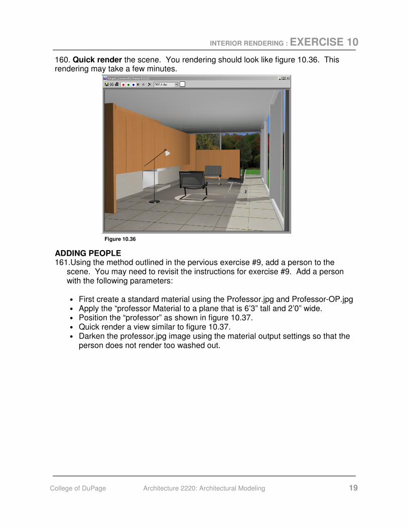
ADDING THE LIGHT 158. Create a target spot light with the parameters shown in figure 10.34. 159. Use the select and move tool to place the light just outside the lampshade, directed toward the nearest chair, as shown in figure 10.35. You will need to move both the light and the target, and work in several viewports to position this correctly. You will also need to zoom in close to the lampshade to be able to see it for positioning the light.
Figure 10.34
Figure 10.35
INTERIOR RENDERING : EXERCISE 10
College of DuPage Architecture 2220: Architectural Modeling 19
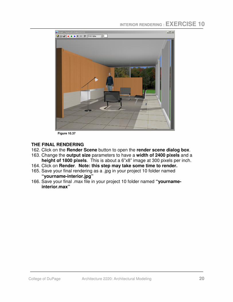
160. Quick render the scene. You rendering should look like figure 10.36. This rendering may take a few minutes.
Figure 10.36
ADDING PEOPLE 161.Using the method outlined in the pervious exercise #9, add a person to the
scene. You may need to revisit the instructions for exercise #9. Add a person with the following parameters:
• First create a standard material using the Professor.jpg and Professor-OP.jpg • Apply the “professor Material to a plane that is 6’3” tall and 2’0” wide. • Position the “professor” as shown in figure 10.37. • Quick render a view similar to figure 10.37. • Darken the professor.jpg image using the material output settings so that the
person does not render too washed out.
INTERIOR RENDERING : EXERCISE 10
College of DuPage Architecture 2220: Architectural Modeling 20
Figure 10.37
THE FINAL RENDERING 162. Click on the Render Scene button to open the render scene dialog box. 163. Change the output size parameters to have a width of 2400 pixels and a
height of 1800 pixels. This is about a 6”x8” image at 300 pixels per inch. 164. Click on Render. Note: this step may take some time to render. 165. Save your final rendering as a .jpg in your project 10 folder named
“yourname-interior.jpg” 166. Save your final .max file in your project 10 folder named “yourname-
interior.max”