interim iala guidelines on universal · pdf file1.2.1 imo performance standard ... 6.1.19...
TRANSCRIPT

1
DRAF T
INTERIM
IALA GUIDELINES
ON
UNIVERSAL SHIPBORNEAUTOMATIC IDENTIFICATION
SYSTEM
(AIS)
AIS 10/5/3AIS GuidelinesOctober 31, 2001

2

3
Table of Contents
Foreword...................................................................................................................................................8PREFACE.................................................................................................................................................9
Introduction..........................................................................................................................................9Purpose.................................................................................................................................................9Background ........................................................................................................................................10The International AIS Approval Route. .............................................................................................10International Maritime Organisation (IMO) Performance Standard. .................................................10International Electrotechnical Commission (IEC) and the Universal AIS Standard..........................12International Maritime Organisation (IMO) Carriage Requirement...................................................12Non SOLAS Convention Ships..........................................................................................................12Administration/Competant Authority Shore Installations..................................................................13Universal AIS Key Dates. ..................................................................................................................13Recommendations, Standards and Guidelines. ..................................................................................13
PART 1 OPERATIONAL ASPECTS OF AIS .....................................................................................14OPERATIONAL AND FUNCTIONAL REQUIREMENTS.................................................................15
1.1 General Description..................................................................................................................151.2 Mandatory Requirements..........................................................................................................15
1.2.1 IMO Performance Standard ............................................................................................151.2.2 Functional Requirements ................................................................................................161.2.3 IEC Test Standard ...........................................................................................................17
1.3 SOLAS Carriage Requirements................................................................................................181.4 Non-SOLAS Vessels ................................................................................................................191.5 Class A and B Shipborne Mobile Equipment ...........................................................................191.6 Inland Waterways .....................................................................................................................191.7 Aids to Navigation....................................................................................................................20
INFORMATION TRANSFER AND COMMUNICATIONS................................................................212.1 Data Transfer with AIS.............................................................................................................21
2.1.1 VHF Data Link (VDL) Capacity.....................................................................................222.2 Required Update Rates .............................................................................................................232.3 Display requirements ................................................................................................................242.4 Shipborne Installations .............................................................................................................242.5 Communications Requirements................................................................................................25
2.5.1 Radio Frequency Allocations ..........................................................................................252.5.2 Channel Management......................................................................................................26
2.6 Long Range Mode ....................................................................................................................272.7 Reporting format.......................................................................................................................27
2.7.1 Requirements ..................................................................................................................28AIS MESSAGES ....................................................................................................................................30
3.1 Message Types and Formats.....................................................................................................303.2 Standard Message Formats .......................................................................................................32
3.2.1 Position Report (Messages 1,2 or 3) ...............................................................................323.2.2 Base Station Report.........................................................................................................333.2.3 Static and Voyage Related Data......................................................................................353.2.4 Extended Static and Voyage Related Data......................................................................383.2.5 Ship Dimensions and Reference for Position..................................................................383.2.6 Binary Messages .............................................................................................................393.2.7 Short Safety Related Messages .......................................................................................39
3.3 Non Standard Messages............................................................................................................393.3.1 SAR Aircraft Position Report .........................................................................................393.3.2 DGNSS Broadcast Message............................................................................................403.3.3 Aid to Navigation Message .............................................................................................41
3.4 International Application Identifiers (IAIs) ..............................................................................443.4.1 Binary Messages and Functional Identifiers ...................................................................443.4.2 VTS Targets ....................................................................................................................463.4.3 International Function Message 17 (IFM 17) - Ship Waypoints/Route Plan ..................473.4.4 IFM 18 -Advice of VTS Waypoints/Route Plan .............................................................483.4.5 IFM 19 - Extended Ship Static and Voyage Related Data ..............................................49

4
3.4.6 IFM 40 - Number of Persons Onboard............................................................................50USING AIS SUPPLIED INFORMATION ............................................................................................51
4.1 BASIC OPERATION PROCEDURES ....................................................................................514.2 OPERATION DURING THE VOYAGE.................................................................................51
4.2.1 Activation........................................................................................................................524.2.2 Integrity Check................................................................................................................52
4.3 OPERATION IN A VTS AREA OR TSS................................................................................524.4 OPERATION IN A COASTAL AREA, SHIP REPORTING SYSTEM (SRS) AREA OREXCLUSIVE ECONOMIC ZONE (EEZ).........................................................................................534.5 POTENTIAL OF AIS IN COLLISION AVOIDANCE ...........................................................53
Risk of Collision............................................................................................................................544.5.2 Limitation of radar performance .....................................................................................544.5.3 Display of AIS Target Information .................................................................................574.5.4 Definitions.......................................................................................................................58
4.6 Operational requirements..........................................................................................................584.7 Presentation of information ......................................................................................................584.8 Processing of information.........................................................................................................604.9 Human Interface .......................................................................................................................61
OPERATION IN THE SHIP - SHIP MODE..........................................................................................63INFORMATION DISSEMINATION ....................................................................................................64
6.1 Presentation of AIS Information...............................................................................................646.1.1 Symbology ......................................................................................................................646.1.2 Displayed on Radar .........................................................................................................646.1.3 Displayed on ECDIS.......................................................................................................646.1.4 Dedicated Graphic Display .............................................................................................646.1.5 Integrated Navigation Systems........................................................................................646.1.6 Use of AIS Information...................................................................................................646.1.7 Navigation Warnings ......................................................................................................646.1.8 Meteorological Warnings................................................................................................646.1.9 Shipping Information ......................................................................................................646.1.10 Onboard Operation..........................................................................................................646.1.11 Interfaces. ........................................................................................................................646.1.12 ECDIS .............................................................................................................................646.1.13 Radar ...............................................................................................................................656.1.14 Independent display ........................................................................................................656.1.15 Gyro ................................................................................................................................656.1.16 Rate of turn......................................................................................................................656.1.17 Pitch and roll indicate......................................................................................................656.1.18 VDR ................................................................................................................................656.1.19 Speed log.........................................................................................................................656.1.20 GNSS/DGNSS ................................................................................................................65
PILOTAGE.............................................................................................................................................667.1 OVERVIEW.............................................................................................................................667.2 SILENT VTS............................................................................................................................667.3 SHORE TO VESSEL AIS SERVICES ....................................................................................667.4 POSSIBLE FUTURE USE OF AIS IN PILOTED WATERS .................................................667.5 PORTABLE PILOT PACK......................................................................................................678.1 BENEFITS OF AIS ..................................................................................................................70
8.1.1 Automatic Vessel Identification......................................................................................708.1.2 Improved Vessel Tracking ..............................................................................................718.1.3 Electronic transfer of sailing plan information................................................................728.1.4 Electronic transfer of safety messages. ...........................................................................728.1.5 Automatic indication of Voyage Related Information (cargoes, dangerous goods, etc) .728.1.6 Impact on VHF communications ....................................................................................738.1.7 Archiving data.................................................................................................................738.1.8 System redundancy .........................................................................................................738.1.9 Potential for interaction within regional AIS network ....................................................738.1.10 Improved SAR management ...........................................................................................73
8.2 INSTALLATION OF AIS INTO A VTS - ISSUES TO BE CONSIDERED..........................738.2.1 Number/location of base stations/repeaters.....................................................................73

5
8.2.2 Interoperability with adjacent VTS.................................................................................738.2.3 Availability of VHF Communication channels. ..............................................................738.2.4 Availability of national/regional/local DGNSS corrections............................................74
8.3 OTHER ISSUES TO BE TAKEN INTO CONSIDERATION ................................................748.3.1 Integration of AIS into existing radar based systems......................................................748.3.2 Use of electronic charts ...................................................................................................748.3.3 Choice of VTS Symbols..................................................................................................75
8.4 AIS AND AIDS TO NAVIGATION (AtoN)...........................................................................758.5 AIS FOR METEOROLOGICAL AND HYDROLOGICAL INFORMATION ......................768.6 PERSONNEL AND TRAINING .............................................................................................778.7 SHORT TERM ACTION BY VTS AUTHORITIES...............................................................778.8 Cautionary Note........................................................................................................................77
PART 2 TECHNICAL ASPECTS OF AIS ..........................................................................................78DESCRIPTION OF SYSTEM ARCHITECTURE OF THE AIS ..........................................................79
9.1 Introduction to the Technical Part of the IALA AIS Guidelines ..............................................799.2 System Architecture .................................................................................................................80
9.2.1 The AIS - a system designed using functional layers......................................................809.2.2 The special features of the AIS's "Wireless Propagation Layer" and its impact on thedesign of the AIS layer stack.........................................................................................................839.2.3 Grouping of AIS-related services and mapping them to the OSI layers .........................85
9.3 Mapping of layers to concrete devices and entities ..................................................................879.3.1 Actual AIS devices..........................................................................................................879.3.2 AIS Shore Network.........................................................................................................879.3.3 AIS-based VTS applications ...........................................................................................88
BASIC AIS SERVICES (BAS) ..............................................................................................................8910.1 Introduction..........................................................................................................................8910.2 List of basic AIS services ....................................................................................................8910.3 Structure of service descriptions ..........................................................................................92
Service Overview....................................................................................................................................92CHANNEL MANAGEMENT................................................................................................................94
11.1 Overview of chapter layout..................................................................................................9411.2 Introduction and fundamental concepts ..............................................................................94
11.2.1 Reasons for Channel Management..................................................................................9411.2.2 Parameters subject to channel management and their default settings............................9511.2.3 The definition of a region and its transitional zone.........................................................9611.2.4 A Region's relationship to the high seas (or default) region............................................9811.2.5 Two Regions' relationship including the High Seas Region ...........................................9911.2.6 IMO requires maximum extent of automated channel management.............................10011.2.7 Overview on means for automatic and manual channel management ..........................10011.2.8 Channel management as a privilege and as a responsibility for competent authorities.101
11.3 Channel management commands to a Class A shipborne mobile AIS station...................10111.4 Behaviour of a shipborne mobile AIS station entering or moving in a channel managementscheme 103
11.4.1 Description of mobile AIS station operation in the "two-channel transitional operatingmode" 10311.4.2 Operation of a mobile AIS station moving between and among three regions .............10511.4.3 Single-channel operation...............................................................................................107
11.5 Requirements and recommendations for competent authorities with regard to channelmanagement .....................................................................................................................................107
11.5.1 Fundamental layout rules for when planning regions ...................................................10711.5.2 Channel management by automatic means, i. e. by base stations .................................11011.5.3 Change of regional operating settings over time...........................................................110
11.6 Duplex Repeaters...............................................................................................................11111.7 Future work to be added at a later date ..............................................................................112
SHIPBORNE MOBILE AIS STATIONS ............................................................................................11312.1 Introduction........................................................................................................................11312.2 Definitions of AIS stations.................................................................................................11312.3 Common Features for all shipborne mobile AIS stations ..................................................11312.4 Specific issues for Class A Shipborne Mobile AIS stations ..............................................114
12.4.1 Functional Block Diagram ............................................................................................114

6
Presentation Interface Description...............................................................................................11512.4.3 Built-in-Integrity-Test (BIIT)........................................................................................11812.4.4 Minimum Keyboard and Display..................................................................................120
12.5 Specific issues for Class B Shipborne Mobile AIS stations...............................................12112.5.1 Operation of Class B shipborne mobile stations ...........................................................12212.5.2 User interface ................................................................................................................12212.5.3 Deviating functions compared with Class A stations....................................................122
12.6 Class A-derivatives ............................................................................................................12312.6.1 Presentation interface ....................................................................................................12312.6.2 Deviating functions compared with Class A stations....................................................12312.6.3 Pilot/Auxiliary port .......................................................................................................125
AIS BASE STATION...........................................................................................................................126AIDS TO NAVIGATION AIS STATION ...........................................................................................127
14.1 Introduction........................................................................................................................12714.2 AIS on Floating Aids to Navigation ..................................................................................12714.3 AIS on Fixed Aids to Navigation.......................................................................................12714.4 Ais oN Offshore structures ................................................................................................12714.5 Radar Reference Target .....................................................................................................12814.6 Virtual AIS Aids to Navigation targets..............................................................................12814.7 Virtual AtoN ......................................................................................................................12814.8 AIS AtoN STATION.........................................................................................................12814.9 AtoN Broadcast messages..................................................................................................12914.10 Methods of broadcasting AtoN AIS Messages ..................................................................12914.11 Types of Aid to Navigation................................................................................................13014.12 Name of AtoN....................................................................................................................13014.13 Off Position Indicator ........................................................................................................13114.14 Type of Position Fixing Device .........................................................................................13114.15 Dimensions of AtoN ..........................................................................................................132Use of Eight Data Bits for Local/Regional Use ...............................................................................13314.17 Virtual/Pseudo AtoN Target Flag ......................................................................................133
SAR AIRCRAFT AIS STATION.........................................................................................................13415.1 Scope .................................................................................................................................13415.2 Certification .......................................................................................................................134
15.2.1 Input/Output ..................................................................................................................13415.2.2 Identity ..........................................................................................................................13415.2.3 Aircraft pilot interface...................................................................................................13515.2.4 Rescue coordination centre communication..................................................................13515.2.5 Channel management ....................................................................................................135
CONSIDERATIONS FOR PLANNING OF AIS COVERAGE..........................................................13616.1 RF Coverage Area .............................................................................................................13616.2 Coverage Performance.......................................................................................................13616.3 Coverage Verification Recommendations .........................................................................13616.4 Planning criteria for an AIS land-based infrastructure.......................................................13616.5 Operational Coverage Area of a Base Station....................................................................137
16.5.1 Operation of non-synchronized mobile stations within the coverage area of a basestation (hidden user). ...................................................................................................................13716.5.2 Operation of mobile stations when the operational channel is overloaded: ..................137
16.6 Options for the basic architecture of AIS base stations. ....................................................13816.6.1 Adjustment of coverage range to traffic volume...........................................................13816.6.2 Use of passive, receive-only base stations ....................................................................13816.6.3 Using multiple base stations for a single coverage area................................................13816.6.4 Control of the transmission mode of mobile stations by base stations..........................13816.6.5 Base stations in combination with duplex repeaters to support the self-organizing ofmobile stations.............................................................................................................................13916.6.6 Coverage areas arbitrarily defined by a cellular operational network...........................139
16.7 Joint operation of several base stations..............................................................................13916.7.1 Coverage of large areas by base stations with long range. ............................................13916.7.2 Coverage of large areas by several base stations with large ranges subdivided intosectors. 13916.7.3 Coverage of large areas by several short-range base stations .......................................140

7
16.7.4 Coverage of large areas by long-range base stations and several short-range, passivebase stations.................................................................................................................................14016.7.5 Multiple coverage of coverage areas of base stations ...................................................14016.7.6 Increase of coverage areas of base stations by means of simplex repeaters..................140
16.8 Networks............................................................................................................................14016.9 Concluding Remarks..........................................................................................................140
CONFIGURATION MANAGEMENT OF AIS SHORE INFRASTRUCTURE ................................14217.1 General...............................................................................................................................142
PROCESSING OF AIS DATA FROM MULTIPLE BASE/MULTIPLE REPEATER STATIONENVIRONMENT AS IT AFFECTS THE VDL...................................................................................143
18.1 General...............................................................................................................................143NETWORKING ON SHORE SIDE USING TELECOMMUNICATIONS NETWORK ...................144AIS Shore Side Network Functionality.................................................................................................144
19.1 Introduction........................................................................................................................14419.2 Network functionality ........................................................................................................14419.3 Routing of information ......................................................................................................14419.4 Functional Structure...........................................................................................................145
19.4.1 Basic structure...............................................................................................................14519.4.2 Multiple base stations connected to multiple shore facilities. .......................................147
19.5 Communication links .........................................................................................................14719.6 Security ..............................................................................................................................14719.7 Other applications using the AIS network .........................................................................14719.8 Multiple networks ..............................................................................................................148
LONG RANGE APPLICATIONS .......................................................................................................14920.1. Architecture .......................................................................................................................14920.1 Messages between the AIS and the long-range communication system............................150
20.1.1 Interrogation of the AIS ................................................................................................15020.1.2 Reply of the AIS ...........................................................................................................151
20.2 Data exchange over the long-range communication system..............................................15220.2.1 Requirements ................................................................................................................15220.2.2 Functional design ..........................................................................................................152
EXAMPLE OF A PROCURMENT CONTRACT ...............................................................................157BIBLIOGRAPHY.................................................................................................................................158

8
Foreword
IALA's Role in the AIS Standards Development
International Association of Aids to Navigation and Lighthouse Authorities (IALA)has been the primary organisation sponsoring and co-ordinating the development ofthe Universal Shipborne Automatic Identification System (AIS) station. In 1996, theVTS and Radionavigation Committees of IALA prepared the draft recommendationthat, with further refinement within IMO NAV, became the basis for the IMOPerformance Standard on AIS.
In October 1997, at the request of several emerging AIS equipment manufacturers,IALA hosted a working group of manufacturers and maritime administrations to agreeon a standard technology for AIS stations. The group, which was formally designatedthe IALA AIS Working Group, completed a draft recommendation, which wassubmitted by Sweden, on behalf of Finland, Germany, Canada, South Africa, and theUnited States to the International Telecommunications Union – Sector forRadiocommunications (ITU-R).
Renamed the IALA AIS Steering Group, this body met twice yearly under the IALAumbrella to continue the development of system standards and applications as well asthe development of these “IALA Guidelines on Universal Shipborne AutomaticIdentification System (AIS)”, a significant project in itself. In December 1999 theIALA Council agreed that, in view of the international significance of theimplementation of AIS, the Steering Group should become the AIS Committee ofIALA.

9
PREFACE
INTRODUCTIONIt has long been realised that an automatic reporting device fitted to a ship would bebeneficial to the safety of navigation and the control and monitoring of the maritimeenvironment. Ten to twenty years ago such a device, although technically feasiblewould have been complicated and very expensive. With the advent of GPS and DGPSand modern data communication techniques a maritime transponder is now feasibleand moderately inexpensive to provide.
An automatic reporting system has been developed for the maritime industry using themaritime VHF band for the transmission and reception of it’s data signals, and hasbeen defined as a Universal Shipborne Automatic Identification System (AIS).
These Guidelines have been prepared by IALA for IALA members and for use by theMaritime Communities concerned with AIS matters. These Guidelines are dividedinto two parts, Part 1, Operational aspects of AIS and, Part 2 Technical aspects of AIStogether with shore based detail including system networking. These are not intendedto be a complete manual on AIS, they are provided to give guidance to the readerabout the AIS.
PURPOSEThe purpose of this publication is to provide a description of the operational andtechnical aspects of AIS and to provide some guidelines on how this advancedtechnology can be applied to achieve efficiency and effectiveness in a wide range ofshore-based applications.
Although the ship-to-ship mode of operations is briefly mentioned in the publications,in view of IALA’s charter these guidelines are primarily aimed at ship-to-shore andshore-based applications of AIS generated information, such as Vessel TrafficServices (VTS), Ship Reporting Systems (SRS) and Aids to Navigation (AtoNs).
The preface provides general information about the development and inception ofAIS. It is a relatively young system at the time (2002). This is also the first edition ofthese Guidelines and there will be new developments in this system.
Part 1 is provided to give some guidance to users of AIS. It is written from the userspoint of view. The perspective taken is that of Pilots, VTS operators, managers andstudents. It essentially views the AIS station as a tool. The relevant operationaldocument for the shipborne use of AIS is an International Maritime Organisation(IMO) document. With respect to the shore based AIS the Competent Authorityestablishes the use and requirements of AIS within their responsibility and within thetechnical specifications of the AIS itself.
Part 2 is provided to give a more detailed look at the AIS station and to some extentwhat is inside the AIS station. This will vary depending upon its use (as shipbornedevice, a VTS shore based device, an Aid to Navigation device or as a SARinformation device). It is not intended to be a complete technical manual for the

10
design of AIS devices or systems. The shipborne, shore based, and, Aids toNavigation AIS stations are described as well as networking concerns for the shorebased systems. The detailed technical documents concerning the AIS are the relevantInternational Telecommunication Union (ITU-R) and the InternationalElectrotechnical Commission (IEC) documents. IALA also publishes the IALARecommendation on the interpretation of ITU-R 1371-1.
BACKGROUNDThis section describes the international requirements and current situation to enablethe Universal AIS to become a carriage requirement under the revised InternationalMaritime Organisation (IMO) Safety of Life at Sea Convention (SOLAS) whichcovers ships from 300* tons upwards. Also for ships not covered by SOLAS whichinclude fishing vessels and pleasure craft, and as an Aid to Navigation device whichwould enhance the current service provided by Lighthouse Authorities.
THE INTERNATIONAL AIS APPROVAL ROUTE.Ships covered by the SOLAS Convention are required to fit as a mandatoryrequirement various ‘navigation aids’ e.g. compass, radar etc. New equipmentproposed for inclusion in the schedule of SOLAS requirements must haveInternational approval to the following Standards
IMO Performance Standard.ITU Technical Specification.IEC Test specification.
INTERNATIONAL MARITIME ORGANISATION (IMO) PERFORMANCESTANDARD.What is the International Maritime Organisation (IMO)? IMO, which met for the firsttime in 1959, is a specialised agency of the United Nations. Its headquarters arelocated in London and it is devoted to maritime affairs.
* Under review at IMO.
The main interest of IMO can be summed up in the phrase safer shipping and cleaneroceans. One of the most important IMO conventions is the International Conventionfor the Safety of Life at Sea, better known as SOLAS.
An initiative to introduce AIS stations as a SOLAS requirement was made by theInternational Association of Lighthouse Authorities during the early nineties using theproposed Global Maritime Distress and Safety System (GMDSS) that had alreadybeen approved and was being implemented. The proposed system was primarilyintended to identify ships and the ships position in Vessel Traffic Services (VTS) areaof coverage and in areas of restricted waters. The system used the proposed maritimeVHF Channel 70, which had been designated for Digital Selective Calling (DSC).
Following the initiative with the DSC transponder, IMO received a further proposalfrom the Scandinavian Authorities to consider a more robust transponder system. Thiswould be automatic in operation, suitable for ship to shore and ship to ship purposes,

11
use the maritime VHF band and could cope with the density of ships in congestedareas.
The proposal was considered and IMO decided to adopt a single universal systembased on the Scandinavian proposal. The system was called a Universal ShipborneAutomatic Identification System (AIS).
The IMO Sub-Committee on Safety of Navigation (NAV)was requested to prepare aPerformance Standard for such a system and this was concluded during its forty-thirdsession during 1997. It was titled Recommendation on Performance Standards for aUniversal Shipborne Automatic Identification System (AIS) and was subsequentlyapproved by the IMO Maritime Safety Committee (MSC) at its sixty-ninth session(May 1998) under resolution MSC.74 (69).
What is a Performance Standard? A Performance Standard specifies the operationalrequirement as perceived by the user/operator and states for example that the AISequipment shall have the following functions:
Ship to Ship working.Ship to Shore working.Automatic and continuous operation.Provide information messages.Use Maritime VHF channels.
At the same time that the IMO Sub-Committee on Safety of Navigation agreed thePerformance Standard, they requested the International Telecommunications Union(ITU) based in Geneva to prepare a Recommendation on the Technical Characteristicsfor the Universal AIS. Also to allocate two worldwide channels for its use within themaritime VHF band.
The International Telecommunications Union has its headquarters in Geneva and is aspecialised agency of the United Nations within which governments and the PrivateSector co-ordinate global telecommunication networks and services.
IMO requested that two maritime VHF channels be assigned for AIS at the ITUWorld Radiocommunication Conference (WRC) in Geneva during October/November1997. Two channels were designated and a footnote added to Appendix S18 of theITU Radio Regulations titled “Table of Transmitting Frequencies in the VHFMaritime Mobile Band” as follows: -
“These channels (AIS 1 and AIS 2) will be used for an automatic ship identificationand surveillance system capable of providing worldwide operation on high seas,unless other frequencies are designated on a regional basis for this purpose”
The channels allocated are: AIS 1 (161.975 MHz.) and AIS 2 (162.025 MHz.).
Under the initiative of IALA a draft of the Technical Characteristics was prepared andsubmitted to a meeting of the ITU Radiocommunication Study Group, Working Party8B in March 1998. A draft new Recommendation ITU–R M.1371-1 was prepared andagreed titled, “Technical Characteristics for a Universal Shipborne Automatic

12
Identification System (AIS) Using Time Division Multiple Access in The MaritimeMobile Band”. This document has now been formally approved by ITU (November1998) and is now the adopted technical standard for AIS.
This Recommendation specifies for example the following technical criteria:
Transceiver characteristics.Modulation.Data format, messages and packaging.Time division multiple access (TDMA).Channel management.
INTERNATIONAL ELECTROTECHNICAL COMMISSION (IEC) AND THEUNIVERSAL AIS STANDARD.Founded in 1906, the International Electrotechnical Commission (IEC) is the worldorganisation that prepares and publishes international standards for electrical,electronic and related technologies. The IEC has its headquarters in Geneva andprepares the Type Approval Test Specifications for ships mandatory equipmentrequired under SOLAS.
Following the adoption of the IMO Performance Standard and the ITU TechnicalCharacteristics for the Universal AIS there remains one more Standard to prepare andadopt. This is the IEC Standard titled “IEC 61993 Part 2: Universal ShipborneAutomatic Identification System (AIS). Operational and Performance Requirements,Methods of Testing and Required Test Results”. This Standard will be used byAdministrations to “type approve” Universal AIS equipment fitted on SOLASConvention ships. The IEC Technical Committee 80 Working Group 8(IEC/TC80/WG8) is carrying out the work, and the Standard was adopted in June2001, and includes for example the following:
Test specification.Data in/out standard.Connector standard.Built-in Test Unit details.
INTERNATIONAL MARITIME ORGANISATION (IMO) CARRIAGEREQUIREMENT.With the IMO Performance Standard, the ITU-R Technical Characteristics Standards,and the IEC Test Standard, IMO has included the Universal AIS as a carriagerequirement within the newly revised SOLAS Chapter V. AIS has been included inthe schedule of shipborne navigational equipment proposed in Regulation 19 to beprovided in all new ships from the year 2002. The provision of the Regulation 19equipment on other vessels is yet to be agreed.
NON SOLAS CONVENTION SHIPS.There are no international regulations that state the navigation equipment that shouldbe fitted on non-SOLAS Convention ships, which comprise fishing vessels, pleasurecraft, coastal ships and inland waterway ships. It is expected however that thesemaritime industries will quickly realise the potential of AIS and its enhancement of

13
Safety at Sea in particular. For instance pleasure craft will not require all of theavailable data provided by AIS and will primarily be interested in ensuring that largeships identify them and recognise that they are a small craft. It is therefore expectedthat AIS will be produced and sold to the fishing and pleasure industries but probablyusing less data and therefore should be cheaper to provide. It is also expected thatships on inland and coastal waterways will use AIS equipment built to theInternational Standards mentioned earlier.
ADMINISTRATION/COMPETANT AUTHORITY SHORE INSTALLATIONSThe AIS concept began with ship to ship objectives and transisitioned to the ITU andIEC standards for vessel equipment. As the productivity of shore AIS is recognised,guidelines for AIS adoption within shore installations and networks will continue toexploit technology. ITU-R M.1371-1 compatibility must be the objective of shoreequipment as installations prepare for the implementation of carriage requirements,both international and domestic.
UNIVERSAL AIS KEY DATES.The development and acceptance of the Universal AIS has in international timescalesbeen short, as can be seen from the following key dates.
1997 IMO Sub-Committee on Safety of Navigation approves a draft Universal AISPerformance Standard.
1997 ITU World Radiocommunication Conference allocates two AIS VHFChannels.
1998 IMO Maritime Safety Committee adopts the Universal AIS PerformanceStandard.
1998 IMO Maritime Safety Committee includes the Universal AIS within SOLASChapter V, Regulation 20.
1998 ITU adopts the AIS Technical Characteristics.2001 IEC approves AIS Test Performance.2001 IALA publishes the IALA Recommendation on 1371-12002 IALA publishes IALA Guidelines on AIS.2002 IMO carriage requirement starts for AIS.
RECOMMENDATIONS, STANDARDS AND GUIDELINES.The following International Recommendations, Standards and Guidelines apply toAIS equipment fitted on SOLAS Convention ships.
• IMO Recommendation on Performance Standards for a Universal ShipborneAutomatic Identification System (AIS), (MSC.74(69))
• ITU Radio Regulations, Appendix S18, Table of Transmitting Frequencies inthe VHF Maritime Mobile Band.
• ITU Recommendation on the Technical Characteristics for a UniversalShipborne Automatic Identification System (AIS) Using Time DivisionMultiple Access in the Maritime Mobile Band (ITU-R M.1371-1).
• IEC Standard 61993 Part 2: Universal Shipborne Automatic IdentificationSystem (AIS) Operational and Performance Requirements, Methods of testingand required test Results.

14
GUIDELINES
ON
UNIVERSALAUTOMATIC SHIPBORNE IDENTIFICATION SYSTEM (AIS)
__________________________________________________
PART 1
OPERATIONAL ASPECTS OF AIS

15
CHAPTER 1
OPERATIONAL AND FUNCTIONAL REQUIREMENTS
1.1 GENERAL DESCRIPTIONInitially called the “Ship-Ship, Ship-Shore (4S)” broadcast transponder, a term coinedby its Swedish/Finnish developers, this version formed the basis of what eventuallybecame known as the “Universal Shipborne Automatic Identification System (AIS)”.This type replaced the DSC version and has been previously adopted by the IMO andITU-R as the AIS standard.
Very simply, the AIS is a broadcast system, operating in the VHF maritime mobileband. It is capable of sending ship information such as identification, position, course,speed and more, to other ships and to shore. It can handle multiple reports at rapidupdate rates and uses Self-Organising Time Division Multiple Access (SOTDMA)technology to meet these high broadcast rates and ensure reliable and robust ship-to-ship operation.
It has long been realised that an automatic electronic reporting device fitted to a shipwould be beneficial to the safety of navigation and the identification and monitoringof maritime traffic. With the advent of Global Navigation Satellite Systems (GNSS),Differential GNSS (DGNSS) and modern data communication techniques anautomatic reporting system was developed for maritime applications. It uses themaritime mobile VHF band for the transmission and reception of its data signals andhas been defined as a Universal Automatic Identification System (AIS).
1.2 MANDATORY REQUIREMENTSShips covered by the SOLAS Convention1 are required to fit as a mandatoryrequirement various ‘navigation aids’ e.g. compass, radar etc. New equipmentproposed for inclusion in the schedule of SOLAS requirements must haveinternational approval to the following Standards:
• a Performance Standard adopted by the International Maritime Organization(IMO)
• a Technical Specification adopted by the International TelecommunicationsUnion (ITU)
• a Test (Type Approval) specification adopted by the InternationalElectrotechnical Commission (IEC)
1.2.1 IMO Performance StandardThe Performance Standard specifies the operational requirement as perceived by theuser/operator and states, for example, that the AIS equipment shall have the followingfunctions:
• Ship to Ship working.• Ship to Shore working, including long range applications.
1 International Convention on the Safety of Life at Sea (SOLAS) 1974

16
• Automatic and continuous operation.• Provide information messages.• Use Maritime VHF channels.
IALA developed the initial draft of the “universal” standard for the IMO, gathering aspecial group of industry and national members for the task. This was refined at NAV43 (July 1997) and formally adopted by MSC 69 on 11 May 1998, being issued asAnnex 3 to IMO Resolution MSC.74 (69) – Recommendation on PerformanceStandards for a Universal Shipborne Automatic Identification System (AIS).
At the same time the IMO NAV 43 requested the ITU to prepare aRecommendation on the Technical Characteristics for the Universal AIS and toallocate two worldwide channels for its use within the maritime mobile VHF band.
1.2.2 Functional RequirementsIn terms of system functionality, IMO Resolution MSC.74 (69), the PerformanceStandards for AIS, requires that the system should be capable of operating:
• in the ship-to-ship mode, to assist in collision avoidance;• as a means for littoral States to obtain information about a ship and its cargo,
and• as a VTS tool, i.e. ship-to-shore (traffic management)
This functionality is further expanded in the Performance Standards to require thecapability of:
• operating in a number of modes:- an "autonomous and continuous" mode for operation in all areas. This
mode should be capable of being switched to/from one of the followingalternate modes by a competent authority;
- an "assigned" mode for operation in an area subject to a competentauthority responsible for traffic monitoring such that the datatransmission interval and/or time slots may be set remotely by thatauthority; and
- a "polling" or controlled mode where the data transfer occurs in responseto interrogation from a ship or competent authority.
• providing information automatically and continuously to a competentauthority and other ships, without involvement of ship's personnel;
• receiving and processing information from other sources, including that froma competent authority and from other ships;
• responding to high priority and safety related calls with a minimum of delay;and
• providing positional and manoeuvring information at a data rate adequate tofacilitate accurate tracking by a competent authority and other ships.
It should be capable of sending ship information such as identification, position,course, speed, ship length, draught, ship type and cargo information, to other ships(and aircraft) and to the shore.

17
1.2.2.1 ITU Technical StandardThis specifies the technical characteristics of the system and lays down how to meetthe operational requirements of the performance standard. It provides the technicalcriteria for the AIS, for example:
• Transceiver characteristics.• Modulation.• Data format, messages and packaging.• Time division multiple access (TDMA).• Channel management.
The International Telecommunications Union (ITU), headquartered in Geneva, is aspecialised agency of the United Nations within which governments and the privatesector coordinate technical standards for global telecommunication networks andservices.Under the initiative of IALA a draft of the Technical Characteristics was preparedand submitted to a meeting of the ITU Radiocommunication (ITU-R) Study Group,Working Party 8B in March 1998. A new ITU Recommendation was prepared andformally approved by the Union in November 1998, being issued as:
ITU-R Recommendation M.1371-1 - Technical Characteristics for a UniversalShipborne Automatic Identification System Using Time Division Multiple Access inThe Maritime Mobile Band.2
1.2.2.2 VHF Channel AllocationThe IMO request for two maritime VHF channels for AIS was submitted to the ITUWorld Radiocommunication Conference (WRC) in Geneva duringOctober/November 1997. Two channels were designated and a footnote added toAppendix S18 of the ITU Radio Regulations titled “Table of TransmittingFrequencies in the VHF Maritime Mobile Band” as follows: -
These channels (AIS 1 and AIS 2) will be used for an automatic ship identificationand surveillance system capable of providing worldwide operation on high seas,unless other frequencies are designated on a regional basis for this purpose”
The channels allocated are AIS 1 (161.975 MHz.) and AIS 2 (162.025 MHz.)
1.2.3 IEC Test StandardFounded in 1906, the Geneva-based IEC is the international organisation thatprepares and publishes international test standards for electrical, electronic andrelated technologies. The Commission also prepares the Type Approval TestSpecifications for ships mandatory equipment required under SOLAS, which in thecase of AIS includes:
2 The ITU-R had earlier issued another AIS related recommendation (without any formal request from IMO) entitled “ITU-R M.825-2 - Characteristics of a transponder system using DSC techniques for use with VTS and Ship-to-shipidentification.”

18
• Test specification.• Data in/out standard.• Connector standard.• Built-in Integrity Test (BIIT) details.
The IEC Test Standard for AIS is 61993-2 - Universal Shipborne AutomaticIdentification System (AIS) Operational and Performance Requirements, Methods ofTesting and Required Test Results”.3
1.3 SOLAS CARRIAGE REQUIREMENTSThe international requirement for the carriage AIS as shipborne navigationalequipment on vessels is detailed within Chapter V (Safety of Navigation) Regulation19, of the SOLAS Convention.
In mandating the new carriage requirement a phased approach was taken to itsimplementation. SOLAS Regulation V/19 requires that “All ships of 300 grosstonnage and upwards engaged on international voyages and cargo ships of 500 grosstonnage and upwards not engaged on international voyages and passenger shipsirrespective of size shall be fitted with Automatic Identification System (AIS), asfollows:
.1 ships constructed on or after 1 July 2002;
.2 ships engaged on international voyages constructed before 1 July 2002:
.2.1 in the case of passenger ships not later than 1 July 2003;
.2.2 in the case of tankers, not later than the first [survey for safety equipment]after 1 July 2003;
.2.3 in the case of ships, other than passenger ships and tankers, of 50.000 grosstonnage and upward, not later than 1 July 2004;
.2.4 in the case of ships, other than passenger ships tankers, of 10.000 grosstonnage and upwards but less than 50.000 gross tonnage, not later than 1 July2005;
.2.5 in the case of ships, other than passenger ships and tankers, of 3.000 grosstonnage and upwards but less than 10.000 gross tonnage, not later than 1 July2006;
.2.6 in the case of ships, other than passenger ships and tankers, of 300 grosstonnage and upwards but less than 3.000 gross tonnage, not later than 1 July2007; and
3 This standard supersedes IEC Standard 61993-1 on DSC AIS transponders.

19
.2.7 ships not engaged on international voyages constructed before 1 July 2002,not later than 1 July 2008."
There is nothing in the SOLAS regulations, which prevents Administrations fromrequiring their nationally registered (domestic) vessels within their jurisdiction toimplement the new SOLAS regulation in advance of the promulgated date.
1.4 NON-SOLAS VESSELSAdministrations also have scope under SOLAS V/1.4 to determine to what extent theprovisions of the AIS regulation will apply to:
.1 ships below 150 gross tonnage on all voyages;
.2 ships below 500 gross tonnage not engaged on international voyages; and
.3 fishing vessels.
Some coastal States can be expected to apply the AIS requirements to include a widerrange of smaller vessel categories including fishing vessels, recreational craft and portservices vessels.
1.5 CLASS A AND B SHIPBORNE MOBILE EQUIPMENTIn recognition of this requirement, allowance has been made in the AIS TechnicalStandards (ITU-R M.1371-1) for a Class A and Class B Shipborne MobileEquipment. Class A equipment complies with the IMO AIS carriage requirementwhile the Class B provides facilities that are not necessarily fully compliant with IMOrequirements.
Class B equipment, for example, transmits reports at less frequent intervals than theClass A standards. (see Tables 1A and 1B)
1.6 INLAND WATERWAYSAs a result of research projects in Europe and The Unite States, AIS is proposed forvessels on the European inland waterways for real time, safety relatedcommunication. This has been done for those areas where there is a mix of sea goingvessels and inland vessels in a common traffic situation. The operational use of AISfor inland vessels in particular, will be described in future European publications ofthe regulatory bodies of the European waterways (e.g. Rhine Commission, DanubeCommission).
For inland applications special mobile equipment will be used. This equipment will bebased and behave as a Class-A Shipborne Mobile Equipment but, not falling under theIMO requirements, in an adapted configuration. For the use in European waterwaysno DSC components will be included. Because normally inland vessels are notequipped with a position system, the internal GNSS system will be used as theposition sensor, also for external applications. Furthermore the interfaces to externalequipment, such as Inland ECDIS or board computers, can be different.
There are no special applications defined at this moment. This will be done duringsucceeding European projects. If special applications are needed for inland vessels,

20
the normal standard procedures with international/regional identifiers for messageswill be followed.
1.7 AIDS TO NAVIGATION
In addition to its primary role in ship-ship and ship-shore role, an AIS station can beused as an aid to navigation. When positioned at a significant geographic point ordanger to navigation the equipment can provide information and data that would serveto:
• complement or replace an existing aid to navigation;
• provide identity, state of “health” and other information such as real time tidalheight, tidal stream and local weather to surrounding ships or back to the shoreauthority;
• provide the position of floating aids (primarily buoys) by transmitting anaccurate position (based on DGPS corrections) to monitor that they are “onstation”;
• provide information for performance monitoring, with the connecting data linkserving to remotely control changes of AtoN parameters or switching in back-up equipment;
• provide longer range detection and identification in all weather conditions, asa future replacement for radar transponder beacons (racons), and
• provide very complete information on all AIS fitted shipping traffic passingwithin VHF range of the site.

21
CHAPTER 2
INFORMATION TRANSFER AND COMMUNICATIONS
2.1 DATA TRANSFER WITH AISThe AIS station normally operates in an autonomous and continuous mode usingSOTDMA (Self Organizing Time Division Multiple Access) reports, regardless ofwhether the fitted vessel is operating in the open seas, coastal waters or on inlandwaterways. To work properly on the radio link there are also RATDMA (Random),ITDMA (Incremental), and FATDMA (Fixed) protocols. The main purpose of thosedifferent protocols is:
• RATDMA is used to access the radio link and randomly allocate a slot. It canalso be used if the ship needs to send more frequently.
• ITDMA is also used to allocate slots in the next minute and to prepare forSOTDMA. For example, when the ship has to update at a faster rate i.e. whenchanging course.
• SOTDMA is the normally used protocol and allocates the slots three to sevenframes ahead. It means that all other AISs will have three to seven timeschance to receive the allocation of the ships using SOTDMA. This makes theradio link robust.
• FATDMA is reserved for use by AIS shore stations
The required VHF reports are essentially for short range and require a substantialincreased data rate and must not suffer from interference for this purpose two VHFfrequencies in the maritime mobile band are utilized in parallel. The modulationmethod used is FM/GMSK (Frequency Modulation/Gaussian Minimum Shift Keying)due to its robustness, its bandwidth efficiency and its widespread application inmobile digital communications.
The AIS station communicates on two parallel VHF channels. Each minute of time isdivided into 2 * 2250 slots per channel and these are accurately synchronized usingGNSS time information as a first phase timing mechanism and are able to operateusing a secondary independent timing mechanism if required, which provides timingaccuracy of better than 10 µs. These 2250 slots constitute a frame and each frame isrepeated every minute.
Each station determines its own transmission schedule (slot allocation), based upondata link traffic history and knowledge of future actions by other stations. A positionreport message from one AIS station fits into one of 2250 time slots, established every60 seconds.

22
Figure 2-1: Principles of ITDMA
2.1.1 VHF Data Link (VDL) CapacityAIS can use both 25 kHz and 12.5 kHz simplex channel bandwidths. When operatingwith either of these bandwidths, the resulting capacity is 2250 slots /minute at atransmission rate of 9600 bits per second.
When both AIS channels (AIS 1, AIS 2) are used the reporting capacity is 2 times2250 i.e. 4500 slots /minute.
As the system operates in the VHF radio band it is capable of communicating within“line of sight”. Should the number of AIS stations within line of sight range of areceiving AIS station exceed the frame capacity in terms of reports per minute theSOTDMA algorithm and the GMSK/FM modulation ensures that the effective radiocell for each AIS station slowly decreases. Transmissions from AIS stations farthestaway are suppressed giving priority to those closer to the receiving station.
The overall effect is that, as a channel approaches an overloaded state, the TDMAalgorithm produces a progressive reduction of the radio cell size. The effect is to dropAIS reports from vessels farthest from the centre of operations, while maintaining theintegrity of the (more important) closer range reports.
However, when using 12.5 kHz channels the communication range is slightlyreduced. The size of the radio cell in the 12.5 kHz channel, in an overload situation,shrinks to approximately one half the size compared to that in the 25 kHz channel.
This effect has to be taken into consideration when planning 12.5 kHz channel areas.

23
2.2 REQUIRED UPDATE RATESThe IMO Performance Standards and the IMO liaison statement to ITU-R provide thetype of data to be exchanged. The IALA VTS Committee studied this problem withregard to potential VTS/Ship Reporting System requirements. Considerations werebased on current radar techniques, timing of consecutive DGNSS position fixes andfinally, the worst case scenario of peak traffic situations in the Singapore and DoverStraits.
Using a theoretical maximum VHF radio range of 40 nm radius an estimate of about3000 reports per minute was calculated for the Singapore Straits. A similar calculationfor Dover Strait gave a requirement for about 2,500 reports per minute. On practicalgrounds, a figure of 2000 reports per minute was chosen as the minimum requirementtogether with the following update rates:
Ship's Manoeuvring Condition Nominal ReportingInterval
Ships at anchor or moored and not moving faster than 3 knots 3 minutes
Ships at anchor or moored and moving faster than 3 knots 10 seconds
Ship 0-14 knots 10 seconds
Ship 0-14 knots and changing course 31/3 seconds
Ship 14-23 knots 6 seconds
Ship 14-23 knots and changing course 2 seconds
Ship >23 knots 2 seconds
Ship >23 knots changing course 2 seconds
Table 2-1: Update intervals Class A Shipborne Mobile Equipment (SME)
* In order to predict the turning rate and track when ships are altering course an increasedupdate rate is needed. A rate that is three times faster than standard has been selectedbased on the required position accuracy.

24
Platform's Manoeuvring Condition Nominal ReportingInterval
Class B SME not moving faster than 2 knots 3 minutes
Class B SME moving 2-14 knots 30 seconds
Class B SME moving 14-23 knots 15 seconds
Class B SME moving >23 knots 5 seconds
Search and Rescue aircraft (airborne mobile equipment) 10 seconds
Aids to Navigation 3 minutes
AIS Base Station 2 10 seconds
Table 2-2: Update intervals Class B Shipborne Mobile Equipment (SME)(1) In certain technical conditions related to synchronisation, a mobile station’s reporting rate may increase to once
every 2 seconds.(2) The Base Station rate increases to once every 31/3 seconds if the station detects that one or more stations are
synchronising to it (the base station).
2.3 DISPLAY REQUIREMENTSIn developing the Test Standard IEC 61993-2, the IEC Technical Committee 80specified a “minimum display requirement for AIS” in order to validate the proposedtest functions. This requires, as a minimum, a display of at least three lines of 16alphanumeric characters, which is sufficient to obtain the target vessel’s identity andposition. This positional information is displayed relative to the observing vessel.
To obtain the full benefit of the AIS capability, the system should be integrated to oneof the existing graphical displays on the bridge, or a dedicated graphical display.Greater functionality will be provided by a more capable graphical display butselection of the type of display is dependent on the user requirement and optionsoffered by manufacturers.
The IMO Performance Standard leaves the question of display requirementsunspecified although the assumption has been that, ideally, the AIS information wouldbe displayed on the ship’s radar, electronic chart display and information system(ECDIS) or a dedicated display. This would provide the greatest benefit to themariner. The danger of overloading the screen would need to be considered andcorrelation between primary radar targets and AIS targets is likely to be required. TheAIS has the facility to send its information to external display medium such as Radar,ECDIS or an Integrated Navigation System (INS).Shore based systems can also use the external display facility to allow display on VTSconsoles, and Radar.
2.4 SHIPBORNE INSTALLATIONSThe shipborne AIS is designed to provide identification, navigational information andvessel’s current intentions to other ships. Options may include connection to externalGNSS/DGNSS equipment and sources of navigational information from ship’sequipment. Interfacing is in accordance IEC 61162 series standards (see Figure 2-2).Chapter 3 gives full details of the transmitted data included in AIS messages.

25
2.5 COMMUNICATIONS REQUIREMENTSAIS must be able to operate autonomously in “ship-ship” mode, everywhere and at alltimes. Thus, the shipborne AIS is required to simultaneously support both “ship-shore” and “ship-ship” modes when in a VTS or Ship reporting area. To meet thisrequirement and mitigate the effects of radio frequency interference (since onechannel may be jammed due to interference) shipborne AIS stations are designed tooperate on two frequency channels simultaneously.
The AIS standard provides for automatic channel switching (channel managementusing DSC and frequency-agile AIS stations) and for duplex as well as simplexchannels.
2.5.1 Radio Frequency AllocationsIn response to a request from the IMO seeking global frequencies for AIS, the 1997ITU World Radio Conference (WRC-97) designated two worldwide channels fromthe VHF maritime mobile band for this purpose. The channels are AIS 1 - 87B(161.975 MHz) and AIS 2 - 88B (162.025 MHz). Two channels were selected toincrease capacity and mitigate RF interference. Again at the request of IMO, the ITU-R developed and approved a technical standard for AIS, Recommendation ITU-RM.1371-1.
Figure 2-2: Schematic Diagram of AIS
*1) The external keyboard/display may be e.g. radar, ECDIS or dedicated devices.*2) The internal keyboard/display may optionally be remote.*3) Appendix 12- A describes the installation of the “pilot plug”.
VHF Differential[ITU 823] optional
IEC61162-2 *3)
IEC61162-2
IEC 61162-3
Differential[ITU 823-3]
IEC61162-2configurable asIEC61162-1
RX/TX Control
TDMA Decoding
M it iTDMA Decoding
DSC Decoding
(D)GNSSPosition Clock
TDMA Encoding
DSC Encoding
BIITMonitoring
RX for TDMA
RX for TDMA
RX for DSC(CH 70)
TX
PowerSupply
Alarm circuits(NC relay)
Power input
IEC61162-2
keyboard/display*2)
minimumkeyboard/display
sensors
externalkeyboard.and display *1)
pilot/auxiliaryequipmentlong-rangeinterface
Control
VHFAntenna

26
The WRC-97 also provided for administrations to designate “regional frequencychannels for AIS” where channels 87B and 88B are unavailable and, if necessary, toderive new Appendix S18 channels using Recommendation ITU-R M.1084-2(simplex use of duplex channels and/or 12.5 kHz narrowband channels). WRC-97further stated that “these regions should be as large as possible” for navigation safetypurposes.
This requirement arose because some maritime nations experienced problems inreleasing the WRC-97 designated channels for AIS and therefore needed separateregional frequencies for use in their areas. In the United States, for example, theFederal Communications Commission (FCC) was unable to set aside the twointernational channels (87B and 88B) specifically for AIS purposes as these hadpreviously been allocated to non-maritime or other maritime users. The FCC hasidentified VHF channel 228B for ship-to-ship AIS operations, the Coast Guard hasidentified a second channel for ship-ship AIS operations on a nationwide basis. TheCoast Guard has the necessary ship-shore frequencies for use in VTS areas.
This is but one example and the use of AIS operating channels, different to thoseallocated by the WRC, also applies in other areas of the world. However, because ofthe channel management and automatic switching techniques being employed, thiswill be largely transparent to the user and will have little impact on internationalshipping and the operation of AIS.
2.5.2 Channel ManagementWRC-97 and ITU-R M.1371-1 both specified that the two frequencies for AIS use onthe high seas and any regional frequencies designated by administrations are to befrom within the VHF maritime band as defined in Appendix S18 of the InternationalRadio Regulations. As mentioned, the WRC-97 also provided for the use of 12.5 kHznarrowband for AIS where administrations might need it due to lack of channelavailability.
In order to facilitate the full use of the frequency band and to enable automaticfrequency channel switching for ships and shore stations, the AIS standard utilisesDigital Selective Calling (DSC). The standard refers to this as “channelmanagement.”
As discussed earlier VHF DSC was originally implemented and adopted as part of theGlobal Maritime Distress and Safety System and is therefore mandatory equipment onships on international voyages. Because some administrations use DSC toautomatically identify ships (for example, the Channel Navigation InformationSystem in the Dover Straits and the VTS in Valdez, Alaska), the new AIS standardalso provides for “DSC Compatibility.”
AIS channel switching is accomplished when the shore stations switch ships’ AISstations to VTS/AIS designated working frequencies (or regional frequencies).Switching of any frequencies can be done using several methods which includeautomatic switching by the shore base stations, or manual switching by the AISoperator on the ship. Switching from shore can be performed by a VTS base stationusing SOTDMA protocols or by a GMDSS A1 Area station using DSC.

27
2.6 LONG RANGE MODEThe IMO performance standard for AIS requires that the equipment should function“as a means for littoral States to obtain information about a ship or its cargo” whena vessel is operating in that State’s area of maritime responsibility. An AIS long-range communications and reporting mode is required to satisfy this function and toassist administrations in meeting their responsibilities for wide area or offshoremonitoring of shipping traffic.
One key objective of maritime administrations is to ensure that its waterways are safe,protective of the environment and at the same provide an economically effectiveenvironment for ship traffic. This task is met by enforcing appropriate national andinternational regulations that govern how ships enter and operate in the territorialwaters of a country. AIS, in combination with VTS (or Coast Guard station), providean excellent tool to achieve these objectives over the short-range distances provided bythe underlying VHF transmission system. However, AIS, in combination with a long-range communication medium, also provides an excellent tool to meet the long-rangeship tracking and monitoring requirements of a VTS.
The responsibility of administrations for wide area or offshore monitoring of shiptraffic includes safety of navigation, search and rescue (SAR), resource explorationand exploitation and environmental protection in offshore areas including thecontinental shelf and economic exclusion zones (EEZ). In certain areas tank vesselsmust move in strict conformance with established Tanker Exclusion Zone (TEZ)regulations. Examples are:
• There is currently a TEZ on the West Coast of Canada.• There is a mandatory route for larger tankers from North Hinder to the
German Bight and vice versa as described in IMO document MSC 67/22/Add1 - Annex 11.
• There are two reporting systems in Australia: AUSREP and REEFREP, bothadopted by IMO, which will use the long-range application.
Adherence to these regulations must be monitored. Currently ship reporting schemesare approved by IMO and follow specific reporting formats as laid down in IMOresolution A.851 (20) ‘General principles for ship reporting systems and shipreporting requirements, including guidelines for reporting incidents involvingdangerous goods, harmful substances and/or marine pollutants’. The long-range modeof AIS provides an effective alternative or complementary tool to allow ships tocomply effectively with these rules.
2.7 REPORTING FORMATTable 2-3 describes the long-range functions, which are available as standard in theAIS. If the Function Identifier ID has the indication ‘Not available’, the information isnot available in the standard AIS system at this moment. It should be possible togather this type of information from an external source.

28
2.7.1 RequirementsWhen contemplating the use of AIS for their long-range ship monitoring functionadministrations are encouraged to take into account the following planningparameters.
• The long-range application of AIS must operate in parallel with the VDL. Long-range operation will not be continuous. The long-range system will not bedesigned for constructing and maintaining a real time traffic image on a large area.Position updates will be in the order of 2-4 times per hour (maximum). Someapplications may require an update of just two times a day. Consequently, thelong-range application presents a low traffic workload to the communicationsystem or the AIS stations and will not interfere with the normal VDL operation.
• The long-range mode will be initiated by a general all-ships broadcast messagedirected to a specific, geographically defined area. Once a specific ship has beenidentified and captured in the appropriate VTS database, it will subsequentlypolled by addressed interrogations as defined in the applicable AIS specifications.When responding, ships will use the standard message formats such as positionreports and voyage-related data.

29
ID Function Remarks
A Ship name / Call sign /MMSI / IMO number
MMSI number shall be used as a flag identifier
B Date and time in UTC Time of composition of message shall be givenin UTC only. Day of month, hours and minutes
C Position WGS84; Latitude / Longitude degrees andminutes
D Not available
E Course Course over ground (COG) in degrees
F Speed Speed over ground (SOG) in knots and 1/10knots
G, H Not available
I Destination / ETA At masters discretion; ETA time format see B
J, K, L,M, N
Not available
O Draught Actual maximum draught in 1/10 of meters
P Ship / Cargo As defined in AIS message 5
Q, R, S,T
Not available
U Length / Beam / Type Length and beam in meters
Type as defined in AIS message 5, tonnage notavailable
V Not available
W Number of persons onboard
X,Y Not available
Z Not used
Table 2-3: Long-Range Message Content

30
CHAPTER 3
AIS MESSAGES
3.1 MESSAGE TYPES AND FORMATSShip’s speed and manoeuvring status are used as the means of governing update ratesand ensuring the appropriate levels of positional accuracy for ship tracking. A similarprocess is applied to the content of ship information messages to ensure that the moreimportant message data being communicated is not encumbered with static or lowpriority information. The different information types, identified as “static”,“dynamic” or “voyage related” are used in messages and are valid for different timeperiods, thus requiring different update rates. "Short safety related messages" are sentas required and are independent of timing.
“Static” information is entered into the AIS on installation and need only be changedif the ship changes its name or undergoes a major conversion from one ship type toanother. “Dynamic” information is automatically updated from the ship sensorsconnected to AIS and “voyage related” information is manually entered and updatedduring the voyage. The ship information to be provided within the various AISmessages includes:
• Static information: Every 6 minutes and on request by competent authorityMMSI Maritime Mobile Service Identity. Set on installation - note
that this might need amending if the ship changes ownershipCall sign and name Set on installation – note that this might need amending if
the ship changes ownershipIMO Number Set on installationLength and beam Set on installation or if changedType of ship Select from pre-installed list (see Table 3-6)Location of position fixingantenna
Set on installation or may be changed for bi-directionalvessels or those fitted with multiple position fix antennae
Height over keel Set on installation; (aft of bow and port/starboard ofcentreline). Transmitted at Master’s discretion and onrequest by a competent authority
• Dynamic information: Dependent on speed and course alteration (see Tables 2-1and 2-2)
Ship's position with accuracyindication and integrity status
Automatically updated from the position sensor connected tothe AIS.The accuracy indication is for better or worse than 10 m.
Position Time stamp in UTC Automatically updated from ship's main position sensorconnected to AIS. (e.g. GPS)
Course over ground (COG) Automatically updated from ship's main position sensorconnected to the AIS, provided that sensor calculatesCOG.(This information might not be available)

31
Speed over ground (SOG) Automatically updated from the position sensor connected tothe AIS, provided that the sensor calculates SOG (Thisinformation might not be available).
Heading Automatically updated from the ship's heading sensorconnected to the AIS.
Navigational status Navigational status information has to be manually enteredby the OOW and changed, as necessary, for example:- underway by engines- at anchor- not under command (NUC)- restricted in ability to manoeuvre (RIATM)- moored- constrained by draught- aground- engaged in fishing- underway by sail
In practice, since all these relate to the COLREGS, anychange that is needed could be undertaken at the same timethat the lights or shapes were changed.
Rate of turn (ROT) Automatically updated from the ship's ROT sensor orderived from the gyrocompass. (This information might notbe available).
Note: Provision must be made for inputs from external sensors giving additional informationwhere available (e.g. angle of heel, pitch and roll etc)
• Voyage related information: Every 6 minutes, when data is amended or on requestShip's draught To be manually entered at the start of the voyage using the
maximum draft for the voyage and amended as required; e.g.after de-ballasting prior to port entry.
Hazardous cargo (type) As required by competent authority. To be manually enteredat the start of the voyage confirming whether or nothazardous cargo is being carried, namely:- DG Dangerous Goods- HS Harmful Substances- MP Marine PollutantsIndications of quantities are not required.
Destination and ETA At Master’s discretion. To be manually entered at the start ofthe voyage and kept up to date as necessary.
Route plan (waypoints) At Master’s discretion, and upon interrogation by acompetent authority only. Textual description, to bemanually entered at the start of the voyage and updated ifrequired.
Number of persons onboard Including crew. At Master’s discretion and on request by acompetent authority only.

32
Short safety-related messages: As requiredFree format short text messages would be manually entered and addressed either to a specificaddressee, a selected group of addressees or broadcast to all ships and shore stations.
Table 3-1
3.2 STANDARD MESSAGE FORMATS
The information required to be transferred between ships and between ship and shoreis packaged into a series of standard formatted messages and transmitted at pre-determined intervals, when their content data is amended or on request by acompetent authority. There are some [22] different types of messages included in theAIS Technical Standard, ITU-R M.1371-1 which not only contain the transmittedinformation but serve various other system or data link functions including messageacknowledgement, interrogation, assignments or management commands.
Further description of these message types and functions is included in Part 2 -Technical, with full details of message structures in ITU-R M.1371-1. The followinglisting (Table 3-2) shows the primary message grouping of interest to the operators ofAIS and indicates the operational modes associated with each message (AU =autonomous, AS = assigned, IN = polling/interrogation). Paragraph 1.2.2 providesfurther explanation of operating modes and some further description of the morerelevant messages is provided in the following paragraphs.
MessageIdentifiers
Description OperationMode
1,2,3 Position Report - scheduled, assigned or response to polling AU,AS,4 Base Station Report – position, UTC/date and current slot number AS5 Static and Voyage Related Data - Class A SME AU,AS6,7,8 Binary Messages – addressed, acknowledge or broadcast AU,AS,IN9 Standard SAR Aircraft Position Report AU,AS10,11 UTC/Date - enquiry and response AS,IN12,13,14 Safety Related Message – addressed, acknowledge or broadcast AS,IN15 Interrogation – request for specific message type AU,AS,IN16 Assignment Mode Command - by competent authority AS17 DGNSS Broadcast Binary Message AS18,19 Class B SME Position Report – standard and extended reports AU,AS20 Data Link Management – reserve slots for Base Stations AS21 Aids to Navigation Report – position and status report AU,AS,IN22 Channel Management AS
Table 3-2 – Primary Message Types (in groupings) and Operating Modes
3.2.1 Position Report (Messages 1,2 or 3)The Position Report message, which contains primarily dynamic data and wouldnormally constitute the priority message, is shown below at Table 3-3.

33
Parameter DescriptionMSG ID Identifier for this message (1, 2 or 3)Repeat Indicator 0-3. Used by the repeater to indicate how many times the message has
been repeated; default = 0; 3 = do not repeat again.User ID MMSI number (Unit serial number as substitute)Navigational Status 0 = underway using engine; 1 = at anchor; 2 = not under command;
3 = restricted manoeuvrability; 4 = constrained by draught; 5 = moored;6 = aground; 7 = engaged in fishing; 8 = underway sailing;9 = (reserved for HSC category); 10 = (reserved for WIG category);15=Default
Rate of Turn ±708 degrees/min. (-128 indicates not available which is the default)(see Chapter [ ] §[ ])
SOG Speed Over Ground in 1/10 knot steps (0 -102.2 knots)1023 = not available; 1022 = 102.2 knots or higher
Position Accuracy 1 = High (<10m. Differential mode of e.g. DGNSS receiver);0 = Low (> 10m; Autonomous mode of e.g. GNSS receiver or otherelectronic position fixing device); default = 0
Longitude Longitude in 1/10 000 minute (±180 degrees, East = positive,West = negative); 181 degrees = not available = default
Latitude Latitude in 1/10 000 minute ( ±90 degrees, North = positive,South = negative); 91 degrees = not available = default
COG Course Over Ground in 1/10 degree (0 – 3599);3600 = not available = default
True Heading Degrees (0-359) (511 indicates not available = defaultTime stamp UTC second when the report was generated (0-59,) or
60 - if time stamp is not available which should also be the default) or61 - if the electronic position fixing system is in manual input mode; or62 -if the positioning systems is in estimated [dead reckoning] mode, or63 - if the positioning system is inoperative.
Reserved for regionalapplications
Reserved for definition by a competent regional authority. Shall be setto 0, if not used for regional application.
RAIM Flag (Receiver Autonomous Integrity Monitoring) flag of electronic positionfixing device; 0= RAIM not in use = default; 1 = RAIM in use.
Communications State SOTDMA/ITDMA status
Table 3-3: Position Report (message 1, 2 & 3, Content and Format)
3.2.2 Base Station ReportThis message is used for reporting UTC time and date and, at the same time, position.A Base Station uses Message 4 in its periodical transmissions, while a Mobile Stationoutputs Message 11 only in response to interrogation by Message 10.

34
Table 3-4: Base Station Report (message 1, 2, & 3, Content and Format)
Parameter Description
Message ID Identifier for this message (4, 11)4 = UTC and position report from base station;11 = UTC and position response from mobile station.
Repeat Indicator Used by the repeater to indicate how many times a message has beenrepeated. 0 - 3; default = 0; 3 = do not repeat again.
User ID MMSI number
UTC year 1 - 9999 ; 0 = UTC year not available = default.
UTC month 1 - 12 ; 0 = UTC month not available = default
UTC day 1 - 31 ; 0 = UTC day not available = default.
UTC hour 0 - 23 ; 24 = UTC hour not available = default
UTC minute 0 - 59 ; 60 = UTC minute not available = default;
UTC second 0 - 59; 60 = UTC second not available = default.
Position accuracy 1= high ( <10 m; Differential Mode of e.g. DGNSS receiver)0= low ( >10 m; Autonomous Mode of e.g. GNSS receiver or of otherelectronic position fixing device); default = 0
Longitude Longitude in 1/10 000 minute (±180degrees, East = positive, West =negative);181 degrees = not available = default
Latitude Latitude in 1/10 000 minute (±90degrees, North = positive, South =negative);91 degrees = not available = default
Type of ElectronicPosition Fixing Device
use of differential corrections is defined by field 'position accuracy'above;0 = Undefined (default),1 = GPS,2 = GLONASS,3 = Combined GPS/GLONASS,4 = Loran-C,5 = Chayka,6 = Integrated Navigation System,7 = surveyed,8 - 15 = not used;
RAIM-Flag Receiver Autonomous Integrity Monitoring (RAIM) flag of electronicposition fixing device; 0 = RAIM not in use = default;1 = RAIM in use)
Communication State SOTDMA/ITDMA Communication State

35
3.2.3 Static and Voyage Related DataThis message is only used by Class A Shipborne Mobile Equipment when reportingstatic or voyage related data. As well as being transmitted routinely at 6-minuteintervals, or in response to a polling request, this message will also be sentimmediately after any parameter value has been changed.

36
Parameter Description
Message ID Identifier for this message (5)
Repeat Indicator Used by the repeater to indicate how many times a message has beenrepeated. 0 - 3; default = 0; 3 = do not repeat again.
User ID MMSI number
AIS Version Indicator 0 = Station compliant with AIS Edition 0 (Rec. ITU-R M.1371-1);1 - 3 = Station compliant with future AIS Editions 1, 2, and 3.
IMO number 1 – 999999999 ; 0 = not available = default
Call sign 7 x 6 bit ASCII characters, "@@@@@@@" = not available = default.
Name (Ship) Maximum 20 characters 6 bit ASCII,"@@@@@@@@@@@@@@@@@@@@"=not available =default.
Type of ship and cargotype
0 = not available or no ship = default;1 - 99 = as defined in Table 5A;100 - 199 = reserved, for regional use;200 - 255 = reserved for future use.
Dimension/Referencefor Position
Reference point for reported position;Also indicates the dimension of ship in metres (see Figure 3-1)
Type of ElectronicPosition Fixing Device
0 = Undefined (default);1 = GPS,2 = GLONASS,3 = Combined GPS/GLONASS,4 = Loran-C,5 = Chayka,6 = Integrated Navigation System,7 = surveyed,8 - 15 = not used
Estimated Time of Arrival; MMDDHHMM UTC
month; 1 - 12; 0 = not available = default;
day; 1 - 31; 0 = not available = default;
hour; 0 - 23; 24 = not available = default;
ETA
minute; 0 - 59; 60 = not available = default
Maximum PresentStatic Draught
in 1/10 m; 255 = draught 25.5 m or greater,0 = not available = default; in accordance with IMO Resolution A.851
Destination Maximum 20 characters using 6-bit ASCII;"@@@@@@@@@@@@@@@@@@@@" = not available.
DTE Data terminal ready (0 = available 1 = not available = default)

37
Table 3-5: Ship Static and Voyage Related Data Report (Content and Format)
Identifiers Used by Ships to Report Their Type*
First digit Second digit
0 – Not used 0–All ships of this type
1 – Reserved for future use 1– Carrying DG, HS, or MP IMO hazard or pollutant category A
2 – WIG 2– Carrying DG, HS, or MP IMO hazard or pollutant category B
3 – See Table 6b below 3– Carrying DG, HS, or MP IMO hazard or pollutant category C
4 – HSC 4– Carrying DG, HS, or MP IMO hazard or pollutant category D
5 – See Table 6b below 5– reserved for future use
6– Passenger ships 6- reserved for future use
7– Cargo ships 7–reserved for future use
8– Tankers 8 – reserved for future use
9– Other types of ship 9 – No additional Information
* This formatter requires two digits: The first is any digit from the column on the left, the second is any digit fromthe column on the right
DG = Dangerous Goods; HS = Harmful Substances; MP = Marine Pollutants
Table 3-6a: Ship Type Identifiers
Table 3-6b: Special Craft
Identifier No.
FirstDigit
SecondDigit
Identifiers Used by Special Craft to Report Their Type
5 0 Pilot vessel
5 1 Search and rescue vessels
5 2 Tugs
5 3 Port tenders
5 4 Vessels with anti-pollution facilities or equipment
5 5 Law enforcement vessels
5 6 Spare – for assignments to local vessels
5 7 Spare – for assignments to local vessels
5 8 Medical transports (as defined in the 1949 Geneva Conventions and Additional Protocols)
5 9 Ships according to Resolution No 18 (Mob-83)

38
Table 3-6c: Other Ships
3.2.4 Extended Static and Voyage Related DataAdditional information, particularly height over keel (static) and number of personson board [pitch and roll](voyage related) can be provided through the use ofinternational function identifier applications.
3.2.5 Ship Dimensions and Reference for Position
Identifier No.
FirstDigit
SecondDigit
Identifiers Used by Other Ships to Report Their Type
3 0 Fishing
3 1 Towing
3 2 Towing and length of the tow exceeds 200 m or breadth exceeds 25 m
3 3 Engaged in dredging or underwater operations
3 4 Engaged in diving operations
3 5 Engaged in military operations
3 6 Sailing
3 7 Pleasure Craft
3 8 Reserved for future use
3 9 Reserved for future use
Figure 3-1: Vessel Dimensions and Reference for Position
C
A
B
D
Distance in metersA 0 - 511
B 0 - 511C 0 - 63 ;
63 = 63 m or greaterD 0 - 63 ;
63 = 63 m or greater
Reference point of reported position not available,but dimensions of ship are available: A = C = 0 andB ≠ 0 and D ≠ 0.Neither reference point of reported position nordimensions of ship available: A = B = C = D = 0(=default)For use in the message table, A = Most SignificantField,

39
3.2.6 Binary MessagesBinary messages can be addressed to a particular mobile or shore station or broadcastto all stations in the area. They are also used to acknowledge Short Safety RelatedMessages, where necessary. Addressed Binary Messages are variable in lengthdepending on the size of the binary data to be sent and can be between 1 and 5message slots. In effect, this means that up to 160 6-bit ASCII characters can beincluded in the text of each message
3.2.7 Short Safety Related MessagesShort Safety Related Messages, are a category of Binary Messages and can be either"Addressed", to a specified destination (MMSI) or "Broadcast" to all AIS fitted shipsin the area. Messages can include up to 160 x 6-bit ASCII character in the text of themessage but should be kept as short as possible. They can be fixed or free format textmessages and their content should be relevant to the safety of navigation, e.g. aniceberg sighted or a buoy not on station.
Operator acknowledgement may be requested by a text message in which case aBinary Acknowledge Message will be used.
Short Safety Related Messages are an additional means to broadcast maritime safetyinformation. Their usage does not remove any of the requirements of the GlobalMaritime Distress Safety System (GMDSS).
3.3 NON STANDARD MESSAGES
3.3.1 SAR Aircraft Position ReportThis message (9) is used for a standard position report from aircraft involved in SARoperations instead of Messages 1, 2, or 3. Stations other than aircraft involved inSAR operations should not use this message. The default reporting interval for thismessage is 10 seconds.

40
3.3.2 DGNSS Broadcast MessageBroadcasting differential GPS corrections from ashore or correlating the ship’sposition on board by DGPS connection via the SOTDMA data link to all vessel AISstations enables those recipients to navigate with differential accuracy. The position
Parameter Description
Message ID Identifier for message (9); always 9
Repeat Indicator Used by the repeater to indicate how many times a message has been repeated. 0 -3; default = 0; 3 = do not repeat again.
User ID MMSI number
Altitude (GNSS) Altitude (derived from GNSS) expressed in metres (0 – 4094 metres)4095 = not available, 4094 = 4094 metres or higher
SOG Speed over ground in knot steps (0-1022 knots) 1023 = not available, 1022 = 1022knots or higher
Position accuracy 1 = high (< 10 m; Differential Mode of e.g. DGNSS receiver)0 = low (> 10 m; Autonomous Mode of e. g. GNSS receiver or of other ElectronicPosition Fixing Device) ; default = 0
Longitude Longitude in 1/10 000 min (± 180 degrees,East = positive, West = negative).181 degrees (6791AC0 hex)= not available = default
Latitude Latitude in 1/10 000 min (± 90 degrees, North = positive, South = negative,91 degrees (3412140 hex) = not available = default)
COG Course over ground in 1/10� (0-3599). 3600 (E10 hex) = not available = default;3601 – 4095 should not be used
Time stamp UTC second when the report was generated (0-59) or60 if time stamp is not available, = default, or62 if Electronic Position Fixing System operates in estimated (dead reckoning)mode, or61 if positioning system is in manual input mode or63 if the positioning system is inoperative.
Reserved forregionalapplications
Reserved for definition by a competent regional authority. Should be set to zero, ifnot used for any regional application. Regional applications should not use zero.
DTE Data terminal ready (0 = available 1 = not available = default)
RAIM-Flag RAIM (Receiver Autonomous Integrity Monitoring) flag of Electronic PositionFixing Device; 0 = RAIM not in use = default; 1 = RAIM in use)
CommunicationState
SOTDMA/ITDMA status.
Table 3-7: SAR Aircraft Position Report

41
broadcast from the vessels will have differential accuracy, the built in functionalityusing the best available correction available at that instant.
This type of system could serve as the primary system in a port or VTS area or as aback-up for the IALA DGPS MF Beacon System. For full compatibility with theIALA DGPS MF Beacon System it should be provided with capabilities for integritymonitoring and to transfer that information to the user.
3.3.2.1 GNSS Broadcast Binary MessageThis message (17) is transmitted by a base station, which is connected to a DGNSSreference source, and configured to provide DGNSS data to receiving stations. Thecontents of the data should be in accordance with ITU-R M.823-2, excludingpreamble and parity formatting.
Parameter Description
Message ID Identifier for message (17); always 17
Repeat Indicator Used by the repeater to indicate how many times a message has beenrepeated. 0 - 3; default = 0; 3 = do not repeat again.
Source ID MMSI of the base station.
Spare Spare. Should be set to zero.
Longitude Surveyed Longitude of DGNSS reference station in 1/10 min(±180 degrees, East = positive, West = negative).If interrogated and differential correction service not available, the longitudeshould be set to 181°.
Latitude Surveyed Latitude of DGNSS reference station in 1/10 min(±90 degrees; North = positive, South = negative).If interrogated and differential correction service not available, the latitudeshould be set to 91°.
Data Differential Correction data (drawn from Recommendation ITU-R M.823-2).If interrogated and differential correction service not available, the data fieldshould remain empty (zero bits). This should be interpreted by the recipientas DGNSS Data Words set to zero.
Table 3-8: GNSS Broadcast Binary Message
3.3.3 Aid to Navigation MessageThe main functions of aids to navigation (AtoNs) such as racons, buoys, beacons andlights are the location and identification of hazards and marks used for navigation.However, suitably equipped, they could provide additional information of ameteorological and/or oceanographic nature of benefit to the mariner. In addition,information on the operational status of the aid, which is of value both to the marinerand the service provider, could be provided.
Through AIS it is now possible to have an AtoN site transmit its identity, its state of“health” and other information such as real time tidal height, tidal stream and localweather to surrounding ships or back to the shore authority. Buoys, which can

42
transmit an accurate position (perhaps based on the DGPS corrections arriving on theSOTDMA data link, described earlier), can be closely monitored to ensure that theyare “on station”.
The information received ashore via the data link to the AIS station fitted AtoN cannot only be used for performance monitoring but also for remotely controlling achange of AtoN parameters or switching on back-up equipment at the AtoN site.
3.3.3.1 Aids-to-Navigation Report MessageThis message (21) is used by a station mounted on an Aid-to-Navigation. Themessage should be transmitted autonomously at a Reporting Rate of once every three(3) minutes or it may be assigned by an Assigned Mode Command (Message 16) viathe VHF data link, or by an external command. It will also be transmitted immediatelyafter any parameter value changes. (Refer also to the description of InternationalFunction Identifiers at paragraph 3.4).

43
Parameter Description
Message ID Identifier for this message (21)
Repeat Indicator Used by the repeater to indicate how many times a message hasbeen repeated; 0 - 3; default = 0; 3 = do not repeat any more.
ID MMSI number
Type of Aids-to-Navigation 0 = not available = default; 1 - 15 = Fixed Aid-to-Navigation;16 - 31 = Floating Aid-to-Navigation; refer to appropriatedefinition set up by IALA
Name of Aids-to-Navigation Maximum 20 characters 6 bit ASCII,"@@@@@@@@@@@@@@@@@@@@" = not available= default.
Position accuracy 1 = high (< 10 m; Differential Mode of e.g. DGNSS receiver)0 = low (> 10 m; Autonomous Mode of e. g. GNSS receiver orof other Electronic Position Fixing Device) ; Default = 0
Longitude Longitude in 1/10 000 min of position of Aids-to-Navigation(±180 degrees, East = positive, West = negative.181 degrees = not available = default)
Latitude Latitude in 1/10 000 min of Aids-to-Navigation (±90 degrees,North = positive, South = negative,91 degrees = not available = default)
Dimension/ Reference forPosition
Reference point for reported position; also indicates thedimension of Aids-to-Navigation in metres, if relevant.
Type of Electronic PositionFixing Device
0 = Undefined (default);1 = GPS,2 = GLONASS,3 = Combined GPS/GLONASS,4 = Loran-C,5 = Chayka,6 = Integrated Navigation System,7 = surveyed8 - 15 = not used;
Time Stamp UTC second when the report was generated (0 –59),or60 if time stamp is not available, which should also be thedefault value, or61 if positioning system is in manual input mode, or62 if Electronic Position Fixing System operates in estimated(dead reckoning) mode, or63 if the positioning system is inoperative.
Off-Position Indicator For floating Aids-to-Navigation, only;0 = on position; 1 = off position;Note: This flag should only be considered valid by receiving

44
station, if the Aid-to-Navigation is a floating aid, and if TimeStamp is equal to or less than 59.
Reserved for regional orlocal application
Reserved for definition by a competent regional or localauthority. Should be set to zero, if not used for any regional orlocal application. Regional applications should not use zero.
RAIM-Flag RAIM (Receiver Autonomous Integrity Monitoring) flag ofElectronic Position Fixing Device; 0 = RAIM not in use =default; 1 = RAIM in use)
Table 3-9: Aid-to-Navigation Report Message
3.4 INTERNATIONAL APPLICATION IDENTIFIERS (IAIS)
3.4.1 Binary Messages and Functional IdentifiersAIS allows the transfer of Binary Messages via the VDL as a means ofcommunication for external applications as specified in ITU-R M.1371-1.
Binary messages can be broadcast (Message 8) in such a way that every receiverwithin the VHF range will receive them, and they can be addressed (Message 6) toone particular receiving station due to the MMSI of the recipient. The last situationwill result in a Binary Acknowledgement (Message 7) to confirm that the addressedbinary message was received.All binary messages are composed by an external application on the transmission sideand can only be used by the same external application connected to the AIS on thereceiver side.The general set-up of the use of binary messages is as follows:
To distinguish the different types of applications the following ‘ApplicationIdentifier’ header will be used as part of the binary data stream, consisting of:
• Designated Area Code (DAC)Application Identifier
• Function Identifier (FI)
The ‘Binary Data’ field in both messages 6 and 8 looks as follows:
AIStransmitter
Application AISreceiver
Application

45
Applications for binary messages can be defined as international applications, whichcan be used by groups of users world-wide (International Branch). The DACidentifies the international branch of applications if its value is 001 and incombination with the FI it is called the International Application Identifier (IAI).Examples of international applications are: the transfer of VTS targets or number ofpersons onboard.There is also a possibility to define local or regional applications, which can be usedby systems in a limited area or for a specially defined group of users. In this case theDAC identifies the regional branch of applications if its value is in the range between001and 999. In combination with the FI it is called the Regional Application Identifier(RAI). DAC identifies a certain region or country as given by the MaritimeIdentification Digits (MID), as defined by ITU-R, which are the leading three digits ofthe MMSI. An example of a regional application can be: sending specificallyformatted messages to service vessels e.g. tug boats, in one particular port or country.The DAC value of 000 is reserved for test purposes only. Values between 1000 and1023 are reserved for future expansions of general capabilities.The FI identifies the application itself. Each branch, international and each region, has64 different identifiers available for specific applications. Each branch can group its64 identifiers into specific categories of applications.For the IAI the following groups have been defined:
• General Usage (Gen)• Vessel Traffic Services (VTS)• Aids-to Navigation (A-to-N)• Search and Rescue (SAR)
The allocation and maintenance of function identifiers as part of the IAI, will be doneby IALA in accordance with ITU-R M.1371-1 recommendation 3, which will alsopublish them and submit them to IMO and ITU.
For the Regional Application Identifier (RAI) at least two groups must be defined:
• Regional or national public applications• Regional or national private organisations applications
A local competent authority located in this DAC, and following the guidelines asdescribed in the ITU-R Recommendation M.1371-1, will do the allocation andmaintenance of function identifiers as part of the RAI.
Binary messages can occupy 1 to 5 slots, depending on the amount of applicationspecific data and are defined as follows (two numbers are given: first in data bytes,second if the binary message is used for sending 6-bit ASCII characters):
Application specific DataDAC FI
Application IdentifierIAI / RAI
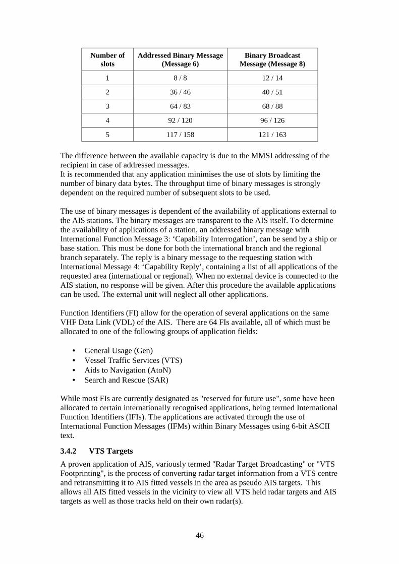
46
Number ofslots
Addressed Binary Message(Message 6)
Binary BroadcastMessage (Message 8)
1 8 / 8 12 / 14
2 36 / 46 40 / 51
3 64 / 83 68 / 88
4 92 / 120 96 / 126
5 117 / 158 121 / 163
The difference between the available capacity is due to the MMSI addressing of therecipient in case of addressed messages.It is recommended that any application minimises the use of slots by limiting thenumber of binary data bytes. The throughput time of binary messages is stronglydependent on the required number of subsequent slots to be used.
The use of binary messages is dependent of the availability of applications external tothe AIS stations. The binary messages are transparent to the AIS itself. To determinethe availability of applications of a station, an addressed binary message withInternational Function Message 3: ‘Capability Interrogation’, can be send by a ship orbase station. This must be done for both the international branch and the regionalbranch separately. The reply is a binary message to the requesting station withInternational Message 4: ‘Capability Reply’, containing a list of all applications of therequested area (international or regional). When no external device is connected to theAIS station, no response will be given. After this procedure the available applicationscan be used. The external unit will neglect all other applications.
Function Identifiers (FI) allow for the operation of several applications on the sameVHF Data Link (VDL) of the AIS. There are 64 FIs available, all of which must beallocated to one of the following groups of application fields:
• General Usage (Gen)• Vessel Traffic Services (VTS)• Aids to Navigation (AtoN)• Search and Rescue (SAR)
While most FIs are currently designated as "reserved for future use", some have beenallocated to certain internationally recognised applications, being termed InternationalFunction Identifiers (IFIs). The applications are activated through the use ofInternational Function Messages (IFMs) within Binary Messages using 6-bit ASCIItext.
3.4.2 VTS TargetsA proven application of AIS, variously termed "Radar Target Broadcasting" or "VTSFootprinting", is the process of converting radar target information from a VTS centreand retransmitting it to AIS fitted vessels in the area as pseudo AIS targets. Thisallows all AIS fitted vessels in the vicinity to view all VTS held radar targets and AIStargets as well as those tracks held on their own radar(s).

47
IFM 16 is used to transmit VTS targets, to a maximum of 7 in any one message.Because of the impact on VDL channel loading, IFM 16 should only be transmitted toprovide the necessary level of safety. Each VTS target message is structured as inTable 3-10:
Parameter Description
Type of Target Identifier Identifier Type:0 = The target identifier should be the MMSI number.1 = The target identifier should be the IMO number.2 = The target identifier should be the call sign.3 = Other (default).
Target ID Target Identifier. The Target ID should depend on Type of TargetIdentifier above. When call sign is used, it should be inserted using 6-bitASCII. If Target Identifier is unknown, this field should be set to zero.When MMSI or IMO number is used, the least significant bit should equalbit zero of the Target ID.
Latitude Latitude in 1/1000 of a minute.
Longitude Longitude in 1/1000 of a minute.
COG Course over ground in degrees (0-359); 360 = not available = default.
Time Stamp UTC second when the report was generated (0-59, or 60 if time stamp isnot available, which should also be the default value)
SOG Speed over ground in knots; 0-254; 255 = not available = default.
Table 3-10: VTS targets - Message StructureNote: A VTS target should only be used when the position of the target is known.However, the target identity and/or course and/or time stamp and/or speed overground may be unknown.
3.4.3 International Function Message 17 (IFM 17) - Ship Waypoints/RoutePlan
IFM 17 is used by a ship to report its waypoints and/or its route plan. If the reportingship uses this IFM 17 within an Addressed Binary Message, then the waypoints and /or the route plan will only be available to the addressed station, that is a Base Station(VTS centre) or another ship. If the reporting ship uses IFM 17 within a BroadcastBinary Message, then the information will be available to all other AIS stations in itsvicinity.
When transmitting a Route Plan the transmitting station can include up to 14 NextWaypoints (NWP), if available, and/or a route specified by a textual description. TheNWPs should be transmitted in the sequence of the intended passage.

48
Parameter Description
NWP Number of Next Waypoints (NWP) available (1 -14);0 = no Next Waypoint available = default; 15 = not used
WP i.Lon Longitude of Next Waypoint i in 1/10 000 min (±180 degrees,East =positive, West = negative).Field required if and as often as 1 ≤ i ≤ NWP, i = 1, 2, 3,…,14;Field not required if NWP = 0.
WP i.Lat Latitude of Next Waypoint i in 1/10 000 min (± 90 degrees,North = positive, South = negative).Field required if and as often as 1 ≤ i ≤ NWP, i = 1, 2, 3, …..,14;Field not required if NWP = 0.
Route specified byTextual Description
Description of the route information in textual form, e. g. "WestChannel"; maximum 20 characters using 6-bit ASCII;"@@@@@@@@@@@@@@@@@@@@" = not available(field must not be omitted).
Table 3-11: Ship Waypoints/Route Plan - Message StructureThe number of slots used for this message depends on the number of Next Waypointstransmitted as follows:
Number of Next Waypointstransmitted
0 1 2 3 4 5 6 7 8 9 10 11 12 13 14
Number of slots used for thismessage
2 2 2 3 3 3 3 4 4 4 4 5 5 5 5
3.4.4 IFM 18 -Advice of VTS Waypoints/Route PlanIFM 18 is used by a VTS centre to advise ships of the waypoints and/or route plansused in that particular VTS area. If the VTS uses this IFM 18 message within anAddressed Binary Message, then the information will only be available to theaddressed recipient, that is, one ship. If the VTS uses IFM 18 within a BroadcastBinary Message, then the information will be available to all other ships in VHFreception range of the transmitting VTS centre.
When transmitting this information the VTS centre can include up to 12 AdvisedWaypoints (AWP), if available, and/or a route specified by a textual description. Ifwaypoints are transmitted, then a recommended turning radius can be included foreach waypoint.

49
Parameter Description
AWP Number of Advised Waypoints (1 - 12);0 = no waypoint = default; 13 - 15 = not used
WP i.Lon Longitude of Advised Waypoint i in 1/10 000 min (±180 degrees,East = positive, West = negative).Field required if 1 ≤ i ≤ AWP, i = 1, 2, 3, ….., 12;Field not required if AWP = 0.
WP i.Lat Latitude of Advised Waypoint i in 1/10 000 min (± 90 degrees,North = positive, South = negative).Field required if 1 ≤ i ≤ AWP, i = 1, 2, 3, …, 12;Field not required if AWP = 0.
Advised Turning Radius i Advised Turning Radius at Advised Waypoint i in metres;0 = not available = default;1 - 4 095 metres. Field required if and as often as 1 ≤ i ≤ AWP, i =1, 2, 3, ….., 12;Field not required if AWP = 0.
Advised Route specifiedby Textual Description
Description of the advised route in textual form, e. g. "WestChannel"; maximum 20 characters using 6-bit ASCII;"@@@@@@@@@@@@@@@@@@@@" = not available(field must not be omitted).
Table 3-12: Advice of VTS Waypoints/Route Plan - Message Structure
The number of slots used for this message depends on the number of Next Waypointstransmitted as follows:
Number of Advised Waypoints transmitted 0 1 2 3 4 5 6 7 8 9 10 11 12
Number of slots used for this message 2 2 2 3 3 3 4 4 4 4 5 5 5
3.4.5 IFM 19 - Extended Ship Static and Voyage Related DataIFM 19 is used by a ship to report height over the keel (air draught), as a componentof voyage related data. This additional information would normally be supplied at theMaster's discretion or on request from a competent authority..

50
Parameter Description
Height over keel in 1/10 m; 2047 = height over keel 204.7 m or greater,0 = not available = default
This IFM uses one slot
Table 3-13: Height over Keel
3.4.6 IFM 40 - Number of Persons OnboardIFM 40 is used by a ship to report the number of persons on board, normally providedat the Master's discretion or on request from a competent authority.
Parameter Description
Number of Persons Current number of persons onboard, including crew members: 0- 8191;default = 0 = not available; 8191 = 8191 or more
This IFM uses one slot
Table 3-14: Number of Persons Onboard

51
CHAPTER 4
USING AIS SUPPLIED INFORMATION
4.1 BASIC OPERATION PROCEDURESThe shipborne AIS unit is connected to a power source, an antenna and to a variety ofon board equipment, or to the integrated navigation system. In addition, at the time ofinstallation, important, static, ship-related information has to be entered; this includesidentity, length and beam, type of ship and the location of the position-fixing antenna.
The unit will be fitted with, at least, a minimum keyboard and display (MKD) or adedicated dynamic display which interfaces with the AIS and performs two functions:display the unit’s operational status (which should be regularly checked) and targetinformation which is used as described in the following paragraphs.
4.2 OPERATION DURING THE VOYAGEThe AIS, once activated, will continuously and autonomously broadcast the vessel’sposition and all the static and dynamic information as required by IMO.
However, while the vessel’s speed and rate of turn manoeuvres will automaticallydetermine the update rate there remains a need for the Master or an authorised personto manually input, at the start of the voyage and whenever changes occur, thefollowing “voyage related data”
• ship’s draught;• type of hazardous cargo (most significant hazard carried);• destination and ETA (at master’s discretion);• route plan (way-points – at master’s discretion);• the correct and actual navigational status; and• short safety related short messages, when appropriate.
CAUTIONNOT ALL SHIPS CARRY AIS
The Officer of Watch (OOW) should always be aware that other ships and, inparticular, leisure craft, fishing boats and warships, and some coastal shore stationsincluding Vessel Traffic Service (VTS) centres, might not be fitted with AIS.
The OOW should always be aware that AIS fitted on other ships as a mandatorycarriage requirement, might, under certain circumstances, be switched off on theMaster’s professional judgement.
The potential of AIS as an anti-collision device is recognised and AIS may berecommended as such a device in due time. When used in conjunction with theapplication of the COLREG’s and good watchkeeping practice, it will enhance

52
situational awareness. To this end all target information within VHF range isdisplayed on the minimum display at all times and can be further integrated into anECDIS, ECS or radar display.
The minimum mandated display provides not less than three lines of data consistingof bearing, range and name of a selected ship. Other data of the ship can be displayedby horizontal scrolling of data, but scrolling of bearing and range is not possible.Vertical scrolling will show all other ships known to AIS.
4.2.1 ActivationAIS should always be in operation. It is recommended that the AIS is not switched offduring port stays because of the value of the ship information to port authorities.
Whether at sea or in port, if the Master believes that the continued operation of AISmight compromise the ship’s safety or security, the AIS may be switched off;however, the equipment should be reactivated as soon as the source of danger hasdisappeared. This might be the case in sea areas where pirates and armed robbers areknown to operate. It may be necessary to switch off AIS or to reduce the transmissionpower during some cargo handling operations. Actions of this nature should alwaysbe recorded in the ship’s logbook.
If the AIS is shut down, static data and voyage related information remains stored.Restart is achieved by simply switching on the power to the AIS unit. Own ship’s datawill be transmitted after a two-minute initialisation period.
4.2.2 Integrity CheckAIS provides:
• a built-in integrity test (BIIT) running continuously or at appropriate intervals;• monitoring of the availability of the data;• an error detection mechanism of the transmitted data; and• error checking of the received data.
If no sensor is installed or if the sensor (e.g. the gyro) fails to provide data, the AISautomatically transmits the "not available" data value. However, the integrity checkcannot validate the contents of the data presented to the AIS.
4.3 OPERATION IN A VTS AREA OR TSSAIS also assists vessels operating in a Vessel Traffic Service (VTS) area or TrafficSeparation Scheme (TSS) at the same time ensuring that the responsible shoreauthorities have the ability to easily identify vessels, to automatically receive fromthem a wealth of useful information and to communicate with them using the AISfunctionality.
Information received and transmitted through AIS enables shore authorities to bettermonitor and organise the traffic in the particular area of the VTS or Ship ReportingSystem (SRS) and to provide related information, assistance or transmit instruction tothe vessel related to its voyage in the VTS area.

53
4.4 OPERATION IN A COASTAL AREA, SHIP REPORTING SYSTEM(SRS) AREA OR EXCLUSIVE ECONOMIC ZONE (EEZ)
Additionally, AIS allows shore authorities to monitor vessels operating within theircoastal waters, designated mandatory SRS area or EEZ as appropriate. All vesselsfitted with AIS should be able to provide, automatically, the majority of any reportsrequired through the AIS’s continuous broadcast of the related static, dynamic andvoyage related information.
This will ensure a quicker response to emergencies such as Search and Rescue as wellas environmental pollution and will enable the coastal state to assess the navigationalrequirements or improvements that may be necessary to navigational safety in suchareas. Much value can arise from such monitoring, such as better traffic routeing, portand harbour planning and more safety related information exchange.
AIS is also provided with a two-way interface for connecting to long rangecommunication equipment. Initially, it is not envisaged that AIS would be able to bedirectly connected to such equipment. A shore station would first need to request thatthe ship makes a long range AIS information transmission. Any ship-to-shorecommunication would always be made point-to-point, and not broadcast, and oncecommunication had been established (e.g. INMARSAT C), the ship would have theoption of setting its AIS to respond automatically to any subsequent request for a shipreport, from that shore station.
The long distance reporting and polling functions allow areas to be monitored andvessel reports to be transmitted outside the normal AIS (VHF range) operational areasand allows for one type of equipment to perform all these functions automatically.
4.5 POTENTIAL OF AIS IN COLLISION AVOIDANCEA study of the German Marine Boards of Inquiry into the causes of collisions at sea inthe period 1983-1992 indicated that most of the so called “radar assisted collisions”(see figure 4.1) occurred in restricted visibility when radar provided insufficient,incomplete or ambiguous data4 The study concluded that many of these collisionscould have been avoided if the navigators involved had been able to access timely,and dynamic information (position, heading, speed and rate of turn etc) on the othervessel involved. AIS in the ship-ship application can now provide such dynamicinformation accurately and at high update rates, when target information is availableon the ships involved.
4 IMO Paper NAV 43/7/16, Automatic Identification Systems (AIS), Note byGermany dated 16 May 1997.

54
4.5.1 Risk of CollisionCOLREG Rule 7 - Risk of Collision - states that “Every vessel shall use all availablemeans appropriate to the prevailing circumstances and conditions to determine if riskof collision exists. If there is any doubt such risk shall be deemed to exist.”
The COLREGs oblige ships to apply all available means to detect the danger ofcollision and to take preventive measures. One of these means, especially duringreduced visibility, is shipborne radar; another aid now available is AIS.
The following sections contrast the performance of radar and demonstrate how AIScould mitigate many of the limitations of radar.
4.5.2 Limitation of radar performanceWhen considering radar performance for collision avoidance, a distinction needs to bemade between raw radar targets and tracked radar targets. The reliability of both, asdiscussed in the following section, involves issues of accuracy and the degree of delayof presentation.
4.5.2.1 Raw Radar TargetsThe shape of raw radar echo targets does not normally give a true representation ofthe real dimensions of a target. From the azimuth perspective, and depending on the
Figure 4-1 Some Examples of Collision Scenarios at Sea

55
target aspect and distance, the echo may be smaller at very long range or considerablylarger at medium ranges. This is a function of the antenna beam width. Thus, a ship atlong range, approaching the observing radar may appear to be a vessel orientated atright angles to its true movement .
This distortion of target information is especially true in the case of a large vesselsuch as a tanker with a high superstructure aft, where the visible radar echo isprobably reflections from the after structure and not the centre of the ship.
4.5.2.2 Radar in collision avoidanceThere are further aspects, such as the resolution of the monitor used and raw radarprocessing, which presents targets that are neither equivalent to the real target’sdimension nor symmetrical to it. Thus, in most cases, one cannot reliably assess, fromradar observation alone, the heading of a vessel, which may also differ from thecourse over ground.
When altering course, a vessel’s hull experiences two actions. Altering the position ofthe rudder, e.g. to starboard, causes the vessel to turn around its centre of rotation,which may be located a third of the ship’s length from the stem. This centre itself stillmoves straight on over ground, while the part ahead of the centre moves to starboardof the centre while the part aft of it turns to port of it. As a consequence the wholeship begins to change course over ground.
Figure 4-2

56
At the commencement of a course alteration the larger (radar reflecting) part of avessel moves in a direction opposite to the actual direction of turn and may give astronger radar echo because of the higher superstructure of the ship. It may, therefore,be difficult to instantaneously decide, from its raw radar presentation alone, the actualdirection of a manoeuvre by another vessel. Indeed, the instantaneous assessment maybe misleading and dangerous if acted upon.
4.5.2.3 Tracked Radar TargetsThe radar track of a vessel is usually “smoothed” by a filtering process to remove thedeviations caused by the alterations of reflectivity, pitch, roll and yaw. This processreduces true positional accuracy and creates a display delay. In the case of a coursealteration, it may take 5-10 antenna rotations to determine a target vessel’s movement.If the radar plot position of a target vessel is aft of its true centre of rotation, this mayalso produce a false indication of the target ship’s direction of turn.
4.5.2.4 ARPA/ATAThe limitations of automatic radar plotting aids (ARPA) and automatic tracking aids(ATA) are apparent from the IMO Performance standards. It should be noted that theinaccuracies mentioned therein refer to a movement on an unmodified course for oneto three minutes. For course alterations there is no specification at all.
4.5.2.5 AIS PerformanceAIS broadcasts the identity, position, heading, course over ground (COG), speed overground (SOG) and certain other relevant ship data at an update rate dependent uponthe ship’s speed or rate of turn during course alterations. Its performance enhancesshipborne radar in three aspects:
• AIS aims to achieve a positional accuracy of better than 10 m when associatedwith DGNSS corrections. This compares favourably with radar whoseaccuracy is a function of frequency, pulse repetition rate and beam width andwhich will often achieve a positional accuracy of 30-50 m
• Due to this higher position accuracy of AIS and less need for plot filtering, theposition and changes of course over ground can be presented with less delaythan by radar.
• The AIS provides further supplementary information, that is not readilyavailable from radar, about other vessels, such as identity, heading, COG,SOG, rate of turn and navigational status.
On the basis of this more accurate and complete information, the passing distancebetween vessels can be determined with higher accuracy and reliability. Cancellingactions can be avoided due to the fact that the relevant dynamic information can beprovided without delay and without wrong interpretation. From the navigationalstatus information any manoeuvring restrictions on a vessel become immediatelyevident and can be taken into account.
As a result, it can be seen that AIS provides more complete information thanshipborne radar. When used in conjunction with radar, it enhances the availableinformation. AIS can also assist in the identification of targets by name or call signand by ship type & navigational status, thus reducing verbal information exchange.

57
ARPA Heading
AIS Heading
Figure 4.3 – Comparison of Radar (ARPA) and AIS
The attached screen shot clearly shows the difference between the radar-ARPA andthe AIS information for collision avoidance. While the ARPA shows a crossingsituation the AIS clearly indicates the red to red situation
4.5.3 Display of AIS Target InformationThe information provided here is for guidance only and is intended to apply to thedisplay and integration of AIS target data in ‘stand alone’ as well as integratednavigational devices or systems. The aim is to provide performance based guidelinesrather than seek to stipulate operational user procedures.

58
Again, while certain recommendations for the display of AIS information areindicated, these do not exclude the application of alternative solutions, provided thefunctional requirements of these guidelines are met.
4.5.4 Definitions
Sleeping target A target symbol indicating the presence and orientationof a vessel equipped with AIS in a certain location. Noadditional information is presented until activated thusavoiding information overload.
Activated target A symbol representing the automatic or manualactivation of a sleeping target for the display ofadditional graphically presented information including:
- a vector (speed and course over ground);- the heading; and- ROT or direction of turn indication (if available)
to display actually initiated course changes.
Selected target A symbol representing the manual selection of any AIStarget for the display of detailed information in aseparate data display area. In this area, received targetdata as well as the calculated CPA and TCPA valueswill be shown.
Dangerous target A symbol representing an AIS target (activated or not)whose data contravene pre-set CPA and/or TCPAlimits.
Lost target A symbol representing the last valid position of an AIStarget before the reception of its data was lost.
4.6 OPERATIONAL REQUIREMENTSIn addition to the relevant performance standards, AIS information may be presentedand displayed according to the following interim guidelines.
4.7 PRESENTATION OF INFORMATIONIf AIS information is made available for a graphical display, at least the followinginformation should be displayed: (see resolution MSC.74(69), Annex 3 (AIS),paragraph 6):
• position• course over ground• speed over ground• heading• rate of turn, or direction of turn, as available

59
4.7.1 If information provided by AIS is graphically presented, the symbolsdescribed in Appendix 4-1 should be applied. In the case of a radar display,radar signals should not be masked, obscured or degraded.
4.7.2 Whenever the graphical display of AIS targets is enabled, the graphicalproperties of other target vectors should be equivalent to those of the AIStarget symbols, otherwise the type of vector presentation, (radar plottingsymbols or AIS symbols), may be selectable by the operator. The activedisplay mode should be indicated.
4.7.3 The presentation of AIS target symbols, except for sleeping or lost targets,should have priority over other target presentations within the display area,including targets from EPA, ATA or ARPA. If such a target is marked fordata display, the existence of the other source of target data may be indicated,and the related data may be available for display upon operator command.
4.7.4 The mariner should be able to select additional parts of the information fromAIS targets, which should then be presented in the data area of the display,including the ship’s identification, at least the MMSI. If the received AISinformation is not complete, this should be indicated.
4.7.5 A common reference should be used for the superimposition of AIS symbolswith other information on the same display, and for the calculation of targetproperties (e.g. TCPA, CPA.).
4.7.6 If AIS information is graphically displayed on a radar, the equipment shouldbe capable of appropriately stabilising the radar image and the AISinformation.
4.7.7 Target data derived from radar and AIS should be clearly distinguishable assuch.
4.7.8 The operator may choose to display all or any AIS targets for graphicalpresentation. The mode of presentation should be indicated.
4.7.9 If the display of AIS symbols is enabled, removing a dangerous target shouldonly be possible temporarily as long as the operator activates thecorresponding control.
4.7.10 The AIS symbol of an activated target may be replaced by a scaled shipsymbol on a large scale/small range display.
4.7.11 If the COG/SOG vector is shown, its reference point should be either theactual or the virtual position of the antenna.
4.7.12 Means should be provided to select a target or own ship for the display of itsAIS data on request. If more than one target is selected, the relevant symbolsand the corresponding data should be clearly identified. The source of thedata, e.g., AIS, radar, should be clearly indicated.

60
4.8 PROCESSING OF INFORMATION4.8.1 If zones or limits for automatic target acquisition are set, these should be the
same for automatically activating and presenting any targets regardless of theirsource.
4.8.2 The vector time set should be adjustable and valid for presentation of anytarget regardless of its source.
4.8.3 If radar plotting aids are used for the display of AIS information, these shouldbe capable of calculating and displaying collision parameters equivalent to theavailable radar plotting functions.
4.8.4 If the calculated CPA and TCPA values of an AIS target are less than the setlimits,
- a dangerous target symbol should be displayed and- an alarm should be given.
The pre-set CPA/TCPA limits applied to target data derived from different sensorsshould be identical.
4.8.5 If the signal of a dangerous AIS target is not received for a set time:
- a lost target symbol should appear at the latest position and an alarm begiven;
- the lost target symbol should disappear after the alarm has beenacknowledged; and
- means to recover the data for a number of last acknowledged lost targetsmay be provided.
Preferably this function may also be applied to any AIS target within a certaindistance.
4.8.6 An automatic display selection function may be provided to avoid thepresentation of two target symbols for the same physical target. If target datafrom AIS and from radar plotting functions are available, then the activatedAIS target symbol should be presented, if the automatic selection criteria arefulfilled, otherwise the respective symbols should be displayed separately.The operator should have the option to make reasonable changes to the defaultparameters of automatic selection criteria.
4.8.7 Means should be provided to display and acknowledge alarm messages fromown AIS. Indication should be given if own AIS is out of service or switchedoff.

61
4.9 HUMAN INTERFACEAs far as practical, the user interface for operating, displaying and indicating AISfunctions should be equivalent to the other relevant functions of the navigational aid.
Note:AIS uses WGS84 datum. Users should be aware that alternative datums used inelectronic aids or referenced on a paper chart may induce positional errors.

62
Appendix 4-1
AIS target Symbol Description of symbol
AIS target (sleeping)
An isosceles, acute-angled triangle should be used withits centroid representing the target’s reference position.The most acute apex of the triangle should be alignedwith the heading of the target, or with its COG, ifheading information is not available. The symbol of thesleeping target may be smaller than that of theactivated target.
Activated AIS target
An isosceles, acute-angled triangle should be used withits centroid representing the target’s reference position.The most acute apex of the triangle should be alignedwith the heading of the target, or with its COG, ifheading information is not available.The COG/SOG vector should be displayed as dashedline starting at the centroid of the triangleThe heading should be displayed as solid line of fixedlength starting at the apex of the triangleA flag on the heading indicates a turn and its directionin order to detect a target manoeuvre without delayA path predictor may also be provided
Selected targetA square indicated by its corners should be drawnaround the target symbol.
Dangerous target
A bold line clearly distinguishable from the standardlines should be used to draw the symbol. The size ofthe symbol may be increased. The target should bedisplayed with: vector, heading and rate of turnindication. The symbol should flash untilacknowledged.The triangle should be red on colour displays.
Lost target
A prominent solid line across the symbol,perpendicular to the last orientation of the symbolshould be used. The symbol should flash untilacknowledged. The target should be displayed withoutvector, heading and rate of turn indication.
Table 4-1: Recommended AIS Target Symbols– If colour fill is used no other information should be masked or obscured.– Base stations may transmit information on targets tracked by other means. If
these targets are displayed they should be presented using symbols clearlydistinguishable from the symbols above.
– Further symbology for special situations will be developed.

63
CHAPTER 5
OPERATION IN THE SHIP - SHIP MODE
The AIS is a ship to ship, ship to shore broadcast system. In the ship to ship mode ofoperations, IMO has provided “Guidelines on Automatic Identification Systems (AIS)Operational Matters of AIS” for the mariner. These were not finalised when thisdocument was issued. IALA has been involved extensively in the development ofthese guidelines.
The responsibility of IALA is in the Aids to Navigation and VTS areas of theMaritime community. As such IALA is undertaking to provide a definition of an AISshore station and a unique AIS AtoN station.
This is a major work that will take a considerable amount of time to complete due tothe many decisions that will need to be make in order to define these stations.
There is a further definition of an AtoN station in Chapter 14 but it is preliminarywork only.

64
CHAPTER 6
INFORMATION DISSEMINATION
6.1 PRESENTATION OF AIS INFORMATIONThe following items have been identified in this document as future item to beaddressed. Each is being discussed in many forums and there are noconclusions to be published at the time of printing of this document.
6.1.1 Symbology
6.1.2 Displayed on Radar
6.1.3 Displayed on ECDIS
6.1.4 Dedicated Graphic Display
6.1.5 Integrated Navigation Systems
6.1.6 Use of AIS Information
6.1.7 Navigation Warnings
6.1.8 Meteorological Warnings
6.1.9 Shipping Information
6.1.10 Onboard Operation
6.1.11 Interfaces.
6.1.12 ECDIS

65
6.1.13 Radar
6.1.14 Independent display
6.1.15 Gyro
6.1.16 Rate of turn
6.1.17 Pitch and roll indicate
6.1.18 VDR
6.1.19 Speed log
6.1.20 GNSS/DGNSS

66
CHAPTER 7
PILOTAGE
7.1 OVERVIEWIn pilotage areas like ports, harbours, rivers and archipelagos, the need for AIS withhigh update rates is evident; the AIS will be invaluable for navigation, reporting, andcommunication purposes.
The limitations of the ARPA radar to track vessels due to target swapping from avessel to land, beacons, bridges and other vessels makes the ARPA capabilities verylimited in narrow and congested waters. AIS used together with ARPA radar enhancesits function.
Safety will be improved by using AIS in pilotage waters and the broadcast AIS willachieve this by:
• identifying vessels by name, heading, course over ground (COG), speed overground (SOG), size, draught and type of vessel.
• detecting and identifying vessels especially in restricted visibility e.g. behind abend in a channel or behind an island in an archipelago.
• predicting the exact position of a meeting with another vessel(s) in a river, portor in the archipelago. Thus allowing for the correct manoeuvre to be made forcollision avoidance purposes.
• identifying which port or harbour a vessel is bound for• detecting a change in a vessel’s heading almost in real time
7.2 SILENT VTSThe AIS allows the silent and automatic exchange of information with other vesselsand VTS centres, leaving port operation VHF channels available for safety purposesand emergency situations. Thus AIS reduces the workload on the bridge of the vesseland also in the VTS centre. In ports where the density of the traffic is low, the AISfitted vessels may form their own “Silent VTS” without any shore station. In busyports AIS will reduce the VTS operators’ workload and allow them to increase theirefficiency in traffic management, information services and other tasks.
7.3 SHORE TO VESSEL AIS SERVICESThere are existing international AIS messages designed to facilitate the receptiononboard of online and static information from shore such as hydrographical,hydrological, meteorological, Aids to Navigation, and Warning messages. Localspecific messages can also be made available to fit local demands.
7.4 POSSIBLE FUTURE USE OF AIS IN PILOTED WATERSIn addition to the use of AIS standard messages there is a need to use specialmessages created for use in a specific pilotage area because of differing localconditions.

67
Examples of information that could be exchanged via AIS in piloted waters:
• actual wind direction and speed• actual current direction and speed• actual water level• actual water and air temperature• floating aids to navigation on station or off station• fixed aids to navigation as reference targets for radar• aids to navigation status/identity• virtual aids to navigation• local management messages• locks open/closed• bridges open/closed• tension power on tug lines• orders to tug boats• traffic information from the VTS
AIS also provides the facility for a VTS centre to broadcast VTS targets to vessels. AVTS target is any target that can be displayed at the VTS centre including radartargets, DF targets and ARPA targets. What this means for the pilot is that he will beable so see all the vessels the VTS operator sees, even if those vessels do not have anAIS onboard.The creation and use of these special messages to fulfil local requirements will assistboth the pilot and the VTS in their respective tasks. For example, the AIS can providea bird’s eye view of a docking operation with tugboats connected or pushing includinginformation such as bollard pull, directions of pull and even issuing the commands tothe tugboats through the Pilot Pack.
Special local applications in e.g. rivers, canals, harbours and archipelagos will mostcertainly be one of the tools for a pilot or a master with pilot exemption to make theirjob more efficient. The AIS is able to handle both internationally agreed messages andlocally designed messages. This makes the AIS one of the major tools for the pilot inthe future.
7.5 PORTABLE PILOT PACKThere are two types of portable carry onboard pilot AIS equipment. The first type is apilot workstation combined with a portable AIS. The second type is a pilotworkstation, which connects to the pilot port connector of an onboard AIS.
• A pilot workstation combined with portable AIS is used primarily to providemarine pilots with the capability to carry onboard an AIS station when pilotingvessels not fitted with AIS. Such a Pilot Pack contains GNSS/DGNSS, AIS,(optional) heading sensor, and a workstation. The heading sensor is essential ifthe vessel is using the Pilot Pack for navigating in waters where there arefrequent course alterations. Without the heading sensor the AIS will notprovide sufficient information to other vessels in the vicinity.
• Most of the vessels that are piloted will be fitted with AIS according to theSOLAS convention. The onboard AIS has a pilot/auxiliary input/output port

68
which provides the facility to forward the own vessel’s GNSS/DGNSSinformation, heading, and (optional) rate of turn continuously, independentlyof (i.e. faster than) the standard AIS reporting rate. The pilot will receive allother AIS information at the standard rate. This allows pilots to plug in theirown pilot portable workstation to the onboard AIS in order to receive morefrequent own ship navigation information. In addition the pilot port providesthe pilot the facility to forward information to other vessels in the vicinity or tothe local VTS.
• When installing the AIS there should be connectivity to the AIS pilot portfrom those locations at which the pilot would use his workstation (seeappendix 12-A). In addition a power supply should be available to the samelocation(s).

69

70
CHAPTER 8
VESSEL TRAFFIC SERVICES
IMO Assembly Resolution A.857(20), Guidelines for Vessel Traffic Services,establishes the following tasks that should be performed by a VTS:
“A VTS should at all times be capable of generating a comprehensive overview of thetraffic in its service area combined with all traffic influencing factors. The VTSshould be able to compile the traffic image, which is the basis for the VTS capabilityto respond to traffic situations developing in the VTS area. The traffic image allowsthe VTS operator to evaluate situations and make decisions accordingly. Data shouldbe collected to compile the traffic image. This includes:
• Data on the fairway situation, such as meteorological and hydrologicalconditions and the operational status of aids to navigation;
• Data on the traffic situation, such as vessel positions, movements, identities andintentions with respect to manoeuvres, destination and routing;
• Data of vessels in accordance with the requirements of ship reporting and, ifnecessary, any additional data required for the effective operations of VTS.
This chapter of the IALA Guidelines on AIS seeks to identify, for the benefit of VTSauthorities, the ways in which AIS contributes to the achievement of the above tasks.
8.1 BENEFITS OF AIS
8.1.1 Automatic Vessel IdentificationAIS brings to the mariner many benefits. Principal amongst these, as the nameimplies, is the automatic and immediate provision of vessel identity (MMSI, call signetc), thereby facilitating rapid radio communication where necessary. This benefit isof equal, if not even greater, value to VTS authorities.
Most VTS organisations require vessels to report to the VTS centre when approachingor entering the VTS area. Achieving vessel identity relies on such vessels reportingboth identity and location to the VTS centre, and the VTS operator then correlatingthis information with an unassigned radar track.
The process is time consuming and wholly reliant on the co-operation of participatingvessels. It is not uncommon for some vessels to fail to comply with this requirement,thereby creating a potentially dangerous situation, and creating further distraction forthe VTS operator. Even where VHF direction finding equipment is fitted, the VTStraffic image is still reliant on vessels reporting identity via VHF thereby permittingthe correlation of identity with the radar track identified by DF. AIS will helpovercome the safety weaknesses and time consuming procedures, inherent in thepresent arrangements.

71
8.1.2 Improved Vessel Tracking
8.1.2.1 Wider geographical coverage.AIS data will be received by other AIS units, or by base or repeater stations. Thuswhere a VTS organisation is fitted with such equipment, it will be capable ofreceiving both identity and precise location of a vessel at the maximum receptionrange of the VHF radio communications frequency. As a consequence, it will oftenpermit detection of vessel target well outside conventional radar range. Even wherethis is not possible, due to the need to screen base stations from adjacent VHFinterference, extended VTS detection range may be achieved by the installation ofadditional base or repeater stations connected into a network at much lower cost thanradar.
8.1.2.2 Greater positional accuracy.AIS aims to achieve positional accuracy better than 10 metres when associated withDGNSS correction signals. This compares favourably with radar, which as a functionof frequency, pulse repetition rate, and beam width, will often only achieve positionalaccuracy in the range 30 to 50 metres.
8.1.2.3 Absence of “radar shadow” areas.In coastal and harbour waters radar tracking of vessels can be masked, or otherwiseaffected by the proximity of land and buildings. The resultant “shadow” areas cancause a radar based VTS to lose track, thereby denying the VTS centre the ability tomonitor accurately vessel movement at what could be a critical time. The loss oftracking will invariably result in the need to reacquire and re-identify lost tracks,thereby increasing the work load within the VTS centre.
Whilst AIS tracks will avoid the great majority of such effects, the very closeproximity of buildings and bridges, sometimes known as the “urban canyon” effect,can cause difficulties for AIS transponders in heavily built-up areas. This is aconsequence of inhibiting either the reception of the differential GNSS signal by theAIS transponder, or the transmission of the subsequent AIS message.
8.1.2.4 Traffic image accuracyVessel tracking can similarly be interrupted when two vessels pass close to oneanother, with the result that the radar tracking of one contact is confused by theproximity of the other. Importantly, this can result in the identity of one tracktransferring or “swapping” to the other. Self-evidently, such a situation introduces apotentially dangerous inaccuracy in the vessel traffic image, unless noticed andrectified quickly by VTS operators. Again, the consequence of this phenomenon isfurther work for the VTS centre. The more precise tracking associated with AIS hasbeen shown to prevent the incidence of “track swap”.
8.1.2.5 Real time manoeuvring data.Radar based VTS systems will typically provide details of a vessel’s course and speedover the ground. Of necessity, this information is historical in that it is calculated

72
from the track made good by a vessel. In contrast, AIS will provide all recipients withcertain elements of real time manoeuvring data such as Ships Heading and Rate ofTurn. These are derived directly from the vessel navigation systems and are includedautomatically in the Dynamic Message broadcast by the AIS.
8.1.2.6 Weather effects on tracking performance.Navigational radar performance is often adversely affected by precipitation as afunction of the radio frequency on which it operates. In heavy rain or snow, effectiveradar tracking is sometimes unachievable, even with the use of modern suppressiontechniques. VHF radio transmissions on the other hand are not so attenuated. As aconsequence, a VTS centre is much more likely to maintain an accurate traffic imagein adverse weather where that tracking is based on AIS data.
VHF radio transmissions can be affected by atmospheric ducting. In these conditions,VHF reception ranges can be greatly extended. Where such an enhanced receptionrange brings with it the detection of greatly increased AIS messages, the system willautomatically overcome the risk of overloading by ignoring signals originating fromvessels at greatest range, and re-using the slots so gained.
8.1.2.7 Provision of more precise navigational advice.It follows that where a VTS centre is able to receive AIS information from vesselswithin or adjacent to its area, the quality, accuracy and reliability of vessel trackingwill be improved markedly. As a consequence, that VTS centre will be able toprovide more precise navigational advice, as and when required, or when deemednecessary. Moreover, the availability of certain real time manoeuvring data withinthe VTS centre will enable VTS operators to appreciate more rapidly, and in greaterdetail, actual vessel movement. It should be stressed, however, that this facility alonewill not enable a VTS centre to provide detailed manoeuvring advice to a vessel.
8.1.3 Electronic transfer of sailing plan informationWhere AIS is integrated into a VTS system, it becomes possible for vessels and theVTS centre to exchange passage information such as intended way points, providedthe appropriate software is available.
8.1.4 Electronic transfer of safety messages.The facility available within AIS for the transmission of short safety messages makespossible the electronic broadcasting from a VTS centre of local navigation warnings,and similar safety related messages.
It is anticipated that VTS centres may have the capability to broadcast, via AIS, localchart corrections to ECDIS fitted ships.
8.1.5 Automatic indication of Voyage Related Information (cargoes, dangerousgoods, etc)
Vessels are normally required to report to the VTS authority that dangerous goods arebeing carried. The AIS voyage related message permits the inclusion and automatictransmission of this information.

73
8.1.6 Impact on VHF communicationsAs described earlier, a major benefit of AIS is the consequential reduction of VHFvoice messages. This in turn reduces the reliance placed on vessels understandingsuch messages from a VTS centre and vice versa.
8.1.7 Archiving dataThe automatic availability within a VTS centre of AIS data for each vessel facilitatesthe rapid and comprehensive recording, replay and archiving of data.
8.1.8 System redundancyBy equipping VTS centres with AIS, an alternative method of tracking andmonitoring vessel navigation is introduced, thereby improving system redundancysignificantly.
8.1.9 Potential for interaction within regional AIS networkIncreasing emphasis is being placed on networking VTS centres on a regional basis.Such an arrangement facilitates greater efficiency by making possible the rapidtransfer of vessel details between different centres. Adoption of AIS within therelevant VTS centres may contribute toward this process.
8.1.10 Improved SAR managementMany marine and VTS authorities are equipping SAR capable units, including aircraftand helicopters, with AIS. The AIS voyage related message permits a vessel totransmit the number of persons onboard. Whilst this is not mandatory for vessels atsea, it can be made a formal requirement in a VTS area. The provision of suchdetails, and the ready identification and location of SAR units greatly facilitates themanagement and evaluation of any SAR response.
8.2 INSTALLATION OF AIS INTO A VTS - ISSUES TO BECONSIDERED
8.2.1 Number/location of base stations/repeatersIn deciding the size, and thus cost, of integrating AIS into a VTS system, a carefulstudy needs to be undertaken to establish practically the number and location of baseand repeater stations required to achieve full and reliable coverage of the expectedtraffic load. Although VHF reception is greatly influenced by antenna location andheight, operation in a noise electronic environment may necessitate the installation ofadditional base stations in order to reduce susceptibility to interference.
8.2.2 Interoperability with adjacent VTSWhere it proves necessary to use more than one centre, or where a VTS authorityinvolves more than one VTS centre, the method of connecting the componentelements into a local network needs to be given careful consideration. In particular,the existence of, or plans for a regional network may necessitate using a localnetworking solution, which is compatible with national and international networks.
8.2.3 Availability of VHF Communication channels.Two maritime VHF Channels have been allocated by the ITU for the international useof AIS in its primary ship-to-ship mode. What is not yet certain, is whether additional

74
local channels will need to be allocated to support the operation of VTS within certaincongested VTS port environments. The need for such additional channels will be atits most acute where large numbers of vessels navigate within a VTS area, and wherethe VTS centre has a particular interest in deriving vessel identity at maximum range.As has been described previously, AIS in an overload situation will discount AISsignals received from the extremity of an area, before those emanating from vessels orcraft close to the receiving station.
8.2.4 Availability of national/regional/local DGNSS correctionsIn order to monitor vessel navigation with the 10 metre accuracy potentially possible,a reliable DGNSS correction signals will need to be made available to all vesselsthroughout the VTS area. Such services are provided nationally or regionally in someareas. Where such a service does not exist, a VTS authority may consider providingthese corrections itself. It is technically possible to transmit the relevant correctionsusing the AIS itself.
8.3 OTHER ISSUES TO BE TAKEN INTO CONSIDERATION
8.3.1 Integration of AIS into existing radar based systemsRadar based VTS systems often differ in the way radar video is handled andprocessed, prior to presentation of the traffic image. System design and age are thuslikely to influence the options for successfully integrating AIS. A full appreciation ofthose options, together with any consequences, will normally only be possible afterconsultation with the relevant manufacturers.
In many VTS areas, vessel traffic is varied and includes both SOLAS and non-SOLAS vessels. In these circumstances, radar will remain the primary sensor fordetecting vessels not fitted with AIS. Economies in infrastructure are thereforeunlikely.
AIS data is transmitted at variable rates depending upon vessel speed and manoeuvre.In contrast, radar data is generated at a constant rate as defined by the antenna rotationspeed. The integration of AIS into a radar based VTS system thus needs to be capableof achieving and maintaining the correlation of AIS and radar data originating fromthe same vessel, despite unpredictable variations in data rates. The potential benefitsof AIS would be quickly reduced, should the process of integration result in thegeneration of numerous false tracks.
8.3.2 Use of electronic chartsVTS systems have traditionally used a schematic representation of the geographicaland hydrographic features of the relevant area as the background to the traffic image.The accuracy of such representations, however, is not suitable for precise navigation.With the advent of electronic charts, there are clear benefits to be gained from usingsuch charts as the background to the traffic image. By so doing, vessel navigationmay be monitored, and advised, in relation to precise charted features. In VTSsystems not fitted with electronic charts, such advice can only be given in relation toradar detectable features, such as coastline or navigational buoys, or as depicted onexisting VTS display diagrams.

75
Where reliance is to be placed on electronic charts for this purpose, it is important thatthey are issued by an approved hydrographic office, accurate, and up to date. It isanticipated that VTS authorities will be able to broadcast local chart corrections tosuitably equipped (ECDIS/ECS) vessels and to issue navigational warningselectronically using AIS.
In confined waters, it is likely that VTS operators in monitoring vessel manoeuvreswill occasionally have need to reduce the scale of their displays. In suchcircumstances, it will be important that the electronic chart acting as the backgroundto the traffic image, is capable of showing increasing levels of survey detail, asoperators reduce the scale on their displays. This will only be possible where theelectronic chart is compiled from source survey data, rather than from an existingpaper chart. In these circumstances, it will also be important that the charted locationof radar sites is accurate to a maximum of 10 metres, if errors between radar and AISgenerated tracks, which will be all the more obvious at reduced range scales, are to beavoided.
IHO standard S52 defines the standards for symbols and colours on official electroniccharts. Four variations of the basic colour scheme are available. These colourschemes, whilst optimised for navigation in varying light conditions on the bridge of avessel, may not be suitable for VTS purposes ashore, particularly where operators arerequired to study a display constantly for long periods.
8.3.3 Choice of VTS SymbolsAppendix 12-A shows the choice of AIS symbols allocated for use onboard vessels.
These symbols may be found to be unsuitable for VTS purposes, for two reasons.Firstly, those selected to represent AIS tracks may need to be accommodated logicallywithin an existing framework of symbols. Secondly, VTS centres will often haveneed to represent visually on the traffic image, a much wider range of informationthan is necessary onboard a vessel. For example, traffic management may necessitatethe use of symbols which depict different types and sizes of vessels. Alternatively, itmay be necessary to show which vessels have pilots embarked, and which do not.
Where it is required for a VTS to transmit a pseudo-AIS target to an AIS/ECDIS fittedvessel, it will be necessary for that information to be transmitted in terms which willbe recognised by the vessel, however, it is represented internally within a VTS centre.
8.4 AIS AND AIDS TO NAVIGATION (ATON)
A further application of AIS is as an AtoN (refer to paragraph 1.7).
The remote control and monitoring of aids to navigation has been developed primarilyto enable service providers to ensure that aids and supporting systems are functioningcorrectly and where required to organise maintenance.
Until now, there has been no simple and universal method of communicating suchinformation. The introduction of AIS presents an opportunity to provide suchinformation to service providers and mariners, using internationally standardised andrecognised equipment, message protocols and frequencies.

76
The operation and performance of aids to navigation can be monitored or controlledusing an AIS data link as the interface with the service provider. It is possible to havean aid transmit its identity, operational status and other information such as real timewave height, tidal stream and local weather to ships nearby or to the service provider.Buoys that can transmit an accurate position, perhaps based on DGNSS, can bemonitored to ensure that they are on station. Performance monitoring, remotelychanging operating parameters, and activating back-up equipment are also madepossible by the use of AIS.
8.5 AIS FOR METEOROLOGICAL AND HYDROLOGICALINFORMATION
Another application, which is expected to be widely used, is the transmission ofmeteorological and/or hydrological data. Where such an application is intended forinternational use, the message format will be registered by IALA prior to being madeavailable to system manufacturers. This will facilitate the correct presentation of theinformation on systems from different manufacturers.
Options for implementing this application include:
• Connecting a sensor directly to a local AIS-unit, which then broadcasts therelevant information.
• Several sensors can be connected to a shore station network via a datacommunication system. Information can then be broadcast as required.
• A sensor can be co-located with an AtoN equipped with AIS. The AIS-unitcan then be used to broadcast both the AtoN information and meteorologicaland/or hydrological information using separate messages.
The information to be broadcast will depend on the operational requirement and theavailability of measuring and processing equipment. Examples include:
• Wind speed, average and gust values
• Wind direction
• Water level
• Water temperature
• Air temperature
• Current speed and direction on different depths
• Tide information
Such data permits the presentation of real time information at receiving stations,including onboard ships within VHF range.

77
8.6 PERSONNEL AND TRAININGFor information on personnel and training, refer to IALA Model Courses V103-1,V103-2, V103-3 and its associated task book and V103-4.
8.7 SHORT TERM ACTION BY VTS AUTHORITIESAIS equipment is to be implemented as a mandatory carriage requirement underSOLAS Chapter V for newly constructed vessels from 1 July 2002 and progressivelythereafter to other vessels by 1 July 2008.
VTS authorities therefore need to consider, as a matter of priority, whether they intendintegrating AIS into their VTS system. As the previous paragraphs will havedemonstrated, the inclusion of AIS into a VTS system significantly enhances theprecision and reliability with which AIS equipped vessels may be monitored, and thusenhances safety.
AIS also has the potential to improve efficiency in vessel traffic and portmanagement. The degree to which this potential may be realised will vary dependingon the operational circumstances. It is for each VTS authority to make thatassessment.
8.8 CAUTIONARY NOTEIn order to avoid a situation whereby AIS fitted vessels incorrectly believe that a VTSauthority is receiving data being transmitted via the AIS, all VTS authorities will needto publish by appropriate means their status in respect of AIS. Where applicable, thedate on which they intend to incorporate AIS should also be promulgated well inadvance.
_____________________________

78
GUIDELINES
ON
UNIVERSAL SHIPBORNE
AUTOMATIC IDENTIFICATION SYSTEM (AIS)
__________________________________________________
PART 2
TECHNICAL ASPECTS OF AIS

79
CHAPTER 9
DESCRIPTION OF SYSTEM ARCHITECTURE OF THE AIS
9.1 INTRODUCTION TO THE TECHNICAL PART OF THE IALA AISGUIDELINES
Previous chapters have concentrated on the operational aspects of the AIS, i.e. on thedescription of what the AIS is supposed to do under what circumstances in operationalterms. This chapter introduces a set of chapters that will deal with the technicalaspects of the AIS.
This part of the IALA AIS Guidelines intends to satisfy the information need of
• anyone, in particular an interested user, who wishes to gain a betterunderstanding of the technical aspects of the AIS: While a user of the AIS mayfeel that knowing the operation of AIS is sufficient he/she will discover thatunderstanding the technical principles of AIS will lead to a greaterappreciation of the benefits of AIS but also its limitations. Hence the overalleffectiveness of the application can be optimised.
• integrators and application designers, both operational and technical, whenseeking both a comprehensive and an accurate description of the basic serviceswhich the AIS delivers, without wishing to go into the highly technicalreference documents. It should be noted, that this description was drafted froma shore-side point of view, i.e. it focuses on AIS services delivered at theshore-side interface of an AIS base station. However, many fundamentaldescriptions may also be of value for the AIS services delivered at theinterfaces of the mobile AIS stations.
• competent authorities who wish to deploy a shore-based AIS infrastructureand seek well structured guidance in the planning and the procurement of thatshore-base AIS infrastructure.
The large and still expanding volume of relevant international documents andstandards has created the need for a reference guide. This part of the IALA AISGuidelines refers the reader to the paragraph or section of the appropriateinternational document relating to the AIS function under consideration.
The purpose of this chapter is to give a broad introductory overview of the system"AIS" as a whole. It introduces the layered structure of the AIS and the applicationsusing the AIS derived information. This chapter also indicates where the differentkind of AIS stations fit into the layered concept of the AIS as a whole, i.e. it maps theAIS stations to the layers of the ISO/OSI-layer model.
The purpose and functions of the AIS can be expressed in terms of services provided.The most fundamental services of the AIS are called Basic AIS Services (BAS). Theymake use of the diverse features of the AIS VHF Data Link (as described inRecommendation ITU-R M.1371-1 in connection with the IALA Recommendation onTechnical Clarifications of Recommendation ITU-R M.1371-1) and the diversefeatures of the different AIS stations (as described e.g. in the appropriate IEC

80
standards and the before mentioned IALA Recommendation). They can be describedin a common format. All available BAS are described in Chapter 10.
This description of the BAS does not make redundant the referenced documents, i.e.the appropriate international standards or introduce new system features. However,this description of the BAS binds together - in a comprehensive and highly accuratemanner - all information items from various sources that are essential to understandwhat is being delivered in functional terms on a given interface on the recipient's side.It is also the basis for an assessment of the usefulness of a particular AIS service for aparticular intended application in terms of accuracy, frequency, reliability etc.
The AIS frequency management was given a separate chapter as both a very powerfuland very complex BAS, which should be carefully considered before using it.Competent authorities are responsible both for the decision to implement AISfrequency management - thus drawing away from the global default AIS frequencymanagement - and to manage the regional AIS frequencies. In that region, this serviceaffects the AIS as a whole - for good and for worse. Therefore, detailed guidance forcompetent authorities that have identified a need for AIS frequency management isgiven in Chapter 11.
While Chapters 9, 10, and 11 deal with the AIS as a whole, Chapters 12 to 15 turn tospecific AIS stations. Shipborne mobile AIS stations (Chapter 12), AIS base andrepeater stations (Chapter 13), Aids-to-Navigation AIS stations (Chapter 14), andSearch-and-Rescue Aircraft AIS stations (Chapter 15), all exhibit some specialfeatures.
After the introduction of the individual varieties of AIS stations, coastal-wide issuesof an AIS shore infrastructure are considered, Planning of coastal AIS VDL coverage(Chapter 16), configuration management of AIS shore infrastructure (Chapter 17),processing AIS data from multiple base stations (Chapter 18), and AIS shorenetworking (Chapter 19). Chapters 16 - 19 also reference Annex 4 where concreteguidance is given to administrations with regard to what requirements are advised tobe included in any call for tender for a shore based AIS infrastructure in order toprocure a functioning, flexible and future-proof shore-based AIS infrastructure.
Long Range Applications (Chapter 20) addresses the special consideration for longrange use of AIS. This does not make use of the AIS VDL but uses appropriate longrange communication links to provide a means for ship reporting and tracking systemswhich cannot use AIS VHF coverage due to the distance to the next AIS base stationashore.
9.2 SYSTEM ARCHITECTUREThis section describes the framework, which is used in the design of the AIS.
9.2.1 The AIS - a system designed using functional layersThe AIS is designed as a modern electronic system. Modern electronic systems aregenerally designed by structuring them in stacks of functional layers.

81
9.2.1.1 Open System Interconnection 7-Layer ModelThere is one internationally recognized standard model of how to structure thefunctionality of a complex system in layers. This layer model consists of 7 layers andwas developed by the International Standards Organization (ISO). The AIS has beendesigned using this model. In order to fully understand the AIS technology it is vitalto understand this model.
The model is called the Open Systems Interconnection Reference Model (OSI model,for short). It was originally developed to provide a general structure forunderstanding and assisting in the development of digital links between computer-based systems. This general structure was developed to help engineers createinternationally standardized systems that use a number of different data andcommunication protocols.
The OSI model is used in the documents, which define the AIS technology, inparticular the Recommendation ITU-R M.1371-1 and the IALA Recommendation onTechnical Clarifications on Recommendation ITU-R M.1371-1, to help identify,define, and describe features that the AIS must posses. While designed primarily forcommunications systems, the OSI model was found to be satisfactory as an organizingframework for AIS.
The OSI model partitions the digital computer communications process into sevenlayers of services. The seven layers interconnect to provide the functions needed tomove digital information. Each layer provides a service that ensures that digitalinformation is transferred correctly. Standards and methods can be defined for eachlayer.
The top three layers of the model are used to describe the application-orientedprocesses of exchanging AIS-related information and the AIS-related supportfunctions needed. The bottom four layers of the model describe the most fundamentalprocesses needed to connect two or more AIS devices and control information flowwithout errors, loss of information, or duplication of information. The followingbriefly describes the services provided by each layer in the OSI model, Figure 9-1.
- Application Layer: This layer interfaces directly to, and performs commonapplication services for, the application process. It directly supports theexchange of information between application programs at both ends of thedata path. This layer is not part of the applications that either generate or usethe information, which can be the mariner or a VTS operator using AIS as wellas automated applications. Specific applications are external to the OSI model,i. e. the shipboard navigation using AIS and the traffic management processes(performed in a VTS centre) using AIS lies above the OSI model.
- Presentation Layer: Provides the process to transform information into amutually agreed format. It relieves the Application Layer of concernregarding syntactical differences in data representation between the two “end-user” applications.
- Session Layer: Responsible for managing the connection betweencooperating applications. It manages such things as link termination andrestart procedures.
- Transport Layer: Manages the connection between the two end nodes in theinformation exchange. It provides the transparent transfer of information

82
between the two “end-user” applications, thus relieving the upper layers fromany concern with providing reliable and cost-effective data transfer.
- Network Layer: Responsible for providing the functional and proceduralmeans of transferring variable length data sequences from a source to adestination. It performs routing, flow control, and segmentation/de-segmentation functions.
- Data Link Layer: Provides the reliable transfer of data frames over thephysical layer. It can be used to detect and correct some of the errors thatoccur in the Physical Layer.
- Physical Layer: Responsible for the mechanical, electrical, functional, andprocedural aspects of the data link between the “end-users”. It establishes andterminates the communication medium connection, manages contentionresolution and flow control, and converts the representation of digital data inthe user equipment and the corresponding signals transmitted over thecommunications medium. The details of the physical layer design are drivenby the characteristics of the communications medium, i. e. by thecharacteristics of the VHF maritime mobile band. Its characteristics are asignificant factor in determining the overall design.
While not actually part of the ISO/OSI model, the VHF maritime mobile band as thetransport media of the AIS is introduced here as an “eighth layer” in order to drawattention to signal propagation and electronic interference issues. In the IALA AISGuidelines the eighth layer will be referred to as the “Propagation Layer”.
- Propagation Layer: This layer provides the connection between theinformation source and the destination. The uncontrolled characteristics of thepropagation layer have a significant impact on the design and operation of thelayers above it and performance of the overall system. Many of theprecautions taken in higher layers are designed to combat problems that existin this layer.
Each layer communicates with the layers above and below it. Figure 9-1 shows howthese layers can be organized into “stacks.” Note that each layer exists at both thetransmission and reception side. Each layer in the reception stack must be designedwith the detailed knowledge of what the corresponding layer in the transmission stackis doing to the information passing through that layer. It is the detail of this type ofinformation that makes it necessary to use clearly agreed upon methods and standardsto implement the AIS functionality and AIS-based applications. It is also important tokeep in mind that an unlimited number of reception stacks can be simultaneouslyreceiving the signal produced by a single transmission stack, which is the basicfeature of the AIS information broadcast.
The layers on the transmission side may attach headers to the messages as theyprocess them and pass them on to the next lower layers. Each lower layer treats theheaders from the levels above it as part of the data that it is forwarding. On thereceiver side, as a report is passed to successively higher layers, each layer examinesthe header applied at the corresponding level on the transmitter side to determine howthe particular group of data is to be processed and routed and then removes thatheader before passing the data on to the next higher level.

83
9.2.2 The special features of the AIS's "Wireless Propagation Layer" and itsimpact on the design of the AIS layer stack
In the previous section the bearing of the transport media on the design of the stackson both transmitting and receiving side has been highlighted. In the case of the AISthe interconnecting radio links operate on two, internationally designated, VHF radiofrequencies, AIS1= Channel 87B (161.975 MHz) and AIS2= Channel 88B (162.025MHz). These frequencies are part of the global maritime mobile radio frequency band(ITU-R Radio Regulations, Appendix S 18) and occupy 25 kHz of bandwidth each.
AIS has been designed to satisfy IMO's requirements for a safety system. Therefore,the AIS must meet high standards in terms of reliability and robustness of theinformation exchange via the given radio frequencies. On the other hand since awireless communication means is being used there may be interference on the VHFradio frequencies, both natural and man-made. The characteristics of both the VHFradio propagation and possible interference are well understood due to long standingexperience. As a consequence the FM/GMSK (Frequency-Modulation/ GaussianMinimum Shift Keying) modulation method has been chosen for the AIS radiotransmissions because of its robustness, its bandwidth efficiency and its widespreadapplication in mobile digital communications. This compromise between bandwidthefficiency and robustness provides a data transfer rate is of 9600 Bits/s for eachfrequency utilized.
The safety related information, such as position reports, was required to be availableat all receiving stations in the vicinity of the transmitting station simultaneously. Thefollowing specific transmission paths were identified:
- Mobile to mobile, e.g. ship to ship or ship to aircraft- mobile to fixed, e.g. ship to shore- fixed to mobile, e.g. shore to ship
In order to meet this the requirement for all receivers in the vicinity to receive thesemessages, the broadcast mode of operation is required.
Figure 9-1 - General OSI model stack
RECEPTION APPLICATION LAYER
RECEPTION SESSION LAYER RECEPTION
TRANSPORT LAYER RECEPTION NETWORK LAYER RECEPTION DATA LINK LAYER RECEPTION PHYSICAL LAYER
WIRELESS PROPAGATION LAYER
TRANSMISSION SESSION LAYER
TRANSMISSION TRANSPORT LAYER
TRANSMISSION NETWORK LAYER
TRANSMISSION DATA LINK LAYER
TRANSMISSION PHYSICAL LAYER
TRANSMISSION APPLICATION LAYER
TRANSMISSION PRESENTATION LAYER

84
Additionally, many stations in any given area should be able to access the twoavailable VHF radio frequencies virtually simultaneously without disturbing eachother. This required a method for access coordination. There are several accesscoordination methods to chose from when designing a radio system, in particularfrequency division multiple access and time division multiple access. Since there wereonly a limited number of frequency channels available on a global basis, frequencydivision multiple access was not an option. Eventually, a Time Division MultipleAccess (TDMA) method was selected. The information and control signals that allowthe AIS to function as intended are organized in accordance with a highly capabledata communications protocol called Self-organizing Time Division Multiplex Access(SOTDMA). The key characteristic of this protocol is that at any one moment onlyone AIS participant may transmit an information signal (radio transmission burst).This rule is achieved by dividing a minute of time, defined as a frame, into 2250individual time slots that last only 26.7 m-sec.
While no longer being part of the "Wireless Propagation Layer" but rather of thePhysical and Data Link Layers of the OSI model, this mechanism is described here inbrief for a better understanding of the technology. Because all AIS stations arecontinuously synchronized to each other in any given region, they can select,according to certain rules, their own transmission time slots in which they transmittheir position reports or other messages as stipulated. Being self-organizing, this rulefor accessing (using) the two available AIS frequency channels results in a highlyefficient communication medium that can provide a high throughput of informationwithout wasting time for synchronization and reciprocal acknowledgements andconfirmation of receipt of transmission. In addition, this protocol has the ability toresolve transmission conflicts (data packet collisions) should these occur as a result ofspecific circumstances such as high traffic loading conditions. AIS stationscontinuously synchronize themselves to each other to avoid overlap of slottransmissions. Slot selection by an AIS station is randomised within a definedinterval, and tagged with a random time-out of between 3 and 8 minutes. This meansthat a given AIS station can occupy a given slot for only up to 8 minutes. When anAIS station changes its slot assignment, it pre-announces both the new slot numberand the time-out for that slot. In this way AIS stations will always receive newstations, including those AIS stations that relatively quickly come within radio rangeof other vessels close by. Furthermore, this randomised access scheme prevents acollision situation that may develop from becoming locked-in to a software loop thatthe AIS itself cannot break from.
Everything which has been said so far results in an actual AIS stack model whichslightly differs from the standard OSI model due to the use of two frequencies inparallel: For each of the two frequencies the two lowest layers of the OSI model, thePhysical Link Layer and the Data Link Layer, have been implemented in any AISstation as indicated by Figure 9-2.

85
Application
Presentation
Session
Transport
Network
CHANNEL A CHANNEL B
Link Layer DLS
Link Layer LME
Link Layer MAC
Link Layer LME
Link Layer DLS
Link Layer MAC
Physical Layer Physical Layer
RX BTX A/BRX A
Figure 9-2: AIS stack model(Please note, that this stack model is in place on every transmitting and receiving side.)
9.2.3 Grouping of AIS-related services and mapping them to the OSI layersIn the introduction section to the OSI model (see above) three different areas of AIS-related services have been identified and have already been grouped together andmapped to certain parts of the OSI model layer stack:The "application-oriented processes of exchanging AIS-related information" and the"AIS-related support functions" have both been mapped to the top three layers. The"most fundamental processes needed to connect two or more AIS devices and controlinformation flow" have been mapped to the four lowest layers of the layer stack.
For simplicity's sake these three kinds of AIS-related services are named as follows:
- AIS Application Services- AIS Support Services- Basic AIS Services.
The different character of the tasks of these AIS-related services can possibly best beunderstood by analogy with a familiar Personal Computer:

86
The Basic AIS Services can be compared by analogy with a PC's BIOS.
Upon power-on, the PC boots by virtue of a so-called Basic Input / Output System(BIOS), which normally makes itself visible to the user by a special screen. TheBIOS drives the different basic components of the Personal Computer such as thegraphical display, the hard disk, the floppy disk etc. The BIOS provides a welldefined logical interface to the Operating System. The BIOS also hides away fromthe Operating System the details of the functionality of the basic components andhow to access them physically. After completion of some initialization tasks theBIOS hands control over to the Operating System and remains at hand for furthertasks prompted by the Operating System.
The AIS Support Services can be compared by analogy with a PC's OperatingSystem.
The Operating System of a PC provides some higher system managementfunctions such as access of the user to specific data files, to the local area network,to the internet, or start / termination of application processes. The OperatingSystem, however, is not an application, although some common OperatingSystems are delivered with basic application software, such as simple text editors,simple games, and simple graphic viewers.
The AIS Application Services can be compared by analogy with theapplication software of a PC.
The application software of the PC, such as a sophisticated word processor, aspread sheet program, or a graphic editor, finally provides the actual usefulnessthe user wants to achieve with the PC.
It should be noted, that the application software does not constitute theapplication itself: A calculation software, for instance, does not constitute theaccounting. It is just a tool for the accountancy department.
The task now is to group all AIS-related services to the different service levels and bydoing so to the corresponding layers of the OSI model. This is done in the consecutivechapters as follows:
1. All available BAS are described in Chapter 10.2. Some AIS Support Services, as far as they are being developed for this edition
of the IALA AIS Guidelines, are described in Chapters 17 (ConfigurationManagement of AIS shore infrastructure), 18 (Processing of AIS Data frommultiple base / multiple repeater station environment), 19 (AIS networking onshore side using telecommunication network), and 20 (AIS Long RangeApplications).
3. So far, only one highly specialized AIS Application Service has beendescribed in technical terms, i. e. "AIS Long Range applications" in Chapter20.

87
9.3 MAPPING OF LAYERS TO CONCRETE DEVICES AND ENTITIESWhen it comes to concrete planning for deployment and installation of AIS-basedapplications, the question arises, which concrete devices and entities contribute towhat AIS-related services, as described above.
Since the AIS is a co-operative system, no AIS-related service can be provided by onesingle device. One device in the transmission-side stack and at least one device in thereception-side stack is needed to provide a service of a certain layer or a group oflayers.
Figure 9-3 represents a complete high-level system diagram of the key elements of afunctional AIS system. It also provides an overview of the most important concretedevices and entities participating in the AIS. Additionally, it indicates the relationshipof the international documents related to the AIS.
The following section introduces an overview of the devices or entities that areperforming the various AIS-related functions, and layer or group of layers of the AISstack introduced above.
9.3.1 Actual AIS devicesAll actual AIS devices cover the layers 1 to 4 of the OSI model.The actual AIS devices are:
- Class A Shipborne Mobile AIS devices, intended for use by vessels subject toa mandatory carriage requirement, either by IMO SOLAS Chapter V or bynational / regional legislation, and for use by voluntarily fitted vessels
- Class B Shipborne Mobile AIS devices, mainly intended for pleasure craft- (Regional) Class A Shipborne Mobile AIS device derivatives, intended for
users who are not subject to IMO SOLAS Chapter V mandatory carriagerequirement and who still want to benefit from the functionality the Class AShipborne Mobile AIS device provides (which is superior to the functionality,which a Class B Shipborne Mobile AIS device can provide). Additionally,there may be adaptations to regional needs and / or requirements.
- SAR Aircraft AIS devices- Aids-to-Navigation AIS devices
All these actual AIS devices given above are considered "mobile" from a functionalpoint of view, regardless of whether they are physically mounted on a fixed structure -such as Aids-to-Navigation (e.g. AIS devices on lighthouses) - or not. The followingAIS devices proper are considered "fixed" from a functional point of view, although e.g. a base station may physically be mounted on e. g. an floating Aid-to-Navigation.
- AIS Base Station- AIS Simplex Repeater Station- AIS Duplex Repeater Station
9.3.2 AIS Shore NetworkThe AIS Support Services on the shore side are generated in most cases by entitiesthat reside in the AIS shore network. The AIS shore network is understood tocomprise all devices and entities:

88
- that deliver AIS information from the AIS base stations to the AIS ApplicationServices, which may reside e. g. in one or many VTS centres;
- that control the AIS Basic Services, which are available at or are provided byAIS base stations;
- that perform some or all AIS Support Services, as required.
With regard to sophistication of layout every AIS Shore Network can be scaledbetween the to of the following possibilities:
- simplest AIS Shore Network layout: just direct communication link from theAIS base station to a shore-based data processing computer (with or withoutdisplay), which might not even be part of a VTS. In this case, this AIS ShoreNetwork comprises just the devices needed to build up the directcommunication link, e.g. a local cable or a point-to-point radio link.
- most complex AIS Shore Network layout: This AIS Shore Network connects aplurality of AIS base stations to a plurality of VTS centres of the samecompetent authority. Therefore, sophisticated routing and filtering processesare being implemented. However, this AIS Shore Network does not compriseVTMIS services, which are understood to network VTS(s) of differentcompetent authorities.
9.3.3 AIS-based VTS applications
Figure 9-3: High-level system diagram

89
CHAPTER 10
BASIC AIS SERVICES (BAS)
10.1 INTRODUCTIONThe purpose of this chapter is to describe the basic AIS services that support higherlevels (in accordance with the ISO/OSI layer model) and applications built using theseservices. As such, this chapter will be of benefit to manufacturers, system integrators,and users alike. It provides a basic understanding of what services AIS can deliver.What services it cannot deliver, and what are the proper conditions under which theservice can be used. It will describe the basic AIS services that support the design ofAIS based applications that directly serve the needs of the mariner, vessel trafficservice, and littoral state.
To convey this information to the reader, this chapter has been constructed in thefollowing manner:
− List of basic AIS services and− General service description overview
It should be noted that the details of these Basic AIS Services are located in Annex 3.
10.2 LIST OF BASIC AIS SERVICESThe basic AIS services as shown in List 1 have been derived from the information andrecommendations contained in the following documents; IMO MSC.74(69) Annex 3,ITU-R M.1371-1, and IEC 61993-2. To facilitate the description of these services,List 1 is organized with the following sub-headings:
− External Services− Internal Services− External and Internal Services− Recovery Services
External basic services produce, transfer, and accept information to and from higherlevels of the ISO/OSI layer model and applications that are not themselves part of theAIS (as explained before the AIS covers the ISO/OSI layers 1 - 4). The functionalityof higher level services and AIS applications are built upon the capabilities of theseservices. Such higher level services and applications are for instance:
• AIS information dissemination• on-board using automated shipborne information networks• ashore using AIS shore networking• integration into shipborne Integrated Navigation System / Integrated Bridge
Systems and• ship and radar data processing of VTS

90
Internal Services are used by the individual AIS units to support system leveloperation of the AIS VDL as a whole and coordination between the all AIS units.These services are generally not available external to the AIS.
External and Internal Services are those internal services that are also made availablefor use by higher levels and external applications.
Recovery Services are internal services that have the specific task of maintaining theintegrity of AIS VDL operation.

91
List 1 - Basic AIS Services
External Basic AIS ServicesBAS No. 1: IMO SOLAS Static InformationBAS No. 2: IMO SOLAS Dynamic InformationBAS No. 3: IMO SOLAS Voyage InformationBAS No. 4: IMO Short Safety-related Addressed MessagesBAS No. 5: IMO Safety-related Broadcast MessagesBAS No. 6: Long-range reportingBAS No. 7: Interface to User and Applications on Ships carrying Class A shipborne
mobile AIS deviceBAS No. 8: Interrogation via AIS VDLBAS No. 9: Interrogation via DSCBAS No. 10: Control slot allocation of one or more AIS stations (not only mobile)
via assignmentBAS No. 11: Control reporting rates of one or more AIS stations (not only mobile)
via assignmentBAS No. 12: Current vessel status from ships carrying Class B shipborne mobile
AIS deviceBAS No. 13: Current SAR aircraft statusBAS No. 14: Current AtoN AIS station dataBAS No. 15: Current base station statusBAS No. 16: Determine whether User Display/Keyboard with at least Minimum
Keyboard and Display functionality is connected to a/another ship'sAIS device (both Class A and Class B shipborne mobile AIS units)using DTE Flag status
BAS No. 17: Broadcast text telegram (IAI FI #0)BAS No. 18: Addressed text telegram (IAI FI #0)(with and without application
acknowledgement)BAS No. 19: Exchange addressed application specific information with
acknowledgementBAS No. 20: Broadcast of application specific informationBAS No. 21: Exchange higher level and application acknowledgment (IAI FI #1)BAS No. 22: Interrogate application specific message (IAI FI #2)BAS No. 23: Capability Negotiation (IAI FI #3+4)BAS No. 24: Transmit VTS target (IAI FI #16)BAS No. 25: Advise on waypoints and/or route plan of VTS (IAI FI #18)BAS No. 26: Provide DGNSS-Corrections via AIS VDL
Internal Basic AIS ServicesBAS No. 27: Slot selection and reuseBAS No. 28: Provide synchronization (UTC Direct, UTC Indirect, and Semaphore)BAS No. 29: Switch AIS VDL frequencies via AIS VDLBAS No. 30: Switch AIS VDL frequencies via DSC Channel 70BAS No. 31: Set transmitter power level of mobile AIS stationsBAS No. 32: Control frequency regionsBAS No. 33: Control transition zone sizeBAS No. 34: Use / Evaluate Repeat IndicatorBAS No. 35: Simplex Repeating ProcessBAS No. 36: Duplex Repeating Process

92
BAS No. 37: Pre-processing of multiple report reception from VDL
External and Internal Basic AIS ServicesBAS No. 38: Build in Integrity Test (BIIT)BAS No. 39: Security protectionBAS No. 40: FATDMA slot management
Recovery Basic AIS ServicesBAS No. 41: Management of Channel lossBAS No. 42: Management of VDL capacity
10.3 STRUCTURE OF SERVICE DESCRIPTIONSTo facilitate the uniform description of each of the services identified in List 1 - BasicAIS Services (section 4.2) the following format is used.
Service Description
Service Overview1. Service Name:2. Purpose and General Description:
"Who, what, where, when, and why? - newspaper like description"Early decision, "How do we want to pitch this service?"Define and describe the serviceWhat does the service deliver?Why is this service important?Brief description of service products/benefitsWhen/where is this service used?Circumstances under which this service should not be used?
3. Use:Recommendations concerning exploitation of this service. This service couldbe used to support the following applications: (missions, operations,surveillance,...)
4. Risks:What are risks - business, safety, technical,...?How significant is their impact?Are there measures that can limit the negative effects?
[when using this service mistakenly or with wrong data.Evaluation of these risks.Possible measures (on higher levels) that can be used to limit possiblenegative effects of risks]
5. Operation and Support:Describe start ("trigger event"), support [dependencies, external, internal,...], and end of this servicePrior Initialization needed for this BASTimeLocationPlatform condition changeInterdependence of this BAS [service] with another [internal service] BAS
Service Details

93
6. Operating Characteristics:Timing and behaviour with regard to timeQueuing delaysConditional behaviourTime of GenerationTime elapsed since Transmission (e.g. aboard) to Reception at point of use(e.g. VTS Centre) = Latency issuesUpdate Interval
7. Information:− Detail of service products and support, Data formats, and Data Content -
explicit and / or implicit− example for explicit information: Latitude in degrees; data format:
integer value between ...− example for implicit information: Use of Message #3 instead of
Message #1 indicates that the source AIS now operates in assignedmode = implicit acknowledgement of Assigned Mode Command fromBase Station
− Shipboard generation of data item: Automatic generation using sourcesinternal to the shipborne AIS; automatic generation using sources externalto the shipborne AIS; manual input at installation; manual input duringvoyage, etc.
− Resolution and / or accuracy of Data Content (e.g. +/- ... m; binary; etc.)− Default Value of Data Item− Messages of M.1371-1 used to realise this BAS− Integrity precautions taken when generated automatically− Estimated reliability of information with regard to generation of that
data item: high, low, etc. (from the recipient's point of view)− Implicit or explicit integrity information transmitted
8. Consequential fault conditions:technical
9. Shipboard/shore prerequisites for use:− Technical
[examples: DTE (date terminal equipment), AIS unit revision, AIS classA/B/base, external application specific capabilities,...]
− Regulatory[examples: ...?]
10. Side effects:− positive− negative
11. Fall back arrangements to other AIS servicesList in a priority scheme
12. Possibilities / necessity to indicate to higher level state of BAS performance
13. Logging possibilities:

94
CHAPTER 11
CHANNEL MANAGEMENT
11.1 OVERVIEW OF CHAPTER LAYOUTEvery aspect of channel management is not well understood at this stage of thedevelopment of the AIS. This chapter provides an introduction to ChannelManagement for competent authorities. Some recommendations will be derived at theend of the chapter.
A section introducing most fundamental definitions and concepts is presented first,This introduction starts with the mobile AIS station and assumes that it is this stationhas to operate in accordance with regional operating settings that are different fromthe default operating settings. It then moves on to the consequential requirements forthe shore infrastructure set up by the competent authority.
11.2 INTRODUCTION AND FUNDAMENTAL CONCEPTSIn response to a request from IMO seeking global channels for AIS, the ITUdesignated two worldwide channels from the VHF maritime mobile band for thispurpose (refer to ITU-R Radio Regulations (RR) Appendix S18). The channels areAIS1 – No. 2087 (161.975 MHz) and AIS2 – No. 2088 (162.025 MHz) - with 25kHzbandwidth, and in accordance with Recommendation ITU-R M.1084. Two channelswere selected to increase capacity and mitigate Radio Frequency (RF) interference.AIS1 is the “primary channel” and AIS2 the “secondary channel” in “high seas”areas. This distinction will become relevant when considering some details of thetransition between regions.
By default every mobile AIS station operates on these two channels, AIS 1 and AIS 2,as defined in Recommendation ITU-R M1371-1. A mobile AIS station is thus capableof receiving two messages, from two different stations concurrently, provided that itdoes not transmit at the same time. Every mobile AIS station transmits at its “nominalreporting rate”. This nominal reporting rate is given in tables for the respective classof mobile AIS station (refer to the appropriate chapters of these AIS Guidelines).Each of the two channels by default is used to transmit scheduled transmissions, suchas autonomous and continuous position reports, at half of the “nominal reportingrate.” E. g. a Class A shipborne mobile AIS station moving at a speed of more than14 knots is supposed to report its position in intervals of 2 seconds. Therefore thenominal reporting rate would be once per two seconds. This means, that each of thetwo channels AIS1 and AIS2 will receive a scheduled position report from this mobileAIS station once every four seconds, i. e. at half the rate of the nominal reporting rate.To understand this fact is crucial for the understanding of the impact of channelmanagement on reporting rates. This behaviour is called dual channel operation.
11.2.1 Reasons for Channel ManagementThe ITU also provided for administrations to designate “regional frequency channelsfor AIS” where channels 2087 and 2088 are unavailable and, if necessary, to derive

95
new S18 channels using Recommendation ITU-R M.1084 (simplex use of duplexchannels and/or 12.5 kHz narrow-band channels).
In addition channel management may be used to mitigate throughput breakdowncaused by (local) RF interference on or blocking of one or both of the defaultoperating channels by locally switching over to alternate operating channels.
A channel management scheme is also required when duplex AIS repeaters are used.The justification for duplex repeating may be derived from local unavailability of thedefault operating channels.
11.2.2 Parameters subject to channel management and their default settingsThe following operating parameters (of any mobile AIS station) may be changed bychannel management. Also their default setting and range of possible settings aregiven (see Recommendation ITU-R M.1371-1, Annex 2, §4.1):- frequency / nominal bandwidth of the primary operating channel = channel A (as
expressed by channel number in accordance with Recommendation ITU-RM.1084).Default: channel number 2087 = AIS1, 25 kHz bandwidthPossible range: all channels of 25kHz or 12.5kHz nominal bandwidth which canbe identified by a channel number given in Recommendation ITU-R M.1084.Local possibilities may be depending on regulatory considerations.
- frequency / nominal bandwidth of the secondary operating channel = channel B.Default: channel number 2088 = AIS2, 25 kHz bandwidthPossible range: refer to primary operating channel
- Transmitter power level settingDefault: high power level settingPossible range: low power level setting = 2W; high power level settings = 12.5W
- Transmit/Receive mode:Default: Dual channel operation (receive on both channels A and Bsimultaneously; transmit on channels A and B alternately, using half the nominalreporting rate on both channels A and B. Assigned mode may change thereporting rate of a mobile station without affecting the use of dual channelsalternately.) = TxA/TxB; RxA/RxBPossible range:(TxA/TxB, RxA/RxB);(TxA, RxA/RxB) = transmit only on primary operating channel (channel A) andreceive on both channels simultaneously (while not transmitting);(TxB, RxA/RxB) = transmit only on secondary operating channel (channel B) andreceive on both channels simultaneously (while not transmitting);
- Narrow-band mode for primary channel A:Default: nominal bandwidth as specified by channel number (see above)Possible range: nominal bandwidth as specified by channel number; reduced to12.5 kHz (when channel number designates a channel with 25kHz nominalbandwidth)Note: It should be observed that the optional use of 12.5 kHz bandwidth reducessomewhat the receiver sensitivity and FM discrimination (slot sharing capability),but still gives the required transmission rate of 9600 bits per second.
- Narrow-band mode for secondary channel B: refer to Narrow-band mode forprimary channel A
- Transition zone size:

96
Default: 5 nautical milesPossible range: 1 to 8 nautical miles in steps of 1 nautical mile
- Addressed mode: A base station can command specific channel managementbehaviour, using the above parameters, to an individual mobile AIS station.
- Geographical region: Region defining latitudes and longitudes - not only do thesevalues establish the location and size of the region, they are also used to identifythe region and the station characteristics data for that region. See below.
Channel management is performed, when mobile AIS stations are switched from theirdefault operating settings to any different operating setting, which may only differ inone parameter.The whole set of channel management settings and region specification is called“regional operating settings”.
The above list highlights that channel management is not just about changingoperating frequencies. Channel management should rather be understood as a walk ina multi-dimensional channel parameter space. The complexity of channelmanagement results from the many inter-dependencies between these parameters.
11.2.3 The definition of a region and its transitional zoneDepending upon the geographic location of the station and the regional operatingsettings stored in memory, a mobile AIS station is supposed to automatically changeseveral fundamental operating characteristics from their default values. This featureis designed into the operation of every mobile AIS station. This feature allows localauthorities to automatically manage mobile AIS stations' use of the VHF marine band.
Channel management data is organised by geographic regions. This section describeshow these geographic regions are defined. In fact, channel management in effect isonly possible within precisely defined geographical regions. This means, that anychannel management operation applies to the specified region, only. Mobile stations
Region X Northeast Latitude
Northeast Longitude
Southwest Latitude
Southwest Longitude
Region XTransition Zone Width
Region Boundary
Transition Zone Boundary
Transition Zone
Inner Region
Figure 11-1 - Rectangular representation of a region and its components.

97
outside all regions, to which channel management settings apply, will stay in or returnto the default settings.
The regional operating areas are designated by a Mercator projection rectangle withtwo reference points using WGS84 datum. The first reference point is thegeographical co-ordinate address of the north-eastern corner (to the nearest tenth of aminute) and the second point is the geographical co-ordinate address of the south-western corner (to the nearest tenth of a minute) of the rectangle. Since it is an area onthe curved surface of the earth, a region is not a true rectangle in shape. The sides ofthe region follow either constant latitude or longitude lines. A rectangularrepresentation of this area is shown in Figure 11-1.
Inside every region's boundary there exists a "transition zone." The width of thetransition zone is also part of the data that defines the region. The transition zone fora region is the area between the "Transition Zone Boundary" and "Region Boundary"as shown in Figure 11-1. The transition zone width is specified in increments of onenautical mile and range of one to eight nautical miles. If no value is given in theregion's definition, the default width is five nautical miles. The zone size is the sameon the 4 inside boarders of a region.
While the transition zone is expressively defined in ITU-R M.1371-1, the portion ofthe region that is not inside the transition zone is not given a special name. In order tosimplify the discussion below, the term "Inner Region" will be used to refer to theportion of a region that is not the transition zone. This means that the area of a regioncan be described as being equal to the area of the transition zone plus the area of theinner region.
When the mobile AIS station receives different channel management commands forthe same geographical region, the information received latest will be used inaccordance with an algorithm described below.
Any Class A shipborne mobile AIS station can internally store information for eightdifferent regions. This gives the possibility to “download” to Class A shipbornemobile AIS stations information for several regions (for example covering inlandwaterways) from one shore station.
The AIS automatically changes to a transitional mode of operation when it is withinthe specified transitional zone which surrounds the region boundaries. In this zoneships transmit and receive on one of the channels for the area it is leaving and one ofthe channels for the area it is entering. Within the transitional zone, the reporting ratewill be the nominal reporting rate for both channels (as opposed to just half thenominal reporting rate in each individual channel during default dual channeloperation).
Within the transitional zone, Class A shipborne mobile AIS stations will ignore anyassignment of higher nominal reporting rates by shore stations. This guarantees thatthe broadcasts of mobile AIS stations operating in the transition zone will be receivedat nominal reporting rate for the benefit of other mobile stations in the immediatevicinity of that station.
The precise details of the behaviour of a mobile AIS station within a transition zoneare described below.

98
11.2.4 A Region's relationship to the high seas (or default) regionThe "high seas" or default region has the primary channel of AIS1, and the secondarychannel of AIS2 with a bandwidth of 25kHz on both channels. The size of thetransition zone is 5 nautical miles. The power level is "high power" and all of themobile AIS station‘s receivers and the frequency-agile transmitter are used. Figure11-2 shows the relationship of the Figure 11-1, Region X, and the high seas region.
Figure 11-2 - Relationship of region X to the High Seas Region.
High Seas Transition Zone
Region XTransition Zone Width(1 to 8 nautical miles)
Region X Transition Zone
Inner Region
Region X
High Seas RegionTransition Zone Width
(5 nautical miles)

99
The high seas region's regional operating settings are all equal to the default values.They cannot be changed by channel management. Channel management data can onlycreate additional regions that exist within the high seas region. Wherever a definedregion is created, if not adjacent to another defined region, this relationship with thehigh seas region is automatically created.5
11.2.5 Two Regions' relationship including the High Seas RegionIf two regions are defined with either a latitude or longitude boundary exactly thesame, to 1/10 minute, the two regions exist adjacent to each other, see the commonside of Region X and Region Y in Figure 11-3. If the boundary of a region fallsinside the boundary of another region, the regions conflict and a decision about whichto region to use must be made by the mobile AIS station. Recommendation ITU-RM.1371-1, § 4.1.8, states, "The most current and applicable commands receivedshould override previous channel management commands." Applying this rule wouldmean the more current regional definition would apply and the older definitionignored. This also implies that the data and time that a region's data is receivedshould be retained along with the region's data.
Figure 11-3 shows two adjacent regions, Region X and Region Y, surrounded by thehigh seas region. The Region X transition zone is further broken down into zone 1and zone 2. Zone 1 is the portion of the Region X transition zone nearest to theboundary in common with Region Y. Zone 2 is the portion of the Region X transitionzone nearest to the boundary in common with the high seas region. Recognition, thatthe transition zone may be sub-divided depending on the relationship it has withadjacent regions, is key to understanding how a mobile AIS station will safely operateas it travels between and among regions that use different radio frequencies, signalbandwidths, power, etc. In a similar fashion, the Region Y transition zone is brokendown into zone 3 and zone 4; and the high seas region's transition zone is brokendown into zone 5 and zone 6.
5 Note: There is a slight ambiguity at the corners of the High Seas Transition Zone Boundary. Figure 11-2 isdrawn using the 5 nautical mile distance from the region X boundary. Some equipment designers may use lines ofconstant latitude and longitude that are 5 nautical miles from the region X boundary. This would result in 90degree corners rather than constant radius corners. These optional interpretations do not represent a significantoperational safety issue. Because accurate curved lines are difficult to draw, the remaining diagrams will use"square" corners on the high seas transition zone boundary - with this ambiguity implied.

100
How a mobile AIS station will safely operate as it travels between and among regionswill be described in detail below, using the above definitions.
11.2.6 IMO requires maximum extent of automated channel managementThe AIS is designed as an automatic system. Accordingly, even operating conditionsthat differ from the default, such as channel management should be automated asmuch as possible. This is in full accordance with the appropriate IMO guidance (referto IMO/NAV47 “Draft Liaison Statement to ITU-R Working Party 8B”, which isAnnex 15 of document NAV47/13, 26 July 2001, paragraph 1.2):
“IMO notes that there may be areas where alternative frequencies are in usebut where no base stations exist. This should be an unusual situation, howeverwhere it exists, information should be available to all ships sailing in theseareas. Therefore, IMO requests that all Administrations notify IMO of theseareas for the circulation by the appropriate IMO circulars as well aspromulgate this information to shipping in these areas by a suitable means.Also IMO recognises that from the viewpoint of avoiding accidents due tohuman error, automatic switching should be the normal procedure and manualswitching should be limited to specific purposes such as maintenance for theequipment.”
This statement clearly applies to both shipboard and shore side.
11.2.7 Overview on means for automatic and manual channel managementAutomatic switching of regional operating settings for mobile AIS stations can bedone by one of the three means described below. Automatic switching is considered asafer way than manual switching. Among the automatic means, there are two ways toswitch regional operating settings from the shore by the competent authority and oneautomated way to switch regional operating settings on board the ship.
A competent authority may set up AIS shore stations utilising Basic AIS Service“Switch AIS VDL channels via AIS VDL”, that uses Message 22 (“ChannelManagement message”) and that gives information of region boundaries, channels and
Figure 11-3 - Breakdown of operating zones for two adjacent regions.
��������������������������������������������������������������������������������������������������������������������������������������������������������������������������������������������������������������������������������������������������������������������������������������������������������������������������������������������������������������������������������������������������������������������������������������������������������������������������������������������������������������������������������������������������������������������������������������������������������������������������������������������������������������������������������������������������������������������������������������������������������������������������������������������������������������������������������������������������������������������������������������������������������������������������������������������������������������������������������������������������������������������������������������������������������������������������������������������������������������������������������������������������������������������������������������������������������������������������������������������������������������������������������������������������������������������������������������������������������������������������������������������������������������������������������������������������������������������������������������������������������������������������������������������������������������������������������������������������������������������������������
����������������������������������������������������������������������������������������������������������������������������������������������������������������������������������������������������������������������������������������������������������������������������������������������������������������������������������������������������������������������������������������������������������������������������������������������������������������������������������������������������������������������������������������������������������������������������������������������������������������������������������������������������������������������������������������������������������������������������������������������������������������������������������������������������������������������������������������������������������������������������������������������������������������������������������������������������������������������������������������������������������������������������������������������������������������������������������������������������������������������������������������������������������������������������������������������������������������������������������������������������������������������������������������������������������������������������������������������������������������������������������������������������������������������������������������������������������������������������������������������������������������������������������������������������������������������������������������������������������������������������������������������������������������������������������������������������������������������������������������������������������������������������������������������������������������������������������������������������������������������������������������������������������������������������������������������������������������������������������������������������������������������������������������������������������������������������������������������������������������������������������������������������������������������������������������������������������������������������
����������������������������������������������������������������������������������������������������������������������������������������������������������������������������������������������������������������������������������������������������������������������������������������������������������������������������������������������������������������������������������������������������������������������������������������������������������������������������������������������������������������������������������������������������������������������������������������������������������������������������������������������������������������������������������������������������������������������������������������������������������������������������������������������������������������������������������������������������������������������������������������������������������������������������������������������������������������������������������������������������������������������������������������������������������������������������������������������������������������������������������������������������������������������������������������������������������������������������������������������������������������������������������������������������������������������������������������������������������������������������������������������������������������������������������������������������������������������������������������������������������������������������������������������������������������������������������������������������������������������������������������������������������������������������������������������������������������������������������������������������������������������������������������������������������������������������������������������������������������������������������������������������������������������������������������������������������������������������������������������������������������������������������������������������������������������������������������������������������������������������������������������������������������������������������������������������������������������������������������������������������������������������������������
��������������������������������������������������������������������������������������������������������������������������������������������������������������������������������������������������������������������������������
��������������������������������������������������������������������������������������������������������������������������������������������������������������������������������������������������������������������������������������������������������������������������������������������������������������������������������������������������������������������������������������������������������������������������������������������������������������������������������������������������������������������������������������������������������������������������������������������������������������������������������������������������������������������������������������������������������������������������������������������������������������������������������������������������������������������������������������������������������������������������������������������������������������������������������������������������������������������������������������������������������������������������������������������������������������������������������������������������������������������������������������������������������������������������������������������������������������������������������������������������������������������������������������������������������������������������������������������������������������������������������������������������������������������������������������������������������������������������������������������������������������������������������������������������������������������������������
����������������������������������������������������������������������������������������������������������������������������������������������������������������������������������������������������������������������������������������������������������������ZONE 2
ZONE 5
ZONE 4
ZONE 6
ZON
E 1
ZON
E 3
REGION X REGION Y
HIGH SEAS REGIONAIS1 = PRIMARY CHANNEL
AIS2 = SECONDARY CHANNEL
Ch-1 = PRIMARY CHANNEL
Ch-2 =SECONDARY CHANNEL
Ch-3 =PRIMARY CHANNEL
Ch-4 =SECONDARY CHANNEL

101
other parameters to be used within the region. The Basic AIS Service “Switch AISVDL channels via DSC Channel 70” can also be used for this purpose.
In addition, a shipborne information system, which may be connected to the AIS, mayinput regional operating settings to the AIS. This information may be derivedautomatically from i.e. a database or from a manual input to this shipborneinformation system.
Manual channel switching by the AIS operator on the ship can be performed via anysuitable interface. The Class A shipborne mobile AIS station provides for manualinputs via the Minimum Keyboard and Display.
Manual channel switching should be avoided if possible in normal operation andshould only be based on information issued by the competent authority of that region(compare IMO statement).The database of the shipborne information system may not fully reflect the currentregional operating settings required for the particular region, or the manual input maybe flawed. Therefore, regional operating settings received from a shipborneinformation system or by manual input, will not be accepted by a Class A shipbornemobile AIS station, if a regional operating setting was received for the same regionfrom a shore station recently.
11.2.8 Channel management as a privilege and as a responsibility for competentauthorities
Since the exchange of navigational data between ships and between ship and shorecan only be done when both the transmitting and the receiving station use the samechannel with compatible operating settings, a wrong operating setting in just onemobile AIS station may result in it being “invisible” as far as the AIS is concerned.This may be a safety issue. Therefore, ITU only allowed competent authorities to dochannel management.Since channel management is one of the most complex functionality of the whole ofthe AIS and since channel management, when done wrongly, thus can be potentialhazardous to safety, it is strongly recommend that every competent authority shouldconsider the use of channel management carefully before implementing it: Carefulplanning is required before a Competent Authority implements a ChannelManagement scheme.
11.3 CHANNEL MANAGEMENT COMMANDS TO A CLASS ASHIPBORNE MOBILE AIS STATION
All Class A shipborne mobile AIS stations are using the following algorithm to keepthe internal eight store memory up to date and to accept new regional operatingsettings. This algorithm, in general, has three different stages:
1. continuous checking of store regional operating settings, and possibly automaticerasure of remote or old settings.
2. checking of input before accepting it as new regional operating settings. It shouldbe noted, that this is an exception from one fundamental concept of shipborneequipment design, i. e. that the receiving device normally does not check the datait is receiving. For example, the mobile AIS station does not check the sensor datait receives for reporting.

102
3. operations performed after a new regional operating setting has been accepted.
In detail the Class A shipborne mobile AIS station will perform the following steps(in the following order, if applicable):
1. All stored regional operating settings will be time/date-tagged and they will betagged with information by what input means this regional operating setting wasreceived onboard (via AIS VDL, DSC telecommand, Manual input via MinimumKeyboard and Display (MKD), input via Presentation Interface).
2. The Class A shipborne mobile AIS station constantly checks, if the nearestboundary of the region of any stored regional operating setting is more than 500miles away from the current position of its own position, or if any stored regionaloperating setting was older than five weeks. Any stored regional operating settingwhich fulfils any one of these conditions will be erased from the memory. Thismeans, that the AIS station automatically “forgets”.
3. Any regional operating settings will be handled as a whole, i. e. a changerequested for any parameter of the regional operating settings will be interpretedas a new regional operating setting input to the device.
4. When the mariner requests to manually input a regional operating setting via theMKD, the regional operating settings in use, which may be the default operatingsettings, will be presented to the user on the MKD. The mariner will then beallowed to edit these settings partly or in full. The Class A shipborne mobile AISstation will ensure, that a region is always input and that it conforms to the mostfundamental rules for regions. After completion of input of an acceptable regionaloperating settings set, the Class A shipborne AIS station will require the marinerto confirm a second time that the input data shall be stored and possibly usedinstantaneously.
5. Regardless of means of input, automatic or manual, the Class A shipborne AISstation will not accept, i. e. ignore, any new regional operating setting whichincludes a region, which does not conform to the most fundamental rules forregions. In addition, it will not accept a new regional operating setting, which wasinput to it via its Presentation Interface (interface to other shipboard equipment;see following chapters), if the region of this new regional operating setting partlyor totally overlaps or matches the regions of any of the stored regional operatingsettings, which were received from a base station via AIS VDL or by DSCtelecommand within the last two hours.
6. An channel management command or a DSC telecommand addressed to oneindividual Class A shipborne mobile AIS station will be accepted only if the ClassA shipborne mobile AIS station is in a region defined by one of the stored regionaloperating settings. In this case the set of regional operating settings will becomposed by combining the received parameters with the region in use. Anchannel management command addressed to an individual Class A shipbornemobile AIS station will not be accepted for the high seas area.
7. If the region of the new, accepted regional operating setting overlaps in part or intotal or matches the region of one or more older regional operating settings, this orthese older regions will be erased instantaneously from the memory (“overlap”rule). The region of the new, accepted regional operating setting may beneighbouring tightly and may thus have the same boundaries as older regional

103
operating settings. This will not lead to the erasure of the older regional operatingsettings.
8. Subsequently the Class A shipborne mobile AIS station will store a new, acceptedregional operating setting in one free memory location of the eight memories forregional operating settings. If there is no free memory location, the oldest regionaloperating setting will be replaced by the new, accepted one.
9. No means other then defined herein are allowed to clear any or all of the storedregional operating settings of the Class A shipborne AIS station. In particular, it isnot possible to solely clear any or all of the stored regional operating settings by amanual input via the MKD or by an input via the Presentation Interface withoutinput of a new regional operating setting.
There is not yet a similar algorithm developed for other classes of mobile equipment,except the most fundamental rules in Recommendation ITU-R M.1371-1. The IEC hasbegun work on Class B standardisation, however. IALA will begin work on A-to-NAIS stations in 2002.
11.4 BEHAVIOUR OF A SHIPBORNE MOBILE AIS STATIONENTERING OR MOVING IN A CHANNEL MANAGEMENTSCHEME
When a mobile AIS station enters a transition zone, it changes operation to the "two-channel transitional operating mode." How the mobile AIS station operates amongzones and regions will now be discussed. In particular, how the mobile AIS stationschedules periodic repeated messages.
"Two-channel transitional operating mode" is entered when there is a change of eitheroperating frequency or bandwidth, or both, from one region to the next. This mode ofoperation begins when a transition zone is entered. There are three exceptions to thisrule:
1. If the regional operating settings in both regions use the same channels andbandwidths, operation in the "two-channel transitional operating mode" is notnecessary. However, when the region boundaries are crossed, there may be aninternal "virtual switch" of the primary and secondary channel designations within themobile AIS station2. If the primary channel is the same in both regions, the mobileAIS station should use only that single primary channel at nominal reporting ratewhile operating in the "two-channel transitional operating mode."3. If theprimary channel in one region is the same as the secondary channel in the other regionand that secondary channel is a simplex channel, the mobile AIS station should useonly that channel at the nominal reporting rate while operating in the "two-channeltransitional operating mode."
11.4.1 Description of mobile AIS station operation in the "two-channeltransitional operating mode"
The following describes the operation of a mobile AIS station as it moves betweenRegions X and Y through zones 1 and 3 of Figure 11-3. The possible movements ofthe station are shown in Figure 11-4 with notes describing changes to the stationsoperation.

104
REGION X
Channel A (primary) = Ch-1Channel B (secondary) = Ch-2
REGION Y
Channel A (primary) = Ch-3Channel B (secondary) = Ch-4
WHEN STATION EXITSTRANSITION ZONE IN REGION X
Rate on Ch-1 returns to NRR/2.Reports on Ch-3 are discontinuedOperation on Ch-2 returns to NRR/2
WHEN STATION EXITSTRANSITION ZONE IN REGION Y
Rate on Ch-3 returns to NRR/2Reports on Ch-1 are discontinued
Operation on Ch-4 begins
REGION XTRANSITION ZONE BOUNDARY
REGION YTRANSITION ZONE BOUNDARY
REGION X / YBOUNDARY
WHEN STATION ENTERSTRANSITION ZONE IN REGION X
Report rate on Ch-1 changes to NRR.Reporting on Ch-2 is discontinuedOperation on Ch-3 changes to NRR.
Two-channel transitionaloperating mode
WHEN STATION ENTERSTRANSITION ZONE IN REGION Y
Report rate on Ch-3 at NRRReporting on Ch-4 is discontinuedOperation on Ch-1 at NRR
WHEN STATION CROSSESREGIONS' BOUNDARIES
The internal designations ofthe station's primary andsecondary channels areswitched.
Figure 11-4 - Expected operation of a mobile AIS station in "two-channel transitionaloperating mode"
Legend:NRR = nominal reporting rate
NRR/2 = half of nominal reportingrate

105
Upon entering the transition zones between two regions, the mobile AIS station should switch to the "two-channel transitional operating mode" by:1. Switching the secondary receiver channel to the primary channel of the
adjacent region and begin initialisation phase, while2. Continuing to broadcast and receive on the primary channel (channel A) for
the occupied region for one minute, and broadcast on the secondary channel(channel B) for one minute closing out the previously reserved slots,
3. Increasing the reporting rate on channel A to the nominal reporting rate afterthe first minute,
4. Beginning broadcasts on the adjacent region's primary channel - at thenominal reporting rate.
Note: While inside the transition zones, the mobile AIS station's primary channel(channel A) is defined as the primary channel for the region that the mobileAIS station is inside at any given moment. The mobile AIS station should usethis rule to change the primary channel, as needed, while it is in the "two-channel transitional operating mode." While inside the transition zones, themobile AIS station's secondary channel (channel B) is defined to be theprimary channel (channel A) of the nearest adjacent region. This rule shouldbe used, as needed, to change the secondary channel while the mobile AISstation is in the "two-channel transitional operating mode."
Upon exit of the transition zones, the mobile AIS station should discontinue "two-channel transitional operating mode" by:
5. Switching the secondary receiver channel to the secondary channel of theoccupied region and begin initialisation phase,
6. Decreasing the reporting rate on the primary channel (channel A) for theoccupied region to half of the normal channel reporting rate (This will take aboutone minute.), and broadcast on the secondary channel (channel B) for one minuteclosing out the previously reserved slots,
7. Beginning broadcast on the secondary channel - at half of the nominalreporting rate.
11.4.2 Operation of a mobile AIS station moving between and among threeregions
The description of mobile AIS station operation during movement between tworegions can be used to describe more complex relationships. As described above,once a mobile AIS station enters the transition zone, it operates at nominal reportingrate on both the primary channel for the region it is in, and the primary channel for thenext closest region. This is the rule used to draw the zones of Figure 11-5. Figure 11-5 contains both Figure 11-3 and a table indicating the proper operating channels foreach of the zones in the figure.

106
Location of mobile AISstation
Double rate primary channel Double rate secondarychannel
ZONE 1 Ch-1 Ch-3ZONE 2 Ch-1 AIS1ZONE 3 Ch-3 Ch-1ZONE 4 Ch-3 AIS1ZONE 5 AIS1 Ch-1ZONE 6 AIS1 Ch-3
Figure 11-5 - Channel selection for transition zone operation.
Using the table in Figure 11-5 and the concepts described in Figure 11-4, theoperation of a mobile AIS station can be described for any of the possible tracksbetween and among the three regions of Figure 11-5. For example, if the stationenters zone 1, crosses into zone 3, travels down zone 3 and crosses into zone 4,continues into zone 6, and exits into the high seas region, the following channelcombinations well be used (first channel is "primary" / second is "secondary"):1. Start in Region X, Ch-1 / Ch-2,2. Enter zone 1, nominal reporting rate on Ch-1 / Ch-2 replaced by Ch-3 at nominal
reporting rate,3. Cross into zone 3, nominal reporting rate on Ch-3 / nominal reporting rate on Ch-
1; a virtual switch of channel designations,4. Cross into zone 4, nominal reporting rate on Ch-3 / Ch-1 replaced by nominal
reporting rate AIS1,5. Cross into zone 6, nominal reporting rate AIS1 / nominal reporting rate Ch-3; a
virtual switch of channel designations,6. Exit into high seas, half of the nominal reporting rate AIS1 / Ch-3 replaced by half
the nominal reporting rate AIS2.
HIGH SEAS REGION: AIS1 = PRIMARY CHANNEL, AIS2 = SECONDARY CHANNEL
�������������������������������������������������������������������������������������������������������������������������������������������������������������������������������������������������������������������������������������������������������������������������������������������������������������������������������������������������������������������������������������������������������������������������������������������������������������������������������������������������������������������������������������������������������������������������������������������������������������������������������������������������������������������������������������������������������������������������������������������������������������������������������������������������������������������������������������������������������������������������������������������������������������������������������������������������������������������������������������������������������������������������������������������������������������������������������������������������������������������������������������������������������������������������������������������������������������������������������������������������������������������������������������������������������������������������������������������������������������������������������������������������������������������������������������������������������������������������������������������������������������������������������������������������������������������������������������������������������������������������������������������������������������������������������
������������������������������������������������������������������������������������������������������������������������������������������������������������������������������������������������������������������������������������������������������������������������������������������������������������������������������������������������������������������������������������������������������������������������������������������������������������������������������������������������������������������������������������������������������������������������������������������������������������������������������������������������������������������������������������������������������������������������������������������������������������������������������������������������������������������������������������������������������������������������������������������������������������������������������������������������������������������������������������������������������������������������������������������������������������������������������������������������������������������������������������������������������������������������������������������������������������������������������������������������������������������������������������������������������������������������������������������������������������������������������������������������������������������������������������������������������������������������������������������������������������������������������������������������������������������������������������������������������������������������������������������������������������������������������������������������������������������������������������������������������������������������������������������������������������������������������������������������������������������������������������������������������������������������������������������������������������������������������������������������������������������������������������������������������������������������������������������������������������������������������������������������������������������������������������������������������������������������������������������������������������������������������������������������������������������������������������������������������������
���������������������������������������������������������������������������������������������������������������������������������������������������������������������������������������������������������������������������������������������������������������������������������������������������������������������������������������������������������������������������������������������������������������������������������������������������������������������������������������������������������������������������������������������������������������������������������������������������������������������������������������������������������������������������������������������������������������������������������������������������������������������������������������������������������������������������������������������������������������������������������������������������������������������������������������������������������������������������������������������������������������������������������������������������������������������������������������������������������������������������������������������������������������������������������������������������������������������������������������������������������������������������������������������������������������������������������������������������������������������������������������������������������������������������������������������������������������������������������������������������������������������������������������������������������������������������������������������������������������������������������������������������������������������������������������������������������������������������������������������������������������������������������������������������������������������������������������������������������������������������������������������������������������������������������������������������������������������������������������������������������������������������������������������������������������������������������������������������������������������������������������������������������������������������������������������������������������������������������������������������������������������������������������������������������������������������������������
�������������������������������������������������������������������������������������������������������������������������������������������������������������������������������������������
������������������������������������������������������������������������������������������������������������������������������������������������������������������������������������������������������������������������������������������������������������������������������������������������������������������������������������������������������������������������������������������������������������������������������������������������������������������������������������������������������������������������������������������������������������������������������������������������������������������������������������������������������������������������������������������������������������������������������������������������������������������������������������������������������������������������������������������������������������������������������������������������������������������������������������������������������������������������������������������������������������������������������������������������������������������������������������������������������������������������������������������������������������������������������������������������������������������������������������������������������������������������������������������������������������������������������������������������������������������������������������������������������������������������������������������������������������������������������������������������������������������������������������������������������������������������������������������������������������������������������������������������������������������������������������������������
�������������������������������������������������������������������������������������������������������������������������������������������������������������������������������������������������������������������������������������������������������������������������������������������������ZONE 2
ZONE 5
ZONE 4
ZONE 6
ZON
E 1
ZON
E 3
REGION X REGION Y
Ch-1 = PRIMARY CHANNEL
Ch-2 =SECONDARY CHANNEL
Ch-3 =PRIMARY CHANNEL
Ch-4 =SECONDARY CHANNEL

107
Other examples can be similarly constructed and analyzed. Under all combinationsand circumstances, the station must have one channel in common with nearbystations.
11.4.3 Single-channel operationThe possibility of single-channel AIS operation is briefly addressed under theparameter Tx/Rx Mode. Little, if any, information is given elsewhere in the ITUrecommendations. Conditions that may warrant single-channel operation includelimited, continued operation after a duplex repeater failure, areas with severespectrum limitations, and remote waterways with little marine traffic.
If the Region Y secondary channel (Ch-4) is not defined, Figure 11-5 can be used todescribe how the mobile AIS station should operate as it moves from any location inFigure 11-5 into the inner region of Region Y. For example, if the mobile AIS stationmoved from Region X to Region Y, the sequence of channels used might be thefollowing (first channel is "primary" / second is "secondary"):1. Start in Region X, Ch-1 / Ch-2,2. Enter zone 1, nominal reporting rate on Ch-1 / Ch-2 replaced by Ch-3 on nominal
reporting rate,3. Cross into zone 3, nominal reporting rate on Ch-3 / nominal reporting rate on Ch-
1; virtual switch of channel designations,4. Exit into Region Y's inner region, continue nominal reporting rate Ch-3 /
discontinue Ch-1.
11.5 REQUIREMENTS AND RECOMMENDATIONS FOR COMPETENTAUTHORITIES WITH REGARD TO CHANNEL MANAGEMENT
After this description on how the mobile stations operate within a given frequencymanagement scheme, it becomes obvious, that the regional operating settings shouldbe set up by the competent authority in such a way that the transition between thedifferent regions is safe. The onus for a safe and proper channel management is onthe competent authority.
11.5.1 Fundamental layout rules for when planning regionsIn order to fulfil this requirement the competent authority should make sure that thefollowing conditions are met (requirements taken directly from RecommendationITU-R M.1371-1 or inferred from description above):1. Regions should be as large as possible. For practical reasons, in order to provide
safe transitions between regions, these should not be smaller than 20 nauticalmiles but not larger than 200 nautical miles on any boundary side. (from ITU-RM.1371-1)
2. The boundaries of each region, which are meant to be adjacent to each other inthe strict sense of the word, should be identical. A “small” gap between “adjacent”regions, however small, will be interpreted by mobile AIS stations as acombination of three regions in total: two regions with regional operating settingsdifferent from default separated by “high sea”, i. e. by a region with defaultsettings. Therefore, the mobile station will enter the transition zone behaviour of

108
three different regions when moving from one region to the other through thealleged region with default settings.

109
Figure 11-63. The distance between regions, which are meant to be neighbouring, but not to be
strictly adjacent, should be at least the sum of the size of the transition zones ofthe two regions plus one nautical mile.
Figure 11-74. Having more than three adjacent regions at any regional boundary intersection
must be avoided. In this context, the high seas area should be considered to be aregion where default operating settings apply. When there are three or moreadjacent regions, the minimum distance between the first and the second adjacentcorners on one side and any other corner should be at least 8 nautical miles (whichis the maximum size of a transition zone). This 8-miles-distance rule will bechecked by the Class A shipborne mobile station before accepting a new regionaloperating setting.
REGION A
REGION CREGION C
REGION A
REGION D REGION D
REGION B REGION B
UNACCEPTABLE REGIONAL BOUNDARY DEFINITION
ACCEPTABLE REGIONALBOUNDARY DEFINITION
HIGH SEAS OR A MAJOR REGION
HIGH SEAS OR A MAJORREGION
Figure 11-8
Region ARegion B
Region ARegion B
Unacceptable regionalboundary definition
Acceptable regionalboundary definition
Region A
Unacceptable regionalboundary definition
Acceptable regionalboundary definition
Region B Region A Region B

110
The region rules and general operation of the mobile AIS station are designed tosuccessfully operate under the "worse case" conditions where every channel in everyregion is different. Although the AIS technology and methods adequately deal withthese possible conditions, the actual application of channel management shouldrecognise that AIS channel management is the safest when the primary channel of theregions is either AIS1 or AIS2.
11.5.2 Channel management by automatic means, i. e. by base stationsIt is strongly recommended – in full accordance with the IMO guidance cited above -that all areas where the default operating settings does not apply should be coveredby AIS shore stations utilising Basic AIS Service “Switch AIS VDL channels via AISVDL”, that uses Message 22 (“Channel Management message”), and that givesinformation of region boundaries, channels and other parameters to be used within theregion. The Basic AIS Service “Switch AIS VDL channels via DSC Channel 70”can also be used for this purpose.
Base Stations that provide service in regional operating areas should use one of theabove Basic AIS Services also for all regions surrounding the actual regional areas.It is recommended that Basic AIS Service “Switch AIS VDL channels via AIS VDL”should be used by a competent authority for all regions at least every 10 minutes. Theactual rate should depend upon the speed of vessels within regional transition zones.
With regard to the Basic AIS Service “Switch AIS VDL channels via DSC Channel70” similar considerations should take place. It should be noted, however, that theITU restricts the use of DSC Channel 70 for AIS related purposes, such as channelmanagement, to 0.0375 Erlang in total (refer to Annex 3 of Recommendation ITU-RM.1371-1, §1.3). Therefore, this Basic AIS Service may not be adequate for allsituations where channel management is required.
11.5.3 Change of regional operating settings over timeThe change of regional operating settings over time may be required in some situations. Although thispotential of the AIS needs much more investigation, some fundamental principles can be stated already.
11.5.3.1 Fundamental rulesSince the Class A mobile AIS station stores regional operating settings for up to five weeks, carefullyplanned overwriting of the older, stored regional operating settings is needed when there are changes requiredfor the same area over time.
Channel management regions should only be changed – for safety reasons - over alonger period of time, i. e. in the order of half-hours instead of minutes.
The steps should be carefully planned beforehand, and the effects of any changeshould be well understood before implementing it. After one change step the systemshould be allowed to return to a stationary mode, i. e. all transitional states shouldhave had time to subside. When there is a need to change operating frequencies withina region, there should be a minimum time period of 9 minutes after the first operatingfrequency has been changed before the second operating frequency is changed (referto Recommendation ITU-R M.1371-1, Annex 2, §4.1.9).
Base stations should never change two channels (A and B) simultaneously within anyregion.

111
11.5.3.2 Preliminary procedures to change regions over time: Changes in regionboundaries
Two possible changes of regional boundaries apply:• A region will be deleted, i. e. operation is intended to return to default
If the competent authority determines, that a region should no longer exist as adefined region, and the settings of that region should be changed to the defaultsettings, the procedure as described as follows should be applied for that particularregion: A channel management command must be transmitted by a base station tochange the first operational frequency and all other parameters except the secondoperating frequency set to the default values, followed by a second channelmanagement message after at least 9 minutes to change the second operationalfrequency. The region (geographical area) should be identical in size and locationas the region to be deleted. If all AIS stations in that region are using the newoperational frequencies, periodical channel management messages are no longerneeded if the new operational settings are all equal to the default settings. Theregional operating settings, which are stored in the memory of the Class Ashipborne mobile AIS stations, will then be deleted in accordance with thealgorithm given above, i. e. after five weeks latest.
• A region will be moved or a new region will overlap the current region.
Figure 11-9
The picture illustrates the possible movement of a region from the old position to the new position. The same applies if anew region overlaps the old region. Any new region overwrites the stored old region as a whole immediately (refer todescription of memory algorithm above). Therefore, the change from old to new could be accomplished in one step, i. e. allmobiles, which have been in an old region and are no longer in any specifically region – because the old region has beenoverwritten – would automatically be in “high seas” and would thus use default settings for all parameters immediately.
While this may be desired with some parameters other than operating frequency orjust one operating frequency to be returned to default, this would not be a safeprocedure, if more than one operating frequency different from AIS1 and AIS2 wouldneed to return to default. Instead a step-by-step approach should be planned asexplained before.
11.6 DUPLEX REPEATERSA duplex repeater and the use of channel management regions can provide safe passage for ships transitingbetween adjacent regions where different frequencies are used, since each ship is using at least one of thesame frequencies as each other ship in its region or service area plus one of the same frequencies as each
Old region
High seas region
New region

112
other ship within the adjacent region. It is essential that one channel (channel A, or the primary channel)always be designated as a simplex ship-ship channel in every region.
If duplex repeaters are used, base stations should ensure that the same simplex channel is always selected asthe primary channel (channel A) in every regional area.
11.7 FUTURE WORK TO BE ADDED AT A LATER DATEFurther work is needed in particular in the following areas:
- More elaborate planning criteria for reasons to go into channel management, at all
- Introduce measures for safe behaviour of other classes of mobile stations inchannel management environments.
- Change of regional operating settings over time by competent authorities:elaborate procedures
- Criteria for real-time decision making for changing operating frequencies due to e.g. RF interference / blocking
Use and effect of duplex repeating on channel management szenanios.

113
CHAPTER 12
SHIPBORNE MOBILE AIS STATIONS
12.1 INTRODUCTIONTwo types of AIS mobile stations for vessels have been defined in ITU-R M.1371-1:Class A Shipborne Mobile Equipment will comply with relevant IMO AIS carriagerequirementsClass B Shipborne Mobile Equipment will provide facilities not necessarily in fullaccordance with IMO AIS carriage requirements. This type is mainly intended forpleasure craft.
There is another class of users that has not yet been defined. This group of mobile AISstations concerns professional users, needing the Class A functionality. This AISmobile equipment is called ‘Class A-Derivatives’.
12.2 DEFINITIONS OF AIS STATIONSThe most important issue is that all categories of mobile AIS stations must be fullycompliant on the VDL level. They must recognise all different types of messages,only the processing of the messages can be different. The interfaces to externaldisplay systems and sensor system may vary between different types of AIS stations.The definition of the different categories of shipborne mobile AIS stations are asfollows:
Class A Shipborne Mobile Station must be 100% compliant with the IMOperformance standard and the IEC 61993-2 standard.Class A-Derivatives have full functionality on the VDL level but may havedifferences at the level of the Presentation Interface (PI), the use of external sensors,and the use of the internal AIS GNSS system for position determination. Class BShipborne mobile stations have a different functionality on VDL-message level. Theposition and static information reports are transmitted with their own VDL messagesand with different reporting rate.For both Class A Shipborne mobile station Derivatives and Class B Shipborne mobilestations the DSC functionality may be omitted depending on the regional regulations.
12.3 COMMON FEATURES FOR ALL SHIPBORNE MOBILE AISSTATIONS
The operating principles of a shipborne mobile AIS device can be described asfollows. A ship determines its geographical position with an Electronic PositionFixing Device (EPFD). The AIS station transmits this position, combined with shipidentity and other ship data via the VHF radio link to other AIS equipped ships andAIS base stations that are within radio range. In a similar fashion, the ship, when nottransmitting, receives corresponding information from all ships and base stations thatare within radio range.

114
12.4 SPECIFIC ISSUES FOR CLASS A SHIPBORNE MOBILE AISSTATIONS
Class A description is based on the IMO Performance Standards, ITU-R M.1371-1and the IEC 61193-2 standard.
12.4.1 Functional Block DiagramFigure 12.1 shows the principal component parts of a Class A shipborne mobile AISstation. Components for Class A are:
- GNSS receiver: The GNSS receiver supplies the time reference to the AISstation and ensure that all transmissions are properly time sequenced such thatthere are no collisions or overlaps which would destroy the information at allof the receiving stations.- The internal (D)GNSS receiver may be used as a back-up source for ships
positioning , SOG and COG determination.- VHF transmitter/receiver: There is one VHF transmitter and two receivers for
TDMA operation. The VHF transceiver transmit and receive the radio signalsthat form the data links that interconnect the AIS stations to each other. Theindividually assigned transmission time slots are short (26.6 ms) the VHFtransmitter has to have a very fast switching capability (1 ms) from zero poweroutput to full power and vice versa. In the block diagrams (fig 12-1) thereceivers are functionally shown as a receiver part (RX for TDMA) and aTDMA decoding part. In the same way, the transmitter consists of TDMAEncoding and TX as parts of the transmitter.
- Controller: The Control unit is the central intelligence of the AIS station. Itmanages the time slot selection process, the operation of the transmitters andreceivers, the processing of the various input signals and the subsequentdistribution of all of the output and input signals to the various interface plugsand sockets, and the processing of messages into suitable transmissionpackets.
- Built-in-Integrity-test (BIIT) controls continuously integrity and the operationof the unit.
- Power Supply- Signal interface connectors: In order to be able to transmit all the information
that a position report includes, the AIS station has to collect information fromvarious ship sensors. There are also interfaces for connection to externaldisplay systems and Long-Range equipment.
- DSC receiver : The DSC receiver is fixed tuned to channel 70 to receivechannel management commands for regional area designation. The DSCreceiver can also be used for limited DSC operation. When replying DSCinterrogations the common VHF transmitter will be used.

115
12.4.2 Presentation Interface DescriptionThe Presentation Interface (PI) connects the AIS mobile station to external equipmentsuch as:
• EPFD• Gyro giving heading and/or ROT• Display systems (ECDIS, ARPA, INS, etc.)• Pilot Unit• Long Range communication means e.g. Inmarsat-C
The PI will consist at a minimum of the following ports:
• 3 sensor input ports: EPFD, Gyro and ROT (Ch 1, 2 and 3 in the followingdiagram)
• 1 bi-directional high speed interfaces to external display systems (Ch 4)• 1 bi-directional high speed interfaces to external auxiliary equipment or pilot carry
on board display systems (Ch 5)• 1 bi-directional high-speed interface to operate Long Range functions (Ch 8)
Optional ports can be added i.e. for DGNSS correction data (in and out) (Ch 9) and anIEC 61162-3 compliant port (Ch 6).
The following information isoutput via PI ports to display systems, auxiliary or pilotcarry on board systems:
*1) The external keyboard/display may be e.g. radar, ECDIS or dedicated devices.*2) The internal keyboard/display may optionally be remote.*3) ANNEX A describes the installation of the “pilot plug”.
VHF Differential[ITU 823] optional
IEC61162-2 *3)See Annex A
IEC61162-2
IEC 61162-3
Differential[ITU 823-3]
IEC61162-2configurable asIEC61162-1
RX/TX Control
TDMA Decoding
M it iTDMA Decoding
DSC Decoding
(D)GNSSPosition Clock
TDMA Encoding
DSC Encoding
BIITMonitoring
RX forTDMA
RX forTDMA
RX for DSC(CH 70)
TX
PowerSupply
Alarm circuits(NC relay)
Power input
IEC61162-2
*2)keyboard/display
minimumke board/di
Figure 12-1: Block diagram of a Class A
sensors
externalkeyboard.and display
pilot/auxiliaryequipmentlong-rangeinterface
Con

116
• All received data from other AIS stations (base and other mobiles)- Position reports- Static and voyage related data- Binary and safety related messages- VDL related messages (e.g. channel management)
• Own ship information when it is transmitted• Long Range interrogation information• Ships sensor data and status, which is connected to the AIS station, every second• Alarm and status messages generated by the BIIT
The following information can be input via the PI from the display systems:
• Voyage related data• Station static data• Long Range confirmation• Binary and safety related messages• Alarm confirmations• Channel management actions
Long Range messages will be input to and output from external long rangecommunication system, e.g. Inmarsat-C via the Long Range port on the PI.
A dedicated connector for BIIT alarm status is available on Ch 10.

117
CH1 61162-161162-2
CH2 61162-161162-2
CH3 61162-161162-2
CH5 aux.Display61162-2
CH6 optional61162-3(CAN-Bus)
CH4 externalDisplay
61162-2
CH10 BIITNONC
CH9 DGNSSData
823-3
CH8 LongRange
61162-2
Sensor Inputs
Minimum required inputPosition GNS, GLL, DTM int/ext *SOG VBW int/ext *COG RMC int/ext *Heading HDT extRotation rate ROT extRAIM GBR ext
* if external data available, this has
Input / Output of AIS Data
INPUT
Manual Data Input:Voyage VSDStatic SSDVDL-messages:ABMBBMAIR InterrogationOther:ACA channel ass.ACK Alarm ackLR ack
OUTPUT
VDL-messages:VDM(Data block of VDMrepresenting binary Datacontents of VDLmessages)
Other:VDO Own ship dataALR Alarm statusABK VDLTXT sensor statusACA channelmanagement informationLRI/LRF LR interrogation
ack.
Long Range Port
DGNSS-Data Port
BIIT Output Port
Input LRI, LRF Output LRF, LR1,2,3
Correction data Information
Figure 12-2: Presentation interfaces for Class A Shipborne Mobile Stations

118
12.4.3 Built-in-Integrity-Test (BIIT)AIS mobile stations are equipped with a built-in integrity test unit (BIIT). This runscontinuously or in appropriate intervals simultaneously with all other functions of thestation.If any failure or malfunction is detected that will significantly reduce integrity or stopoperation of the AIS, an alarm is initiated. In this case the alarm is displayed on theminimum keyboard and display unit and the alarm relay is set “active”.An appropriate alarm message shall be output via the Presentation Interface andrepeated every 30 sec.
The alarm relay is deactivated upon acknowledgement of the alarm either internallyby means of minimum display and keyboard or externally by a corresponding ACKsentence.
If a change of a relevant system status as described below is detected, an indication isgiven to the user. This indication is accessible on the minimum keyboard and displayunit.An appropriate text message (txt) is also output via the Presentation Interface.
12.4.3.1 Monitoring of functions and integrityIn case a failure is detected in one or more of the following functions or data, an alarmis triggered and the system reacts as given in Error! Reference source notfound.12.1.

119
Alarm's description textReaction of the system to the
Alarm Condition threshold exceeded
AIS: Tx malfunction Stop transmission
AIS: Antenna VSWR exceeds limit Continue operation
AIS: Rx channel 1 malfunction Stop transmission on affected channel
AIS: Rx channel 2 malfunction Stop transmission on affected channel
AIS: Rx channel 70 malfunction Stop transmission on affected channel
AIS: general failure Stop transmission
AIS: MKD connection lost continue operation with "DTE" set to "1"
AIS: external EPFS lost continue operation
AIS: no sensor position in use continue operation
AIS: no valid SOG information Continue operation using default data
AIS: no valid COG information Continue operation using default data
AIS: Heading lost/invalid Continue operation using default data
AIS: no valid ROT information Continue operation using default data
Table 12.1 Integrity alarms
12.4.3.2 Sensor data statusIn case a sensor data status changes, an indication is given and the system reacts asgiven in Error! Reference source not found.12.2:

120
Text Message Reaction of the system
AIS: UTC clock lost Continue operation using indirect or semaphoresynchronisation
AIS: external DGNSS in use Continue operation
AIS: external GNSS in use Continue operation
AIS: internal DGNSS in use(beacon)
Continue operation
AIS: internal DGNSS in use(message 17)
Continue operation
AIS: internal GNSS in use Continue operation
AIS: external SOG / COG in use Continue operation
AIS: internal SOG / COG in use Continue operation
AIS: Heading valid Continue operation
AIS: Rate of Turn Indicator in use Continue operation
AIS: Other ROT source in use Continue operation
AIS: Channel managementparameters changed
Continue operation
Table 12.2 Sensor status
12.4.4 Minimum Keyboard and DisplayA minimum keyboard and display unit (MKD) is mandatory on Class A mobilestations. Non-SOLAS vessels with Class A-derivative mobile stations will conform tothe locally issued regulations with respect to the manner in which AIS information isdisplayed.
The MKD has the following functions:
• Configures and operates the equipment.• Shows at least three lines of information.• Inputs all required information via an alpha numerical keyboard with all valid
6-bits ASCII characters available• Displays all the received vessels’ bearing, range and names. The MKD
displays at least Range, Bearing and vessel’s name on a line-by-line display.Any horizontal scrolling does not remove the range and bearing from thescreen. It is possible to scroll up and down to see all the vessels that arecurrently in the coverage area of the AIS unit.
• Indicates alarm conditions and means to view and acknowledge the alarm.When the AIS unit gives an alarm the display indicates to the user that analarm is present and provides means to display the alarm. When an alarm isselected for display it is possible to acknowledge the alarm.

121
• Indicates the state/condition change inside the AIS and provides a means toview the state/condition change message. The MKD may be used to inputvoyage related information, such as cargo category, maximum present staticdraught, number of persons on board, destination, ETA, and navigationalstatus.
• The MKD may be used to input static information such as MMSI number,IMO number, Ships Call sign, Ships Name, Length and Beam, Positionreference points for GNSS antenna and Type of Ship
• Displays safety related messages. The MKD will indicate to the operator whena safety related message has been received and display it on request
• The MKD may be used to input safety related messages. It is possible to inputand send addressed (message 12) and broadcast (message 14) safety relatedmessages from the MKD.
• Change the AIS unit mode of response to Long Range (LR) interrogations.• It is possible to set the AIS station to respond automatically or manually to LR
interrogations. The mode (LR or default) the AIS unit is in will be displayedwhere appropriate.
• Indicates LR interrogations when in automatic mode and provides a means toacknowledge these indications. In case of automatic reply to LRinterrogations, the display will indicate that the system was LR interrogateduntil the operator acknowledges the indication.
• Indicates LR interrogations when in manual mode and provides a means toinitiate a reply or cancel a reply to the interrogation. In case the of a manualreply to LR interrogation, the display will indicate that the system was LRinterrogated until the operator has replied to the interrogation or cancelled thereply.
• The MKD may be used to control the AIS channel switching. It is possible tochange the AIS operational frequencies and power settings from the MKD.
• Displays GPS position when the internal GNSS receiver is operating as theback-up position source for the AIS reporting. When the AIS is using theinternal GPS for position reporting, that position must be continuouslydisplayed. The AIS unit has an option where it uses the internal GPS receiverposition information for position reporting. When in this mode, the positionthat is transmitted by the AIS will be available on the MKD.
Some of the above actions can be password protected.
12.5 SPECIFIC ISSUES FOR CLASS B SHIPBORNE MOBILE AISSTATIONS
Class B operation is identified in the ITU-R M.1371-1 recommendation by definedmessage types and reporting rates. IALA proposes to develop recommendations forClass B operation and investigate the technical impact of Class B on the VDL. In theabsence of mandatory regulations, carriage of class B by leisure craft and other non-SOLAS vessels will be influenced largely by the perceived advantages as seen byeach vessel’s owner, however, carriage may be dictated in those waterways wherecompetent authorities choose Class B AIS may be a stand-alone unit, interfaced withexisting equipment, or as a combined unit with GNSS/DGNSS. In both cases therequirement to be recognised may be the driving consideration. Due to the ongoingdevelopment of the standard, there probably will be changes in the future.

122
12.5.1 Operation of Class B shipborne mobile stationsClass B stations may primarily be used for pleasure craft and other non-SOLASvessels that administrations may determine.Operational situations in relation to traffic loading will have to be investigated. Localconditions and experience of operations will show how this can best be dealt with.
The use of DSC Channel Management depends on the regional regulations in thegeographical area where the Class B station is intended to operate. In areas whereAIS1 and AIS2 are not available DSC could be used to inform the mobile stationwhich frequencies must be used for AIS.
Long Range functionality is optional for Class B stations.
12.5.2 User interfaceThe minimum keyboard and display unit, as on Class A stations, may not be requiredon pleasure craft, they may use the Class B station as a black box (to be seen) orconnected to a more or less sophisticated display (e.g. ECS/ECDIS) to see and presentown position and other AIS targets in relation to the environment. However, theremust be at least one means to program the station with static data during theconfiguration.
12.5.3 Deviating functions compared with Class A stationsCompared with Class A mobile stations, some function may not be available or areoptional for Class B stations. Some options are:
• Variable Power setting• Channel spacing of 12.5 kHz is optional for Class B dependent on local
regulation• Channel Management is optional for Class B dependent on local regulations• Class B is not allowed to act as the synchronising semaphore and is not able to
synchronise other stations.
The following messages or usage of messages are optional for Class B stations:
• Send and receive binary message• UTC and date inquiry and response• Send and receive safety related messages• Interrogate other vessels
The following messages shall not be sent by Class B stations:
• Message 1,2,3: position reports for Class A• Message 5: Ship static and voyage related data for Class A
Differential corrections sent out from a base station via AIS VDL (message 17)should be used for position determination

123
12.6 CLASS A-DERIVATIVESClass A-Derivatives are not defined in any of the AIS related documents (IMO, ITU,IEC, IALA). Class A-Derivatives may be the result of any local or internationaldevelopment for particular groups of users. Examples are:
• Inland and coastal navigation• Development of Personal Pilot Units.• The use of AIS in harbours for service vessels like tugs, buoy tenders,
hydrographic ships, pilot vessels, etc.
Class A-Derivatives are intended to use the same functionality and reporting rate asClass A stations on VDL message level. The main difference between Class A andClass A-Derivatives is that not all mandatory components of Class A stations must beincluded.
The use of DSC Channel Management depends on the geographical situation. In areaswhere AIS1 and AIS2 are not available DSC may be used to inform the mobile stationwhich frequencies must be used for AIS.Long Range functionality can be optional but not mandatory for Class A derivativestations.
12.6.1 Presentation interfaceThere is no mandatory requirement for Class A-Derivative stations to carry the samepresentation interfaces as Class A stations. The position information may be derivedfrom the internal (D)GNSS receiver. In this case the position information may bedisplayed and used outside the AIS station for external applications. There may beother equipment on board of the non-SOLAS vessels with interfaces, which are non-compliant with IEC 61162-1 standard (i.e. RS-232).The minimum keyboard and display on Class A derivative stations may not berequired. Non SOLAS vessels can use the Class A derivative station may beconfigured as:
• a black box (to allow the vessel to be seen only)• or connected to a more or less sophisticated display (i.e. ECS/ECDIS)• or other external system for special applications to see and present own
position in relation to the environment.
However, there must be at least one means to program the station with static data.
12.6.2 Deviating functions compared with Class A stationsCompared with Class A mobile stations, some functions may not be available or areoptional for Class A derivative stations.
• Power setting• Channel spacing of 12.5 kHz is dependant on the local regulations and is
optional
All used messages are the same as for Class A stations.

124
In the future it might be possible to develop new functions for AIS, which can be usedby Class A derivative stations only. Then additional components would need to beadded, like a third receiving channel.

125
12.6.3 Pilot/Auxiliary port
The pilot plug is not a part of the type approved equipment and the fitting is voluntary for theships owners. The plug may however be requested by local authorities.
Most of the vessels that are piloted will be fitted with AIS according to the SOLAS convention. Theonboard AIS has a pilot/auxiliary input/output port (see Chapter 7) that provides the facility toforward the own vessel’s GNSS/DGNSS information, heading, and (optional) rate of turncontinuously, independently of (i.e. faster than) the standard AIS reporting rate. The pilot willreceive all other AIS information at the standard rate. This allows pilots to plug in their own pilotportable workstation to the onboard AIS in order to receive more frequent own ship navigationinformation. In addition the pilot port connection provides the pilot the facility to forwardinformation to other vessels in the vicinity or to the local VTS.
The greatest benefit would be achieved if this plug is fitted on every ship that is likely to use pilotservices. The pilot plug if fitted should be found close to the pilots conning position and be markedwith a label that says "AIS PILOT PLUG”. Power for the computer should be available nearby.
The Pilot/Auxiliary input/output port is defined by IEC 61193-2 for connection of ship’s pilotequipment, service equipment etc. is terminated on the following receptacle (or a physical andelectrical equivalent receptacle).
AMP/Receptacle-Square Flanged, Shell size 13, 9-pin, Std. Sex 206705-1 A1303-ND AMP/Pin 24-20AWG, Crimp, Gold/Nickel (for 206705-1 Receptacle) 66103-4 A1342-ND
The termination is as follows:
• TX A is connected to Pin 1• TX B is connected to Pin 3• RX A is connected to Pin 5• RX B is connected to Pin7• Shield is connected to Pin9
The Pilot’s plug is (or an equivalent physical and electrical plug):
AMP/Plug, Shell Size 13, 9-pin, Std. Sex 206708-1 A1302-NDAMP/Socket 24-20 AWG, Crimp, Gold/Nickel (for 206708-1 Plug) 66105-4 A1343-NDAMP/Cable Clamp-Plastic Shell, Shell Size 13 206070-1 A1332-ND
Note: IEC 61162-2 defines the electrical interface used. The laptop interface must be equipped witha similar interface to be able to operate to this port.

126
CHAPTER 13
AIS BASE STATION
IALA is in the process of developing the content of this chapter. It is anticipated that this work willbe completed by September 2002.

127
CHAPTER 14
AIDS TO NAVIGATION AIS STATION
14.1 INTRODUCTIONThe IMO carriage requirements for AIS (from July 2002) raise the possibility of incorporating AIStechnology with aids to navigation. Some of the positive features of this include:
• a positive and all-weather means of identifying an aid to navigation site on AIS and ships’radar displays;
• a complement to Racons
• replacement or supplementation of some aids to navigation with pseudo targets
• a means of monitoring of aid to navigation status
• tracking of a drifting floating aid
• identification of ships involved in collisions with pile beacons and floating aids.
• to provide a reference point for Radar (shipborne)
14.2 AIS ON FLOATING AIDS TO NAVIGATIONThe position derived from the internal GPS receiver can be used together with a reference positionand a ‘guard zone’ to monitor the position of the buoy and to generate an ‘off station’ condition. Thiswould be indicated in the AtoN AIS message and also transmitted as a navigational warning messagein the form of a "Safety related text message" (Message 14), alerting shipping that the AtoN is not inits correct position.∗
14.3 AIS ON FIXED AIDS TO NAVIGATIONAIS on a fixed Aid to Navigation such as a lighthouse could, in addition to transmitting its ownidentification, local hydrological and meteorological data, also, act as a relay for other AtoNs.
14.4 AIS ON OFFSHORE STRUCTURESThe position of offshore structures is very important for safety and navigational purposes becausethey are seen as hazardous objects. There are fixed offshore structures including offshore wind farmsand floating offshore structures e.g. rigs.
Offshore structures do not fall under Aids to Navigation category. However, Message 21: ‘Aids-to-Navigation Report’ is the most appropriate message for reporting position and dimensions foroffshore structures when they are fitted with an AIS station. Therefore offshore structures, both fixedand floating, are included in the list of AtoN types (Table 14.1). The standard ‘Dimension/Referencefor Position’ field applies for offshore structures with the same restrictions with respect to themissing orientation of the object. If the offshore structure is composed of multiple elements, and onlyone AIS station is installed, the overall dimensions of the whole structure must be transmitted. Itshould be noted that:
• The orientation, established by dimension A, should point true north.
∗ Note on Aids-to-Navigation within AIS:The competent international body for Aids-to-Navigation, IALA, defines an Aid-to-Navigation as: "a device or system external to vessels designed andoperated to enhance safe and efficient navigation of vessels and/or vessel traffic." (IALA Navguide, Edition 1997, Chapter 7).The IALA Navguide stipulates: "A floating aid to navigation, which is out of position, adrift or during the night is unlighted, may itself become adanger to navigation. When a floating aid is out of position or malfunctioning, navigational warnings must be given." Therefore, a station, whichtransmits Message 21, could also transmit Safety Related Broadcast Message (Message 14) upon detecting that the floating Aid-to-Navigation has goneout of position or is malfunctioning, at the competent authority's discretion.

128
• For floating structures the dimensions of the AtoN should be given approximated by a square.The dimensions should always be as follows A=B and C=D. This is because the orientationof the floating A to N is not given.
14.5 RADAR REFERENCE TARGETWith the ever-increasing requirement for integrated display systems, the problems of aligning two ormore systems on one display surface are increased. If two (preferably three) AIS stations can beinstalled on prominent, fixed radar targets within an area of special interest, such as a harbour orharbour approach, the AIS GNSS positions, radar echoes and chart symbols of each of these targetscan be used to align the three displays. This can result in reduced ambiguity and a less cluttereddisplay.
14.6 VIRTUAL AIS AIDS TO NAVIGATION TARGETSEvery Aid to Navigation will not carry an AIS station. Therefore these AtoNs will need to beidentified on a receiving AIS station as a virtual/pseudo target, relative to a known position. Thetargets that will be generated in this mode needs to be determined by a Competent Authorityresponsible for providing aids to navigation. It is also possible to use a shore AIS to retransmitposition, status and supplementary data from AtoNs within the VHF coverage of the shoreinstallation. Where two authorities (AtoN and VTS) are independent and operating in the savecoverage area, this is still possible but special arrangements regarding liability may be required.
This has the following advantages:
• Considerable reduction in power requirements on the AtoN• A Reduction in cost as fewer AIS AtoN stations are required• Greater control over the slot occupancy• Greater VHF range for the majority of AtoNs• Data can more easily be checked for integrity before transmission
There are, however, some disadvantages:
• No significant reduction in actual slot usage• Additional radio link required between the AtoN and the VTS centre• Not suitable for AtoNs near the edge or outside the VHF service area of the VTS AIS
14.7 VIRTUAL AtoNIn the same way that a VTS centre can transmit its tracked radar targets, A ‘Pseudo AIS Track’ canbe generated and transmitted and be used to place a target on an AIS display where no real targetexists. For example:
A pseudo AIS track can be generated and displayed at the position of a new wreck that has not yetbeen marked on the chart or by a buoy.
A single pseudo AIS track or a series of pseudo AIS tracks could mark a temporary ‘area to beavoided’ or navigation channel.
14.8 AIS AtoN STATIONAn AIS AtoN Station is designed for use on an AtoN. The following are some of the characteristicsthat may be required (This station has not been developed at this point in time):
• Very low power consumption (<1 Wh/day).• The AIS firmware shall include the necessary code to calculate the distance (and bearing)
from the charted position of the aid. The firmware shall compare this derived distance with a

129
“guard zone” value and set the ‘Off Station Indicator’ accordingly. It will also generate andtransmit the necessary navigation warning messages
• An interface shall be provided for connecting to hydrological and meteorological datagathering platforms
14.9 AtoN BROADCAST MESSAGESAn AtoN uses a predefined Aids-to-Navigation Report that is normally transmitted every threeminutes; other times can be set. The message contains the following information:
• Station Identifier (MMSI number)• Type of Aid to Navigation:
- Fixed Aid-to-Navigation (15 possible sub-types);- Floating Aid-to-Navigation (12 possible sub-types);- A “type not available” indicator
• Station Name (up to 34 characters)• Position Information
- Latitude- Longitude- Accuracy- Source of position information e.g. GPS- On / Off station indicator- Time of position information (UTC)- “Position not available” indicator
• Dimensions of AtoN• Real or Pseudo AIS flag
Full details of the message (type 21) content are contained in the technical section of theseguidelines.
14.10 METHODS OF BROADCASTING AtoN AIS MESSAGESThe AtoN message can be transmitted by three different means:
• An AIS AtoN station fitted on an AtoN and transmitting information about that particularAtoN.
• An AIS AtoN station fitted on an AtoN (or elsewhere nearby) and transmitting informationon behalf of other AtoNs. These AtoNs may be real or virtual.
• An AIS base station with integrated ”AtoN functionality” transmitting information from oneor more AtoNs, which can be real or virtual.
To ensure a reliable function of the AIS datalink in high load situations it is important that theposition of the transmitting AIS station is in a close range of the positions for the AtoNs for whichinformation is transmitted.
The message contains the following information:
• Station Identifier (MMSI Number)• Type of Aid to Navigation: 32 different codes
- Fixed Aid-to-Navigation (15 possible sub-types)- Floating Aid-to-Navigation (12 possible sub-types)- A ”type not available” indicator- A ”reference point” indicator (infinitesimal point)- A ”RACON” indicator- An ”Off-Shore Structure” indicator- Station Name

130
14.11 TYPES OF AID TO NAVIGATION
Code Definition0 Default, Type of AtoN not specified1 Reference point2 RACON3 Off Shore Structure4 Spare
Fixed A to N 5 Light, without sectors6 Light, with sectors7 Leading Light Front8 Leading Light Rear9 Beacon, Cardinal N10 Beacon, Cardinal E11 Beacon, Cardinal S12 Beacon, Cardinal W13 Beacon, Port hand14 Beacon, Starboard hand15 Beacon, Preferred Channel port hand16 Beacon, Preferred Channel starboard hand17 Beacon, Isolated danger18 Beacon, Safe water19 Beacon, Special mark
Floating A to N 20 Cardinal Mark N21 Cardinal Mark E22 Cardinal Mark S23 Cardinal Mark W24 Port hand Mark25 Starboard hand Mark26 Preferred Channel Port hand27 Preferred Channel Starboard hand28 Isolated danger29 Safe Water30 Special Mark31 Light Vessel / LANBY
TABLE 14.1: TYPE OF AID TO NAVIGATION
Notes:• The types of Aids to Navigation listed above are based on the IALA Maritime Buoyage
System, where applicable.• There is potential for confusion when deciding whether an aid is lighted or unlighted.
Competent Authorities may wish to use the regional/local section of the message to indicatethis.
• The use of a multiple-slot message in identifying an AtoN will:- Reduce the range of reception of such a message as opposed to a single-slot message- Increase the loading on the VDL
Therefore, multiple-slot messages should be used with caution in areas of heavy AIS traffic to avoidimpairing the safety of navigation of vessels in the area.
14.12 NAME OF AtoNThe following priority should be used in assigning this field:

131
• Charted name• National/international identification number• Description of special exhibits
14.13 OFF POSITION INDICATORThis flag should only be considered valid by the receiving station if the aid is a floating aid and theTime Stamp is less than of equals 59. For a floating AtoN, the guard zone parameters should be seton installation.
14.14 TYPE OF POSITION FIXING DEVICEFor fixed aids and virtual/pseudo aids, the surveyed position is to be used. This accurate positionenhances its function as a radar reference target.
All positions must be given in WGS84 coordinates to avoid erroneous information.
Parameter DescriptionMessage ID Identifier for this message 21Repeat Indicator Used by the repeater to indicate how many times a message has been
repeated; default = 0; 3 = do not repeat any more.ID MMSI numberType of Aids-to-Navigation
0 = not available = default;refer to appropriate IALA definition (Table 14-1)
Name of Aids-to-Navigation
Maximum 20 characters 6 bit ASCII,"@@@@@@@@@@@@@@@@@@@@" = not available = default.The name of the Aid-to-Navigation may be extended by the parameter“Name of Aid-to-Navigation Extension” below.
Position accuracy 1 = high (< 10 m; Differential Mode of e.g. DGNSS receiver) 0 = low(> 10 m; Autonomous Mode of e.g. GNSS receiver or of other ElectronicPosition Fixing Device); Default = 0
Longitude Longitude in 1/10 000 min of position of Aids-to-Navigation (±180 degrees,East = positive, West = negative. 181 degrees (6791AC0 hex) = notavailable = default)
Latitude Latitude in 1/10 000 min of Aids-to-Navigation (±90 degrees,North = positive, South = negative, 91 degrees (3412140 hex) = notavailable = default)
Dimension/Referencefor Position
Reference point for reported position; also indicates the dimension ofAid-to-Navigation in metres, see figure xxx (1)
Type of ElectronicPosition FixingDevice
0 = Undefined (default);1 = GPS,2 = GLONASS,3 = Combined GPS/GLONASS,4 = Loran-C,5 = Chayka,6 = Integrated Navigation System,7 = surveyed. for fixed AtoNs and virtual/pseudo AtoNs, the surveyedposition should be used. The accurate position enhances its function as aradar reference target.8 – 15 = not used.
Time Stamp UTC second when the report was generated by the EPFS (0 –59,or 60 if time stamp is not available, which should also be the default value,or 61 if positioning system is in manual input mode,or 62 if Electronic Position Fixing System operates in estimated (dead

132
reckoning) mode,or 63 if the positioning system is inoperative)
Off-Position Indicator For floating Aids-to-Navigation, only: 0 = on position; 1 = off position;NOTE – This flag should only be considered valid by receiving station, ifthe Aid-to-Navigation is a floating aid, and if Time Stamp is equal to orbelow 59. For floating AtoN the guard zone parameters should be set oninstallation.
Reserved for regionalor local application
Reserved for definition by a competent regional or local authority. Shouldbe set to zero, if not used for any regional or local application. Regionalapplications should not use zero.
RAIM-Flag RAIM (Receiver Autonomous Integrity Monitoring) flag of ElectronicPosition Fixing Device; 0 = RAIM not in use = default; 1 = RAIM in use)
Virtual/pseudoAtoN Flag
0 = default = real A to N at indicated position; 1 = virtual/pseudo AtoN,does not physically exist, may only be transmitted from an AIS stationnearby under the direction of a competent authority. (2)
Assigned Mode Flag 0 = Station operating in autonomous and continuous mode = default1 = Station operating in assigned mode
Spare Spare. Not used. Should be set to zero.Name of Aid-to-Navigation Extension
This parameter of up to 14 additional 6-bit-ASCII characters for a 2-slotmessage may be combined with the parameter “Name of Aid-to-Navigation” at the end of that parameter, when more than 20 characters areneeded for the Name of the Aid-to-Navigation. This parameter should beomitted when no more than 20 characters for the name of the A-to-N areneeded in total. Only the required number of characters should betransmitted, i. e. no @-character should be used.
Spare Spare. Used only when parameter “Name of Aid-to-Navigation Extension”is used. Should be set to zero. The number of spare bits should be adjustedin order to observe byte boundaries.
Number of bits Occupies two slots. This message should not occupy more than two slots.
Table 14.2: Aid-to-Navigation Report MessageFootnotes:(1) When using 3.3.8.2.3.3 for Aids-to-Navigation the following should be observed:
• For fixed Aids-to-Navigation, virtual and pseudo A-to-Ns, and for offshore structures, the orientationestablished by the dimension A should point to true north.
• For floating aids larger than 2 m * 2 m the dimensions of the AtoN should always be givenapproximated to a square, i.e. the dimensions should always be as follows A=B=C=D>1. (This isdue to the fact, that the orientation of the floating Aid to Navigation is not transmitted. The referencepoint for reported position is in the centre of the square.)
• A=B=C=D=1 should indicate objects (fixed or floating) smaller than or equal to 2m * 2m. (Thereference point for reported position is in the centre of the square.)
(2) When transmitting virtual/pseudo Aids to Navigation information, i.e. the virtual/pseudo Aids toNavigation Target Flag is set to one (1), the dimensions should be set to A=B=C=D=0 (default). This shouldalso be the case, when transmitting “reference point” information
14.15 DIMENSIONS OF AtoNThis field should indicate the dimensions of the AtoN object and not the dimensions of the area inwhich a floating aid can move (guard zone) or dimensions of a ”dangerous zone” around the AtoN.
For fixed AtoN, and virtual/pseudo offshore structures the orientation established by the dimensionA should face true north.
For floating aids larger than 2 m x 2 m the dimensions of the AtoN should always be givenapproximated to a square, i.e. the dimensions should always be as follows: A=B=C=D>1. The

133
reference point for reported position should be in the centre of the square. (This is due to the fact thatan orientation of the floating aid is not transmitted.)
For objects smaller than or equal to 2 m x 2 m the values of the fields should be set to A=B=C=D=1.
When transmitting virtual/pseudo AtoN information, i.e. the virtual Aids to Navigation flag is set toone (1), the dimension should be set to A=B=C=D=0 (=default). This should also be the case, whenType of AtoN is set to ”reference point”.
14.16 USE OF EIGHT DATA BITS FOR LOCAL/REGIONAL USEThe status of AtoN may be indicated as:- Light (2 bits)
NormalUnreliable
Failed- Racon (1 bit)
Normal Failed
14.17 VIRTUAL/PSEUDO AtoN TARGET FLAGWhen information is transmitted for a virtual AtoN, this shall be indicated with the Virtual AtoN flagas follows.
0 = default = real AtoN at indicated position;1 = Pseudo/virtual AtoN, does not physically exist; may only be transmitted from an AIS-stationnearby, under the direction of a Competent Authority.
DISTANCE INMETERS
A 0 - 511B 0 - 511C 0 - 63 ;
63 = 63 m or greaterD 0 - 63 ;
63 = 63 m or greater
N
A
B
C D
N
ADC
B
DIMENSIONS FOR A FIXEDATON
DIMENSIONS FOR AFLOATING ATON:
A+B<=2m A=B=C=D=0A+B>2m A=B=C=D>2
Figure 14-1: Dimensions for AtoNs

134
CHAPTER 15
SAR AIRCRAFT AIS STATION
15.1 SCOPEThe search and rescue (SAR) aircraft AIS station is an aircraft-certified AIS system, installed onaircraft used in SAR operations, allowing ships and aircraft involved in a SAR operation and the on-scene coordinator to know each other’s position and identity, and to intercommunicate with eachother using text or binary messages. Position reports for SAR aircraft are continuously transmittedevery ten seconds.
15.2 CERTIFICATIONAn AIS system used on aircraft must be designed, tested and certified to appropriate avionicsregulatory requirements as determined by responsible aviation authorities. An off-the-shelf AISsystem designed to meet shipborne requirements would normally not meet these requirements.
15.2.1 Input/OutputSince aircraft systems do not use the IEC 61162 data interface standard used by shipborneequipment, aircraft AIS equipment must use the data interfaces standards specified by responsibleaviation authorities. Interface equipment designed to convert data sentences to and from IEC61162 may alternatively be used. Since the AIS equipment includes and integral GNSS module fortiming, it is possible that position, altitude, speed over ground, and course over ground data can beobtained from that module. The standard SAR aircraft position report (Message #9) also includesprovisions for data defined by regional applications. The following data input and output informationis required:
15.2.1.1 Inputaircraft GNSS dataaltitude (derived from GNSS)speed over groundcourse over groundGNSS antennaVHF antenna (transmit/receive)manual input from pilotDTEmanual input from maintenance technicianpower
15.2.1.2 OutputVHF antenna (transmit/receive)pilot displaybuilt-in integrity test (similar to that specified in IEC 61193-2)received position reports to RCCs
15.2.2 IdentityThe SAR aircraft AIS equipment uses the same nine-digit maritime mobile service identity (MMSI)used by shipborne, base station, and aids-to-navigation AIS equipment. Since InternationalTelecommunications Union Radio Regulations make no provisions for MMSI use by aircraft, specialarrangements would need to be made by national authorities for assigning MMSI use to SARaircraft. The same MMSI format used by ships (i.e. “MIDNNNNNN”, where “MID” is the three-digit country identifier and “NNNNNN” is a six-digit numeric identity assigned by Administrations)should be considered for use by aircraft, pending any ITU amendments. Consequential amendments

135
to the ITU Radio Regulations and ITU-R recommendations should be considered, particularly ifSAR aircraft AIS equipment comes into widespread use. Note that a similar problem exists with theuse of DSC-equipped radiotelephones on SAR aircraft.
15.2.3 Aircraft pilot interfaceThe AIS display and interface on a SAR aircraft is not used for navigation, but instead would be usedfor search and rescue purposes. Therefore if a display is used, it need not be installed at the pilot’sposition, if other crew positions exist. AIS display integration into most existing aircraft display andcontrol systems, such as weather radar, is probably not feasible. In these cases, if an AIS display andcontrol is required, a dedicated installation may be necessary. Since cockpit space is normallylimited, installation at some other location may need to be considered. If the purpose of this AISinstallation is solely to allow the on-scene coordinator and other ships to know the identity andlocation of the aircraft, no aircraft display or control may be needed.
15.2.4 Rescue coordination centre communicationAn AIS-equipped SAR aircraft can relay ship information over a wide area to a rescue coordinationcentre (RCC) using a separate communications link between the aircraft and the RCC. Additionally,the RCC can track its SAR aircraft resources using the long-range option capability of the AIS.
15.2.5 Channel managementBecause of the altitude SAR aircraft operate in, AIS propagation ranges would normally far exceedthat of shipborne or base station AIS equipment. Aircraft also normally operate at speeds muchhigher than ships. For these reasons, channel management used for shipborne equipment may affectAIS-equipped SAR aircraft in different ways.
15.2.5.1 Transition zone.The channel management transition zone size is normally based upon the speed of ships transitingthe zone, and the time necessary to for AIS equipment onboard those ships to switch channelswithout disruption. However, AIS-equipped SAR aircraft would travel through this zone at a muchhigher speed, which may cause ships and aircraft to lose information for short time. SAR aircraftcircling in and out of a boundary of one or more regions may cause significant disruption because ofthe constant changing of frequencies and the continued transmission for one minute on the oldfrequency every time a boundary is crossed.
15.2.5.2 Interference.Channel management regions may be established because AIS 1 or AIS 2 is not available in aparticular area, but is instead used for some other service. These channel management regions wouldbe established based upon propagation ranges between ships and these other services. Because of thegreater propagation ranges of AIS transmissions from SAR aircraft, interference between the SARaircraft and these other services may become a problem.
15.2.5.3 Visibility.Because of the extended propagation distances between AIS-equipped ships and SAR aircraft, shipsin a regional operating area may not see a SAR aircraft in a different regional operating area.Similarly, the SAR aircraft may not see the ships in that different regional operating area.
15.2.5.4 Increased probability of slot collisions.Because the AIS propagation range from SAR aircraft far exceeds that of ships, the probability ofslot collisions between the aircraft and ships and among ships seen by the aircraft would besignificantly increased. If the number of ships is large, free slots may not be available for the AIS-equipped SAR aircraft, and slot collisions will inevitably result. Intentional slot reuse proceduresmay cause interference problems with other distant AIS equipment due to high signal strengthresulting from lower free space propagation loss. Additionally, propagation delays between theaircraft and ships further away than 100-200 nm will cause garbled transmissions.

136
CHAPTER 16
CONSIDERATIONS FOR PLANNING OF AIS COVERAGE
When planning AIS coverage, a competent authority should consider the criteria discussed in thischapter. The presented development concept for AIS land infrastructure should enable the acquisitionof all AIS users in inland regions, typical territorial waters (12 nautical miles) or in an entire EEZ(Exclusive Economic Zone).
Performance Criteria Considerations:
16.1 RF COVERAGE AREAAIS VHF operational coverage should encompass the following considerations.In coastal areas, extending seaward at least 20 nautical miles (NM) from the territorial sea baseline asdefined by the competent authority, and including navigable waters within an area extending in-shoreto the extent of AIS coverage defined by the competent authority.For regions along in-land rivers and lakes, including the navigable portion of the rivers and lakes andadjacent land areas, to the extent of AIS coverage defined by the competent authority.The Basic principles defined by IMO Resolution A.801(19) Provision of Radio Services For TheGlobal Maritime Distress and Safety Service (GMDSS) for establishing Sea Area A1 for GMDSSVHF (156-174 MHz) can be applied for determining the AIS coverage area.
Sea Area A1 is that area which is within a circle of radius A nautical miles over which the radiopropagation path lies substantially over water. The radius A is equal to the transmission distancebetween a ship’s VHF antenna at a height of 4 metres above sea level and the antenna of the VHFcoast which lied at the centre of the circle.The following formula should be used to calculate the range A in nautical milesA=2.5(Square root of H (in metres) + Square root of h (in metres))H is the height of the coast station VHF receiving antenna and h is the height of the ship’stransmitting antenna, which is assumed to be 4 m.The following table gives the range in nautical miles (nm) for typical values of H:
h H! 50 m 100m4 m 23 nm 30nm
16.2 COVERAGE PERFORMANCEWhile operating in the coverage area as defined in Paragraph 16.1, the coastal AIS VHF data linkshould satisfy the channel performance criteria for the AIS and AIS 2 as specified in ITU-R M.1371.The competent authority may, however, change these frequencies via the AIS channel managementfunction.
16.3 COVERAGE VERIFICATION RECOMMENDATIONSThe competent authority should verify AIS VHF data link operational coverage and channelperformance as follows.Using the results of the initial coverage prediction calculations actual field tests need to be carriedout to determine that the objectives of the initial model predictions have been realizes. This fieldshould include a t least one base station inter-operating with several AIS mobile stations and theassociated base station's land facilities.
16.4 PLANNING CRITERIA FOR AN AIS LAND-BASED INFRASTRUCTUREWhen designing an AIS land-based infrastructure, the competent authority should use the followingchecklist.

137
1. How high is traffic volume and where are the points of traffic congestion? What are the trafficstatistics in the respective areas? System capacity within the coverage range of a single base stationis 4500 time slots per minute
2. Which areas of the coast can be covered with VHF?
3. In view of the traffic volumes to be expected and the ranges needed, what are the shapes of thecoverage areas? For example, will coverage areas have to be sectorized?
4. How can garbling effects within coverage areas be minimized? Does this require coverage of theoperating area by multiple base stations at different sites or sectorization?
5. What level of redundancy for the operation of the base station is necessary? (Redundancy ofdevices at a single location, multiple base stations or multiple coverage areas?)
6. How accessible is the base station equipment?
16.5 OPERATIONAL COVERAGE AREA OF A BASE STATIONWhen determining the size of the operational coverage area (operational cell) of base stations, animportant consideration is the traffic load. When the traffic load is high the operational coverage areashould be smaller in order to minimize the number of lost data messages due to message collisions(garbling).
The size of the operational coverage area of an AIS station is determined primarily by the height ofthe transmit/receive antenna. For AIS mobile stations, the height can vary significantly depending onthe size of the ship. Generally, the operational coverage area of an AIS base station is larger than thatof an AIS mobile station. The reliable reception of data messages depends on the size of theoperational coverage area as well as on the operational propagation parameters, the topographicalconditions and the traffic density.
Two factors of AIS determine the reception of a base station:
16.5.1 Operation of non-synchronized mobile stations within the coverage area of a basestation (hidden user).
One can assume that, depending on the size of the coverage area of a base station, there will bemobile stations within the coverage area of a base station that cannot receive each other and hencewill be unable to synchronize themselves. As far as the base station is concerned, these mobilestations access the operational channel at random. Consequently, it is quite possible that two or moremobile stations within the coverage range of a base station, which cannot see each other, will use thesame time slot. Consequently, data transmission collisions may occur.
In some cases, the distance between the mobile stations and a base station may result in only thegeographically closest mobile station being received (discrimination). When the separation distancesare approximately equal the base station will receive neither of the two mobile stations (garbling).The probability of data transmission collisions increases as a function of traffic load i.e. the numberof AIS mobile stations inside the coverage range of a base station.
16.5.2 Operation of mobile stations when the operational channel is overloaded:Mobile stations within VHF operational range organize themselves taking into account the currentand future use of time slots by other AIS stations. Consequently mobile stations will only use freetime slots. If all time slots within a given VHF operational range are occupied, time slots used byother more distant stations will be intentionally overridden i.e. slot re-use takes place. The range ofreception is effectively reduced as a result of the channel overload of the operational range. To avoidlosing a target entirely, the transmission of a mobile station will be overridden intentionally onlyonce per minute. Consequently, complete suppression of targets is unlikely. With respect to onboard

138
collision avoidance it is more important to receive mobile stations close by than more distant mobilestations.
The response to overload conditions that works well for AIS shipborne mobile stations presents aproblem for AIS base stations. Slot re-use by mobile stations within the coverage range of a basestation can result in loss of information at the base station.
16.6 OPTIONS FOR THE BASIC ARCHITECTURE OF AIS BASE STATIONS.To minimize the probability of garbling within the coverage range of a base station, i.e. severalmobile stations using the same time slot, the following options exist:
16.6.1 Adjustment of coverage range to traffic volumeThe operational range of base stations must be designed such that the traffic volume remains wellbelow the theoretical system capacity within the coverage range.
This can be achieved as follows:
16.6.1.1 Adjustment of the operational propagation range (operational cell) of a base station:Conditions of high traffic load lead to reduced range of base stations. Consequently, a relatively largenumber of sites may be required to ensure an unbroken coverage.
16.6.1.2 Creation of sectorized coverage areasSectorization establishes, at a single site, several coverage ranges for base stations that operateindependently of each other. Antenna systems with directional properties can be employed to createthese sectors. Each coverage sector is assigned to its own base station. In this way coverage areas canbe matched specifically to areas of high traffic density.
16.6.2 Use of passive, receive-only base stationsThe coverage area of a base station can be subdivided by using several, staggered, receive-onlystations with limited range. An active base station with long range provides the operational servicefor the area; the passive satellite stations utilize the distance to mobile stations to overcome the effectof garbling. The received data messages will then be correlated with each other.
This system option requires relatively many interconnected sites.
16.6.3 Using multiple base stations for a single coverage area.Two or more base stations may acquire high traffic areas from several directions. The coverage areasof these base stations overlap each other. The constellation of base stations with geographicallyseparated sites can overcome the garbling effect that is always referred to the location of the receiver.
The complete overlap of coverage by several base stations also results in redundancy for anyindividual base station.
16.6.4 Control of the transmission mode of mobile stations by base stations.Within its service range, a base station can determine the transmission mode of a mobile station. Todo this, the base station switches each mobile station to the assigned mode. Reporting rate and timeslots are specified in assigned mode.
In theory, base stations can control the transmission mode of all mobile stations. To do so, everymobile station must be addressed. This process limits the capacity of the system. Correspondingly,adjacent base stations must distribute and correlate the available operational channel capacity.Acquiring a new mobile station entering an operational area for the first time requires the reservationof capacity. Since this control mechanism by itself already results in high channel loading, it can beused only in special circumstances.

139
16.6.5 Base stations in combination with duplex repeaters to support the self-organizing ofmobile stations.
The duplex repeater provides to all participants, within a service area, all data transmissions thatoriginate in a service area. Every participant knows the entire operational traffic in the coverage areaof the repeater and, hence, they can be considered during the self-organizing process. The coveragearea of a duplex repeater is completely organized. System capacity must be reserved for mobilestations entering the coverage area for the first time. The use of duplex repeaters excludes directship-to-ship communications. Land-based duplex repeaters process the entire communication traffic.The use of duplex repeaters requires that all mobile stations be switched to a regional duplexoperational channel. The operational channel load in the transition region to the regional channelincreases due to additional transmissions from the mobile stations.Adjacent duplex repeaters require different duplex channels.
16.6.6 Coverage areas arbitrarily defined by a cellular operational networkThe assignment of regional operational channels to each base station allows the implementation of acellular network analogous to the VHF area network. Adjacent base stations are independent of eachother. The size of the coverage area can be defined arbitrarily and can be substantially smaller thanthe actual operational range. In this manner, specially matched coverage areas can be defined.
The use of regional operational cells requires that all mobile stations be switched to a regionaloperational channel.
Adjacent operational cells require different operational channels. In the transition region, channelload increases as a result of additional transmissions from mobile stations.
The simplex repeater does not constitute an independent option because it is used exclusively toextend the coverage area.
NoteOf the above alternatives only alternatives 1-3 have no effect on technical operation of the mobilestations.
16.7 JOINT OPERATION OF SEVERAL BASE STATIONSSince coordinated coverage is required, several base stations must be connected to each other.Individual base stations must be networked to combine information and to filter out redundantinformation. The network, connecting the base stations, will not be discussed here any further since itwill be described in detail elsewhere in this report.
The following options for base station coverage areas exist. These may be combined as required:
16.7.1 Coverage of large areas by base stations with long range.Individual base stations may be arranged such that the largest possible areas are covered. Thisimplies that antenna sites, as high as possible, with clear omnidirectional views (clear view of all theareas to be acquired) be established. This base station design is feasible if a small traffic volume canbe assumed such that the system can operate with a low operational channel load. The probability ofgarbling due to two mobile stations not being able to receive each other is low due to the low channelload.
16.7.2 Coverage of large areas by several base stations with large ranges subdivided intosectors.
In order to avoid overload conditions for long-range base stations (e.g. coverage far out to sea) as aresult of too many participants, it is possible to partition the operating area into many sectors. This isachieved technically by using directional antennas that receive signals only from specific directionsand transmit respectively only in one direction. By using appropriate layouts it is possible to achieveomnidirectional coverage with several co-located directional antennas. An independently operating

140
base station is assigned to each coverage sector i.e. each directional antenna is connected to its ownbase station. Since antenna radiation patterns normally overlap, it is necessary to filter redundant datatransmissions over the AIS base station network.
16.7.3 Coverage of large areas by several short-range base stationsIf large traffic loads are expected, it is reasonable to shorten the coverage ranges of base stations. Asmaller coverage area can be achieved by limiting the operational propagation range by, for example,reducing the antenna height. When several short-range AIS base stations are built, their coverageareas include only a small traffic load such that an overload situation can be avoided.
AIS base stations with small coverage areas can also be realized through sectorization.
16.7.4 Coverage of large areas by long-range base stations and several short-range, passivebase stations
In order to deal with the garbling effect, an active base stations, which is also responsible for ship-shore communication traffic, can be constructed for a given coverage area. The transmission of thisbase station will be transmitted over previously reserved and readily available time slots.
Multiple use of time slots by mobile stations, which might still exist, will be resolved throughappropriately staggered, passive base stations and the discrimination in favour of the strongertransmitter. Each of the passive base stations receives the transmissions in its immediate vicinity.
It is also feasible to co-locate the passive base stations with the active base station provided they areequipped with receiving sectors.
16.7.5 Multiple coverage of coverage areas of base stationsIf the distances between base stations are chosen such that the operational cells overlap significantly,then targets from several base stations will be received simultaneously. This results in a redundancyof reception routes, namely from two or more base stations from different directions. Each of thebase station experiences different conditions with respect to the distribution of time slots, such thatthe probability of garbling for the same time slot in both operational cells is reduced. Interference ofreception at one base station could be compensated for by another base station.
The probability of reception in the case of overlapping operational cells is higher.
16.7.6 Increase of coverage areas of base stations by means of simplex repeaters.The range of AIS base stations can be increased by means of AIS simplex repeater stations.However, this increases the load on the operational channel because all received data telegrams mustbe send out once again.
Simplex repeaters can be used when the traffic density is low or in areas where the operating rangeof base stations is limited by shadowing of operational reception due to topography.
The repeater places minimal requirements on the infrastructure because the data messages are simplyrepeated and are not forwarded over the communication links.
16.8 NETWORKSIn addition to the design criteria for individual base stations as identified in the previous paragraphs,the competent authority needs to consider the requirements for network system design as describedin Chapter 19.
16.9 CONCLUDING REMARKSPlanning of AIS coverage areas should consider traffic statistics and the relative importance of thetraffic areas to be served, and must be designed keeping in mind future requirements. For example, ithas been decided that there will be class B mobile stations available for a significant population of

141
vessels, particularly pleasure craft. This fact could lead to a large number of AIS users in certainareas. This may require that the range of base stations be reduced in order to accommodate this extratraffic and to avoid message collisions.

142
CHAPTER 17
CONFIGURATION MANAGEMENT OF AIS SHORE INFRASTRUCTURE
17.1 GENERAL
Note:
IALA is in the process of developing the content of this chapter. It is anticipated that this work willbe completed by September 2002.

143
CHAPTER 18
PROCESSING OF AIS DATA FROM MULTIPLE BASE/MULTIPLE REPEATERSTATION ENVIRONMENT AS IT AFFECTS THE VDL
18.1 GENERAL
Note:
IALA is in the process of developing the content of this chapter. It is anticipated that this work willbe completed by September 2002.

144
CHAPTER 19
NETWORKING ON SHORE SIDE USING TELECOMMUNICATIONS NETWORK
AIS Shore Side Network Functionality
19.1 INTRODUCTIONAutomatic Identification Systems (AIS) were initially viewed as a means for vessels to accuratelyand automatically communicate to other vessels their position and movements in order to avoidcollisions. As the concept evolved, it became clear that similar communications between ships andshore facilities, such as Vessel Traffic Centres, could further enhance the safety of navigation.Further, if the transmitted information were processed and shared with other facilities the portauthority could effectively monitor and manage maritime traffic with benefits accruing to safety,commerce and the environment.
The final step in this evolution is the shore side network that makes it possible for the AISinformation to be shared among multiple users without additional communication demands on thevessel’s pilot or navigation officer. Safety related information, such as position reports, weatherreports and hydrographic data can be distributed quickly, accurately and automatically among shorefacilities and between shore facilities and other vessels.
An AIS Network is therefore the set of infrastructure that allows for the interconnection of AIS basestations and shore facilities to form one integrated system as illustrated by the red line in figure 9-1.
Several companies offer solutions for AIS networks and can provide more detailed information onAIS Networks. Three documents that illustrate this are:
AIS NetworkMarine Data Systems101 De Korte StreetJohannesburg2000Tel: +27 11 242 4131Fax: +27 11 242 4341www.mainedata.co.za
Marine CommunicationsNetworksMariTEL16 East 41st Street,New York NY10017Tel: +1 212 532 9300Fax: +1 212 532 2677www.maritelusa.com
Saab document nameSaab TransponderTech ABVretenvägen 12P.O. Box 4113SE-171 04 SolnaSwedenTel: +46 1318 80 00Fax: +46 8627 49 49www.transpondertech.se
19.2 NETWORK FUNCTIONALITYIn all the structures described in the following section, the network may perform some or all of thefollowing functions:
19.3 ROUTING OF INFORMATIONDue to the fact that an AIS network can have multiple entry and exit points requiring the AIS data, itis necessary that the network route the data to the correct point. There are three possibilities forrouting
• From AIS base station to the shore facilityo An AIS position report from a vessel with in certain VTS service area gets routed to
the correct shore facility.
• From a shore facility to a mobile AIS

145
o A VTMIS sends an addressed text message to a certain vessel. The network will thenroute that message from the VTMIS to the base station within which coverage areathat vessel currently is located.
• From a mobile unit to another mobile unit using the networko A mobile sends an addressed message to another mobile station that is outside of its
coverage area but within the coverage area of the network.
19.3.1.1 Filtering of informationAll AIS messages may not be required by all shore facilities. The process of reducing these messagesis called data filtering.One of the distinctions of an AIS network is that in order to get redundant RF coverage the systemwill have many duplicate messages. These duplicate messages can be used to determine the extent ofthe RF coverage overlap, but mostly are of no interest to the external applications therefore theyshould be filtered out as soon as possible to avoid unnecessary use of bandwidth.The filter criteria can be any data field or combination of data fields in any AIS message type e.g.
• MMSI number• Destination.• Position
19.3.1.2 System monitoring and diagnosisThe monitoring function should monitor the status of the network components, identify any failuresand give the appropriate alarm. This monitoring function can include system load and linkavailability.
19.4 FUNCTIONAL STRUCTURE
19.4.1 Basic structureThe most basic form of a network is a single base station connected to a single shore facility like aVTMIS centre or a Coast Guard as illustrated in figure 19-1
Figure 19-1
This type of network would typically be used in smaller ports where a single VTS centre manages arelative small area and could possibly be as simple as a single data link. Because this network is verybasic it does not require routers or filters or extensive network management.
TX
RX
AIS Network
AIS BaseStation
ShoreFacility

146
Multiple Base stations connected to a single shore facilityIn an area where a single shore facility, like a VTS centre, has to cover a relatively large area orwhere redundant RF coverage is required a network as illustrated in figure 19-2 would be feasible.
Figure 19-2
Because this type of network has more than one source of information there is a definite possibilityof duplicate messages and therefore the filtering functionality as described in Error! Referencesource not found. above may be required.
Since there is only one shore facility the routing required will be from the shore facility to the correctbase station(s) for shore-to-ship messages; or between base stations in the case of ship-to-shipaddressed messages.
Unlike the previous functional structure this type of network can be fairly complex and some form ofnetwork management would be required.
TX
RX
AIS BaseStation A
ShoreFacility
TX
RX
TX
RX
AIS NetworkAIS BaseStation B
AIS BaseStation C

147
19.4.2 Multiple base stations connected to multiple shore facilities.This type of network would be used in a region where more than one shore facility would requireaccess to the AIS network. This is illustrated in figure 19-3
Figure 19-3
This type of network would generally require all the functionalities as described in Error!Reference source not found.
19.5 COMMUNICATION LINKSAn AIS network requires digital communication links between the various components and careshould be taken that the links have the required bandwidth.
The bandwidth required by the link between the base station and the network is a function of thetraffic expected at that base station. The bandwidth required by the links within the network is afunction of system traffic.
19.6 SECURITYThe network should provide adequate protection against unauthorized use of the information and thenetwork. A concept of user rights and authorization could be established to ensure that unauthorizedusers do not have the ability to change or obtain information to which they are not entitled. Likewiseunauthorized transmission of data over the network should be prevented.
19.7 OTHER APPLICATIONS USING THE AIS NETWORKA comprehensive view of the shore side network should include consideration of commercial aspectsas well as AIS. While the use of the designated AIS channels for other than safety relatedcommunications must be strictly avoided, the network infrastructure can accommodate publiccorrespondence messages if properly designed e.g. for both ship and shore users, the network canprovide automated message service.
TX
RX
AIS BaseStation A
ShoreFacility 2
TX
RX
TX
RX
AIS NetworkAIS BaseStation B
AIS BaseStation C
ShoreFacility 1

148
19.8 MULTIPLE NETWORKSThe design of the network should take into account the possibility that the network may be requiredto connect to other regional or national AIS networks in order to increase the coverage area forexpanded traffic management. For example providing an advance notification to a destination port ofa vessel leaving a port in another area.

149
CHAPTER 20
LONG RANGE APPLICATIONS
Because the communication system for long-range applications to the AIS Class A mobile system(optional for Class B) has not been defined by any IMO requirement, a choice has to be made forlong-range data communication means in order to use this service of AIS. In principle every long-range communication system can be used as long as it is suitable for data communication. In thearchitecture as described in this chapter all examples are given for Inmarsat-C as a practical solution,but also other satellite based systems as well as shore based systems for long-range datacommunication can be used. From standardisation’s point of view a common solution should bepreferable. This to avoid re-connecting AIS to different communication systems in different areas. Incase of a fully integrated bridge design, where all communication systems, including AIS, are in acommon network, it might be possible to use any suitable long-range communication system onrequest of the ‘calling’ authority. This is not further developed in this chapter.
20.1. ARCHITECTURE
The functional design of the long-range application can be as follows.
Figure 20-1
As stated above, the long-range mode requires a long-range communication medium. A maritimeand/or public service provider will normally operate the long-range communication medium. Long-range AIS information exchange between that service provider and the VTS will be done bytelephone lines or other communication means.
The applicable AIS standards do not specify the nature of this long-range communication medium.So an administration is free to choose a long-range communication system that can be easilyinterfaced to the AIS on board and that provide cost-effective services. For example, Inmarsat-Cterminals, which are already carried by many vessels as part of their GMDSS obligations, can becandidates for this application. Also other satellite systems as well as the future UMTS service cantake into account. However, most current Inmarsat-C terminals on board, as well as other shipbornelong-range communication systems, do not support the IEC 61162-2 interface standard that has been
AIS
Long-range communicatione.g. Inmarsat-C
Coast GuardVTS

150
adopted for AIS transponders and all future maritime onboard systems. Consequently, for long-rangeapplications an active interface box is required that translates the long-range AIS 61162-2 messagesto the required messages suitable for the chosen communication system and vice versa. This activeinterface can also gather information that may not be standard to AIS. This could be anotherinformation source on board a ship, if installed.
Error! Reference source not found. and Error! Reference source not found. are schematicrepresentations of the interface requirement to a long-range communication medium. Error!Reference source not found. describes the ideal situation. However, as this ideal situation cannot berealised at this point in time Error! Reference source not found. illustrates the recommendedinterim solution.
Figure 20-2If no IEC 61162-2 interfaces exist for long-range communication systems, the followingconfiguration can be used as an interim solution.
Figure 20-3
20.1 MESSAGES BETWEEN THE AIS AND THE LONG-RANGE COMMUNICATIONSYSTEM
Standardised IEC 61162-2 interfaces on the Class A AIS units are defined to communicate with theexternal long-range communication system.
20.1.1 Interrogation of the AISLong-range interrogation of AIS units is accomplished through the use of two IEC 61162-1sentences - LRI and LRF. This pair of interrogation sentences provides the information needed bythe AIS unit to determine if it must construct and provide the reply sentences - LR1, LR2, and LR3.The LRI-sentence contains the information needed to determine if the reply needs to be constructed.The LRF-sentence identifies the information that is being requested.The information, that can be requested by the LRF-sentence, is shown in Error! Reference sourcenot found. (AIS Long-range Communications Input Data and Formats). These information items arethe same as those defined in the table in chapter 1.14 of the operational part of this guideline. Theletters shown in parenthesises are from IMO Resolution A.851 (20) and are used in the LRF-sentence. Details of these sentences are contained in IEC 61162-1.
Long RangeCommunication
system
61162-2AIS system
Additionalinformation
61162-2Active
InterfaceLong Range
Communicationsystem
AIS system
Additionalinformation

151
AIS Long range Communications Input Data and Formats
Data IEC 61162-1 Sentences
Long Range Interrogation
Type of request
Geographic area request
AIS unit request
LRI - Long Range Interrogation
Long Range Function identification
Requestor MMSI and Name
Request for:
Ship's name, call sign, and IMO number(A)
Date and time of message composition(B)
Position (C)
Course over ground (E)
Speed over ground (F)
Destination and ETA (I)
Draught (O)
Ship / Cargo (P)
Ship's length, breadth, and type (U)
Number of persons on board (W)
LRF - Long Range FunctionIdentification
Table 20-1
20.1.2 Reply of the AISThe long-range reply of the AIS unit is accomplished through the use of three IEC 61162-1 sentenceformatters - LR1, LR2, and LR3. The AIS unit shall reply with the three sentences, in the order LR1,LR2, and LR3, when responding to an interrogation - even if all the information items in the sentenceare ‘null’. The LR1-sentence identifies the destination for the reply and contains the informationitems requested by the "A" function identification character in the LRF-sentence. The LR2-sentencecontains the information items requested by the "B, C, E, and F" function identification characters inthe LRF-sentence. The LR3-sentence contains the information items requested by the "I, O, P, U andW" function identification characters in the LRF-sentence.The individual information items will be ‘null’ if any of the following conditions exist:
• The information item was not requested in the LRF-sentence,• The information item was requested but is not available, or• The information item was requested but is not being provided.
The output data shown in Error! Reference source not found. shall be provided when specificallyrequested by function identification characters contained in the preceding LRF-sentence portion ofthe interrogation. Details of these sentences are contained in IEC 61162-1.

152
LR Output Data Formats
Data IEC 61162-1 Sentences
MMSI of Responder
MMSI or Requestor
Ship's Name
Ship's call sign
IMO Number
LR1 - Long Range Response, line 1
MMSI of Responder
Date and time of message composition
Position
Course over ground
Speed over ground
LR2 - Long Range Response, line 2
MMSI of Responder
Destination and ETA
Draught
Ship / Cargo
Ship's length, breadth, and type
Number of persons on board
LR3 - Long Range Response, line 3
Table 20-2
20.2 DATA EXCHANGE OVER THE LONG-RANGE COMMUNICATION SYSTEMBecause the long-range communication system is not defined nor standardised, the communicationover the long-range link is not defined. To make international use of the long-range applicationpossible, at least the communication requirements and functional design will be described here.
20.2.1 RequirementsThe long-range communication system must comply with the following minimal requirements:
• Suitable for data communication.• Because the long-range mode will be initiated by a general-ships broadcast message directed to
a specific geographically defined area, the system must be suitable to receive geographicallydefined calls or at least general calls. In the last case, the AIS will select the receivedinterrogation message.
• MMSI number will address succeeding long-range interrogations, so the receiving onboardstation must be able to select on MMSI number.
• The onboard receiver must be able to distinguish AIS messages to direct them to the AISdesigned I/O port.
• If the onboard system is equipped with an IEC 61162-2 interface, the communication systemmust transfer the long-range data message from the communication link into long-range AISmessages as defined in IEC 61162-1 and vice versa (see Error! Reference source not found.).
20.2.2 Functional designThe functional design for long-range communication is strongly dependent of the communicationmedium in use. The communication system will normally use a shell to transfer the required data

153
messages. Measurements have to be taken for addressing the messages from the sender to thereceiver. The following functional diagrams illustrate the long-range communication design.
Figure 20-4: Shore based functional set-up
In the VTS station a long-range application will manage the long range AIS communication.Interrogations, geographical as well as addressed, will be coded to long-range messages togetherwith the belonging addresses. Via telephone lines these information will be transferred to a long-range transmitter/receiver station (e.g. an Inmarsat-C earth station). For the air transportation acommunication shell will be required, depending of the communication system to be used. The long-range data and the address information are just elements of that shell.
Figure 20-5: Functional set-up onboard
After receiving the message onboard, the long-range message and address information will bedecoded from the shell. Now it is clear that the information is addressed to that particular vessel andits AIS system. The coding and decoding to IEC 61162-1 format of the long-range message can bean integral part of the long-range communication transceiver or a separate unit as given in Error!Reference source not found..
Long-rangeCommunicationshell
Long-range data
Long-range communication transceiver
LR LR
IEC 61162-1coding / decoding
AIS
LR1…3
Address
Long-rangeMessage
Telephone line
VTS Centre
Long-rangeApplication
Coding /decoding
Long-rangeCommunicationshellLong-range
Addres
Long-rangeMessage
Addres
Long-rangeMessage
ModulatorDemodulator
ModulatorDemodulat
Long-range communication transceiver

154
ANNEX 1
DEFINITIONS
AIS Universal Shipborne Automatic Identification SystemAIS 1 161.975 MHz (87b – 2087)AIS 2 162.025 MHz (88b – 2088)ARPA Automatic Radar Plotting AidASCII American Standard Code for Information InterchangeATA Automatic Tracking AidAtoN Aid to NavigationAUSREP Australian Reporting systemAWP Advised WaypointsBAS Basic AIS ServicesBIIT Built-in Integrity TestChaykaCOG Course over GroundCOLREGS IMO Collision avoidance RegulationsCPA Closest Point of ApproachDAC Designated Area CodeDG Dangerous GoodsDGNSS Differential Global Navigation Satellite ServiceDSC Digital Selective CallingDTE Data Terminal EquipmentECDIS Electronic Chart Display and Information SystemECS Electronic Chart SystemEEZ Economic Exclusion ZoneEPFD Electronic Position Fixing DeviceEPFS Electronic Position Fixing SystemETA Estimated Time of ArrivalEUT Equipment Under TestFATDMA Fixed Access Time Division Multiple Access?FCC Federal Communications Commission (USA)FI Function IdentifierGLONASS Global Navigation Satellite ServiceGMDSS Global Maritime Distress and Safety SystemGNSS Global Navigation Satellite ServiceGPS Global Positioning SystemGyro GyrocompassHDG HeadingHex HexadecimalHS Harmful SubstancesHSC High Speed CraftIAI International Application IdentifierIBS Integrated Bridge SystemID Identification, IdentifierIEC International Electrotechnical CommissionIFI International Function IdentifierIFM International Function MessageIMO International Maritime OrganisationINS Integrated Navigation SystemITDMA Incremental Time Division Multiple AccessITU International Telecommunications UnionITU-R International Telecommunications Union – Radiocommunications BureauxLoran-C Long Range Navigation (version C)

155
MF Medium FrequencyMID Maritime Identification DigitsMMSI Maritime Mobile Service IdentityMP Marine PollutantsMSC IMO Maritime Safety CommitteeNMEA National Marine Electronics AssociationNUC Not Under CommandNWP Next WaypointOOW Officer Of the WatchPC Personal ComputerPI Presentation InterfaceRAI Regional Application IdentifierRAIM Receiver Autonomous Integrity MonitoringRCC Rescue Coordination CentreREEFREP Great Barrier Reef & Torres Strait ship reporting systemRIATM Restricted In Ability To ManoeuvreROT Rate of TurnRx Receiver / receiveSAR Search And RescueSME Shipborne Mobile EquipmentSOG Speed Over GroundSOLAS Safety Of Life At SeaSOTDMA Self Organising Time Division Multiple AccessSRS Ship Reporting SystemTCPA Time to Closest Point of ApproachTDMA Time Division Multiple AccessTEZ Tanker Exclusion ZoneTSS Traffic Separation SchemeTx Transmitter / transmitUTC Universal Time CoordinatedVDL VHF Data LinkVHF Very High FrequencyVTS Vessel Traffic ServicesWGS84 World Geodetic Survey 1984WIG Wing In GroundWRC World Radiocommunication Conference
The following table provides an overview (description) of the types of AIS stations:
Mobiles Fixed
Shipborne AirborneA* B SAR
AtoN Base Simplexrepeater
* including Class A derivatives
Mobiles:Class A shipborne (mobile) stationClass B shipborne (mobile) stationSAR (airborne) AIS stationAtoN station
Fixed:AIS base stationAIS simplex repeater

156
BASIC AIS SERVICES (BAS) DESCRIPTIONS
This section will contain a detailed description of the Basic AIS Services available from AIS. IALAis in the process of developing the content for this section.

157
ANNEX 2
EXAMPLE OF A PROCURMENT CONTRACT
A procurement document as used by one of the IALA members will be provided here as an examplefor other members.

158
BIBLIOGRAPHY
1. Universal Shipborne Automatic Identification System (AIS) Transponder, US Coast GuardInformation Paper December 1998.
2. AIS Transponders Benny Pettersson, Captain/Pilot Swedish Maritime Administration, July 1997.
3. AIS/4S Transponder – European Experience and International Implementation, Larry Helstrom,GP & C Sweden AB, XVth IALA Conference Papers, Hamburg, 1998.
4. The Universal Shipborne Automatic Identification System (AIS) – system concepts, evaluationresults and outlook on future developments, Jan-Hendrik Oltmann and Stefan Bober, GermanFederal Waterways Administration, XVth IALA Conference Papers, Hamburg 1998.
5. AIS and its Application to VTS and Ships, GP & C Sweden AB Information Paper, 1998.
6. IMO Documents various from sessions of NAV36 - NAV45, MSC63 – MSC71, COMSAR3.
7. IMO Resolutions (various) including A.825(19), A.857(20), MSC.68(68), MSC.74(69)
8. Reports of IALA Committee Meeting, VTS and Radionavigation, 1994 – 99.
9. The Development and Application of the Universal Automatic Identification System (UAIS),John Macdonald, Navigational Services, Australian Maritime Safety Authority, January 1999.
10. Frequency Provisions for the Shipborne Automatic Identification System (AIS),Gary Patrick, USNational Telecommunications and Information Administration (NTIA) (while seconded toUSCG) May 1999.
11. Reports of IALA Special Working Group of AIS, Proposal by Australia on Long Range Mode,Input to 4th session (March 1999), and 5th session (September 1999).
12. Revision of SOLAS Chapter V, IMO Paper NAV 45/5, 12 January 1999 and Working Papersfrom NAV 45 (September 1999).
13. 1997 AIS Test Project, Final Report, (Canadian Consortium) British Columbia, 1998.
14. The Application of AIS to Vessel Traffic Services (VTS), John Macdonald, NavigationalStandards, Australian Maritime Safety Authority, January 2000.
15. Universal Automatic Identification System – The International Situation, Frank Holden, BA,FRIN, Technical Consultant to Marine Data Systems Pty Ltd, December 1999.