interface interface - rc micro interface interface solutions for the control cabinet catalog 2013...
TRANSCRIPT
interface
interface
interface
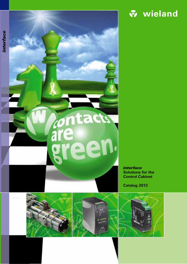
Solutions for the Control Cabinet
Catalog 2013
Industrial technology Solutions for the control cabinet • DIN rail terminal blocks – Screw, tension spring or push-in connection technology – Wire cross sections up to 240 mm2
– Numerous special functions – Software solutions interfacing to CAE systems • Safety – Safe signal acquisition – Safety switching devices – Modular safety modules – Compact safety controllers – Applicative consultancy and training • Network engineering and fi eldbus systems – Remote maintenance via VPN industrial router and VPN service portal – Industrial Ethernet switches – PLC and I/O systems, standard and increased
environmental conditions • Interface – Power supply units – Overvoltage protection – Coupling relays, semiconductor switches – Timer relays, measuring and monitoring relays – Analog coupling and converter modules – Passive interfaces
Solutions for fi eld applications • Decentralized installation and automation technology – Electrical installation for wind tower – Fieldbus interfaces and motor starters • Connectors for industrial applications – Rectangular and round connectors – Aluminum or plastic housings – Degree of protection up to IP 68 – Current-carrying capacity up to 100 A – Connectors for hazardous areas – Modular, application-specifi c technology
PC board terminals and connectors – Screw or spring clamp connection technology – Spacings: 3.5 mm to 10.16 mm – Refl ow or wave soldering process
Building and installation technology • Building installation systems – Main power supply connectors IP 20/IP 65 ... IP 68 – Bus connectors – Low-voltage connectors – Power distribution system with fl at cables – Distribution systems – Bus systems in KNX, LON and radio technology – DIN rail terminal blocks for electrical installations – Overvoltage protection
0800.1 C 11/12
Headquarters:
Wieland Electric GmbH
Brennerstraße 10 – 14
96052 Bamberg, Germany
Sales and Marketing Center:
Wieland Electric GmbH
Benzstraße 9
96052 Bamberg, Germany
Phone +49 951 9324-0
Fax +49 951 9324-198
www.wieland-electric.com
www.gesis.com
automation
building
electronics
22
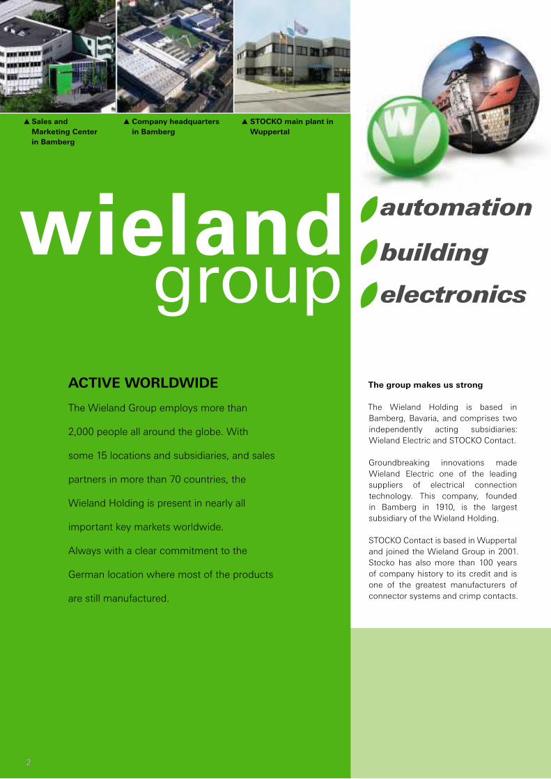
G Company headquarters
in Bamberg
G Sales and
Marketing Center
in Bamberg
G STOCKO main plant in
Wuppertal
The group makes us strong
The Wieland Holding is based in
Bamberg, Bavaria, and comprises two
independently acting subsidiaries:
Wieland Electric and STOCKO Contact.
Groundbreaking innovations made
Wieland Electric one of the leading
suppliers of electrical connection
technology. This company, founded
in Bamberg in 1910, is the largest
subsidiary of the Wieland Holding.
STOCKO Contact is based in Wuppertal
and joined the Wieland Group in 2001.
Stocko has also more than 100 years
of company history to its credit and is
one of the greatest manufacturers of
connector systems and crimp contacts.
The Wieland Group employs more than
2,000 people all around the globe. With
some 15 locations and subsidiaries, and sales
partners in more than 70 countries, the
Wieland Holding is present in nearly all
important key markets worldwide.
Always with a clear commitment to the
German location where most of the products
are still manufactured.
ACTIVE WORLDWIDE

Logistik
3
contacts are green
3
contacts are green
Established in industries
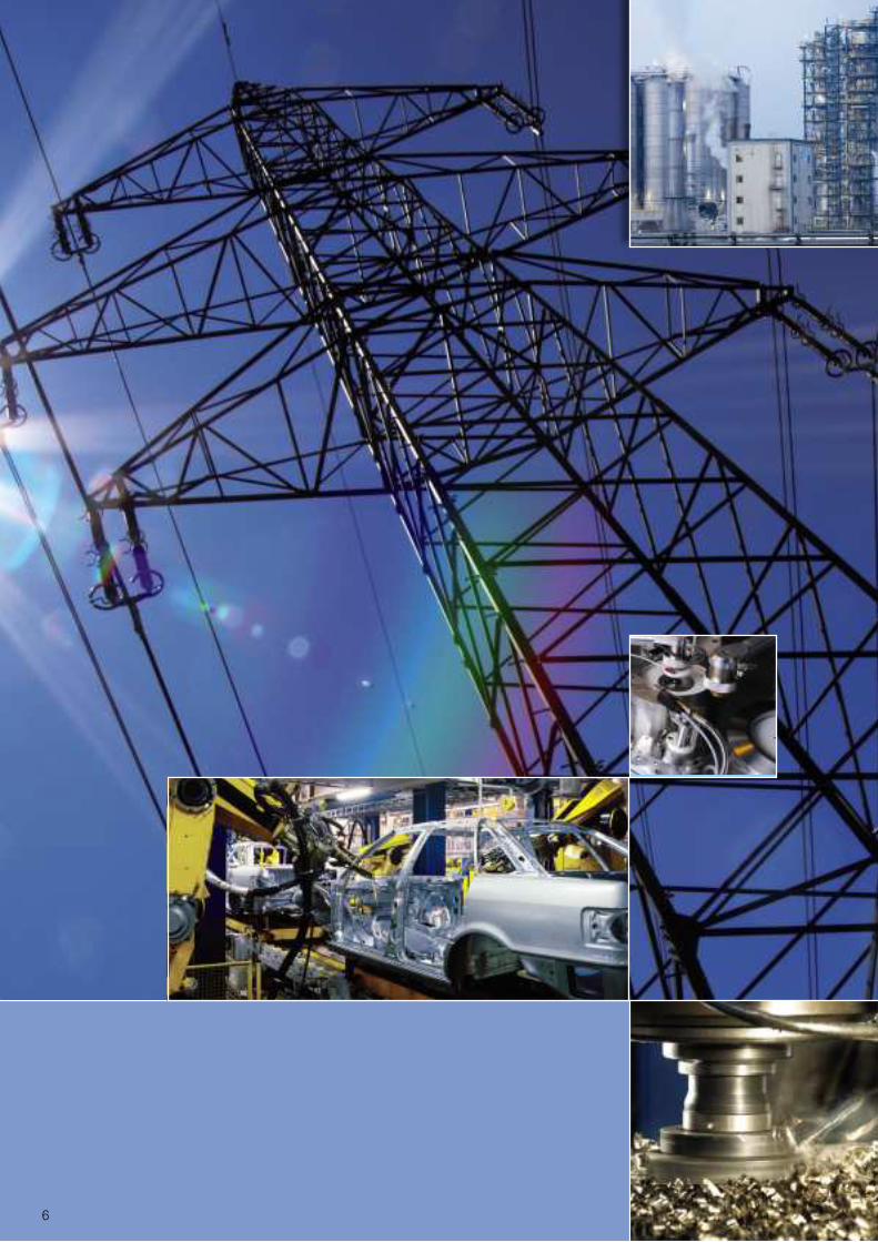
Control cabinet engineering, industrial
automation, building system technology
– our large product portfolio provides
solutions for all kinds of applications.
From innovative interface and net-
work technology to terminal blocks to
"safety first" – with modular system
solutions and safety components.
With Wieland products in your control
cabinet, you are always on the safe side.
Energy bus systems for distributed
automation or indoor and outdoor field
bus components – Wieland technolo-
gy can be found everywhere, and in all
kinds of applications.
In building system technology, Wieland
Electric is the world market leader in
pluggable eletrical installation.
There are good reasons why our
system solutions can be found
in the most spectacular building
projects worldwide. When it comes to
electronic networking, Wieland leads
the way to the “intelligent house”.
Welcome Future
Wieland Electric is 100 years young,
and full of innovative energy. And
our commitment for the future is not
only to find constantly new system
solutions for our customers but also
social responsibility.
Environmentally friendly high-tech
products, manufactured to the la-
test production standards, an audited
environmental management system
and substantial investments in our
locations are all part to this concept.
Global commitment and sustainable
regional action – Wieland Electric is fit
for the future: Contacts are green.

4

LogistikLLLLoooogggggiiiiisssssstttttiiiikkkk
5
contacts are green
ContentsThe Wieland Group 2
interface 6
Signal processing throughout your control
system with our connectivity solutions
Protect 10
wietap overvoltage protection
Supply 38
wipos power supplies
Pure Power – no frills
Coupling 46
wienet / fl are / cores
always the right connection
Control 74
fl are TIME Electronic and electro-
mechanical timer and switching relays
Control with the right setting
Measure and monitor 86
fl are CONTROL Measuring and monitoring relays
The right device for every monitoring task
Additional product lines 92
Safety, DIN rail terminal blocks,
industrial multipole connectors,
cable assemblies, distributed automation
Software Tools 104
Support and consultation 105
Subsidiaries and sales representatives 107
6
interface
7
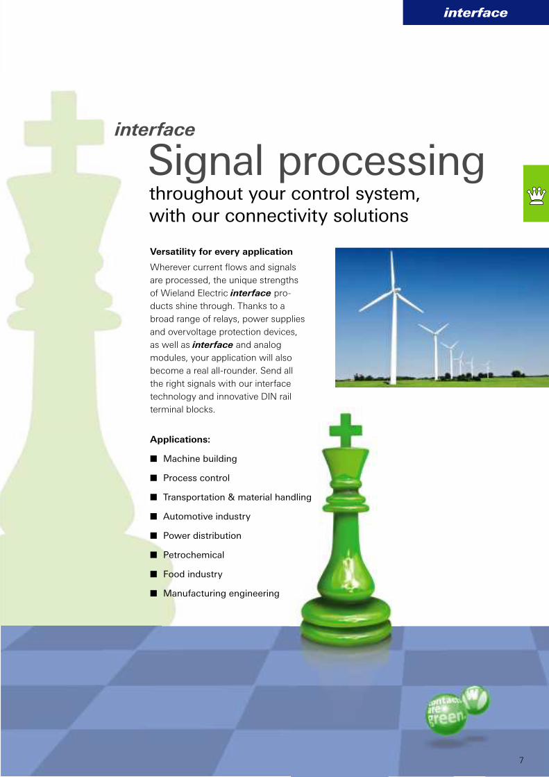
Versatility for every application
Wherever current fl ows and signals
are processed, the unique strengths
of Wieland Electric interface pro-
ducts shine through. Thanks to a
broad range of relays, power supplies
and overvoltage protection devices,
as well as interface and analog
modules, your application will also
become a real all-rounder. Send all
the right signals with our interface
technology and innovative DIN rail
terminal blocks.
interface
Signal processingthroughout your control system,
with our connectivity solutions
Applications:
n Machine building
n Process control
n Transportation & material handling
n Automotive industry
n Power distribution
n Petrochemical
n Food industry
n Manufacturing engineering

8
Signal processing
throughout your control system with our
| protection |wietap overvoltage protection
devices for guaranteed highest
system availability and device
protection
| supply |wipos power supplies including
single-phase and three-phase
devices for DIN rail mounting
in almost any application

interface
9
with our connectivity solutions
| coupling | fl are relays for fl oating coupling
of control functions. Analog
isolation amplifi er cores for
secure coupling. Ethernet switch
series and VPN industrial router
wienet, for communication.
| control |Electronic and electromechanical
timer and multi-function relays fl are TIME
for simple to highly complex control tasks
| measuring and monitoring | Electronic measuring and monitoring
relays fl are CONTROL for all monitoring and
communicating tasks in machines and
systems

10

wietap
wietap
11
Important information on overvoltage
The necessity of overvoltage pro-
tection on machines and systems
as well as for building technology is
ever increasing. The potential danger
of damage and even complete
destruction posed to valuable electro-
nic components or even complete
production systems, computer
systems or communication systems
by sudden overvoltage from the grid,
or direct lightning strikes has mobi-
lized not just insurance companies.
Well-advised users also know the
importance of protecting their electri-
cal devices, plants and systems both
suffi ciently and reliably against this
danger, and the overall advantage of
increasing their system availability.
Overvoltage protection modules
Overvoltage protection modules
come in three type categories which
designate their capacity to absorb
overvoltage energy. Type 1 arresters
can divert the largest amount of
energy to ground (PE). The ideal
installation location for these devices
is at the building’s main supply. In
this confi guration the impulse energy
is considerably weakened, if it moves
downstream into the installation. In
sub-panels and control cabinets, this
surplus energy is reduced further by
type 2 and 3 arresters, thus main-
taining the survival of the protected
devices.
Overvoltage
protection
12
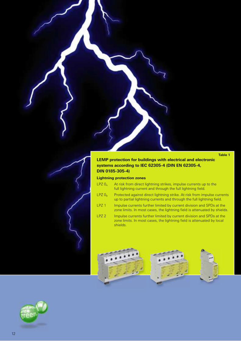
LEMP protection for buildings with electrical and electronic
systems according to IEC 62305-4 (DIN EN 62305-4,
DIN 0185-305-4)
Lightning protection zones
LPZ 0A At risk from direct lightning strikes, impulse currents up to the full lightning current and through the full lightning fi eld.
LPZ 0B Protected against direct lightning strike. At risk from impulse currentsup to partial lightning currents and through the full lightning fi eld.
LPZ 1 Impulse currents further limited by current division and SPDs at thezone limits. In most cases, the lightning fi eld is attenuated by shields.
LPZ 2 Impulse currents further limited by current division and SPDs at thezone limits. In most cases, the lightning fi eld is attenuated by localshields.
Table 1

wietap IEC
13
Very short response time and
high discharge capacity
With its considerably expanded
wietap product range, Wieland
Electric offers comprehensive solu-
tions for overvoltage protection in
control cabinets and sub panels of
machines and buildings, as well as
for photovoltaic systems. The com-
ponents, which are modular and DIN
rail mountable, range from the ready-
to-connect 3-phase combi-arrester
wietap V M for the main distribu-
tion, to the overvoltage protection
module wietap G M for sub panels,
up to the overvoltage module wietap
R M intended for the control cabinet
or constructed into the equipment.
All components are designed for
Playing it safe
application temperatures from -40
to 80 °C and have a high discharge
capacity. Devices are also available
with a remote signaling contact.
Properties of wietap:
n Electrically coordinated
product family
n Highest discharge capacity
up to 100 kA
n No tripping of fuses thanks to
follow current limitation
n Latching pluggable protection
modules
n Vibration and shock tested acc.
to EN 60068-2
n Visual function & defect display
for every path
n Modules replaceable
without tools
n Can also be used in front
of vertical power meter
with overvoltage protection
L1 L2
PEN
L3
✙
4 3
2 1
✙
✙
4 3
2 1
✙
✙✙
R M
2P
255
R M
2P
255
R M
2P
255 F
M
R M
2P
255 F
M
R M
2P
255 F
M
N/PE(N)
L/N
N/PE(N)
L/N
N/PE(N)
L/N
N/PE(N)
R M
2P
255 F
M
R M
2P
255 F
M
R M
2P
255 F
M
L1 L1’
PEN
L2
✙
B3 225 H
N/PE(N)N/PE(N)N/PE(N)
L2’ L3 L3’
25 A25 A
125 A
25 A
125 A
PAS
L1 L2 L3 N PE
1) 1) 1)
1) 1)
315 A 315 A1) 1)
L1 L2 L3 N PE
1234
L1 L1´ L2 L2´
PEN
L3 L3´
✙
V M
TN
C 2
55 F
M
V M
TN
C 2
55 F
M
V M
TN
C 2
55 F
M
315 A1)
L’L
B1 255H
L’L
B1 255H
L’L
B1 255H
L’L
B1 255H
N/PE(N)
L/N
N/PE(N)
L/NL/N
N/PE(N)
R M
2P
255 F
M
R M
2P
255 F
M
R M
2P
255 F
M
L’L
B1 255H
L’L
B1 255H
L’L
B1 255H
14
1) Only necessary when there is no fuse with this or a smaller nominal value in the upstream system.
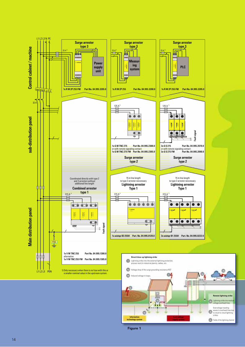
3x wietap B1 255H Part. No. 84.995.0222.01x wietap B3 255H Part. No. 84.995.0120.0
Faul
t sig
nal
1x V M TNC 255 Part No. 84.995.1300.0alternative1x V M TNC 255 FM Part No. 84.995.1305.0
1x R M 2P 255 FM Part No. 84.995.3205.0 1x R M 2P 255 Part No. 84.995.3200.0 1x R M 2P 255 FM Part No. 84.995.3205.0
Faul
t sig
nal
Combined arrestertype 1
Coordinated directly with type 2 and 3 arresters without additional line length
Line length ≥ 5 m
Surge arrestertype 2
Surge arrestertype 2
Mai
n di
strib
utio
n pa
nel
sub-
dist
ribut
ion
pane
lCo
ntro
l cab
inet
/ m
achi
ne
Surge arrestertype 3
Surge arrestertype 3
Surge arrestertype 3
3x G S 275 Part No. 84.995.2070.0or with remote signaling contact:3x G S 275 FM Part No. 84.995.2090.0
1x G M TNC 275 Part No. 84.995.2300.0or with remote signaling contact:1x G M TNC 275 FM Part No. 84.995.2305.0
Power supply
unit
Measur-ing
system PLC
Figure 1
Information technology system
Low-voltage supply system
Remote lightning strike
Lightning strike into medium
voltage overhead lines
Overvoltage traveling
waves in overhead lines due
to cloud-to-cloud lightning
strikes
Fields of the lightning channel
Direct/close-up lightning strike
Lightning strike into the external lightning protection,
process rack (in industrial plants), cables, etc.
Voltage drop of the surge grounding resistance RST
Induced voltage in loops
15 m line length to type 2 arrester neccessary
Lightning arresterType 1
15 m line length to type 2 arrester neccessary
Lightning arresterType 1
wietap IEC
ÀÁ
15
Overvoltage protection
The zone concept for lightning protection
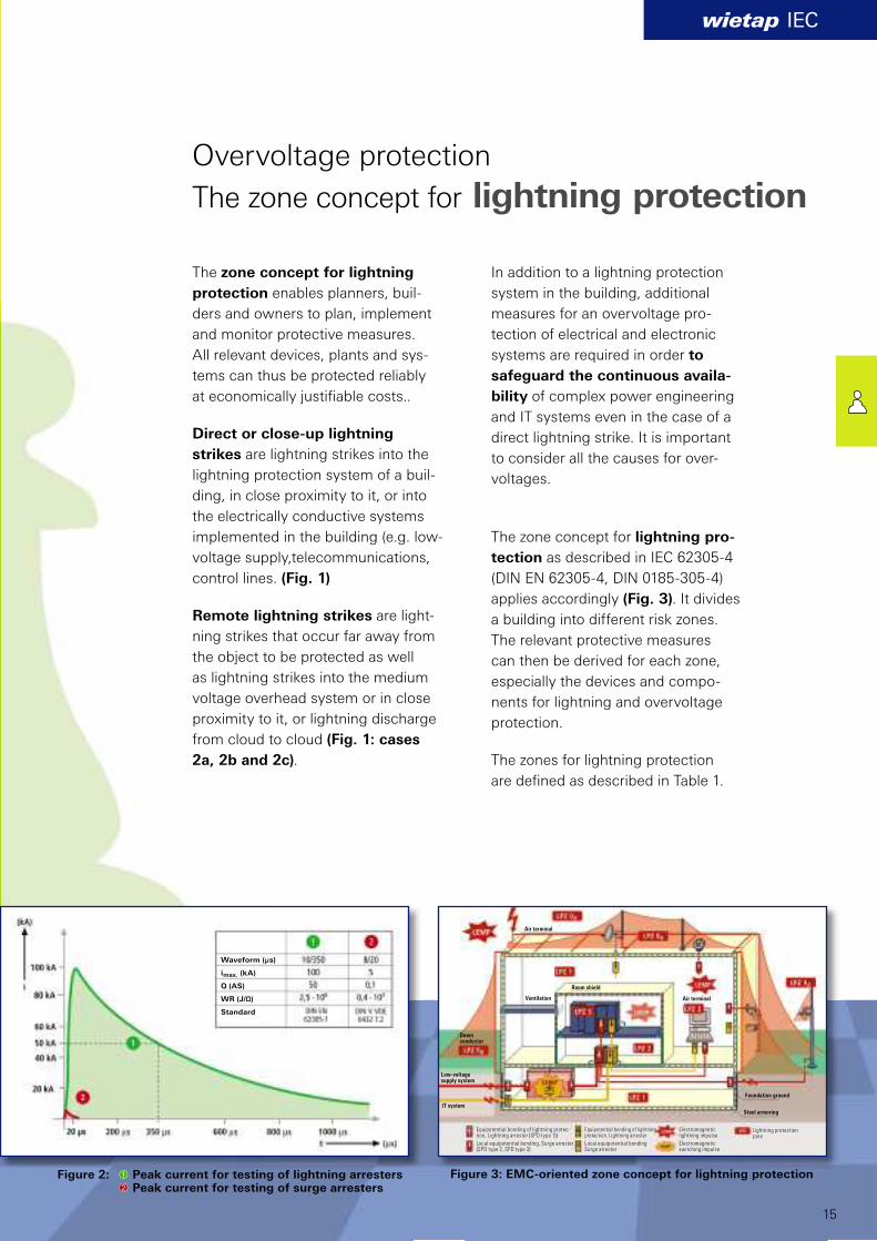
The zone concept for lightning
protection enables planners, buil-
ders and owners to plan, implement
and monitor protective measures.
All relevant devices, plants and sys-
tems can thus be protected reliably
at economically justifi able costs..
Direct or close-up lightning
strikes are lightning strikes into the
lightning protection system of a buil-
ding, in close proximity to it, or into
the electrically conductive systems
implemented in the building (e.g. low-
voltage supply,telecommunications,
control lines. (Fig. 1)
Remote lightning strikes are light-
ning strikes that occur far away from
the object to be protected as well
as lightning strikes into the medium
voltage overhead system or in close
proximity to it, or lightning discharge
from cloud to cloud (Fig. 1: cases
2a, 2b and 2c).
In addition to a lightning protection
system in the building, additional
measures for an overvoltage pro-
tection of electrical and electronic
systems are required in order to
safeguard the continuous availa-
bility of complex power engineering
and IT systems even in the case of a
direct lightning strike. It is important
to consider all the causes for over-
voltages.
The zone concept for lightning pro-
tection as described in IEC 62305-4
(DIN EN 62305-4, DIN 0185-305-4)
applies accordingly (Fig. 3). It divides
a building into different risk zones.
The relevant protective measures
can then be derived for each zone,
especially the devices and compo-
nents for lightning and overvoltage
protection.
The zones for lightning protection
are defi ned as described in Table 1.
Waveform (µs)
imax. (kA)
Q (AS)
WR (J/Ω)
Standard
Figure 3: EMC-oriented zone concept for lightning protection Figure 2: Peak current for testing of lightning arresters Peak current for testing of surge arresters
Equipotential bonding of lightning protec-tion, Lightning arrester (SPD type 1))
Local equipotential bonding, Surge arrester(SPD type 2, SPD type 3)
Air terminal
Ventilation
Room shield
Air terminal
Foundation ground
Steel armoring
Down conductor
Low-voltagesupply system
IT system
Equipotential bonding of lightning protection, Lightning arrester
Local equipotential bondingSurge arrester
Electromagneticlightning impulse
Electromagneticswitching impulse
Lightning protection zone
AöK
AöK
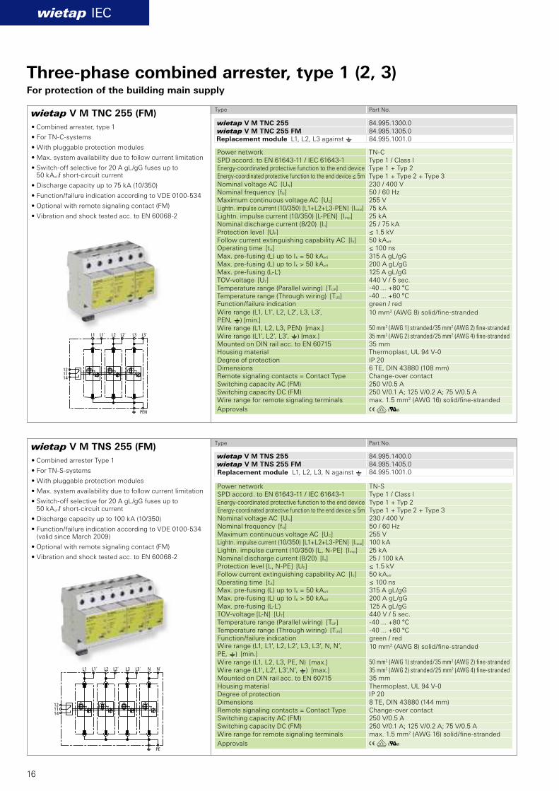
wietap V M TNC 255 (FM)
wietap V M TNS 255 (FM)
wietap IEC
wietap V M TNC 255 84.995.1300.0wietap V M TNC 255 FM 84.995.1305.0
84.995.1001.0
wietap V M TNS 255 84.995.1400.0wietap V M TNS 255 FM 84.995.1405.0
84.995.1001.0
16
• Combined arrester, type 1
• For TN-C-systems
• With pluggable protection modules
• Max. system availability due to follow current limitation
• Switch-off selective for 20 A gL/gG fuses up to50 kAefff short-circuit current
• Discharge capacity up to 75 kA (10/350)
• Function/failure indication according to VDE 0100-534
• Optional with remote signaling contact (FM)
• Vibration and shock tested acc. to EN 60068-2
• Combined arrester Type 1
• For TN-S-systems
• With pluggable protection modules
• Max. system availability due to follow current limitation
• Switch-off selective for 20 A gL/gG fuses up to50 kAefff short-circuit current
• Discharge capacity up to 100 kA (10/350)
• Function/failure indication according to VDE 0100-534 (valid since March 2009)
• Optional with remote signaling contact (FM)
• Vibration and shock tested acc. to EN 60068-2
Type Part No.
Type Part No.
Power network TN-CSPD accord. to EN 61643-11 / IEC 61643-1 Type 1 / Class IEnergy-coordinated protective function to the end device Type 1 + Typ 2Energy-coordinated protective function to the end device ≤ 5m Type 1 + Type 2 + Type 3Nominal voltage AC [UN] 230 / 400 VNominal frequency [fN] 50 / 60 HzMaximum continuous voltage AC [UC] 255 VLightn. impulse current (10/350) [L1+L2+L3-PEN] [Itotal] 75 kALightn. impulse current (10/350) [L-PEN] [Iimp] 25 kANominal discharge current (8/20) [In] 25 / 75 kAProtection level [UP] ≤ 1.5 kVFollow current extinguishing capability AC [Ifi ] 50 kAeff
Operating time [tA] ≤ 100 nsMax. pre-fusing (L) up to IK = 50 kAeff 315 A gL/gGMax. pre-fusing (L) up to IK > 50 kAeff 200 A gL/gGMax. pre-fusing (L-L') 125 A gL/gGTOV-voltage [UT] 440 V / 5 sec.Temperature range (Parallel wiring) [TUP] -40 ... +80 °C
Temperature range (Through wiring) [TUS] -40 ... +60 °C Function/failure indication green / red
Wire range (L1, L1', L2, L2', L3, L3', PEN, e) [min.]
10 mm2 (AWG 8) solid/fi ne-stranded
Wire range (L1, L2, L3, PEN) [max.] 50 mm2 (AWG 1) stranded/35 mm2 (AWG 2) fi ne-stranded
Wire range (L1', L2', L3', e) [max.] 35 mm2 (AWG 2) stranded/25 mm2 (AWG 4) fi ne-stranded
Mounted on DIN rail acc. to EN 60715 35 mm Housing material Thermoplast, UL 94 V-0Degree of protection IP 20 Dimensions 6 TE, DIN 43880 (108 mm)Remote signaling contacts = Contact Type Change-over contactSwitching capacity AC (FM) 250 V/0.5 A Switching capacity DC (FM) 250 V/0.1 A; 125 V/0.2 A; 75 V/0.5 A Wire range for remote signaling terminals max. 1.5 mm2 (AWG 16) solid/fi ne-stranded
Approvals
Power network TN-SSPD accord. to EN 61643-11 / IEC 61643-1 Type 1 / Class IEnergy-coordinated protective function to the end device Type 1 + Typ 2Energy-coordinated protective function to the end device ≤ 5m Type 1 + Type 2 + Type 3Nominal voltage AC [UN] 230 / 400 VNominal frequency [fN] 50 / 60 HzMaximum continuous voltage AC [UC] 255 VLightn. impulse current (10/350) [L1+L2+L3-PEN] [Itotal] 100 kALightn. impulse current (10/350) [L, N-PE] [Iimp] 25 kANominal discharge current (8/20) [In] 25 / 100 kAProtection level [L, N-PE] [UP] ≤ 1.5 kVFollow current extinguishing capability AC [Ifi ] 50 kAeff
Operating time [tA] ≤ 100 nsMax. pre-fusing (L) up to IK = 50 kAeff 315 A gL/gGMax. pre-fusing (L) up to IK > 50 kAeff 200 A gL/gGMax. pre-fusing (L-L') 125 A gL/gGTOV-voltage [L-N] [UT] 440 V / 5 sec.Temperature range (Parallel wiring) [TUP] -40 ... +80 °C Temperature range (Through wiring) [TUS] -40 ... +60 °C Function/failure indication green / redWire range (L1, L1’, L2, L2’, L3, L3’, N, N’, PE, e) [min.]
10 mm2 (AWG 8) solid/fi ne-stranded
Wire range (L1, L2, L3, PE, N) [max.] 50 mm2 (AWG 1) stranded/35 mm2 (AWG 2) fi ne-stranded
Wire range (L1', L2', L3',N’, e) [max.] 35 mm2 (AWG 2) stranded/25 mm2 (AWG 4) fi ne-stranded
Mounted on DIN rail acc. to EN 60715 35 mm Housing material Thermoplast, UL 94 V-0Degree of protection IP 20 Dimensions 8 TE, DIN 43880 (144 mm)Remote signaling contacts = Contact Type Change-over contact Switching capacity AC (FM) 250 V/0.5 A Switching capacity DC (FM) 250 V/0.1 A; 125 V/0.2 A; 75 V/0.5 A Wire range for remote signaling terminals max. 1.5 mm2 (AWG 16) solid/fi ne-stranded
Approvals
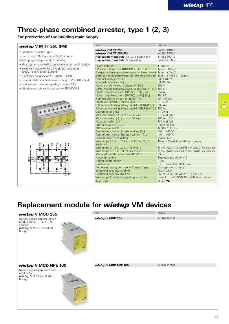
Three-phase combined arrester, type 1 (2, 3)For protection of the building main supply
Replacement module L1, L2, L3 against e
Replacement module L1, L2, L3, N against e
AöK
wietap V M TT 255 (FM)
wietap IEC
wietap V M TT 255 84.995.1310.0wietap V M TT 255 FM 84.995.1315.0
84.995.1001.084.995.1100.0
wietap V MOD 255 84.995.1001.0
wietap V MOD NPE 100 84.995.1100.0
17
• Combined arrester Type 1
• For TT- and TN-S-systems ("3+1" circuits)
• With pluggable protection modules
• Max. system availability due to follow current limitation
• Switch-off selective for 20 A gL/gG fuses up to50 kAefff short-circuit current
• Discharge capacity up to 100 kA (10/350)
• Function/failure indication according to VDE 0100-534
• Optional with remote signaling contact (FM)
• Vibration and shock tested acc. to EN 60068-2
Type Part No.
Type Part No.
Power network TT and TN-SSPD according to EN 61643-11 / IEC 61643-1 Type 1 / Class IEnergy-coordinated protective function to the end device Type 1 + Typ 2Energy-coordinated protective function to the end device ≤ 5m Type 1 + Type 2 + Type 3Nominal voltage AC [UN] 230 / 400 VNominal frequency [fN] 50 / 60 HzMaximum continuous voltage AC [UC] 255 VLightn. impulse current (10/350) [L1+L2+L3 +N-PE] [Itotal] 100 kALightn. impulse current (10/350) [L-N] [Iimp] 25 kALightn. impulse current (10/350) [N-PE] [Iimp] 100 kANominal discharge current (8/20) [In] 25 / 100 kAProtection level [L-N, N-PE] [UP] ≤ 1.5 kVFollow current extinguishing capability [L-N] AC [Ifi ] 50 kAeff
Follow current extinguishing capability [N-PE] AC [Ifi ] 100 Aeff
Operating time [tA] ≤ 100 nsMax. pre-fusing (L) up to IK = 50 kAeff 315 A gL/gGMax. pre-fusing (L) up to IK > 50 kAeff 200 A gL/gGMax. pre-fusing (L-L') 125 A gL/gGTOV-voltage [L-N] [UT] 440 V / 5 sec.TOV-voltage [N-PE] [UT] 1200 V / 200 msTemperature range (Parallel wiring) [TUP] -40 ... +80 °C Temperature range (Through wiring) [TUS] -40 ... +60 °C Function/failure indication green / redWire range (L1, L1', L2, L2', L3, L3', N, N', PE, e) [min.]
10 mm2 (AWG 8) solid/fi ne-stranded
Wire range (L1, L2, L3, N, PE) [max.] 50 mm2 (AWG 1) stranded/35 mm2 (AWG 2) fi ne-stranded
Wire range (L1', L2', L3', N, e) [max.] 35 mm2 (AWG 2) stranded/25 mm2 (AWG 4) fi ne-stranded
Mounted on DIN rail acc. to EN 60715 35 mm Housing material Thermoplast, UL 94 V-0Degree of protection IP 20 Dimensions 8 TE, DIN 43880 (144 mm)Remote signaling contacts = Contact Type Change-over contact Switching capacity AC (FM) 250 V/0.5 A Switching capacity DC (FM) 250 V/0.1 A; 125 V/0.2 A; 75 V/0.5 AWire range for remote signaling terminals max. 1.5 mm2 (AWG 16) solid/fi ne-stranded
Approvals
Three-phase combined arrester, type 1 (2, 3)For protection of the building main supply
Replacement module L1, L2, L3 against NReplacement module N against e
wietap V MOD NPE 100Network spark gap protection module for wietap V M TT 255 (FM)N – e
wietap V MOD 255Network spark gap protection module for all L – e; L – N and for wietap V M TNS 255 (FM) N – e
Replacement module for wietap VM devices

Aö
Aö
wietap B1 255H
wietap B3 255H
wietap IEC
N/PEN
L1 L2 L3
wietap B3 255H 84.995.0120.0
wietap B1 255H 84.995.0222.0
N/PENN´/PEN
L L´
18
Type Part No.
Type Part No.
• Lightning arrester, type 1
• For all systems (in connection with wietap GPM 255 if required)
• High limitation of follow current
• 50 kA discharge capacity per pole
• High insulation resistance; can therefore also be placed in front of the meter
• Double terminals for V connection
Technical Data SPD accord. to EN 61643-11 Type 1 SPD accord. to IEC 61643-1 Class I Nominal voltage AC [UN] 230/400 V Maximum continuous voltage AC [UC] 255 V Lightn. impulse current (10/350) [L-N/PEN] [Iimp] 50 kA Lightn. impulse current (10/350) [L1+L2+L3-N/PEN] [Itotal]
100 kA
Nominal discharge current (8/20) [In] 50 / 100 kA Protection level [UP] ≤ 4 kV Follow current extinguishing capability AC [Ifi ] 50 kAeff Limitation of follow current / selectivity Non-tripping of a 35 A gL/gG fuse
up to 50 kAeff (prosp.) Operating time [tA] ≤ 100 ns Max. pre-fusing bis IK = 50 kAeff (ta ≤ 0,2 s) 500 A gL/gG Max. pre-fusing bis IK = 50 kAeff (ta ≤ 5 s) 315 A gL/gG Max. pre-fusing bei IK > 50 kAeff 200 A gL/gG Max. pre-fusing (L-L ) 125 A gL/gG TOV-voltage [UT] 335 V / 5 sec. Temperature range (Parallel wiring) [TUP] -40 ... +80 °C
Temperature range (Through wiring) [TUS] -40 ... +60 °C
Wire range (L1, L1 , L2, L2 , L3, L3 , N/PEN, N /PEN)
10 mm² (AWG 8) solid/fi ne-stranded
Wire range (L1, L2, L3, N/PEN) 50 mm² (AWG 1) stranded /35 mm² (AWG 2) fi ne-stranded
Wire range (L1 , L2 , L3 , N /PEN) 35 mm² (AWG 2) stranded /25 mm² (AWG 4) fi ne-stranded
Mounted on DIN rail acc. to EN 60715 35 mmHousing material Thermoplast, UL 94 V-0Degree of protection IP 20 Dimensions 6 TE, DIN 43880 (108 mm)
Approvals
Technical Data SPD accord. to EN 61643-11 Type 1 SPD accord. to IEC 61643-1 Class I Nominal voltage ac [UN] 230 V Maximum continuous voltage AC [UC] 255 V Lightn. impulse current (10/350) [Iimp] 50 kA Nominal discharge current (8/20) [In] 50 kA Protection level [UP] ≤ 4 kV Follow current extinguishing capability AC [Ifi ] 50 kAeff Limitation of follow current / selectivity Non-tripping of a 35 A gL/gG fuse
up to 50 kAeff (prosp.) Operating time [tA] ≤ 100 ns Max. pre-fusing bis IK = 50 kAeff (ta ≤ 0,2 s) 500 A gL/gG Max. pre-fusing bis IK = 50 kAeff (ta ≤ 5 s) 315 A gL/gG Max. pre-fusing bei IK > 50 kAeff 200 A gL/gG Max. pre-fusing (L-L ) 125 A gL/gG TOV-voltage [UT] 335 V / 5 sec.
Temperature range (Parallel wiring) [TUP] -40 ... +80 °C
Temperature range (Through wiring) [TUS] -40 ... +60 °C
Wire range (L, L , N/PEN, N /PEN) [min.] 10 mm² (AWG 8) solid/fi ne-stranded
Wire range (L, N/PEN) [max.] 50 mm² (AWG 1) stranded /35 mm² (AWG 2) fi ne-stranded
Wire range (L , N /PEN) [max.] 35 mm² (AWG 2) stranded /25 mm² (AWG 4) fi ne-stranded
Mounted on DIN rail acc. to EN 60715 35 mmHousing material Thermoplast, UL 94 V-0Degree of protection IP 20 Dimensions 2 TE, DIN 43880 (36 mm)
Approvals
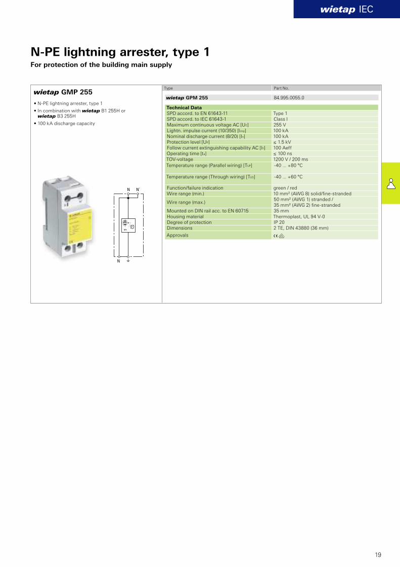
3-phase lightning arrester, type 1For protection of the building main supply
1-phase lightning arrester, type 1For the protection of the building main supply
• Lightning arrester, type 1
• For all systems (in connection with wietap GPM 255 if required)
• High limitation of follow current
• 50 kA discharge capacity per pole
• High insulation resistance; can therefore also be placed in front of the meter
• Double terminals for V connection
Aö
wietap GMP 255
wietap IEC
N N´
N
NPE
wietap GPM 255 84.995.0055.0
19
Type Part No.
Technical Data SPD accord. to EN 61643-11 Type 1 SPD accord. to IEC 61643-1 Class I Maximum continuous voltage AC [UC] 255 V Lightn. impulse current (10/350) [limp] 100 kA Nominal discharge current (8/20) [In] 100 kA Protection level [UP] ≤ 1.5 kV Follow current extinguishing capability AC [lfi ] 100 Aeff Operating time [ta] ≤ 100 ns TOV-voltage 1200 V / 200 ms
Temperature range (Parallel wiring) [TUP] -40 ... +80 °C
Temperature range (Through wiring) [TUS] -40 ... +60 °C
Function/failure indication green / red Wire range (min.) 10 mm² (AWG 8) solid/fi ne-stranded
Wire range (max.) 50 mm² (AWG 1) stranded /35 mm² (AWG 2) fi ne-stranded
Mounted on DIN rail acc. to EN 60715 35 mmHousing material Thermoplast, UL 94 V-0Degree of protection IP 20 Dimensions 2 TE, DIN 43880 (36 mm)
Approvals
N-PE lightning arrester, type 1For protection of the building main supply
• N-PE lightning arrester, type 1
• In combination with wietap B1 255H or wietap B3 255H
• 100 kA discharge capacity
AöK
AöK
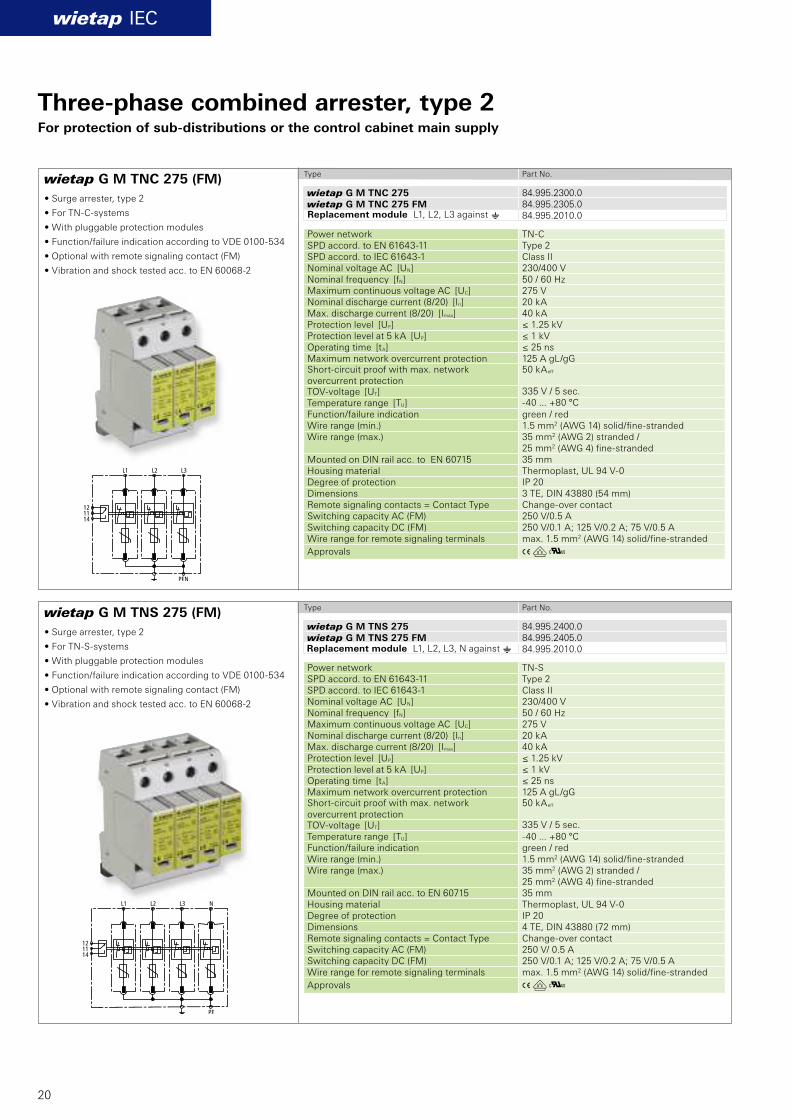
wietap G M TNC 275 (FM)
wietap G M TNS 275 (FM)
wietap IEC
wietap G M TNC 275 84.995.2300.0wietap G M TNC 275 FM 84.995.2305.0
84.995.2010.0
wietap G M TNS 275 84.995.2400.0wietap G M TNS 275 FM 84.995.2405.0
84.995.2010.0
20
Three-phase combined arrester, type 2For protection of sub-distributions or the control cabinet main supply
• Surge arrester, type 2
• For TN-C-systems
• With pluggable protection modules
• Function/failure indication according to VDE 0100-534
• Optional with remote signaling contact (FM)
• Vibration and shock tested acc. to EN 60068-2
• Surge arrester, type 2
• For TN-S-systems
• With pluggable protection modules
• Function/failure indication according to VDE 0100-534
• Optional with remote signaling contact (FM)
• Vibration and shock tested acc. to EN 60068-2
Type Part No.
Type Part No.
Power network TN-CSPD accord. to EN 61643-11 Type 2 SPD accord. to IEC 61643-1 Class II Nominal voltage AC [UN] 230/400 V Nominal frequency [fN] 50 / 60 HzMaximum continuous voltage AC [UC] 275 V Nominal discharge current (8/20) [In] 20 kA Max. discharge current (8/20) [Imax] 40 kA Protection level [UP] ≤ 1.25 kV Protection level at 5 kA [UP] ≤ 1 kV Operating time [tA] ≤ 25 ns Maximum network overcurrent protection 125 A gL/gG Short-circuit proof with max. network overcurrent protection
50 kAeff
TOV-voltage [UT] 335 V / 5 sec.
Temperature range [TU] -40 ... +80 °C
Function/failure indication green / red Wire range (min.) 1.5 mm2 (AWG 14) solid/fi ne-stranded Wire range (max.) 35 mm2 (AWG 2) stranded /
25 mm2 (AWG 4) fi ne-stranded Mounted on DIN rail acc. to EN 60715 35 mm Housing material Thermoplast, UL 94 V-0Degree of protection IP 20 Dimensions 3 TE, DIN 43880 (54 mm)Remote signaling contacts = Contact Type Change-over contact Switching capacity AC (FM) 250 V/0.5 A Switching capacity DC (FM) 250 V/0.1 A; 125 V/0.2 A; 75 V/0.5 A Wire range for remote signaling terminals max. 1.5 mm2 (AWG 14) solid/fi ne-stranded
Approvals
Power network TN-SSPD accord. to EN 61643-11 Type 2 SPD accord. to IEC 61643-1 Class II Nominal voltage AC [UN] 230/400 V Nominal frequency [fN] 50 / 60 HzMaximum continuous voltage AC [UC] 275 V Nominal discharge current (8/20) [In] 20 kA Max. discharge current (8/20) [Imax] 40 kA Protection level [UP] ≤ 1.25 kV Protection level at 5 kA [UP] ≤ 1 kV Operating time [tA] ≤ 25 ns Maximum network overcurrent protection 125 A gL/gG Short-circuit proof with max. network overcurrent protection
50 kAeff
TOV-voltage [UT] 335 V / 5 sec.
Temperature range [TU] -40 ... +80 °C Function/failure indication green / red Wire range (min.) 1.5 mm2 (AWG 14) solid/fi ne-stranded Wire range (max.) 35 mm2 (AWG 2) stranded /
25 mm2 (AWG 4) fi ne-stranded Mounted on DIN rail acc. to EN 60715 35 mm Housing material Thermoplast, UL 94 V-0Degree of protection IP 20 Dimensions 4 TE, DIN 43880 (72 mm)Remote signaling contacts = Contact Type Change-over contact Switching capacity AC (FM) 250 V/ 0.5 A Switching capacity DC (FM) 250 V/0.1 A; 125 V/0.2 A; 75 V/0.5 A Wire range for remote signaling terminals max. 1.5 mm2 (AWG 14) solid/fi ne-stranded
Approvals
Replacement module L1, L2, L3 against e
Replacement module L1, L2, L3, N against e
AöK
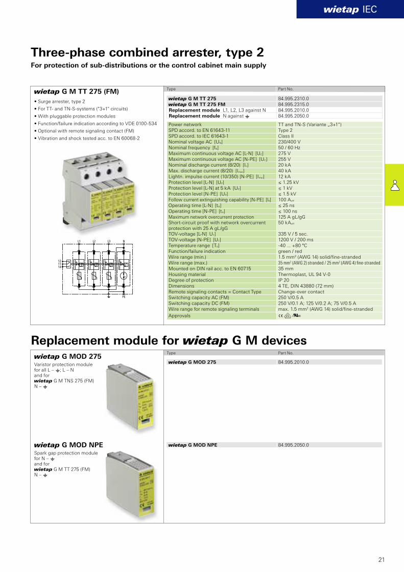
wietap G M TT 275 (FM)
wietap IEC
wietap G M TT 275 84.995.2310.0wietap G M TT 275 FM 84.995.2315.0
84.995.2010.084.995.2050.0
wietap G MOD 275 84.995.2010.0
wietap G MOD NPE 84.995.2050.0
21
Three-phase combined arrester, type 2For protection of sub-distributions or the control cabinet main supply
• Surge arrester, type 2
• For TT- and TN-S-systems ("3+1" circuits)
• With pluggable protection modules
• Function/failure indication according to VDE 0100-534
• Optional with remote signaling contact (FM)
• Vibration and shock tested acc. to EN 60068-2
Type Part No.
Type Part No.
Power network TT and TN-S (Variante „3+1“)SPD accord. to EN 61643-11 Type 2 SPD accord. to IEC 61643-1 Class II Nominal voltage AC [UN] 230/400 V Nominal frequency [fN] 50 / 60 HzMaximum continuous voltage AC [L-N] [UC] 275 V Maximum continuous voltage AC [N-PE] [UC] 255 V Nominal discharge current (8/20) [In] 20 kA Max. discharge current (8/20) [Imax] 40 kA Lightn. impulse current (10/350) [N-PE] [Iimp] 12 kA Protection level [L-N] [UP] ≤ 1.25 kV Protection level [L-N] at 5 kA [UP] ≤ 1 kV Protection level [N-PE] [UP] ≤ 1.5 kV Follow current extinguishing capability [N-PE] [Ifi ] 100 Aeff Operating time [L-N] [tA] ≤ 25 ns Operating time [N-PE] [tA] ≤ 100 ns Maximum network overcurrent protection 125 A gL/gG Short-circuit proof with network overcurrentprotection with 25 A gL/gG
50 kAeff
TOV-voltage [L-N] UT] 335 V / 5 sec. TOV-voltage [N-PE] [UT] 1200 V / 200 ms Temperature range [TU] -40 ... +80 °C Function/failure indication green / red Wire range (min.) 1.5 mm2 (AWG 14) solid/fi ne-stranded Wire range (max.) 35 mm2 (AWG 2) stranded / 25 mm2 (AWG 4) fi ne-stranded
Mounted on DIN rail acc. to EN 60715 35 mm Housing material Thermoplast, UL 94 V-0Degree of protection IP 20 Dimensions 4 TE, DIN 43880 (72 mm)Remote signaling contacts = Contact Type Change-over contact Switching capacity AC (FM) 250 V/0.5 A Switching capacity DC (FM) 250 V/0.1 A; 125 V/0.2 A; 75 V/0.5 A Wire range for remote signaling terminals max. 1.5 mm2 (AWG 14) solid/fi ne-stranded
Approvals
wietap G MOD NPE Spark gap protection module for N – eand for wietap G M TT 275 (FM)N – e
wietap G MOD 275Varistor protection module for all L – e; L – N and for wietap G M TNS 275 (FM)N – e
Replacement module L1, L2, L3 against NReplacement module N against e
Replacement module for wietap G M devices
AöK
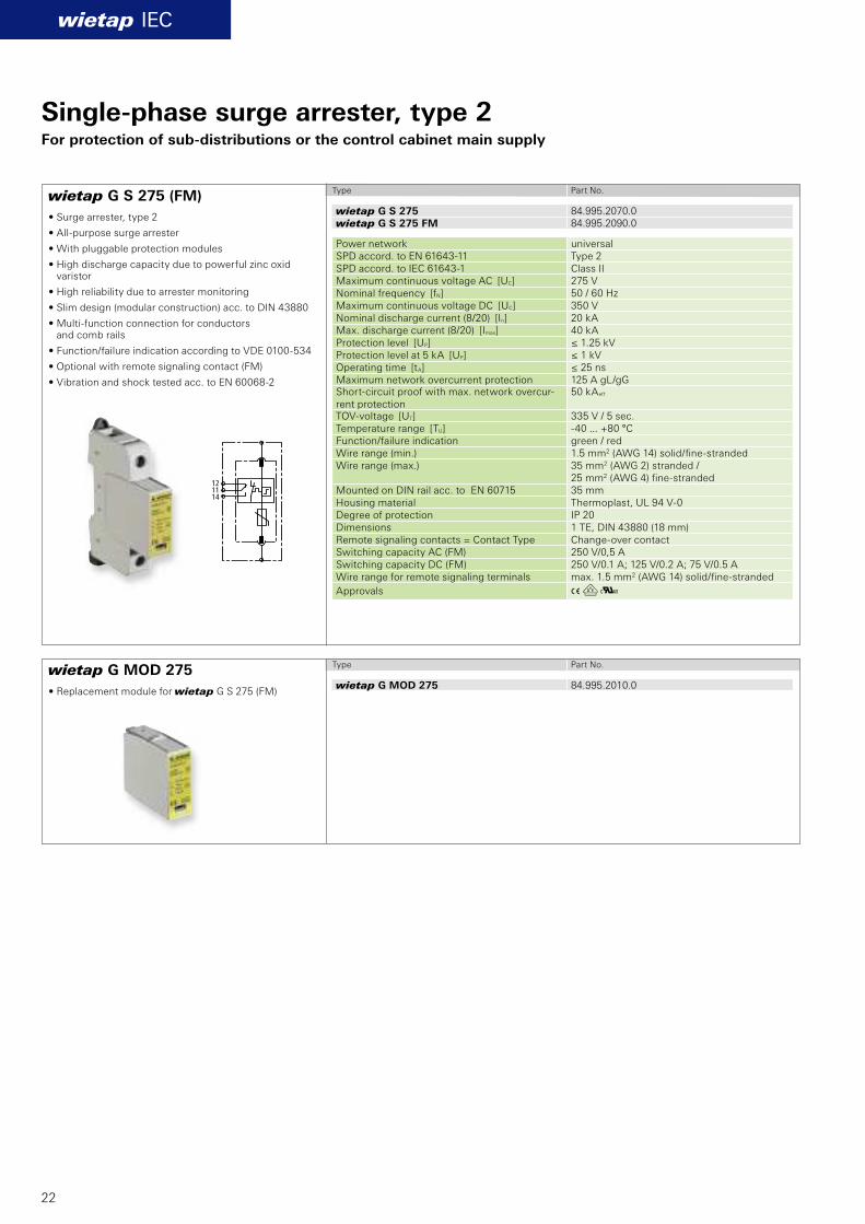
wietap G S 275 (FM)
wietap G MOD 275
wietap IEC
wietap G S 275 84.995.2070.0wietap G S 275 FM 84.995.2090.0
wietap G MOD 275 84.995.2010.0
22
Single-phase surge arrester, type 2For protection of sub-distributions or the control cabinet main supply
Type Part No.
• Surge arrester, type 2
• All-purpose surge arrester
• With pluggable protection modules
• High discharge capacity due to powerful zinc oxidvaristor
• High reliability due to arrester monitoring
• Slim design (modular construction) acc. to DIN 43880
• Multi-function connection for conductors and comb rails
• Function/failure indication according to VDE 0100-534
• Optional with remote signaling contact (FM)
• Vibration and shock tested acc. to EN 60068-2
Type Part No.
• Replacement module for wietap G S 275 (FM)
Power network universalSPD accord. to EN 61643-11 Type 2 SPD accord. to IEC 61643-1 Class II Maximum continuous voltage AC [UC] 275 V Nominal frequency [fN] 50 / 60 HzMaximum continuous voltage DC [UC] 350 V Nominal discharge current (8/20) [In] 20 kA Max. discharge current (8/20) [Imax] 40 kA Protection level [UP] ≤ 1.25 kV Protection level at 5 kA [UP] ≤ 1 kV Operating time [tA] ≤ 25 ns Maximum network overcurrent protection 125 A gL/gG Short-circuit proof with max. network overcur-rent protection
50 kAeff
TOV-voltage [UT] 335 V / 5 sec. Temperature range [TU] -40 ... +80 °C Function/failure indication green / red Wire range (min.) 1.5 mm2 (AWG 14) solid/fi ne-stranded Wire range (max.) 35 mm2 (AWG 2) stranded /
25 mm2 (AWG 4) fi ne-stranded Mounted on DIN rail acc. to EN 60715 35 mm Housing material Thermoplast, UL 94 V-0Degree of protection IP 20 Dimensions 1 TE, DIN 43880 (18 mm)Remote signaling contacts = Contact Type Change-over contact Switching capacity AC (FM) 250 V/0,5 A Switching capacity DC (FM) 250 V/0.1 A; 125 V/0.2 A; 75 V/0.5 A Wire range for remote signaling terminals max. 1.5 mm2 (AWG 14) solid/fi ne-stranded
Approvals
AöK
wietap GP C S (FM)
wietap GP C MOD
wietap IEC
wietap GP C S 84.995.2030.0wietap GP C S FM 84.995.2035.0
wietap GP C MOD 84.995.2060.0
23
Single-phase surge arrester, type 2For protection of sub-distributions or the control cabinet main supply
Type Part No.
• Surge arrester, type 2
• For use in TT systems in "3+1" and "1+1" circuits acc. to E DIN VDE 0100-534 between neutral conductor N and protective conductor PE
• High discharge capacity
• With pluggable protection modules
• Function/failure indication according to VDE 0100-534
• Optional with remote signaling contact (FM)
• Vibration and shock tested acc. to EN 60068-2
• Replacement module for wietap G CS (FM)
Type Part No.
Power network TTSPD accord. to EN 61643-11 Type 2 SPD accord. to IEC 61643-1 Class II Maximum continuous voltage AC [UC] 255 V Nominal frequency [fN] 50 / 60 HzNominal discharge current (8/20) [In] 20 kA Max. discharge current (8/20) [Imax] 40 kA Follow current extinguishing capability [Ifi ] 100 Aeff Lightn. impulse current (10/350) [Iimp] 12 kA Protection level [UP] ≤ 1.5 kV Operating time [tA] ≤ 100 ns TOV-voltage [UT] 1200 V / 200 ms Temperature range [TU] -40 ... +80 °C Function/failure indication green / red Wire range (min.) 1.5 mm2 (AWG 14) solid/fi ne-stranded Wire range (max.) 35 mm2 (AWG 2) stranded /
25 mm2 (AWG 4) fi ne-stranded Mounted on DIN rail acc. to EN 60715 35 mm Housing material Thermoplast, UL 94 V-0Degree of protection IP 20 Dimensions 1 TE, DIN 43880 (18 mm)Remote signaling contacts = Contact Type Change-over contact Switching capacity AC(FM) 250 V/0.5 A Switching capacity DC (FM) 250 V/0.1 A; 125 V/0.2 A; 75 V/0.5 A Wire range for remote signaling terminals max. 1.5 mm2 (AWG 14) solid/fi ne-stranded
Approvals
AöKw
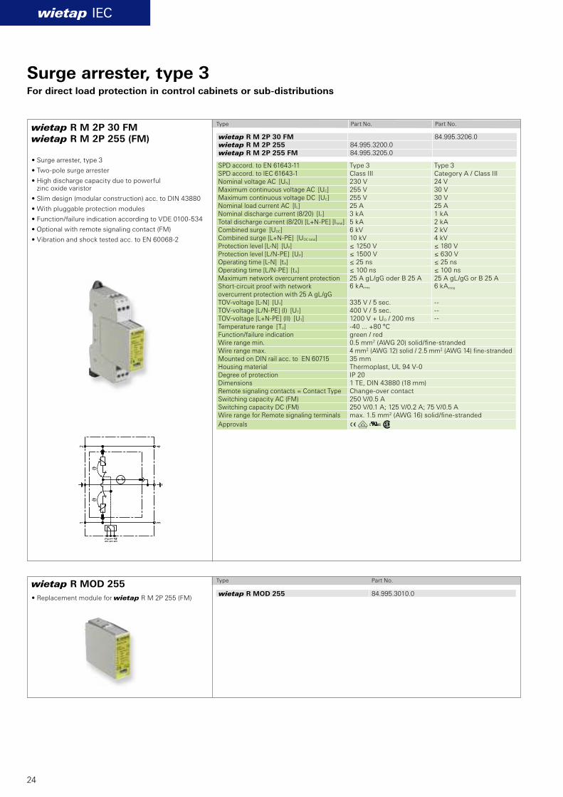
wietap R M 2P 30 FM wietap R M 2P 255 (FM)
wietap R MOD 255
wietap IEC
wietap R M 2P 30 FM 84.995.3206.0wietap R M 2P 255 84.995.3200.0wietap R M 2P 255 FM 84.995.3205.0
wietap R MOD 255 84.995.3010.0
24
Surge arrester, type 3For direct load protection in control cabinets or sub-distributions
Type Part No. Part No.
• Surge arrester, type 3
• Two-pole surge arrester
• High discharge capacity due to powerful zinc oxide varistor
• Slim design (modular construction) acc. to DIN 43880
• With pluggable protection modules
• Function/failure indication according to VDE 0100-534
• Optional with remote signaling contact (FM)
• Vibration and shock tested acc. to EN 60068-2
• Replacement module for wietap R M 2P 255 (FM)
Type Part No.
SPD accord. to EN 61643-11 Type 3 Type 3 SPD accord. to IEC 61643-1 Class III Category A / Class III Nominal voltage AC [UN] 230 V 24 V Maximum continuous voltage AC [UC] 255 V 30 V Maximum continuous voltage DC [UC] 255 V 30 V Nominal load current AC [IL] 25 A 25 A Nominal discharge current (8/20) [In] 3 kA 1 kA Total discharge current (8/20) [L+N-PE] [Itotal] 5 kA 2 kA Combined surge [UOC] 6 kV 2 kV Combined surge [L+N-PE] [UOC total] 10 kV 4 kV Protection level [L-N] [UP] ≤ 1250 V ≤ 180 V Protection level [L/N-PE] [UP] ≤ 1500 V ≤ 630 V Operating time [L-N] [tA] ≤ 25 ns ≤ 25 ns Operating time [L/N-PE] [tA] ≤ 100 ns ≤ 100 ns Maximum network overcurrent protection 25 A gL/gG oder B 25 A 25 A gL/gG or B 25 A Short-circuit proof with network overcurrent protection with 25 A gL/gG
6 kA rms 6 kArms
TOV-voltage [L-N] [UT] 335 V / 5 sec. -- TOV-voltage [L/N-PE] (I) [UT] 400 V / 5 sec. -- TOV-voltage [L+N-PE] (II) [UT] 1200 V + UO / 200 ms -- Temperature range [TU] -40 ... +80 °C Function/failure indication green / red Wire range min. 0.5 mm2 (AWG 20) solid/fi ne-stranded Wire range max. 4 mm2 (AWG 12) solid / 2.5 mm2 (AWG 14) fi ne-stranded Mounted on DIN rail acc. to EN 60715 35 mm Housing material Thermoplast, UL 94 V-0Degree of protection IP 20 Dimensions 1 TE, DIN 43880 (18 mm)Remote signaling contacts = Contact Type Change-over contact Switching capacity AC (FM) 250 V/0.5 A Switching capacity DC (FM) 250 V/0.1 A; 125 V/0.2 A; 75 V/0.5 A Wire range for Remote signaling terminals max. 1.5 mm2 (AWG 16) solid/fi ne-stranded
Approvals

AöK
wietap R M 4P 255 (FM)
wietap R M MOD 4P 255
wietap IEC
L1 L1 L2 L2
N N
ϑ
L3 L3
121114
PE PE
ϑϑ
wietap R M 4P 255 84.995.3400.0wietap R M 4P 255 FM 84.995.3405.0
wietap R M MOD 4P 255 84.995.3020.0
25
Surge arrester, type 3For direct load protection in control cabinets or sub-distributions
Type Part No.
• Surge arrester, type 3
• Four-pole surge arrester
• High discharge capacity due to powerful zinc oxide varistor
• Slim design (modular construction) acc. to DIN 43880
• With pluggable protection modules
• Function/failure indication according to VDE 0100-534
• Optional with remote signaling contact (FM)
• Vibration and shock tested acc. to EN 60068-2
Technical Data SPD accord. to EN 61643-11 Type 3 SPD accord. to IEC 61643-1 Class III Nominal voltage AC [UN] 230/400 V Maximum continuous voltage AC [UC] 255/440 V Nominal load current AC [IL] 25 A Nominal discharge current (8/20) [In] 3 kA Total discharge current (8/20) [L+N-PE] [Itotal] 8 kA Combined surge [UOC] 6 kV Combined surge [L+N-PE] [UOC total] 16 kV Protection level [L-N] [UP] ≤ 1000 V Protection level [L/N-PE] [UP] ≤ 1500 V Operating time [L-N] [tA] ≤ 25 ns Operating time [L/N-PE] [tA] ≤ 100 ns Maximum network overcurrent protection 25 A gL/gG oder B 25 A Short-circuit proof with network overcurrentprotection with 25 A gL/gG
6 kAeff
TOV-voltage [L-N] [UT] 335 V / 5 sec. TOV-voltage [L/N-PE] (I) [UT] 400 V / 5 sec. TOV-voltage [L+N-PE] (II) [UT] 1200 V + U0 / 200 ms Temperature range [TU] -40 ... +80 °C Function/failure indication green / red Wire range (min.) 0.5 mm² (AWG 20) solid/fi ne-stranded Wire range (max.) 4 mm² (AWG 12) solid /
2.5 mm² (AWG 14) fi ne-stranded Mounted on DIN rail acc. to EN 60715 35 mmHousingwerkstoff Thermoplast, UL 94 V-0Degree of protection IP 20 Dimensions 2 TE, DIN 43880 (36 mm) Remote signaling contacts = Contact Type Change-over contact Switching capacity AC (FM) 250 V/0.5 A Switching capacity DC (FM) 250 V/0.1 A; 125 V/0.2 A; 75 V/0.5 AWire range for remote signaling terminals max. 1.5 mm2 (AWG 16) solid/fine-stranded
Approvals
• Replacement module for wietap R M 4P 255
Type Part No.
26
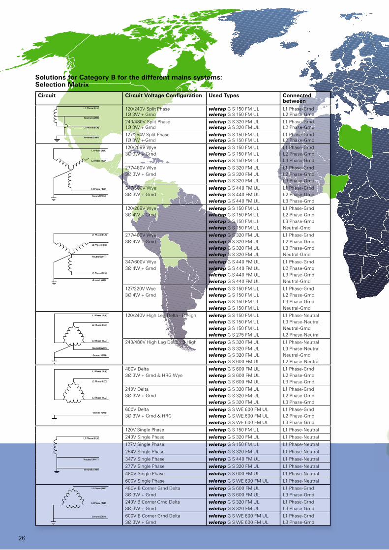
120/240V Split Phase 1Ø 3W + Grnd
wietap G S 150 FM ULwietap G S 150 FM UL
L1 Phase-GrndL2 Phase-Grnd
240/480V Split Phase1Ø 3W + Grnd
wietap G S 320 FM ULwietap G S 320 FM UL
L1 Phase-GrndL2 Phase-Grnd
127/254V Split Phase1Ø 3W + Grnd
wietap G S 150 FM ULwietap G S 150 FM UL
L1 Phase-GrndL2 Phase-Grnd
120/208V Wye
3Ø 3W + Grnd
wietap G S 150 FM UL
wietap G S 150 FM UL
wietap G S 150 FM UL
L1 Phase-Grnd
L2 Phase-Grnd
L3 Phase-Grnd
277/480V Wye
3Ø 3W + Grnd
wietap G S 320 FM UL
wietap G S 320 FM UL
wietap G S 320 FM UL
L1 Phase-Grnd
L2 Phase-Grnd
L3 Phase-Grnd
347/600V Wye
3Ø 3W + Grnd
wietap G S 440 FM UL
wietap G S 440 FM UL
wietap G S 440 FM UL
L1 Phase-Grnd
L2 Phase-Grnd
L3 Phase-Grnd
120/208V Wye
3Ø 4W + Grnd
wietap G S 150 FM UL
wietap G S 150 FM UL
wietap G S 150 FM UL
wietap G S 150 FM UL
L1 Phase-Grnd
L2 Phase-Grnd
L3 Phase-Grnd
Neutral-Grnd
277/480V Wye
3Ø 4W + Grnd
wietap G S 320 FM UL
wietap G S 320 FM UL
wietap G S 320 FM UL
wietap G S 320 FM UL
L1 Phase-Grnd
L2 Phase-Grnd
L3 Phase-Grnd
Neutral-Grnd
347/600V Wye
3Ø 4W + Grnd
wietap G S 440 FM UL
wietap G S 440 FM UL
wietap G S 440 FM UL
wietap G S 440 FM UL
L1 Phase-Grnd
L2 Phase-Grnd
L3 Phase-Grnd
Neutral-Grnd
127/220V Wye
3Ø 4W + Grnd
wietap G S 150 FM UL
wietap G S 150 FM UL
wietap G S 150 FM UL
wietap G S 150 FM UL
L1 Phase-Grnd
L2 Phase-Grnd
L3 Phase-Grnd
Neutral-Grnd
120/240V High Leg Delta - B High wietap G S 150 FM UL
wietap G S 150 FM UL
wietap G S 150 FM UL
wietap G S 275 FM UL
L1 Phase-Neutral
L3 Phase-Neutral
Neutral-Grnd
L2 Phase-Neutral
240/480V High Leg Delta - B High wietap G S 320 FM UL
wietap G S 320 FM UL
wietap G S 320 FM UL
wietap G S 600 FM UL
L1 Phase-Neutral
L3 Phase-Neutral
Neutral-Grnd
L2 Phase-Neutral
480V Delta
3Ø 3W + Grnd & HRG Wye
wietap G S 600 FM UL
wietap G S 600 FM UL
wietap G S 600 FM UL
L1 Phase-Grnd
L2 Phase-Grnd
L3 Phase-Grnd
240V Delta
3Ø 3W + Grnd
wietap G S 320 FM UL
wietap G S 320 FM UL
wietap G S 320 FM UL
L1 Phase-Grnd
L2 Phase-Grnd
L3 Phase-Grnd
600V Delta
3Ø 3W + Grnd & HRG
wietap G S WE 600 FM UL
wietap G S WE 600 FM UL
wietap G S WE 600 FM UL
L1 Phase-Grnd
L2 Phase-Grnd
L3 Phase-Grnd
120V Single Phase wietap G S 150 FM UL L1 Phase-Neutral
240V Single Phase wietap G S 320 FM UL L1 Phase-Neutral
127V Single Phase wietap G S 150 FM UL L1 Phase-Neutral
254V Single Phase wietap G S 320 FM UL L1 Phase-Neutral
347V Single Phase wietap G S 440 FM UL L1 Phase-Neutral
277V Single Phase wietap G S 320 FM UL L1 Phase-Neutral
480V Single Phase wietap G S 600 FM UL L1 Phase-Neutral
600V Single Phase wietap G S WE 600 FM UL L1 Phase-Neutral
480V B Corner Grnd Delta
3Ø 3W + Grnd
wietap G S 600 FM UL
wietap G S 600 FM UL
L1 Phase-Grnd
L3 Phase-Grnd
240V B Corner Grnd Delta
3Ø 3W + Grnd
wietap G S 320 FM UL
wietap G S 320 FM UL
L1 Phase-Grnd
L3 Phase-Grnd
600V B Corner Grnd Delta
3Ø 3W + Grnd
wietap G S WE 600 FM UL
wietap G S WE 600 FM UL
L1 Phase-Grnd
L3 Phase-Grnd
Circuit Circuit Voltage Confi guration Used Types Connected between
Solutions for Category B for the different mains systems:Selection Matrix
wietap UL / CSA
27
4 3
2 1
✙
✙
R M
2P
255
Overvoltage Protection
for North and Central America
For the North and Central American
region OVP modules have to be
used with UL or CSA approval. At
the same time the voltage levels are
different compared to Europe or the
Asian region.
For this reason Wieland offers
specialized OVP modules. The green
marked countries have energy
network systems according UL and
CSA mains systems and voltage
levels.
The overvoltage protection
according IEEE is defi ned into
3 different areas:
n Category C (Class I according
IEC): is mainly used at the feed in
point of a building or production
site. Mainly at outside termination
n Category B (Class II according
IEC): this category is often
used inside of buildings in main
distribution panels or in switch
board cabinets of machines
n Category A (Class III according
IEC): is mainly used for the
protection of single devices inside
a switch board cabinet
Wieland is offering solutions for
inside the building. This means for
Category B and Category A.
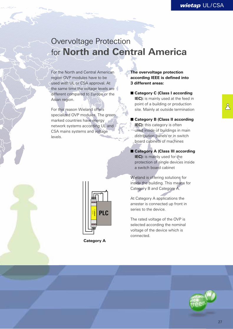
At Category A applications the
arrester is connected up front in
series to the device.
The rated voltage of the OVP is
selected according the nominal
voltage of the device which is
connected.
Category A
PLC
A Kw
A L Kw
wietap UL / CSA
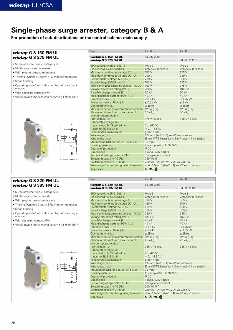
wietap G S 150 FM ULwietap G S 275 FM UL
wietap G S 320 FM ULwietap G S 385 FM UL
wietap G S 150 FM UL 84.995.2092.1wietap G S 275 FM UL 84.995.2090.1
wietap G S 320 FM UL 84.995.2093.1wietap G S 385 FM UL 84.995.2094.1
121114
121114
28
Single-phase surge arrester, category B & AFor protection of sub-distributions or the control cabinet main supply
Type Part No. Part No.
Type Part No. Part No.
• Surge arrester, type 2, category B
• Multi-purpose surge arrester
• With plug-in protection module
• Thermo Dynamic Control SPD monitoring device
• Small housing
• Operating state/fault indication by indicator flag in window
• With signaling contact (FM)
• Vibration and shock tested according EN 60068-2
SPD accord. to EN 61643-11 Type 2 Type 2 SPD accord. to IEC 61643-1 Category B / Class II Category B / Class II Maximum continuous voltage AC [UC] 150 V 275 V Maximum continuous voltage DC [UC] 200 V 350 V Rated varistor voltage AC [Umov] 200 V 350 V Rated voltage (50/60 Hz) [V] 150 V 275 V Max. continuous operating voltage [MCOV] 150 V 275 V Voltage protection rating [VPR] 700 V 1000 V Rated discharge current [In] 20 kA 20 kA Max. discharge current (8/20) [Imax] 40 kA 40 kA Protection level [UP] ≤ 0.7 kV ≤ 1.25 kV Protection level at 5 kA [UP] ≤ 0.55 kV ≤ 1 kV Operating time [tA] ≤ 25 ns ≤ 25 ns Maximum network overcurrent protection 125 A gL/gG 125 A gL/gG Short-circuit proof with max. network overcurrent protection
50 kArms 50 kArms
TOV-voltage [UT] 175 V / 5 sec. 335 V / 5 sec. Temperature range [TU] acc. to UL 1449 3rd edition acc. to EN 61643-11
0... +85 °C -40... +85 °C
Function/failure indication green / red Wire range (min.) 1.5 mm2 (AWG 14) solid/fi ne-strandedWire range (max.) 35 mm2 (AWG 2) stranded / 25 mm2 (AWG 4) fi ne-stranded
Mounted on DIN rail acc. to EN 60715 35 mm Housing material thermoplastic, UL 94 V-0 Degree of protection IP 20 Dimensions 1 mod., DIN 43880 Remote signaling contacts (FM) changeover contact Switching capacity AC (FM) 250 V/0.5 A Switching capacity DC (FM) 250 V/0.1 A; 125 V/0.2 A; 75 V/0.5 AWire range for remote signaling terminals max. 1.5 mm2 (AWG 14) solid/fi ne-stranded
Approvals
SPD accord. to EN 61643-11 Type 2 Type 2 SPD accord. to IEC 61643-1 Category B / Class II Category B / Class II Maximum continuous voltage AC [UC] 320 V 385 V Maximum continuous voltage DC [UC] 420 V 500 V Rated varistor voltage AC [Umov] 420 V 500 V Rated voltage (50/60 Hz) [V] 320 V 385 V Max. continuous operating voltage [MCOV] 320 V 385 V Voltage protection rating [VPR] 1200 V 1500 V Rated discharge current [In] 20 kA 20 kA Max. discharge current (8/20) [Imax] 40 kA 40 kA Protection level [UP] ≤ 1.5 kV ≤ 1.75 kV Protection level at 5 kA [UP] ≤ 1.2 kV ≤ 1.35 kV Operating time [tA] ≤ 25 ns ≤ 25 ns Maximum network overcurrent protection 125 A gL/gG 125 A gL/gG Short-circuit proof with max. network overcurrent protection
25 kArms 25 kArms
TOV-voltage [UT] 335 V / 5 sec. 385 V / 5 sec. Temperature range [TU] acc. to UL 1449 3rd edition acc. to EN 61643-11
0... +85 °C -40... +85 °C
Function/failure indication green / red Wire range (min.) 1.5 mm2 (AWG 14) solid/fi ne-strandedWire range (max.) 35 mm2 (AWG 2) stranded / 25 mm2 (AWG 4) fi ne-stranded
Mounted on DIN rail acc. to EN 60715 35 mm Housing material thermoplastic, UL 94 V-0 Degree of protection IP 20 Dimensions 1 mod., DIN 43880 Remote signaling contacts (FM) changeover contact Switching capacity AC (FM) 250 V/0.5 A Switching capacity DC (FM) 250 V/0.1 A; 125 V/0.2 A; 75 V/0.5 AWire range for remote signaling terminals max. 1.5 mm2 (AWG 14) solid/fi ne-stranded
Approvals
A Kw
A Kw
wietap UL / CSA
wietap G S 440 FM ULwietap G S 600 FM UL
wietap G S WE 600 FM UL
wietap G S 440 FM UL 84.995.2095.1wietap G S 600 FM UL 84.995.2096.1
wietap G S WE 600 FM UL 84.995.2097.1
121114
121114
29
Single-phase surge arrester, category B & AFor protection of sub-distributions or the control cabinet main supply
Type Part No. Part No.
Type Part No. Part No.
• Surge arrester, type 2, category B
• Multi-purpose surge arrester
• With plug-in protection module
• Thermo Dynamic Control SPD monitoring device
• Small housing
• Operating state/fault indication by indicator flag in window
• With signaling contact (FM)
• Vibration and shock tested according EN 60068-2
• Surge arrester, type 2, category B
• Multi-purpose surge arrester
• With plug-in protection module
• Thermo Dynamic Control SPD monitoring device
• Small housing
• Operating state/fault indication by indicator flag in window
• With signaling contact (FM)
• Vibration and shock tested according EN 60068-2
SPD accord. to EN 61643-11 Type 2 Type 2 SPD accord. to IEC 61643-1 Category B / Class II Category B / Class II Maximum continuous voltage AC [UC] 440 V 600 V Maximum continuous voltage DC [UC] 585 V 600 V Rated varistor voltage AC [Umov] 585 V 600 V Rated voltage (50/60 Hz) [V] 440 V 600 V Max. continuous operating voltage [MCOV] 440 V 600 V Voltage protection rating [VPR] 1500 V 2000 V Rated discharge current [In] 20 kA 20 kAMax. discharge current (8/20) [Imax] 40 kA 30 kA Protection level [UP] ≤ 2 kV ≤ 2.5 kV Protection level at 5 kA [UP] ≤ 1.7 kV ≤ 2 kV Operating time [tA] ≤ 25 ns ≤ 25 ns Maximum network overcurrent protection 125 A gL/gG 100 A gL/gG Short-circuit proof with max. network overcurrent protection
25 kArms 25 kArms
TOV-voltage [UT] 580 V / 5 sec. 600 V / 5 sec. Temperature range [TU] acc. to UL 1449 3rd edition acc. to EN 61643-11
0... +85 °C -40... +85 °C
Function/failure indication green / red Wire range (min.) 1.5 mm2 (AWG 14) solid/fi ne-strandedWire range (max.) 35 mm2 (AWG 2) stranded / 25 mm2 (AWG 4) fi ne-stranded
Mounted on DIN rail acc. to EN 60715 35 mm Housing material thermoplastic, UL 94 V-0 Degree of protection IP 20 Dimensions 1 mod., DIN 43880 Remote signaling contacts (FM) changeover contact Switching capacity AC (FM) 250 V/0.5 A Switching capacity DC (FM) 250 V/0.1 A; 125 V/0.2 A; 75 V/0.5 AWire range for remote signaling terminals max. 1.5 mm2 (AWG 14) solid/fi ne-stranded
Approvals
SPD accord. to EN 61643-11 Type 2 SPD accord. to IEC 61643-1 Category B / Class II Maximum continuous voltage AC [UC] 600 V Maximum continuous voltage DC [UC] 600 V Rated varistor voltage AC [Umov] 750VRated voltage (50/60 Hz) [V] 600 V Max. continuous operating voltage [MCOV] 750 V Voltage protection rating [VPR] 2500VRated discharge current [In] 10 kAMax. discharge current (8/20) [Imax] 25 kA Protection level [UP] ≤ 3 kV Protection level at 5 kA [UP] ≤ 2.5 kV Operating time [tA] ≤ 25 ns Maximum network overcurrent protection 100 A gL/gG Short-circuit proof with max. network overcurrent protection
25 kArms
TOV-voltage [UT] 900 V / 5 sec. Temperature range [TU] acc. to UL 1449 3rd edition acc. to EN 61643-11
0... +85 °C -40... +85 °C
Function/failure indication green / red Wire range (min.) 1.5 mm2 (AWG 14) solid/fi ne-strandedWire range (max.) 35 mm2 (AWG 2) stranded / 25 mm2 (AWG 4) fi ne-stranded
Mounted on DIN rail acc. to EN 60715 35 mm Housing material thermoplastic, UL 94 V-0 Degree of protection IP 20 Dimensions 1 mod., DIN 43880 Remote signaling contacts (FM) changeover contact Switching capacity AC (FM) 250 V/0.5 A Switching capacity DC (FM) 250 V/0.1 A; 125 V/0.2 A; 75 V/0.5 AWire range for remote signaling terminals max. 1.5 mm2 (AWG 14) solid/fi ne-stranded
Approvals

wietap R M 2P 30 FM
wietap R M 2P 150 FM
A Kw
A Kw
wietap UL / CSA
wietap R M 2P 30 FM 84.995.3206.0
wietap R M 2P 150 FM 84.995.3209.0
1 3
2 4
12
11
14
1 3
2 4
12
11
14
30
Surge arrester, category AFor direct load protection in control cabinets or sub-distributions
• Surge arrester, type 3
• Two-pole surge arrester
• High discharge capacity due to powerful zinc oxide varistor
• Slim design (modular construction) acc. to DIN 43880
• With pluggable protection modules
• Function/failure indication according to VDE 0100-534
• With remote signaling contact (FM)
• Vibration and shock tested acc. to EN 60068-2
Type Part No.
Type Part No.
Technical Data SPD accord. to EN 61643-11 Type 3 SPD accord. to IEC 61643-1 Category A / Class III Rated voltage (50/60 Hz) [V] 24 VMaximum continuous voltage AC [UC] 30 V Maximum continuous voltage DC [UC] 30 V Max. continuous operating voltage [MCOV] 30 V Voltage protection rating [VPR] 330 V Rated current AC acc. UL 1449 3rd edition | EN 61643-11 20 A | 25 ARated discharge current (8/20) [In] 1 kA Total discharge current (8/20) [L+N-PE] [Itotal] 2 kA Combined surge [UOC] 2 kV Combined surge [L+N-PE] [UOC total] 4 kV Protection level [L-N] [UP] ≤ 180 V Protection level [L/N-PE] [UP] ≤ 630 V Operating time [L-N] [tA] ≤ 25 ns Operating time [L/N-PE] [tA] ≤ 100 ns Maximum network overcurrent protection 25 A gL/gG or B 25 A
Short-circuit proof with network overcurrentprotection with 25 A gL/gG
6 kArms
Temperature range [TU] acc. to UL 1449 3rd edition acc. to EN 61643-11
0... +85 °C -40... +85 °C
Function/failure indication green / red Wire range (min.) 0.5 mm² (AWG 20) solid/fi ne-strandedWire range (max.) 4 mm² (AWG 12) solid / 2.5 mm² (AWG 14) fi ne-stranded
Mounted on DIN rail acc. to EN 60715 35 mmHousing material thermoplastic, UL 94 V-0 Degree of protection IP 20 Dimensions 1 mod., DIN 43880 Remote signaling contacts (FM) changeover contact Switching capacity AC (FM) 250 V/0.5 A Switching capacity DC (FM) 250 V/0.1 A; 125 V/0.2 A; 75 V/0.5 A Wire range for remote signaling terminals max. 1.5 mm2 (AWG 16) solid/fine-stranded
Approvals
Technical Data SPD accord. to EN 61643-11 Type 3 SPD accord. to IEC 61643-1 Category A / Class III Rated voltage (50/60 Hz) 120 VMaximum continuous voltage AC [UC] 150 V Maximum continuous voltage DC [UC] 150 V Max. continuous operating voltage [MCOV] 150 V Voltage protection rating [VPR] 700 V Rated current AC acc. UL 1449 3rd edition | EN 61643-11 20 A | 25 ARated discharge current (8/20) [In] 2 kA Total discharge current (8/20) [L+N-PE] [Itotal] 4 kA Combined surge [UOC] 4 kV Combined surge [L+N-PE] [UOC total] 8 kV Protection level [L-N] [UP] ≤ 640 V Protection level [L/N-PE] [UP] ≤ 800 V Operating time [L-N] [tA] ≤ 25 ns Operating time [L/N-PE] [tA] ≤ 100 ns Maximum network overcurrent protection 25 A gL/gG or B 25 A
Short-circuit proof with network overcurrentprotection with 25 A gL/gG
6 kArms
Temperature range [TU] acc. to UL 1449 3rd edition acc. to EN 61643-11
0... +85 °C -40... +85 °C
Function/failure indication green / red Wire range (min.) 0.5 mm² (AWG 20) solid/fi ne-strandedWire range (max.) 4 mm² (AWG 12) solid / 2.5 mm² (AWG 14) fi ne-stranded
Mounted on DIN rail acc. to EN 60715 35 mmHousing material thermoplastic, UL 94 V-0 Degree of protection IP 20 Dimensions 1 mod., DIN 43880 Remote signaling contacts (FM) changeover contact Switching capacity AC (FM) 250 V/0.5 A Switching capacity DC (FM) 250 V/0.1 A; 125 V/0.2 A; 75 V/0.5 AWire range for remote signaling terminals max. 1.5 mm2 (AWG 14) solid/fine-stranded
Approvals
AöKw
AöKw
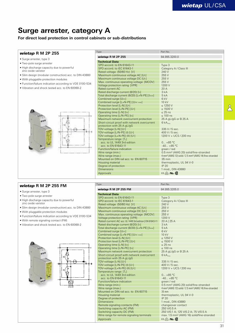
wietap R M 2P 255
wietap R M 2P 255 FM
wietap UL / CSA
wietap R M 2P 255 84.995.3200.0
wietap R M 2P 255 FM 84.995.3205.0
31
Type Part No.
Type Part No.
Technical Data SPD accord. to EN 61643-11 Type 3 SPD accord. to IEC 61643-1 Category A / Class III Rated voltage (50/60 Hz) [V] 240 VMaximum continuous voltage AC [UC] 255 V Maximum continuous voltage DC [UC] 255 V Max. continuous operating voltage [MCOV] 255 V Voltage protection rating [VPR] 1200 V Rated current AC 20 ARated discharge current (8/20) [In] 3 kA Total discharge current (8/20) [L+N-PE] [Itotal] 5 kA Combined surge [UOC] 6 kV Combined surge [L+N-PE] [UOC total] 10 kV Protection level [L-N] [UP] ≤ 1250 V Protection level [L/N-PE] [UP] ≤ 1500 V Operating time [L-N] [tA] ≤ 25 ns Operating time [L/N-PE] [tA] ≤ 100 ns Maximum network overcurrent protection 25 A gL/gG or B 25 A
Short-circuit proof with network overcurrentprotection with 25 A gL/gG
6 kArms
TOV-voltage [L-N] [UT] 335 V / 5 sec. TOV-voltage [L/N-PE] (I) [UT] 400 V / 5 sec. TOV-voltage [L+N-PE] (II) [UT] 1200 V + UCS / 200 ms Temperature range [TU] acc. to UL 1449 3rd edition acc. to EN 61643-11
0... +85 °C -40... +85 °C
Function/failure indication green / red Wire range (min.) 0.5 mm² (AWG 20) solid/fi ne-stranded Wire range (max.) 4 mm² (AWG 12) solid / 2.5 mm² (AWG 14) fi ne-stranded
Mounted on DIN rail acc. to EN 60715 35 mmHousing material thermoplastic, UL 94 V-0 Degree of protection IP 20 Dimensions 1 mod., DIN 43880
Approvals
Technical Data SPD accord. to EN 61643-11 Type 3 SPD accord. to IEC 61643-1 Category A / Class III Rated voltage (50/60 Hz) [V] 240 VMaximum continuous voltage AC [UC] 255 V Maximum continuous voltage DC [UC] 255 V Max. continuous operating voltage [MCOV] 255 V Voltage protection rating [VPR] 1200 V Rated current AC acc. UL 1449 3rd edition | EN 61643-11 20 A | 25 ARated discharge current (8/20) [In] 3 kA Total discharge current (8/20) [L+N-PE] [Itotal] 5 kA Combined surge [UOC] 6 kV Combined surge [L+N-PE] [UOC total] 10 kV Protection level [L-N] [UP] ≤ 1250 V Protection level [L/N-PE] [UP] ≤ 1500 V Operating time [L-N] [tA] ≤ 25 ns Operating time [L/N-PE] [tA] ≤ 100 ns Maximum network overcurrent protection 25 A gL/gG or B 25 A
Short-circuit proof with network overcurrentprotection with 25 A gL/gG
6 kArms
TOV-voltage [L-N] [UT] 335 V / 5 sec. TOV-voltage [L/N-PE] (I) [UT] 400 V / 5 sec. TOV-voltage [L+N-PE] (II) [UT] 1200 V + UCS / 200 ms Temperature range [TU] acc. to UL 1449 3rd edition acc. to EN 61643-11
0... +85 °C -40... +85 °C
Function/failure indication green / red Wire range (min.) 0.5 mm² (AWG 20) solid/fi ne-stranded Wire range (max.) 4 mm² (AWG 12) solid / 2.5 mm² (AWG 14) fi ne-stranded
Mounted on DIN rail acc. to EN 60715 35 mm
Housing material thermoplastic, UL 94 V-0 Degree of protection IP 20 Dimensions 1 mod., DIN 43880 Remote signaling contacts (FM) changeover contact Switching capacity AC (FM) 250 V/0.5 A Switching capacity DC (FM) 250 V/0.1 A; 125 V/0.2 A; 75 V/0.5 AWire range for remote signaling terminals max. 1.5 mm2 (AWG 16) solid/fine-stranded
Approvals
Surge arrester, category AFor direct load protection in control cabinets or sub-distributions
• Surge arrester, type 3
• Two-pole surge arrester
• High discharge capacity due to powerful zinc oxide varistor
• Slim design (modular construction) acc. to DIN 43880
• With pluggable protection modules
• Function/failure indication according to VDE 0100-534
• Vibration and shock tested acc. to EN 60068-2
• Surge arrester, type 3
• Two-pole surge arrester
• High discharge capacity due to powerful zinc oxide varistor
• Slim design (modular construction) acc. to DIN 43880
• With pluggable protection modules
• Function/failure indication according to VDE 0100-534
• With remote signaling contact (FM)
• Vibration and shock tested acc. to EN 60068-2

32
33
wietap DC Solar
DC
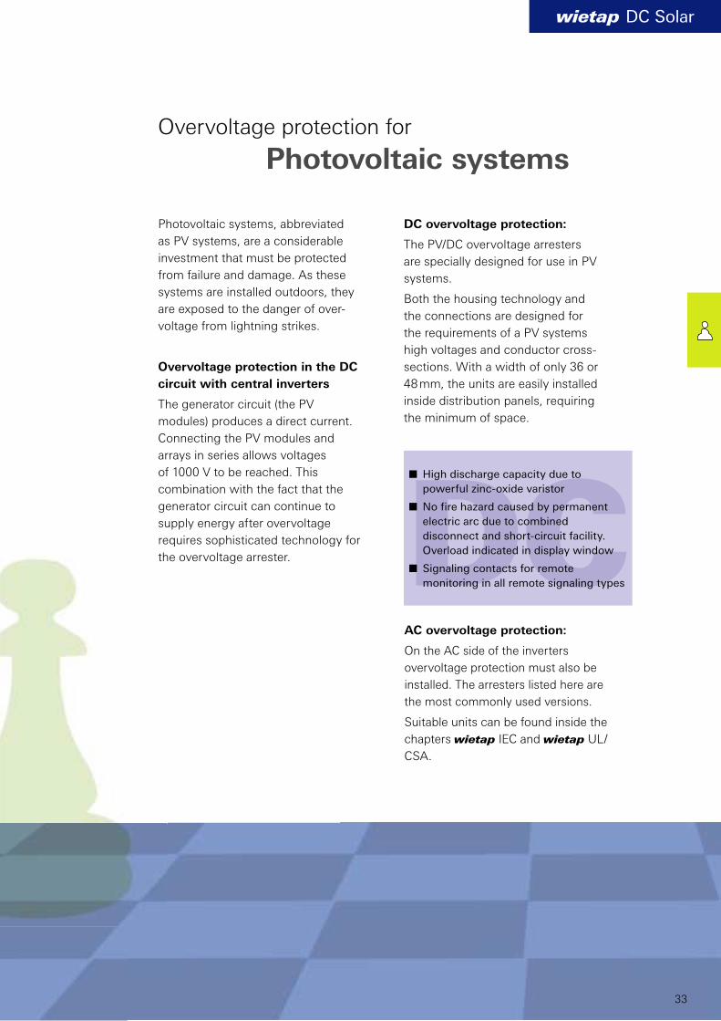
Photovoltaic systems, abbreviated
as PV systems, are a considerable
investment that must be protected
from failure and damage. As these
systems are installed outdoors, they
are exposed to the danger of over-
voltage from lightning strikes.
Overvoltage protection in the DC
circuit with central inverters
The generator circuit (the PV
modules) produces a direct current.
Connecting the PV modules and
arrays in series allows voltages
of 1000 V to be reached. This
combination with the fact that the
generator circuit can continue to
supply energy after overvoltage
requires sophisticated technology for
the overvoltage arrester.
Overvoltage protection for
Photovoltaic systems
DC overvoltage protection:
The PV/DC overvoltage arresters
are specially designed for use in PV
systems.
Both the housing technology and
the connections are designed for
the requirements of a PV systems
high voltages and conductor cross-
sections. With a width of only 36 or
48 mm, the units are easily installed
inside distribution panels, requiring
the minimum of space.
n High discharge capacity due to
powerful zinc-oxide varistor
n No fire hazard caused by permanent
electric arc due to combined
disconnect and short-circuit facility.
Overload indicated in display window
n Signaling contacts for remote
monitoring in all remote signaling types
AC overvoltage protection:
On the AC side of the inverters
overvoltage protection must also be
installed. The arresters listed here are
the most commonly used versions.
Suitable units can be found inside the
chapters wietap IEC and wietap UL/
CSA.
A Kw
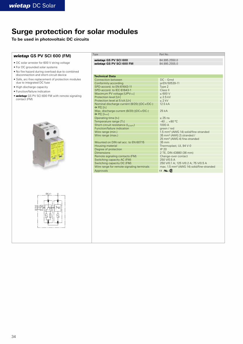
wietap GS PV SCI 600 (FM)
wietap DC Solar
wietap GS PV SCI 600 84.995.2550.0wietap GS PV SCI 600 FM 84.995.2555.0
34
Surge protection for solar modulesTo be used in photovoltaic DC circuits
• DC solar arrester for 600 V string voltage
• For DC grounded solar systems
• No fire hazard during overload due to combineddisconnection and short-circuit device
• Safe, arc-free replacement of protection modules due to integrated DC fuse
• High discharge capacity
• Function/failure indication
• wietap GS PV SCI 600 FM with remote signaling contact (FM)
Type Part No.
Technical Data Connection between DC – GrndConformity according prEN 50539-11SPD-accord. to EN 61643-11 Type 2 SPD-accord. to IEC 61643-1 Class II Maximum PV voltage [UPVmax] ≤ 600 V Protection level [UP] ≤ 2.5 kV Protection level at 5 kA [UP] ≤ 2 kV Nominal discharge current (8/20) [(DC+/DC-) à PE] [In]
12.5 kA
Max. discharge current (8/20) [(DC+/DC-) à PE] [Imax]
25 kA
Operating time [tA] ≤ 25 ns Temperature range [TU] -40 ... +80 °C Short-circuit resistance (ISCWPV) 1000 A Function/failure indication green / red Wire range (min.) 1.5 mm² (AWG 14) solid/fi ne-strandedWire range (max.) 35 mm² (AWG 2) stranded /
25 mm² (AWG 4) fi ne-strandedMounted on DIN rail acc. to EN 60715 35 mmHousing material Thermoplast, UL 94 V-0Degree of protection IP 20 Dimensions 2 TE, DIN 43880 (36 mm) Remote signaling contacts (FM) Change-over contact Switching capacity AC (FM) 250 V/0.5 A Switching capacity DC (FM) 250 V/0.1 A; 125 V/0.2 A; 75 V/0.5 AWire range for remote signaling terminals max. 1.5 mm² (AWG 14) solid/fi ne-stranded
Approvals
A Kw
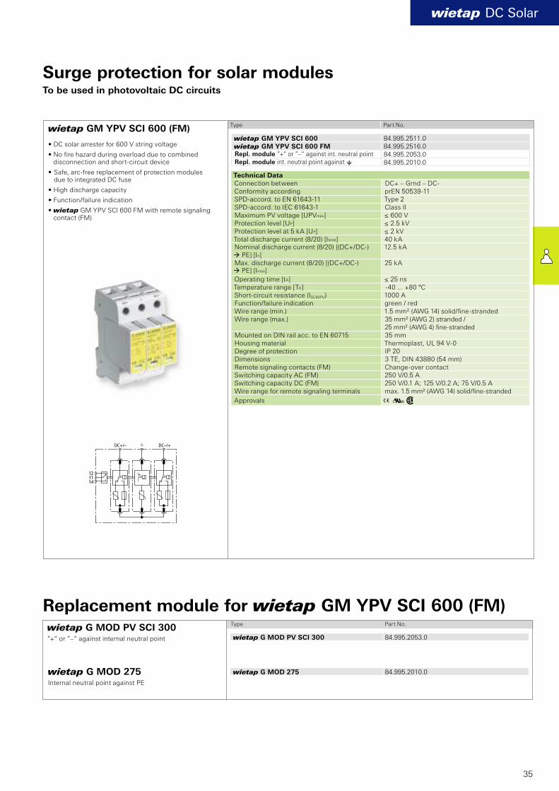
wietap GM YPV SCI 600 (FM)
wietap DC Solar
wietap G MOD PV SCI 300 84.995.2053.0
wietap G MOD 275 84.995.2010.0
wietap GM YPV SCI 600 84.995.2511.0wietap GM YPV SCI 600 FM 84.995.2516.0
84.995.2053.084.995.2010.0
35
Surge protection for solar modulesTo be used in photovoltaic DC circuits
Type Part No.
Technical Data Connection between DC+ – Grnd – DC-Conformity according prEN 50539-11SPD-accord. to EN 61643-11 Type 2 SPD-accord. to IEC 61643-1 Class II Maximum PV voltage [UPVmax] ≤ 600 V Protection level [UP] ≤ 2.5 kV Protection level at 5 kA [UP] ≤ 2 kV Total discharge current (8/20) [Itotal] 40 kA Nominal discharge current (8/20) [(DC+/DC-) à PE] [In]
12.5 kA
Max. discharge current (8/20) [(DC+/DC-) à PE] [Imax]
25 kA
Operating time [tA] ≤ 25 ns Temperature range [TU] -40 ... +80 °C Short-circuit resistance (ISCWPV) 1000 A Function/failure indication green / red Wire range (min.) 1.5 mm² (AWG 14) solid/fi ne-strandedWire range (max.) 35 mm² (AWG 2) stranded /
25 mm² (AWG 4) fi ne-strandedMounted on DIN rail acc. to EN 60715 35 mmHousing material Thermoplast, UL 94 V-0Degree of protection IP 20 Dimensions 3 TE, DIN 43880 (54 mm) Remote signaling contacts (FM) Change-over contact Switching capacity AC (FM) 250 V/0.5 A Switching capacity DC (FM) 250 V/0.1 A; 125 V/0.2 A; 75 V/0.5 AWire range for remote signaling terminals max. 1.5 mm² (AWG 14) solid/fi ne-stranded
Approvals
Type Part No.
wietap G MOD 275Internal neutral point against PE
Replacement module for wietap GM YPV SCI 600 (FM)
Repl. module ”+“ or ”–“ against int. neutral pointRepl. module int. neutral point against e
wietap G MOD PV SCI 300”+“ or ”–“ against internal neutral point
• DC solar arrester for 600 V string voltage
• No fire hazard during overload due to combineddisconnection and short-circuit device
• Safe, arc-free replacement of protection modules due to integrated DC fuse
• High discharge capacity
• Function/failure indication
• wietap GM YPV SCI 600 FM with remote signaling contact (FM)

A Kw
wietap GM YPV SCI 1000 (FM)
wietap DC Solar
wietap G MOD PV SCI 500 84.995.2051.0
wietap G MOD 440 84.995.2015.0
wietap GM YPV SCI 1000 84.995.2510.0wietap GM YPV SCI 1000 FM 84.995.2515.0
84.995.2051.084.995.2015.0
36
Surge protection for solar modulesTo be used in photovoltaic DC circuits
• DC solar arrester for 1000 V string voltage
• No fire hazard during overload due to combineddisconnection and short-circuit device
• Safe, arc-free replacement of protection modules due to integrated DC fuse
• High discharge capacity
• Function/failure indication
• wietap GM YPV SCI 1000 FM with remote signaling contact (FM)
Type Part No.
Technical Data Connection between DC+ – Grnd – DC-Conformity according prEN 50539-11SPD-accord. to EN 61643-11 Type 2 SPD-accord. to IEC 61643-1 Class II Maximum PV voltage [UPVmax] ≤ 1000 V Protection level [UP] ≤ 4 kV Protection level at 5 kA [UP] ≤ 3.5 kV Total discharge current (8/20) [Itotal] 40 kA Nominal discharge current (8/20) [(DC+/DC-) à PE] [In]
12.5 kA
Max. discharge current (8/20) [(DC+/DC-) à PE] [Imax]
25 kA
Operating time [tA] ≤ 25 ns Temperature range [TU] -40 ... +80 °C Short-circuit resistance (ISCWPV) 1000 A Function/failure indication green / red Wire range (min.) 1.5 mm² (AWG 14) solid/fi ne-stranded Wire range (max.) 35 mm² (AWG 2) stranded /
25 mm² (AWG 4) fi ne-stranded Mounted on DIN rail acc. to EN 60715 35 mmHousing material Thermoplast, UL 94 V-0Degree of protection IP 20 Dimensions 3 TE, DIN 43880 (54 mm) Remote signaling contacts (FM) Change-over contact Switching capacity AC (FM) 250 V/0.5 A Switching capacity DC (FM) 250 V/0.1 A; 125 V/0.2 A; 75 V/0.5 AWire range for remote signaling terminals max. 1.5 mm² (AWG 14) solid/fi ne-stranded
Approvals
Type Part No.
wietap G MOD 440Internal neutral point against PE
Replacement module for wietap GM YPV SCI 1000 (FM)
Repl. module ”+“ or ”–“ against int. neutral pointRepl. module int. neutral point against e
wietap G MOD PV SCI 500”+“ or ”–“ against internal neutral point
wietap DC Solar
DDDDCCCCCCCCCCCCDDDDDDDDDDDCCCCCCCCCCCCCCCCCDDDDDDDDCCCCCCCCCDDDDDDDDDDDDCCCCCCCCCCCCDDDDDDDDDDDDDDDDDDDDDDDDDDDDDCCCCCCCCCCCCCCCCCCCCCCCCCCCCCCCCCCCCCCCCCCCCCCCCCCCCCCCCCCCCCCCCCCCCCCCCCCCCCCCCCCCCCCCC
gesis
®S
OL
AR
gesis® SOLARElektrische Installations- technik für PhotovoltaikKatalog
– Softwarelösungen mit Schnittstellen zu CAE-Systemen
– erhöhte Umweltbedingungen mit Bahn- u. Schiffszulassung
37
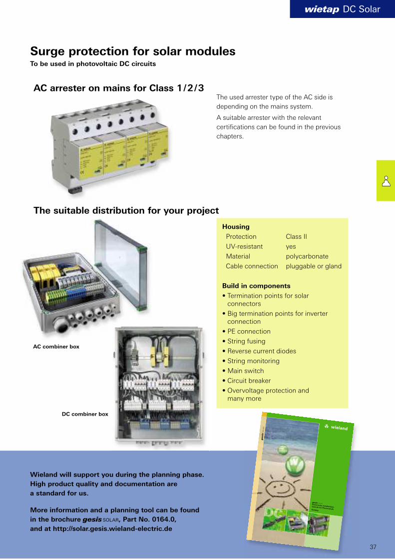
Surge protection for solar modulesTo be used in photovoltaic DC circuits
AC arrester on mains for Class 1 / 2 / 3
The suitable distribution for your project
The used arrester type of the AC side is
depending on the mains system.
A suitable arrester with the relevant
certifi cations can be found in the previous
chapters.
AC combiner box
DC combiner box
Wieland will support you during the planning phase.
High product quality and documentation are
a standard for us.
More information and a planning tool can be found
in the brochure gesis SOLAR, Part No. 0164.0,
and at http://solar.gesis.wieland-electric.de
Housing
Protection Class II
UV-resistant yes
Material polycarbonate
Cable connection pluggable or gland
Build in components
• Termination points for solar connectors
• Big termination points for inverter connection
• PE connection
• String fusing
• Reverse current diodes
• String monitoring
• Main switch
• Circuit breaker
• Overvoltage protection and many more
38
wipos
39
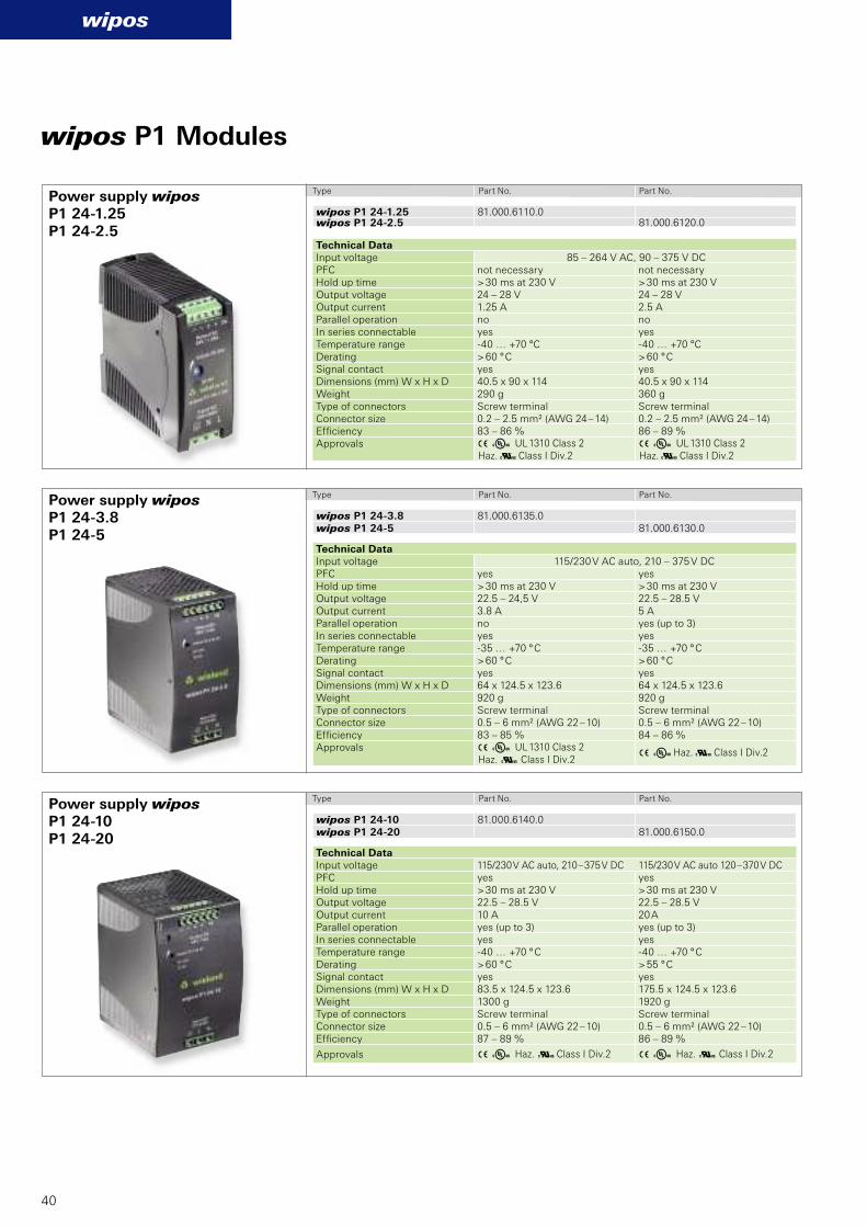
Power supplies perform a central
function in the control cabinet.
Their reliability affects the avail-
ability of the machine or the pro-
cess to a great degree. That is why
a robust and proven design is very
important for a power supply unit.
There are no unnecessary frills with
the wipos family. Instead, these
power supply units score with their
fundamental features.
wipos satisfies your
requirements in the significant
disciplines:
wipos Power supply units Pure Power. No-Frills.
100 % power up to 60° C
Automatic or wide-input voltage
range for worldwide use
PFC-technology
for high functional reliability
Outdoor installation possible
due to wide temperature range
Active monitoring
with signalling contact
Can be connected in parallel (from
5 A) to increase power and redundancy
High operational reliability
due to long hold-up times >30 ms
Compensation of voltage drops
via adjustable output voltage
Easy to commission
via LED diagnosis
For mounting
on DIN Rail TS 35 / TS 32
3 Y UL 1310 Class 2Haz. a Class I Div.2
3 Y UL 1310 Class 2Haz. a Class I Div.2
3 Y UL 1310 Class 2Haz. a Class I Div.2
3 Y Haz. a Class I Div.2
3 Y Haz. a Class I Div.2 3 Y Haz. a Class I Div.2
wipos P1 24-1.25 81.000.6110.0wipos P1 24-2.5 81.000.6120.0
wipos P1 24-3.8 81.000.6135.0wipos P1 24-5 81.000.6130.0
wipos P1 24-10 81.000.6140.0wipos P1 24-20 81.000.6150.0
P1 24-1.25P1 24-2.5
P1 24-10P1 24-20
P1 24-3.8P1 24-5
wipos
40
Power supply wipos
Power supply wipos
Power supply wipos
wipos P1 Modules
Type Part No. Part No.
Type Part No. Part No.
Technical Data Input voltage 85 – 264 V AC, 90 – 375 V DCPFC not necessary not necessaryHold up time > 30 ms at 230 V > 30 ms at 230 VOutput voltage 24 – 28 V 24 – 28 VOutput current 1.25 A 2.5 AParallel operation no noIn series connectable yes yesTemperature range -40 … +70 °C -40 … +70 °CDerating > 60 ° C > 60 ° CSignal contact yes yesDimensions (mm) W x H x D 40.5 x 90 x 114 40.5 x 90 x 114Weight 290 g 360 gType of connectors Screw terminal Screw terminalConnector size 0.2 – 2.5 mm² (AWG 24 – 14) 0.2 – 2.5 mm² (AWG 24 – 14)Effi ciency 83 – 86 % 86 – 89 %Approvals
Technical Data Input voltage 115/230 V AC auto, 210 – 375 V DCPFC yes yesHold up time > 30 ms at 230 V > 30 ms at 230 VOutput voltage 22.5 – 24,5 V 22.5 – 28.5 VOutput current 3.8 A 5 AParallel operation no yes (up to 3)In series connectable yes yesTemperature range -35 … +70 ° C -35 … +70 ° CDerating > 60 ° C > 60 ° CSignal contact yes yesDimensions (mm) W x H x D 64 x 124.5 x 123.6 64 x 124.5 x 123.6Weight 920 g 920 gType of connectors Screw terminal Screw terminalConnector size 0.5 – 6 mm² (AWG 22 – 10) 0.5 – 6 mm² (AWG 22 – 10)Effi ciency 83 – 85 % 84 – 86 %Approvals
Type Part No. Part No.
Technical Data Input voltage 115/230 V AC auto, 210 – 375 V DC 115/230 V AC auto 120 – 370 V DCPFC yes yesHold up time > 30 ms at 230 V > 30 ms at 230 VOutput voltage 22.5 – 28.5 V 22.5 – 28.5 VOutput current 10 A 20 AParallel operation yes (up to 3) yes (up to 3)In series connectable yes yesTemperature range -40 … +70 ° C -40 … +70 ° CDerating > 60 ° C > 55 ° CSignal contact yes yesDimensions (mm) W x H x D 83.5 x 124.5 x 123.6 175.5 x 124.5 x 123.6Weight 1300 g 1920 gType of connectors Screw terminal Screw terminalConnector size 0.5 – 6 mm² (AWG 22 – 10) 0.5 – 6 mm² (AWG 22 – 10)Effi ciency 87 – 89 % 86 – 89 %
Approvals
3 Y Haz. a Class I Div.2
3 Y Haz. a Class I Div.2
3 Y Haz. a Class I Div.2
wipos P1 12-5 81.000.6132.0
wipos P1 12-10 81.000.6142.0
wipos P1 48-5 81.000.6134.0
P1 12-5
P1 48-5
P1 12-10
wipos
41
Power supply wipos
Power supply wipos
Power supply wipos
wipos P1 Modules
Type Part No.
Type Part No.
Technical Data Input voltage 85 – 264 V AC, 90 – 375 V DC PFC not necessary Hold up time > 30 ms at 230 V Output voltage 12 – 14 VOutput current 5 AParallel operation no In series connectable yes Temperature range -40 … +70 °C Derating >61 °CSignal contact no Dimensions (mm) W x H x D 40.5 x 90 x 114Weight 340 g Type of connectors Screw terminal Connector size 0.2 – 2.5 mm² (AWG 24 – 14)Effi ciency 86 %
Approvals
Technical Data Input voltage 115/230 V AC auto, 210 – 375 V DCPFC not necessary Hold up time > 30 ms at 230 V Output voltage 11,4 – 14,5 VOutput current 10 AParallel operation yes (up to 3)In series connectable yes Temperature range -35 … +70 °C Derating >61 °CSignal contact no Dimensions (mm) W x H x D 64 x 124.5 x 123.6Weight 920 g Type of connectors Screw terminal Connector size 0.5 – 6 mm² (AWG 22 – 10)Effi ciency 84 %
Approvals
Type Part No.
Technical Data Input voltage 115/230 V AC auto, 210 – 375 V DCPFC not necessary Hold up time >30 ms at 230 V Output voltage 47 – 56 VOutput current 5 AParallel operation yes (up to 3)In series connectable yes Temperature range -40 … +70 °C Derating >61 °CSignal contact no Dimensions (mm) W x H x D 83.5 x 124.5 x 123.6Weight 1380 gType of connectors Screw terminal Connector size 0.5 – 6 mm2 solid/fi ne str. (AWG 22 – 10)Effi ciency 90 %
Approvals
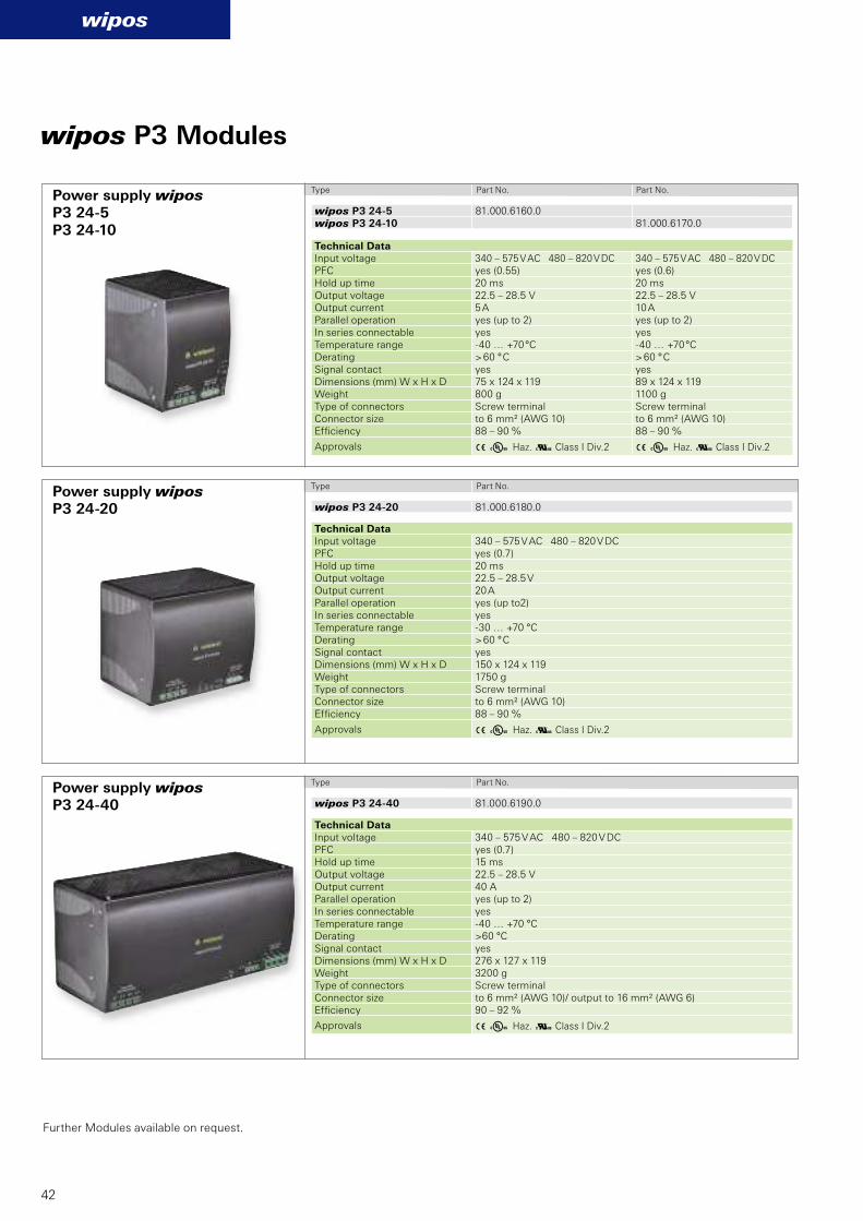
P3 24-5 P3 24-10
P3 24-40
P3 24-20
3 Y Haz. a Class I Div.2 3 Y Haz. a Class I Div.2
3 Y Haz. a Class I Div.2
3 Y Haz. a Class I Div.2
wipos P3 24-5 81.000.6160.0wipos P3 24-10 81.000.6170.0
wipos P3 24-20 81.000.6180.0
wipos P3 24-40 81.000.6190.0
wipos
42
wipos P3 Modules
Power supply wipos
Power supply wipos
Power supply wipos
Type Part No. Part No.
Type Part No.
Technical Data Input voltage 340 – 575 V AC 480 – 820 V DC 340 – 575 V AC 480 – 820 V DCPFC yes (0.55) yes (0.6)Hold up time 20 ms 20 msOutput voltage 22.5 – 28.5 V 22.5 – 28.5 VOutput current 5 A 10 AParallel operation yes (up to 2) yes (up to 2)In series connectable yes yesTemperature range -40 … +70 °C -40 … +70 °CDerating > 60 ° C > 60 ° CSignal contact yes yesDimensions (mm) W x H x D 75 x 124 x 119 89 x 124 x 119Weight 800 g 1100 gType of connectors Screw terminal Screw terminalConnector size to 6 mm² (AWG 10) to 6 mm² (AWG 10)Effi ciency 88 – 90 % 88 – 90 %
Approvals
Technical Data Input voltage 340 – 575 V AC 480 – 820 V DCPFC yes (0.7)Hold up time 20 msOutput voltage 22.5 – 28.5 VOutput current 20 AParallel operation yes (up to2)In series connectable yesTemperature range -30 … +70 °CDerating > 60 ° CSignal contact yesDimensions (mm) W x H x D 150 x 124 x 119Weight 1750 gType of connectors Screw terminalConnector size to 6 mm² (AWG 10)Effi ciency 88 – 90 %
Approvals
Type Part No.
Technical Data Input voltage 340 – 575 V AC 480 – 820 V DCPFC yes (0.7)Hold up time 15 msOutput voltage 22.5 – 28.5 VOutput current 40 AParallel operation yes (up to 2)In series connectable yesTemperature range -40 … +70 °CDerating >60 °CSignal contact yesDimensions (mm) W x H x D 276 x 127 x 119Weight 3200 gType of connectors Screw terminalConnector size to 6 mm² (AWG 10)/ output to 16 mm² (AWG 6)Effi ciency 90 – 92 %
Approvals
Further Modules available on request.
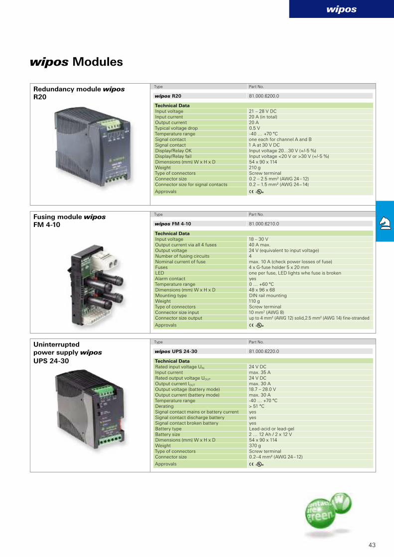
3 Y
wipos R20 81.000.6200.0
R20
3 Y
3 Y
wipos FM 4-10 81.000.6210.0
wipos UPS 24-30 81.000.6220.0
FM 4-10
UPS 24-30
wipos
43
Technical Data Input voltage 21 – 28 V DCInput current 20 A (in total)Output current 20 ATypical voltage drop 0.5 VTemperature range -40 … +70 °C Signal contact one each for channel A and BSignal contact 1 A at 30 V DCDisplay/Relay OK Input voltage 20…30 V (+/-5 %)Display/Relay fail Input voltage <20 V or >30 V (+/-5 %)Dimensions (mm) W x H x D 54 x 90 x 114Weight 210 gType of connectors Screw terminal Connector size 0.2 – 2.5 mm² (AWG 24 – 12)Connector size for signal contacts 0.2 – 1.5 mm² (AWG 24 – 14)
Approvals
Technical Data Input voltage 18 – 30 VOutput current via all 4 fuses 40 A max.Output voltage 24 V (equivalent to input voltage)Number of fusing circuits 4Nominal current of fuse max. 10 A (check power losses of fuse)Fuses 4 x G-fuse holder 5 x 20 mmLED one per fuse, LED lights whe fuse is brokenAlarm contact yesTemperature range 0 … +60 °CDimensions (mm) W x H x D 48 x 96 x 68 Mounting type DIN rail mountingWeight 110 gType of connectors Screw terminal Connector size input 10 mm2 (AWG 8)Connector size output up to 4 mm2 (AWG 12) solid,2.5 mm2 (AWG 14) fi ne-stranded
Approvals
Technical Data Rated input voltage UIN 24 V DCInput current max. 35 ARated output voltage UOUT 24 V DCOutput current IOUT max. 30 AOutput voltage (battery mode) 18.7 – 28.0 VOutput current (battery mode) max. 30 ATemperature range -40 … +70 °CDerating > 51 °CSignal contact mains or battery current yes Signal contact discharge battery yes Signal contact broken battery yes Battery type Lead-acid or lead-gel Battery size 2 … 12 Ah / 2 x 12 V Dimensions (mm) W x H x D 54 x 90 x 114Weight 370 gType of connectors Screw terminal Connector size 0.2–4 mm² (AWG 24 – 12)
Approvals
wipos Modules
Redundancy module wipos Type Part No.
Type Part No.
Type Part No.
Fusing module wipos
Uninterrupted power supply wipos
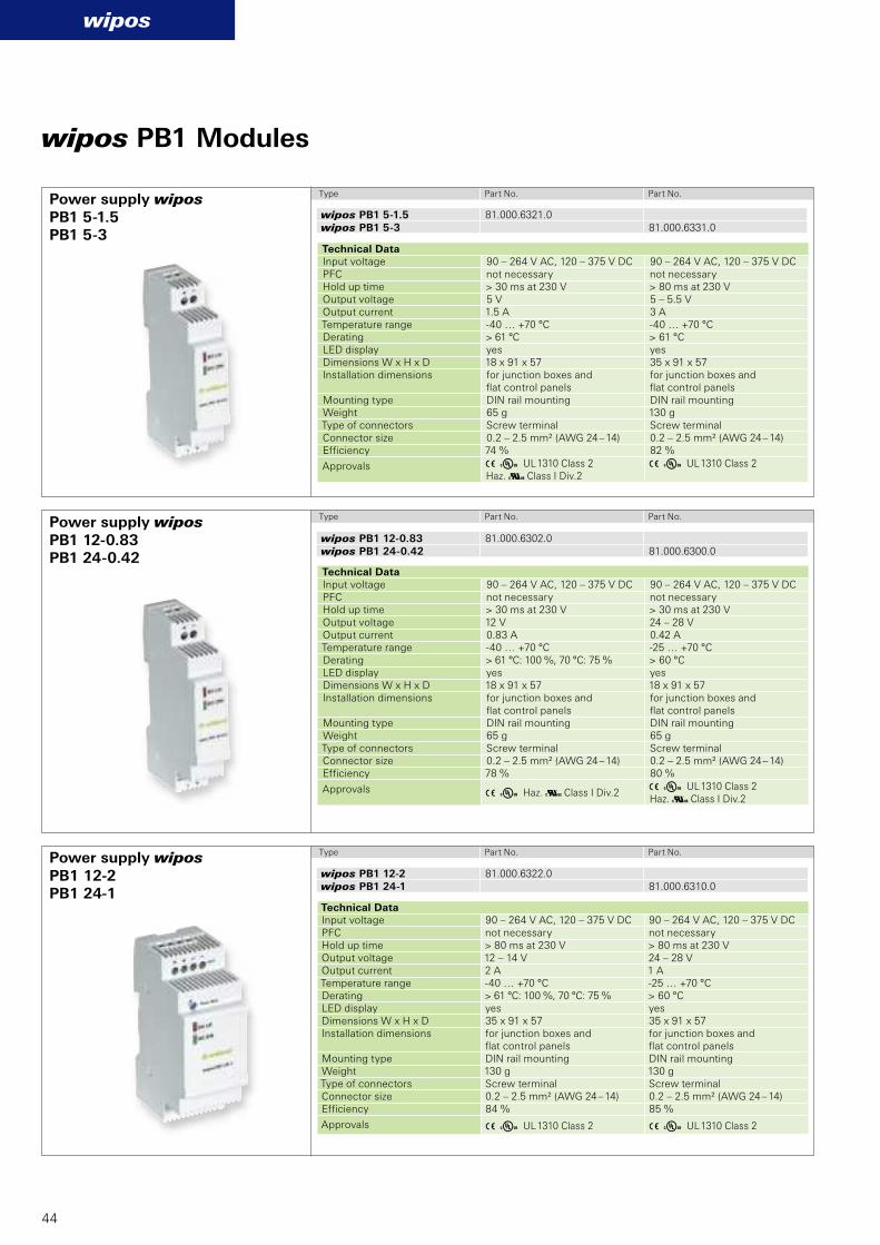
3 Y Haz. a Class I Div.23 Y UL 1310 Class 2Haz. a Class I Div.2
3 Y UL 1310 Class 2Haz. a Class I Div.2
3 Y UL 1310 Class 2
3 Y UL 1310 Class 2 3 Y UL 1310 Class 2
wipos PB1 12-0.83 81.000.6302.0wipos PB1 24-0.42 81.000.6300.0
wipos PB1 5-1.5 81.000.6321.0wipos PB1 5-3 81.000.6331.0
wipos PB1 12-2 81.000.6322.0wipos PB1 24-1 81.000.6310.0
PB1 12-0.83 PB1 24-0.42
PB1 5-1.5PB1 5-3
PB1 12-2PB1 24-1
wipos
44
wipos PB1 Modules
Technical Data Input voltage 90 – 264 V AC, 120 – 375 V DC 90 – 264 V AC, 120 – 375 V DCPFC not necessary not necessary Hold up time > 30 ms at 230 V > 30 ms at 230 V Output voltage 12 V 24 – 28 V Output current 0.83 A 0.42 ATemperature range -40 … +70 °C -25 … +70 °C Derating > 61 °C: 100 %, 70 °C: 75 % > 60 °C LED display yes yesDimensions W x H x D 18 x 91 x 57 18 x 91 x 57Installation dimensions for junction boxes and
fl at control panelsfor junction boxes and fl at control panels
Mounting type DIN rail mounting DIN rail mountingWeight 65 g 65 gType of connectors Screw terminal Screw terminal Connector size 0.2 – 2.5 mm² (AWG 24 – 14) 0.2 – 2.5 mm² (AWG 24 – 14)Effi ciency 78 % 80 %
Approvals
Technical Data Input voltage 90 – 264 V AC, 120 – 375 V DC 90 – 264 V AC, 120 – 375 V DCPFC not necessary not necessary Hold up time > 30 ms at 230 V > 80 ms at 230 V Output voltage 5 V 5 – 5.5 V Output current 1.5 A 3 ATemperature range -40 … +70 °C -40 … +70 °C Derating > 61 °C > 61 °C LED display yes yesDimensions W x H x D 18 x 91 x 57 35 x 91 x 57Installation dimensions for junction boxes and
fl at control panelsfor junction boxes and fl at control panels
Mounting type DIN rail mounting DIN rail mountingWeight 65 g 130 gType of connectors Screw terminal Screw terminal Connector size 0.2 – 2.5 mm² (AWG 24 – 14) 0.2 – 2.5 mm² (AWG 24 – 14)Effi ciency 74 % 82 %
Approvals
Technical Data Input voltage 90 – 264 V AC, 120 – 375 V DC 90 – 264 V AC, 120 – 375 V DCPFC not necessary not necessary Hold up time > 80 ms at 230 V > 80 ms at 230 V Output voltage 12 – 14 V 24 – 28 V Output current 2 A 1 ATemperature range -40 … +70 °C -25 … +70 °C Derating > 61 °C: 100 %, 70 °C: 75 % > 60 °C LED display yes yesDimensions W x H x D 35 x 91 x 57 35 x 91 x 57Installation dimensions for junction boxes and
fl at control panelsfor junction boxes and fl at control panels
Mounting type DIN rail mounting DIN rail mountingWeight 130 g 130 gType of connectors Screw terminal Screw terminal Connector size 0.2 – 2.5 mm² (AWG 24 – 14) 0.2 – 2.5 mm² (AWG 24 – 14)Effi ciency 84 % 85 %
Approvals
Power supply wipos
Power supply wipos
Power supply wipos
Type Part No. Part No.
Type Part No. Part No.
Type Part No. Part No.
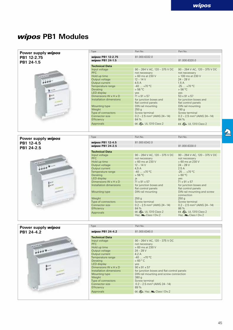
wipos PB1 12-4.5 81.000.6342.0
wipos PB1 24-2.5 81.000.6330.0
3 Y Haz. a Class I Div.2
3 Y UL 1310 Class 2Haz. a Class I Div.2
3 Y UL 1310 Class 2Haz. a Class I Div.2
wipos PB1 24-4.2 81.000.6340.0
PB1 12-4.5PB1 24-2.5
PB1 24-4.2
3 Y UL 1310 Class 2 3 Y UL 1310 Class 2
wipos PB1 12-2.75 81.000.6332.0
wipos PB1 24-1.5 81.000.6320.0PB1 12-2.75PB1 24-1.5
wipos
45
Technical Data Input voltage 90 – 264 V AC, 120 – 375 V DC PFC not necessary Hold up time > 60 ms at 230 V Output voltage 24 – 28 V Output current 4.2 ATemperature range -40 … +70 °C Derating > 60 ° C LED display yesDimensions W x H x D 90 x 91 x 57Installation dimensions for junction boxes and fl at control panelsMounting type DIN rail mounting and screw connectionWeight 380 gType of connectors Screw terminal Connector size 0.2 – 2.5 mm² (AWG 24 – 14)Effi ciency 89 %
Approvals
Technical Data Input voltage 90 – 264 V AC, 120 – 375 V DC 90 – 264 V AC, 120 – 375 V DC PFC not necessary not necessary Hold up time > 60 ms at 230 V > 60 ms at 230 V Output voltage 12 – 14 V 24 – 28 V Output current 4,5 A 2.5 ATemperature range -40 … +70 °C -25 … +70 °C Derating > 56 °C > 60 °C LED display ja yesDimensions W x H x D 71 x 91 x 57 71 x 91 x 57Installation dimensions for junction boxes and
fl at control panelsfor junction boxes and fl at control panels
Mounting type DIN rail mounting DIN rail mounting and screw connection
Weight 250 g 250 gType of connectors Screw terminal Screw terminal Connector size 0.2 – 2.5 mm² (AWG 24 – 14) 0.2 – 2.5 mm² (AWG 24 – 14)Effi ciency 84 % 86 %
Approvals
wipos PB1 Modules
Power supply wipos
Power supply wipos Type Part No.
Type Part No. Part No.
Technical Data Input voltage 90 – 264 V AC, 120 – 375 V DC 90 – 264 V AC, 120 – 375 V DC PFC not necessary not necessary Hold up time > 60 ms at 230 V > 100 ms at 230 V Output voltage 12 – 14 V 24 – 28 V Output current 4.5 A 1.5 ATemperature range -40 … +70 °C -25 … +70 °C Derating > 56 °C > 56 °C LED display yes yesDimensions W x H x D 71 x 91 x 57 53 x 91 x 57Installation dimensions for junction boxes and
fl at control panelsfor junction boxes and fl at control panels
Mounting type DIN rail mounting DIN rail mountingWeight 250 g 190 gType of connectors Screw terminal Screw terminal Connector size 0.2 – 2.5 mm² (AWG 24 – 14) 0.2 – 2.5 mm² (AWG 24 – 14)Effi ciency 84 % 84 %
Approvals
Power supply wipos Type Part No. Part No.
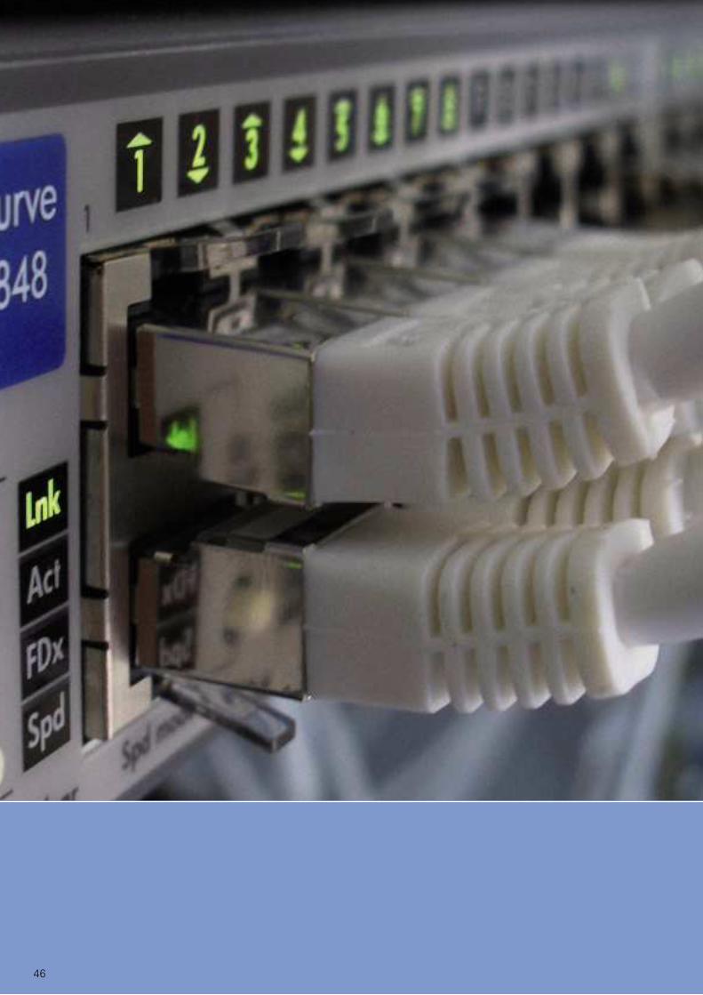
46

47
interfacewienet
Ethernet connections have be-
come part of many areas of life.
This global standard is also
making inroads into automation
technology. Ethernet switches
have become quite common for
safe networking and coupling
between machines, or inside the
system. They manage the data
flow in an effective and target-
oriented manner. The devices are
designed to be very robust and are
optimally suited to harsh industrial
environments.
Industrial Ethernet switchesSafe and fast communication for your process.
Benefi ts:
n Redundant power supply
n Full compatibility according to
IEEE 802.3, including autocrossing,
autonegotiation, autosensing, auto-
polarity
n Complete diagnostics display
via various LEDs
n Compact design
n DIN rail mounting or screw
connection
n Robust designs
n High degree of protection
(IP40)
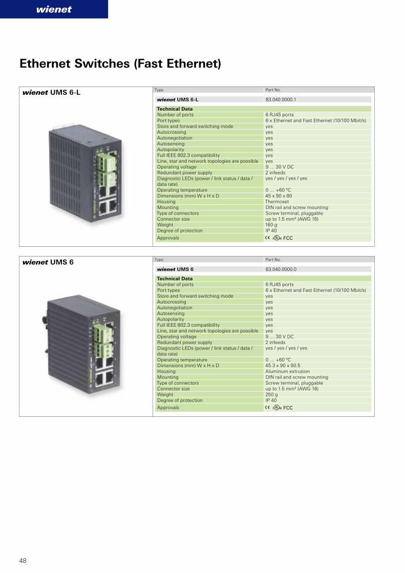
wienet UMS 6-L 83.040.0000.1
wienet UMS 6 83.040.0000.0
wienet UMS 6-L
wienet UMS 6
wienet
48
Ethernet Switches (Fast Ethernet)
Type Part No.
Technical Data Number of ports 6 RJ45 portsPort types 6 x Ethernet and Fast Ethernet (10/100 Mbit/s) Store and forward switching mode yesAutocrossing yesAutonegotiation yesAutosensing yesAutopolarity yesFull IEEE 802.3 compatibility yesLine, star and network topologies are possible yesOperating voltage 9 … 30 V DCRedundant power supply 2 infeedsDiagnostic LEDs (power / link status / data / data rate)
yes / yes / yes / yes
Operating temperature 0 … +60 ºCDimensions (mm) W x H x D 45 x 90 x 80Housing Thermoset Mounting DIN rail and screw mountingType of connectors Screw terminal, pluggableConnector size up to 1.5 mm² (AWG 16)Weight 160 gDegree of protection IP 40
Approvals A E FCC
Type Part No.
Technical Data Number of ports 6 RJ45 portsPort types 6 x Ethernet and Fast Ethernet (10/100 Mbit/s) Store and forward switching mode yesAutocrossing yesAutonegotiation yesAutosensing yesAutopolarity yesFull IEEE 802.3 compatibility yesLine, star and network topologies are possible yesOperating voltage 9 … 30 V DCRedundant power supply 2 infeedsDiagnostic LEDs (power / link status / data / data rate)
yes / yes / yes / yes
Operating temperature 0 … +60 ºCDimensions (mm) W x H x D 45.3 x 90 x 90.5Housing Aluminum extrusionMounting DIN rail and screw mountingType of connectors Screw terminal, pluggableConnector size up to 1.5 mm² (AWG 16)Weight 250 gDegree of protection IP 40
Approvals A E FCC
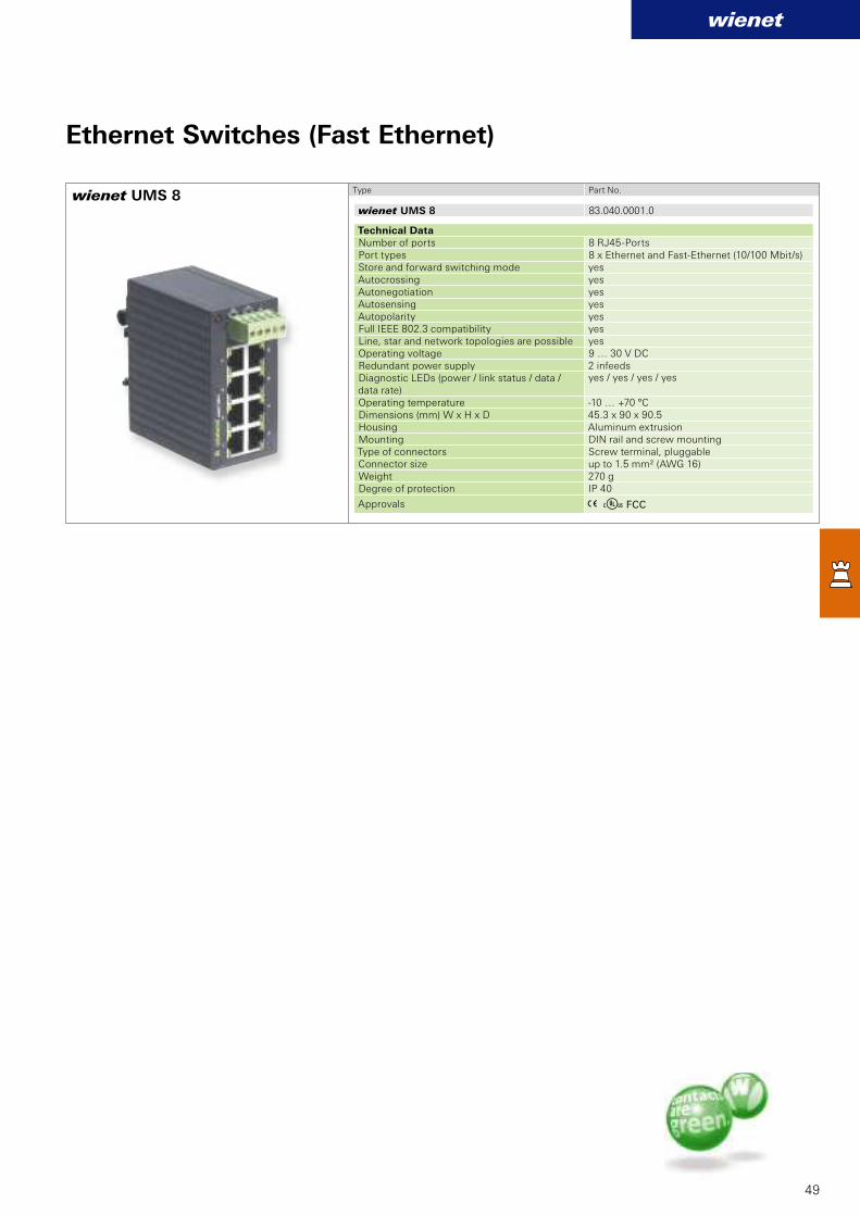
wienet UMS 8 83.040.0001.0
wienet UMS 8
wienet
49
Ethernet Switches (Fast Ethernet)
Type Part No.
Technical Data Number of ports 8 RJ45-PortsPort types 8 x Ethernet and Fast-Ethernet (10/100 Mbit/s) Store and forward switching mode yesAutocrossing yesAutonegotiation yesAutosensing yesAutopolarity yesFull IEEE 802.3 compatibility yesLine, star and network topologies are possible yesOperating voltage 9 … 30 V DCRedundant power supply 2 infeedsDiagnostic LEDs (power / link status / data / data rate)
yes / yes / yes / yes
Operating temperature -10 … +70 °CDimensions (mm) W x H x D 45.3 x 90 x 90.5Housing Aluminum extrusionMounting DIN rail and screw mountingType of connectors Screw terminal, pluggableConnector size up to 1.5 mm² (AWG 16)Weight 270 gDegree of protection IP 40
Approvals A E FCC

wienet UMS 8-2G 83.040.0103.0
wienet UMS 8-2G
wienet UMS 8-G 83.040.0106.0
wienet UMS 8-G
wienet
50
Ethernet Switches (Giga Ethernet)
Type Part No.
Technical Data Number of ports 10 RJ45-Ports
Port types8 x Ethernet and Fast-Ethernet (10/100 Mbit/s) 2 x Giga-Ethernet (10/100/1000 Mbit/s)
Store and forward switching mode yesAutocrossing yesAutonegotiation yesAutosensing yesAutopolarity yesFull IEEE 802.3 compatibility yesLine, star and network topologies are possible yesOperating voltage 12 … 48 V DCRedundant power supply 2 infeeds
Diagnostic LEDs (power / link status / data / data rate)
yes / yes / yes / yes
Operating temperature -40 … +70 °CDimensions (mm) W x H x D 54 x 146 x 130.5Housing Aluminum extrusionMounting DIN rail and screw mountingType of connectors Screw terminal, pluggableConnector size up to 1.5 mm² (AWG 16)Weight 1000 gDegree of protection IP 40
Approvals A E FCC
Type Part No.
Technical Data Number of ports 8 x RJ45 Port types 6 x Giga-Ethernet (10/100/1000 Mbit/s)Store and forward switching mode yesAutocrossing yesAutonegotiation yesAutosensing yesAutopolarity yesFull IEEE 802.3 compatibility yesLine, star and network topologies are possible yesOperating voltage 9 … 48 V DCRedundant power supply 2 infeeds
Diagnostic LEDs (power / link status / data / data rate)
yes / yes / yes / yes
Operating temperature -10 … +70 °C Dimensions (mm) W x H x D 45.3 x 90 x 90.5 Housing MetalMounting DIN rail and screw mountingType of connectors Screw terminal, pluggableConnector size 0.2 – 1.5 mm² (AWG 24 – 16)Weight 255 gDegree of protection IP 50
Approvals A E FCC
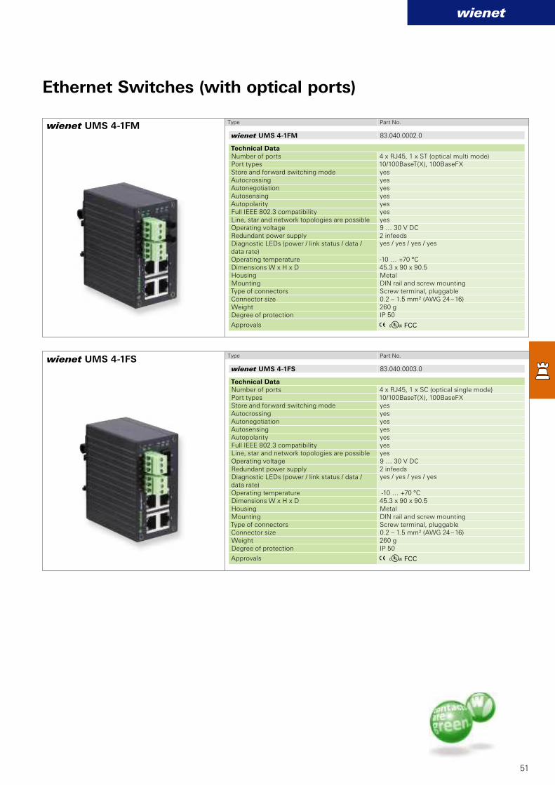
wienet UMS 4-1FM 83.040.0002.0
wienet UMS 4-1FS 83.040.0003.0
wienet UMS 4-1FM
wienet UMS 4-1FS
wienet
51
Ethernet Switches (with optical ports)
Type Part No.
Technical Data Number of ports 4 x RJ45, 1 x ST (optical multi mode)Port types 10/100BaseT(X), 100BaseFXStore and forward switching mode yesAutocrossing yes Autonegotiation yes Autosensing yesAutopolarity yesFull IEEE 802.3 compatibility yesLine, star and network topologies are possible yesOperating voltage 9 … 30 V DCRedundant power supply 2 infeedsDiagnostic LEDs (power / link status / data / data rate)
yes / yes / yes / yes
Operating temperature -10 … +70 °CDimensions W x H x D 45.3 x 90 x 90.5 Housing MetalMounting DIN rail and screw mountingType of connectors Screw terminal, pluggableConnector size 0.2 – 1.5 mm² (AWG 24 – 16)Weight 260 gDegree of protection IP 50
Approvals A E FCC
Type Part No.
Technical Data Number of ports 4 x RJ45, 1 x SC (optical single mode)Port types 10/100BaseT(X), 100BaseFXStore and forward switching mode yesAutocrossing yesAutonegotiation yesAutosensing yesAutopolarity yesFull IEEE 802.3 compatibility yesLine, star and network topologies are possible yesOperating voltage 9 … 30 V DCRedundant power supply 2 infeedsDiagnostic LEDs (power / link status / data / data rate)
yes / yes / yes / yes
Operating temperature -10 … +70 °CDimensions W x H x D 45.3 x 90 x 90.5 Housing MetalMounting DIN rail and screw mountingType of connectors Screw terminal, pluggableConnector size 0.2 – 1.5 mm² (AWG 24 – 16)Weight 260 gDegree of protection IP 50
Approvals A E FCC

wienet
52
Applications
n Energy systems
• Wind turbines
• Solar farms
• Biogas cogeneration
systems
• Heat pumps, ...
n Water and waste water
Management
n System monitoring in machine
building
• Washing machines
• Packaging machines
• Compressors, …
n External surveillance camera
n Vending
Telemetry online sales or ticket
machines
n Smart metering
n Mobile Fleet Management

wienet
IpsecHighspeed RouterEDGE
IpsecIpsec SMS
UMTSUMTSOpen VPN HSUPAHSUPA
GS M HSDPAIpsecIpsec Highspeed RouterHighspeed Router
HSPA+
D H CP
RJ45EDGE
SMS
UMTSOpen VPNOpen VPN
GPRS
HSUPA
GS M HSDPA
Highspeed Router
E-MailE-MailIpsecIpsec
Ipsec 21,1 Mbit/s
HSPA+
Open VPN HSDPA
Highspeed RouterSMSSMS
HSPA+
DynDNS
RJ45Open VPNOpen VPNEDGESMSSMSOpen VPNOpen VPN SMSHSDPAHSDPA
UMTSHighspeed RouterHighspeed RouterOpen VPN
SMSSMS
UMTSUMTSHighspeed RouterHighspeed Router
GPRS
HSUPA
IpsecIpsec
G S MDynDNSDynDNS HSDPAHighspeed RouterHighspeed Router
Open VPNOpen VPN Highspeed Router
E-MailGPRSGPRS
IpsecIpsec 21,1 Mbit/s21,1 Mbit/s
IpsecGPRSGPRS21,1 Mbit/sGPRSGPRSHSPA+
GPRSGPRS
Open VPN HSDPA
Highspeed Router21,1 Mbit/s21,1 Mbit/sHSPA+
DynDNSOpen VPNOpen VPN
53
Functionality which convinces
Whether it is about the control of machines,
monitoring of production lines or the co-
ordination of all production areas a permanent
communication between devices is needed
to complete such a complex task. Access
to stored data using wireless networks is
not always possible or safe. Now Wieland
offers with its modern router technology
the possibility of completing such complex
tasks. For example control commands,
level indicators or video signals can now be
transmitted. At download speeds of up to 100
Mbit/s and upload speeds of up to 50 Mbits/s
(depending on the network operator) the
wienet VPN industrial router is sure to cover
the available connectivity options of GPRS up
to LTE. With automatic login wienet VPN
industrial router will always access the fastest
available connection.
Each router has its own IP address and can
be configured through the integrated web
interface.
It supports services such as DHCP, NAT and
DynDNS. The routers communicate directly
or via the control panel to open a secure VPN
connection. The establishment of an IPSec
encrypted tunnel is alternatively possible.
wienet VPN routers are ideal components for
industrial use in conjunction with VPN-service
portals, such as Wie-Service24.
With the arrangement of the ports on the front-
panel and a standard USB port, the wienet
VPN industrial router are extremely user
friendly. A clear statistic of mobile connections
is used for better control. Optionally, the
devices are available with a second SIM card
slot, additional I/O, RS-232, RS-422/RS-485,
M-Bus, second Ethernet interface, Wi-Fi
module or integrated 3 port switch.
wienet VPN Industrial Router –
unlimited M2M communication

3
wienet EDGE ER75iv2f SL - - 83.041.0100.1 -wienet EDGE ER75iv2f SL RS232 RS-232 - 83.041.0101.1 -wienet EDGE ER75iv2f SL RS485/422 RS-485/422 - 83.041.0102.1 -wienet EDGE ER75iv2f SL MBUS M-Bus - 83.041.0103.1 -wienet EDGE ER75iv2f SL IO IO - 83.041.0104.1 -wienet EDGE ER75iv2f SL ETH ETH - 83.041.0105.1 -wienet EDGE ER75iv2f SL WIFI - WI-FI/WLAN 83.041.0106.1 -wienet EDGE ER75iv2f SL RS232 RS232 RS-232 RS-232 83.041.0111.1 -wienet EDGE ER75iv2f SL RS485 RS232 RS-485/422 RS-232 83.041.0112.1 -wienet EDGE ER75iv2f SL MBUS RS232 M-Bus RS-232 83.041.0113.1 -wienet EDGE ER75iv2f SL CNT RS232 IO RS-232 83.041.0114.1 -wienet EDGE ER75iv2f SL ETH RS232 ETH RS-232 83.041.0115.1 -wienet EDGE ER75iv2f SL RS485 RS485 RS-485/422 RS-485/422 83.041.0122.1 -wienet EDGE ER75iv2f SL MBUS RS485 M-Bus RS-485/422 83.041.0123.1 -wienet EDGE ER75iv2f SL CNT RS485 IO RS-485/422 83.041.0124.1 -wienet EDGE ER75iv2f SL ETH RS485 ETH RS-485/422 83.041.0125.1 -wienet EDGE ER75iv2f SL RS232 WIFI RS-232 WI-FI/WLAN 83.041.0161.1 -wienet EDGE ER75iv2f SL RS485 WIFI RS-485/422 WI-FI/WLAN 83.041.0162.1 -wienet EDGE ER75iv2f SL MBUS WIFI M-Bus WI-FI/WLAN 83.041.0163.1 -wienet EDGE ER75iv2f SL CNT WIFI IO WI-FI/WLAN 83.041.0164.1 -wienet EDGE ER75iv2f SL ETH WIFI ETH WI-FI/WLAN 83.041.0165.1 -wienet EDGE ER75iv2f SL 3P 3-port Switch 3-port Switch 83.041.0199.1 -
wienet EDGE ER75iv2 - - 83.041.0000.1 83.041.0000.0wienet EDGE ER75iv2 RS232 RS-232 - 83.041.0001.1 -wienet EDGE ER75iv2 RS485/422 RS-485/422 - 83.041.0002.1 -wienet EDGE ER75iv2 MBUS M-Bus - 83.041.0003.1 -wienet EDGE ER75iv2 CNT 4DI, 2DO, 2AI - 83.041.0004.1 83.041.0004.0wienet EDGE ER75iv2 ETH Ethernet - 83.041.0005.1 83.041.0005.0
wienet
54
EDGE mobile router „Basic“wienet EDGE ER75i v2
EDGE mobil router „Full“wienet EDGE ER75i v2f SL
Type Part No. Part No.
Type Part No. Part No.
Industrial Mobile Router – GSM / GPRS / EDGE
• 1x SIM-card-slot
• 1x RJ45-Port extension
• Inclusive antenna
• Inclusive RJ45-Patch cable
• Inclusive DIN Rail clip
• Plastic or metal housing
• 2x SIM-card-slot
• 2x RJ45-Port extension
• Inclusive antenna
• Inclusive RJ45-Patch cable
• Inclusive DIN Rail clip
• Plastic or metal housing
Technical Data
Housing Aluminium PlasticDimensions (mm) W x H x D 42 x 113 x 81 42 x 113 x 76Weight 280 g 220 gTransmission GSM/GPRS/EDGE (Class 10)Frequency bands 850/900/1800/1900 MHzSIM-card-slots 1RJ45-extension-ports 1Interfaces Ethernet 10/100 Mbit/s; USB 2.0 Type A (Host);
1x Digital In / 1x Digital OutMax. Download/Upload 236 Kbit/s / 118,4 Kbit/sVPN-Client for encrypted connection to the control center
IPSec Client/Server; OpenVPN Client/Server; L2TP; PPTP
Mounting DIN-rail or tableOperating voltage 10 - 30 V DCOperating temperature -30 … +60°CAntenna External GSM-antenna (SMA - 50 Ohm)ApprovalsNorms EN 301 511, v 9.0.2; EN 301 908-1&2, v 3.2.1; ETSI EN 301
489-1 V1.8.1; EN 60950-1:06 ed. 2 + A11:09
Functions
Support of NAT/PAT and X.509Firewall (SPI)VPN: OpenVPN, IPsec, L2TP, GREEasy web interface, DHCP, DynDNS, VRRP; Dial-inRouter-control by SMSComprehensive mobile statistic optionsData volume-/roaming-control by SMSStatus information by SNMP and SMSStatus by LEDFTPLinux based Operating System: ability to integrate their own applications
EDGE mobile router basic version Port 1 Port 2 Aluminium Plastic
EDGE mobil router full version Port 1 Port 2 Aluminium Plastic
Technical Data
SIM-card-slots 2
RJ45-extension-ports 2
Further technical data see basic version
Functions
see basic version
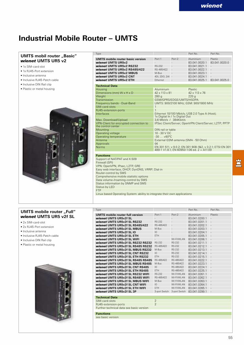
3
wienet UMTS UR5v2 - - 83.041.0020.1 83.041.0020.0wienet UMTS UR5v2 RS232 RS-232 - 83.041.0021.1 -wienet UMTS UR5v2 RS485/422 RS-485/422 - 83.041.0022.1 -wienet UMTS UR5v2 MBUS M-Bus - 83.041.0023.1 -wienet UMTS UR5v2 CNT 4DI, 2DO, 2AI - 83.041.0024.1 -wienet UMTS UR5v2 ETH Ethernet - 83.041.0025.1 83.041.0025.0
wienet UMTS UR5v2f SL - - 83.041.0200.1 -wienet UMTS UR5v2f SL RS232 RS-232 - 83.041.0201.1 -wienet UMTS UR5v2f SL RS485/422 RS-485/422 - 83.041.0202.1 -wienet UMTS UR5v2f SL MBUS M-Bus - 83.041.0203.1 -wienet UMTS UR5v2f SL IO IO - 83.041.0204.1 -wienet UMTS UR5v2f SL ETH ETH - 83.041.0205.1 -wienet UMTS UR5v2f SL WIFI - WI-FI/WLAN 83.041.0206.1 -wienet UMTS UR5v2f SL RS232 RS232 RS-232 RS-232 83.041.0211.1 -wienet UMTS UR5v2f SL RS485 RS232 RS-485/422 RS-232 83.041.0212.1 -wienet UMTS UR5v2f SL MBUS RS232 M-Bus RS-232 83.041.0213.1 -wienet UMTS UR5v2f SL CNT RS232 IO RS-232 83.041.0214.1 -wienet UMTS UR5v2f SL ETH RS232 ETH RS-232 83.041.0215.1 -wienet UMTS UR5v2f SL RS485 RS485 RS-485/422 RS-485/422 83.041.0222.1 -wienet UMTS UR5v2f SL MBUS RS485 M-Bus RS-485/422 83.041.0223.1 -wienet UMTS UR5v2f SL CNT RS485 IO RS-485/422 83.041.0224.1 -wienet UMTS UR5v2f SL ETH RS485 ETH RS-485/422 83.041.0225.1 -wienet UMTS UR5v2f SL RS232 WIFI RS-232 WI-FI/WLAN 83.041.0261.1 -wienet UMTS UR5v2f SL RS485 WIFI RS-485/422 WI-FI/WLAN 83.041.0262.1 -wienet UMTS UR5v2f SL MBUS WIFI M-Bus WI-FI/WLAN 83.041.0263.1 -wienet UMTS UR5v2f SL CNT WIFI IO WI-FI/WLAN 83.041.0264.1 -wienet UMTS UR5v2f SL ETH WIFI ETH WI-FI/WLAN 83.041.0265.1 -wienet UMTS UR5v2f SL 3P 3-port Switch 3-port Switch 83.041.0299.1 -
wienet
55
UMTS mobil router „Basic“wienet UMTS UR5 v2
UMTS mobile router „Full“wienet UMTS UR5 v2f SL
Type Part No. Part No.
Type Part No. Part No.
Industrial Mobile Router – UMTS
• 1x SIM-card-slot
• 1x RJ45-Port extension
• Inclusive antenna
• Inclusive RJ45-Patch cable
• Inclusive DIN Rail clip
• Plastic or metal housing
• 2x SIM-card-slot
• 2x RJ45-Port extension
• Inclusive antenna
• Inclusive RJ45-Patch cable
• Inclusive DIN Rail clip
• Plastic or metal housing
Technical Data
Housing Aluminium PlasticDimensions (mm) W x H x D 42 x 113 x 81 42 x 113 x 76Weight 280 g 220 gTransmission GSM/GPRS/EDGE/UMTS/HSDPAFrequency bands - Dual-Band UMTS: 900/2100 MHz; GSM: 900/1800 MHzSIM-card-slots 1RJ45-extension-ports 1Interfaces Ethernet 10/100 Mbit/s; USB 2.0 Type A (Host);
1x Digital In / 1x Digital OutMax. Download/Upload 3,6 Mbit/s / 384Kbit/sVPN-Client for encrypted connection to the control center
IPSec Client/Server; OpenVPN Client/Server; L2TP; PPTP
Mounting DIN-rail or tableOperating voltage 10 - 30 V DCOperating temperature -30 … +60°CAntenna External GSM-antenna (SMA - 50 Ohm)ApprovalsNorms EN 301 511, v 9.0.2; EN 301 908-1&2, v 3.2.1; ETSI EN 301
489-1 V1.8.1; EN 60950-1:06 ed. 2 + A11:09
Functions
Support of NAT/PAT and X.509Firewall (SPI)VPN: OpenVPN, IPsec, L2TP, GREEasy web interface, DHCP, DynDNS, VRRP; Dial-inRouter-control by SMSComprehensive mobile statistic optionsData volume-/roaming-control by SMSStatus information by SNMP and SMSStatus by LEDFTPLinux based Operating System: ability to integrate their own applications
UMTS mobile router basic version Port 1 Port 2 Aluminium Plastic
UMTS mobile router full version Port 1 Port 2 Aluminium Plastic
Technical Data
SIM-card-slots 2
RJ45-extension-ports 2
Further technical data see basic version
Functions
see basic version
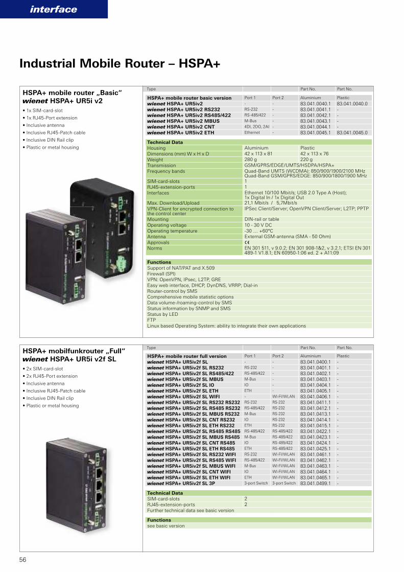
3
wienet HSPA+ UR5iv2f SL - - 83.041.0400.1 -wienet HSPA+ UR5iv2f SL RS232 RS-232 - 83.041.0401.1 -wienet HSPA+ UR5iv2f SL RS485/422 RS-485/422 - 83.041.0402.1 -wienet HSPA+ UR5iv2f SL MBUS M-Bus - 83.041.0403.1 -wienet HSPA+ UR5iv2f SL IO IO - 83.041.0404.1 -wienet HSPA+ UR5iv2f SL ETH ETH - 83.041.0405.1 -wienet HSPA+ UR5iv2f SL WIFI - WI-FI/WLAN 83.041.0406.1 -wienet HSPA+ UR5iv2f SL RS232 RS232 RS-232 RS-232 83.041.0411.1 -wienet HSPA+ UR5iv2f SL RS485 RS232 RS-485/422 RS-232 83.041.0412.1 -wienet HSPA+ UR5iv2f SL MBUS RS232 M-Bus RS-232 83.041.0413.1 -wienet HSPA+ UR5iv2f SL CNT RS232 IO RS-232 83.041.0414.1 -wienet HSPA+ UR5iv2f SL ETH RS232 ETH RS-232 83.041.0415.1 -wienet HSPA+ UR5iv2f SL RS485 RS485 RS-485/422 RS-485/422 83.041.0422.1 -wienet HSPA+ UR5iv2f SL MBUS RS485 M-Bus RS-485/422 83.041.0423.1 -wienet HSPA+ UR5iv2f SL CNT RS485 IO RS-485/422 83.041.0424.1 -wienet HSPA+ UR5iv2f SL ETH RS485 ETH RS-485/422 83.041.0425.1 -wienet HSPA+ UR5iv2f SL RS232 WIFI RS-232 WI-FI/WLAN 83.041.0461.1 -wienet HSPA+ UR5iv2f SL RS485 WIFI RS-485/422 WI-FI/WLAN 83.041.0462.1 -wienet HSPA+ UR5iv2f SL MBUS WIFI M-Bus WI-FI/WLAN 83.041.0463.1 -wienet HSPA+ UR5iv2f SL CNT WIFI IO WI-FI/WLAN 83.041.0464.1 -wienet HSPA+ UR5iv2f SL ETH WIFI ETH WI-FI/WLAN 83.041.0465.1 -wienet HSPA+ UR5iv2f SL 3P 3-port Switch 3-port Switch 83.041.0499.1 -
wienet HSPA+ UR5iv2 - - 83.041.0040.1 83.041.0040.0wienet HSPA+ UR5iv2 RS232 RS-232 - 83.041.0041.1 -wienet HSPA+ UR5iv2 RS485/422 RS-485/422 - 83.041.0042.1 -wienet HSPA+ UR5iv2 MBUS M-Bus - 83.041.0043.1 -wienet HSPA+ UR5iv2 CNT 4DI, 2DO, 2AI - 83.041.0044.1 -wienet HSPA+ UR5iv2 ETH Ethernet - 83.041.0045.1 83.041.0045.0
interface
56
HSPA+ mobile router „Basic“ wienet HSPA+ UR5i v2
HSPA+ mobilfunkrouter „Full“wienet HSPA+ UR5i v2f SL
Type Part No. Part No.
Type Part No. Part No.
Industrial Mobile Router – HSPA+
• 1x SIM-card-slot
• 1x RJ45-Port extension
• Inclusive antenna
• Inclusive RJ45-Patch cable
• Inclusive DIN Rail clip
• Plastic or metal housing
• 2x SIM-card-slot
• 2x RJ45-Port extension
• Inclusive antenna
• Inclusive RJ45-Patch cable
• Inclusive DIN Rail clip
• Plastic or metal housing
Technical Data
Housing Aluminium Plastic
Dimensions (mm) W x H x D 42 x 113 x 81 42 x 113 x 76
Weight 280 g 220 g
Transmission GSM/GPRS/EDGE/UMTS/HSDPA/HSPA+
Frequency bands Quad-Band UMTS (WCDMA): 850/900/1900/2100 MHzQuad-Band GSM/GPRS/EDGE: 850/900/1800/1900 MHz
SIM-card-slots 1
RJ45-extension-ports 1
Interfaces Ethernet 10/100 Mbit/s; USB 2.0 Type A (Host); 1x Digital In / 1x Digital Out
Max. Download/Upload 21,1 Mbit/s / 5,7Mbit/s
VPN-Client for encrypted connection to the control center
IPSec Client/Server; OpenVPN Client/Server; L2TP; PPTP
Mounting DIN-rail or table
Operating voltage 10 - 30 V DCOperating temperature -30 … +60°CAntenna External GSM-antenna (SMA - 50 Ohm)
ApprovalsNorms EN 301 511, v 9.0.2; EN 301 908-1&2, v 3.2.1; ETSI EN 301
489-1 V1.8.1; EN 60950-1:06 ed. 2 + A11:09
Functions
Support of NAT/PAT and X.509Firewall (SPI)VPN: OpenVPN, IPsec, L2TP, GREEasy web interface, DHCP, DynDNS, VRRP; Dial-inRouter-control by SMSComprehensive mobile statistic optionsData volume-/roaming-control by SMSStatus information by SNMP and SMSStatus by LEDFTPLinux based Operating System: ability to integrate their own applications
HSPA+ mobile router basic version Port 1 Port 2 Aluminium Plastic
HSPA+ mobile router full version Port 1 Port 2 Aluminium Plastic
Technical Data
SIM-card-slots 2
RJ45-extension-ports 2
Further technical data see basic version
Functions
see basic version

3
wienet LTE LR77v2f SL - - 83.041.0500.1 -wienet LTE LR77v2f SL RS232 RS-232 - 83.041.0501.1 -wienet LTE LR77v2f SL RS485/422 RS-485/422 - 83.041.0502.1 -wienet LTE LR77v2f SL MBUS M-Bus - 83.041.0503.1 -wienet LTE LR77v2f SL IO IO - 83.041.0504.1 -wienet LTE LR77v2f SL ETH ETH - 83.041.0505.1 -wienet LTE LR77v2f SL WIFI - WI-FI/WLAN 83.041.0506.1 -wienet LTE LR77v2f SL RS232 RS232 RS-232 RS-232 83.041.0511.1 -wienet LTE LR77v2f SL RS485 RS232 RS-485/422 RS-232 83.041.0512.1 -wienet LTE LR77v2f SL MBUS RS232 M-Bus RS-232 83.041.0513.1 -wienet LTE LR77v2f SL CNT RS232 IO RS-232 83.041.0514.1 -wienet LTE LR77v2f SL ETH RS232 ETH RS-232 83.041.0515.1 -wienet LTE LR77v2f SL RS485 RS485 RS-485/422 RS-485/422 83.041.0522.1 -wienet LTE LR77v2f SL MBUS RS485 M-Bus RS-485/422 83.041.0523.1 -wienet LTE LR77v2f SL CNT RS485 IO RS-485/422 83.041.0524.1 -wienet LTE LR77v2f SL ETH RS485 ETH RS-485/422 83.041.0525.1 -wienet LTE LR77v2f SL RS232 WIFI RS-232 WI-FI/WLAN 83.041.0561.1 -wienet LTE LR77v2f SL RS485 WIFI RS-485/422 WI-FI/WLAN 83.041.0562.1 -wienet LTE LR77v2f SL MBUS WIFI M-Bus WI-FI/WLAN 83.041.0563.1 -wienet LTE LR77v2f SL CNT WIFI IO WI-FI/WLAN 83.041.0564.1 -wienet LTE LR77v2f SL ETH WIFI ETH WI-FI/WLAN 83.041.0565.1 -wienet LTE LR77v2f SL 3P 3-port Switch 3-port Switch 83.041.0599.1 -
wienet LTE LR77v2 - - 83.041.0050.1 83.041.0050.0wienet LTE LR77v2 RS232 RS-232 - 83.041.0051.1 -wienet LTE LR77v2 RS485/422 RS-485/422 - 83.041.0052.1 -wienet LTE LR77v2 MBUS M-Bus - 83.041.0053.1 -wienet LTE LR77v2 CNT 4DI, 2DO, 2AI - 83.041.0054.1 -wienet LTE LR77v2 ETH Ethernet - 83.041.0055.1 83.041.0055.0
interface
57
Industrial Mobile Router – LTE 4G
LTE mobile router 4G „Basic“ wienet LTE LR77 v2 SL
LTE mobile router 4G „Full“ wienet LTE LR77 v2f SL
Type Part No. Part No.
Type Part No. Part No.
• 1x SIM-card-slot
• 1x RJ45-Port extension
• Inclusive antenna
• Inclusive RJ45-Patch cable
• Inclusive DIN Rail clip
• Plastic or metal housing
• 2x SIM-card-slot
• 2x RJ45-Port extension
• Inclusive antenna
• Inclusive RJ45-Patch cable
• Inclusive DIN Rail clip
• Plastic or metal housing
Technical Data
Housing Aluminium Plastic
Dimensions (mm) W x H x D 42 x 113 x 81 42 x 113 x 76
Weight 280 g 220 g
Transmission GSM/GPRS/EDGE/UMTS/HSDPA/HSPA+/LTE
Frequency bands LTE: 800/900/1800/2100/2600 MHz; UMTS: 900/2100 MHz; GSM/GPRS/EDGE: 900/1800/1900 MHz
SIM-card-slots 1
RJ45-extension-ports 1
Interfaces Ethernet 10/100 Mbit/s; USB 2.0 Type A (Host); 1x Digital In / 1x Digital Out
Max. Download/Upload 100 Mbit/s / 50 Mbit/sVPN-Client for encrypted connection to the control center
IPSec Client/Server; OpenVPN Client/Server; L2TP; PPTP
Mounting DIN-rail or table
Operating voltage 10 - 30 V DCOperating temperature -30 … +60°CAntenna External GSM-antenna (SMA - 50 Ohm)
ApprovalsNorms EN 301 511, v 9.0.2; EN 301 908-1&2, v 3.2.1; ETSI EN 301
489-1 V1.8.1; EN 60950-1:06 ed. 2 + A11:09
Functions
Support of NAT/PAT and X.509Firewall (SPI)VPN: OpenVPN, IPsec, L2TP, GREEasy web interface, DHCP, DynDNS, VRRP; Dial-inRouter-control by SMSComprehensive mobile statistic optionsData volume-/roaming-control by SMSStatus information by SNMP and SMSStatus by LEDFTPLinux based Operating System: ability to integrate their own applications
LTE-Mobilfunkrouter 4G basic version Port 1 Port 2 Aluminium Plastic
LTE mobile router 4G full version Port 1 Port 2 Aluminium Plastic
Technical Data
SIM-card-slots 2
RJ45-extension-ports 2
Further technical data see basic version
Functions
see basic version

3
wienet GXS606 83.041.0210.0
wienet GXR623 83.041.0200.0
wienet LAN XR5iv2 ETH Ethernet - 83.041.0065.1 83.041.0065.0wienet LAN XR5iv2f SL ETH RS232 Ethernet RS-232 83.041.0071.1 -wienet LAN XR5iv2f SL ETH RS485 Ethernet RS-485 83.041.0072.1 -wienet LAN XR5iv2f SL RS232 WIFI RS-232 WI-FI/WLAN 83.041.0081.1 -wienet LAN XR5iv2f SL RS485 WIFI RS-485 WI-FI/WLAN 83.041.0082.1 -wienet LAN XR5iv2f SL MBUS WIFI M-Bus WI-FI/WLAN 83.041.0083.1 -wienet LAN XR5iv2f SL IO WIFI 4DI, 2DO, 2AI WI-FI/WLAN 83.041.0084.1 -wienet LAN XR5iv2f SL ETH WIFI Ethernet WI-FI/WLAN 83.041.0085.1 -
interface
Typ Bestell-Nr.
58
Type Part No.
Type Part No. Top flat antennawienet GXR623
Omnidirectional rod antenna wienet GXS606 Technical Data
Frequency bandwidth GSM, GPRS, EDGE, UMTS
Connector FME/F
Gain 2.2 dBi
Length of cable 5 m
Dimensions Length of rod approx. 300 mm
Technical Data
Frequency bandwidth GSM, GPRS, EDGE, UMTS
Connector FME/F
Gain 2.2 dBi
Length of cable 2.5 m
Dimensions approx. 75 x 80 x 13 mm
Industrial Router – LAN-to-LAN
Type Part No. Part No.
Technical Data
Housing Aluminium Plastic
Dimensions (mm) W x H x D 42 x 113 x 81 42 x 113 x 76
Weight 280 g 220 g
Transmission LAN-to-LAN, WI-FI/WLAN
RJ45-extension-ports 1 (basic version), 2 (full version)
Interfaces Ethernet 10/100 Mbit/s; USB 2.0 Typ A (Host); 1x Digital In / 1x Digital Out
Max. Download/Upload Fast Ethernet
VPN-Client for encrypted connection to the control center
IPSec Client/Server; L2TP; PPTP
Mounting DIN-rail or table
Operating voltage 10 - 30 V DCOperating temperature -30 … +60°CApprovalsNorms ETSI EN 301 489-1 V1.8.1;
EN 60950-1:06 ed. 2 + A11:09
Functions
Support of NAT/PAT and X.509Firewall (SPI)VPN: OpenVPN, IPsec, L2TP, GREEasy web interface, DHCP, DynDNS, VRRP; Dial-inPPPoE - DSL-Modem SupportStatus by LEDSNMP - Integration to the network managementFTP Linux based Operating System: ability to integrate their own applications
LAN-to-LAN router Port 1 Port 2 Aluminium PlasticLAN-to-LAN router wienet LAN XR5i v2
• inklusive 2xRJ45-Patch cable
• Inclusive DIN Rail clip
• Plastic or metal housing
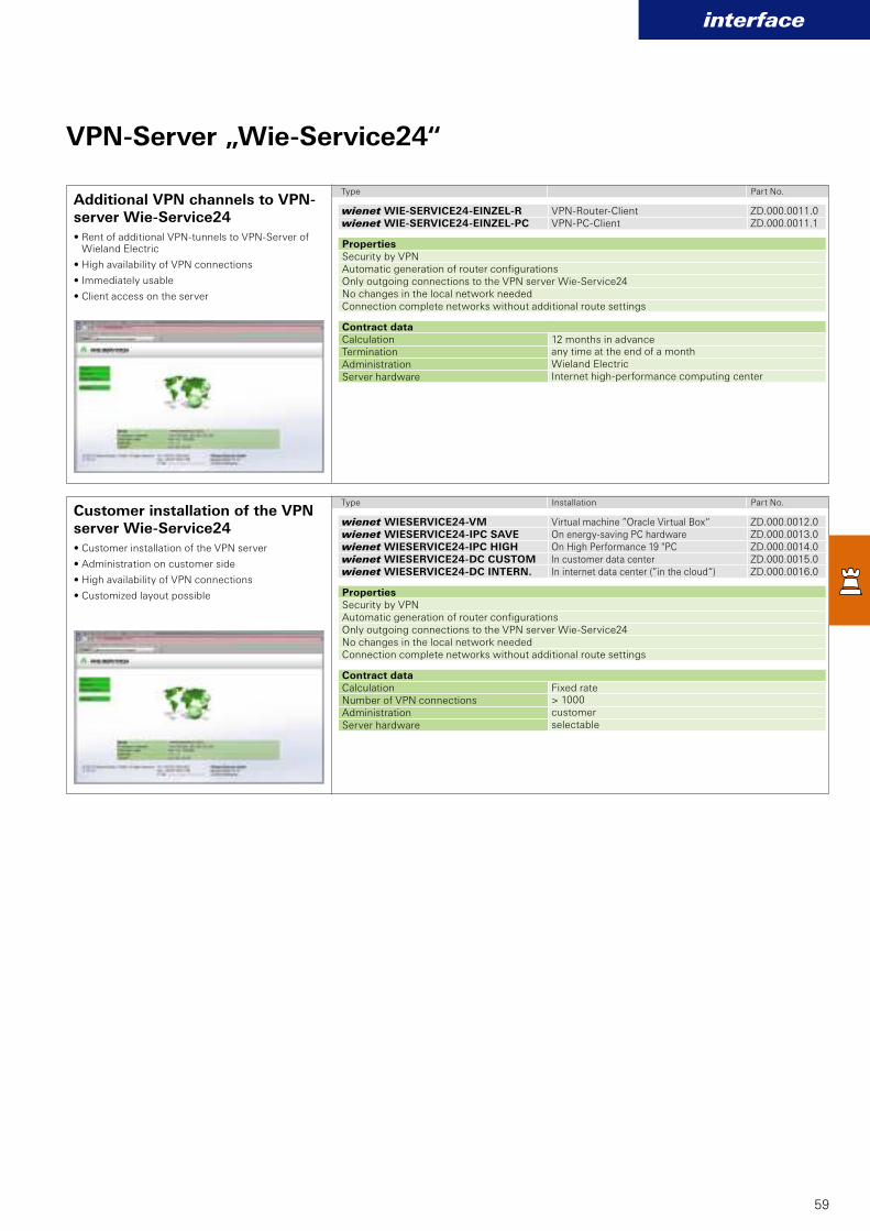
wienet WIESERVICE24-VM ZD.000.0012.0wienet WIESERVICE24-IPC SAVE ZD.000.0013.0wienet WIESERVICE24-IPC HIGH ZD.000.0014.0wienet WIESERVICE24-DC CUSTOM ZD.000.0015.0wienet WIESERVICE24-DC INTERN. ZD.000.0016.0
wienet WIE-SERVICE24-EINZEL-R ZD.000.0011.0wienet WIE-SERVICE24-EINZEL-PC ZD.000.0011.1
interface
59
VPN-Server „Wie-Service24“
Type Part No.
Type Installation Part No.
Properties
Security by VPNAutomatic generation of router configurationsOnly outgoing connections to the VPN server Wie-Service24No changes in the local network neededConnection complete networks without additional route settings
Contract data
Calculation 12 months in advanceTermination any time at the end of a month
Administration Wieland Electric
Server hardware Internet high-performance computing center
Properties
Security by VPNAutomatic generation of router configurationsOnly outgoing connections to the VPN server Wie-Service24No changes in the local network neededConnection complete networks without additional route settings
Contract data
Calculation Fixed rateNumber of VPN connections > 1000
Administration customer
Server hardware selectable
Additional VPN channels to VPN-server Wie-Service24
Customer installation of the VPN server Wie-Service24
• Rent of additional VPN-tunnels to VPN-Server of Wieland Electric
• High availability of VPN connections
• Immediately usable
• Client access on the server
• Customer installation of the VPN server
• Administration on customer side
• High availability of VPN connections
• Customized layout possible
Virtual machine ”Oracle Virtual Box“On energy-saving PC hardwareOn High Performance 19 "PCIn customer data centerIn internet data center (”in the cloud“)
VPN-Router-Client VPN-PC-Client

RJ45EDGE
SMS
Open VPNHSDPA
Open VPN HSDPA
HSPA+
DynDNS
RJ45Open VPNOpen VPNEDGESMSSMSOpen VPNOpen VPN SMSHSDPAHSDPA GPRS
G S MDynDNSDynDNS
Highspeed Router
21,1 Mbit/s
Open VPN HSDPA
HSPA+
DynDNSOpen VPNOpen VPN
wienet
GGGGGGSSSSSS MMMMMMMM
HHHHHHHHSSSSSSSPPPPPPPAAAAAAA
SMS
HHHHHHHHHHHHHHHHHHHHHHHHHHHHHHHHHHHHHHHHHHHHHHHHHHHHHHHHHSSSSSSSSSSSSSSSSSSSSSSSSSSSSSSSSSSSSSSSSSSSSSSSSSSSSSSSSSSSSSSSSSSSSSSSSSSSSSSSSSSSSSSSSSSSSSSSSSSSSSSSSUUUUUUUUUUUUUUUUUUUUUUUUUUUUUUUUUUUUUUUUUUUUUUUUUUUUUUUUUUUUUUUUUUUUUUUUUUUUUUUUUUUUUUUUUUUUUUUUUUUUUUUUUUUUUUUUUUUUUUUUUUUUUUUUPPPPPPPPPPPPPPPPPPPPPPPPPPPPPPPPPPPPPPPPPPPPPPPPPPPPPPPPPPPPPPPPPPPPPPPPPPPPPPPPPPPPPPPPPPPPPPPPPPPPPPPPPAAAAAAAAAAAAAAAAAAAAAAAAAAAAAAAAAAAAAAAAAAAAAAAAAAAAAAAAAAAAAAAAAAAAAAA
Highspeed Router
22222222222211111111111111111111111111 MMMMMMMMMMMMMMMMbit/s
HHHHHHHHHHHHHSSSSSSSSSSSSSSPPPPPPPPPPPPPPAAAAAAAAAAAAAAAAAAAAAAA++++++++++++++++++++
pen VPN HSDPA
Highspeed Routerererererererererer
DGESMSSMSpen pen
UMTSed Routered RouterOpen VPPPPPPPNNNNNNNNNNNNNSS Highspeed hspeed
GPRS
HSUPA
HSDPAHighHigh
E-MMMMMMMMMMMMMMMMMMMaaaaaaaaaaaaaaaaiiiiiiilllllllllll2222211111222221111
I 21,1 Mbit/s
HHHHHHHHSSSSSSSSSSSSSSSSSSSSSSSSSSSSSSSSSSSSSSPA+HigHigHigHigHigHigHigHigHighsp uter2222222211111111,,,,,,,,,11111111 MMMMMMMMMMbi22222221111111,,,,,,,,,11111 MMMMMMMMMbi
HSPA+
60
Wie-Service24More security, more service, simply more
A perfect team
The Wie-Service24 portal is optimized
for the Wieland mobile and LAN-to-
LAN router. It automatically generates
the configuration of the router and
provides it for download. By this
automatic setup possible failures will
be minimized. Wie-Service24 generates
and categorizes certificates for Wieland
router. It regulates within a bigger
group who is able to communicate
with who. The combination of Wie-
Service24 and the Wieland router
enable a fast commissioning and a
highly secure VPN connection.
Advantages
n Security by VPN
n Automatic generation of
router configuration
n Only outgoing connections
towards Wie-Service24 are
necessary
n No changes inside the local
network is necessary
n Interconnection of complete
networks, without additional
routing configuration
n Little coordination with
IT department and easy
commissioning
n Mobile access by Smartphone
or tablet to all devices behind
the router
n directRemote: Direct access
with all internet browser by a
clearly URL
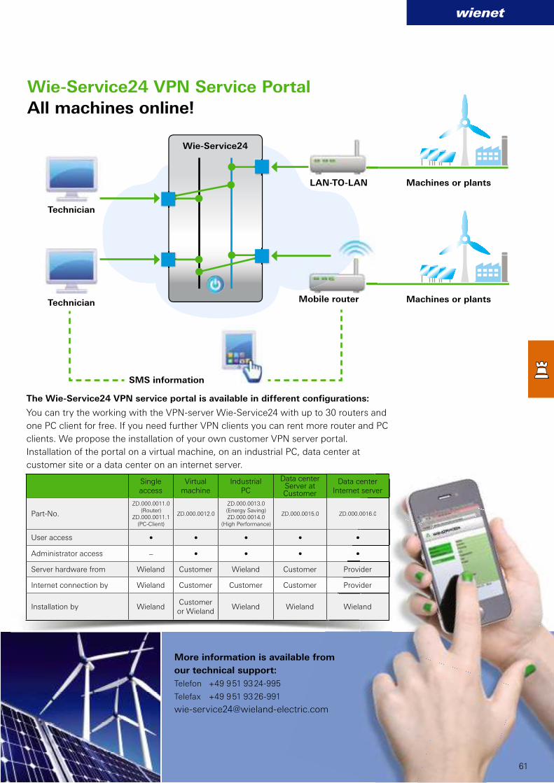
HSPA+Highspeed Router
21,1 Mbit/s
HSPA+21,1 Mbit/s
wienet
ZD.000.0011.0(Router)
ZD.000.0011.1(PC-Client)
ZD.000.0012.0
ZD.000.0013.0 (Energy Saving)ZD.000.0014.0
(High Performance)
ZD.000.0015.0 ZD.000.0016.0
• • • • •
– • • • •
.00
•
•
.0016.0
61
All machines online!
Wie-Service24 VPN Service Portal
The Wie-Service24 VPN service portal is available in different configurations:
You can try the working with the VPN-server Wie-Service24 with up to 30 routers and
one PC client for free. If you need further VPN clients you can rent more router and PC
clients. We propose the installation of your own customer VPN server portal.
Installation of the portal on a virtual machine, on an industrial PC, data center at
customer site or a data center on an internet server.
More information is available from
our technical support:
Telefon +49 9 51 93 24-995
Telefax +49 9 51 93 26-991
Mobile router
Machines or plants
Machines or plants
Technician
SMS information
Wie-Service24
LAN-TO-LAN
Technician
Single access
Virtual machine
IndustrialPC
Data centerServer at Customer
Data centerInternet server
Part-No.
User access
Administrator access
Server hardware from Wieland Customer Wieland Customer Provider
Internet connection by Wieland Customer Customer Customer Provider
Installation by WielandCustomer or Wieland
Wieland Wieland Wieland

62
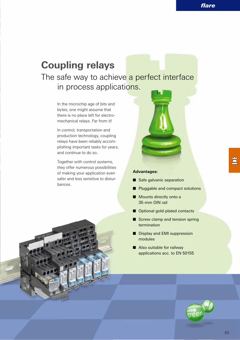
interface
63
flare
In the microchip age of bits and
bytes, one might assume that
there is no place left for electro-
mechanical relays. Far from it!
In control, transportation and
production technology, coupling
relays have been reliably accom-
plishing important tasks for years,
and continue to do so.
Together with control systems,
they offer numerous possibilities
of making your application even
safer and less sensitive to distur-
bances.
Coupling relaysThe safe way to achieve a perfect interface in process applications.
Advantages:
n Safe galvanic separation
n Pluggable and compact solutions
n Mounts directly onto a
35-mm DIN rail
n Optional gold-plated contacts
n Screw clamp and tension spring
termination
n Display and EMI suppression
modules
n Also suitable for railway
applications acc. to EN 50155
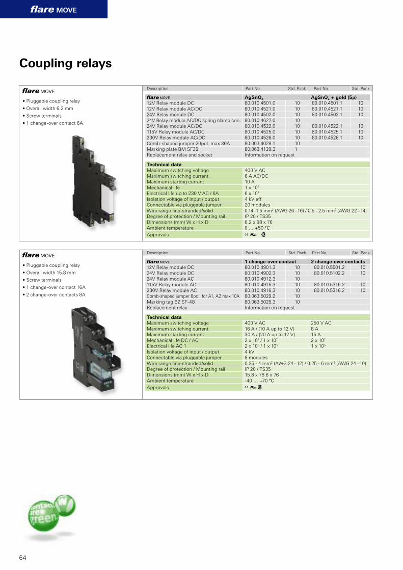
flare MOVE
flare MOVE
flare MOVE
80.010.4901.3 10 80.010.5501.2 1080.010.4902.3 10 80.010.5102.2 1080.010.4912.3 1080.010.4915.3 10 80.010.5315.2 1080.010.4916.3 10 80.010.5316.2 1080.063.5029.2 1080.063.5029.3 10
A Kw
flare MOVE
flare MOVE
80.010.4501.0 10 80.010.4501.1 1080.010.4521.0 10 80.010.4521.1 1080.010.4502.0 10 80.010.4502.1 1080.010.4622.0 1080.010.4522.0 10 80.010.4522.1 1080.010.4525.0 10 80.010.4525.1 1080.010.4526.0 10 80.010.4526.1 1080.063.4029.1 1080.063.4129.3 1
A K w
64
Coupling relays
• Pluggable coupling relay
• Overall width 6.2 mm
• Screw terminals
• 1 change-over contact 6A
• Pluggable coupling relay
• Overall width 15.8 mm
• Screw terminals
• 1 change-over contact 16A
• 2 change-over contacts 8A
Description Part No. Std. Pack Part No. Std. Pack
1 change-over contact 2 change-over contacts
12V Relay module DC24V Relay module DC24V Relay module AC115V Relay module AC230V Relay module ACComb-shaped jumper 8pol. for A1, A2 max 10AMarking tag BZ SF-48Replacement relay Information on request
Technical data
Maximum switching voltage 400 V AC 250 V ACMaximum switching current 16 A / (10 A up to 12 V) 8 AMaximum starting current 30 A / (20 A up to 12 V) 15 AMechanical life DC / AC 2 x 10⁷ / 1 x 10⁷ 2 x 10⁷
Electrical life AC 1 2 x 10⁵ / 1 x 10⁵ 1 x 10⁵
Isolation voltage of input / output 4 kVConnectable via pluggable jumper 8 modulesWire range fi ne-stranded/solid 0.25 - 4 mm2 (AWG 24 – 12) / 0.25 - 6 mm2 (AWG 24 – 10)Degree of protection / Mounting rail IP 20 / TS35Dimensions (mm) W x H x D 15.8 x 78.6 x 76Ambient temperature -40 … +70 °C
Approvals
AgSnO2 AgSnO2 + gold (5µ)
12V Relay module DC12V Relay module AC/DC24V Relay module DC24V Relay module AC/DC spring clamp con.24V Relay module AC/DC115V Relay module AC/DC230V Relay module AC/DCComb-shaped jumper 20pol. max 36AMarking plate BM SF38Replacement relay and socket Information on request
Technical data
Maximum switching voltage 400 V ACMaximum switching current 6 A AC/DCMaximum starting current 10 AMechanical life 1 x 10⁷
Electrical life up to 230 V AC / 6A 6 x 10⁴
Isolation voltage of input / output 4 kV effConnectable via pluggable jumper 20 modulesWire range fi ne-stranded/solid 0.14 -1.5 mm2 (AWG 26 – 16) / 0.5 - 2.5 mm2 (AWG 22 – 14)Degree of protection / Mounting rail IP 20 / TS35Dimensions (mm) W x H x D 6.2 x 88 x 76Ambient temperature 0 … +50 °C
Approvals
Description Part No. Std. Pack Part No. Std. Pack
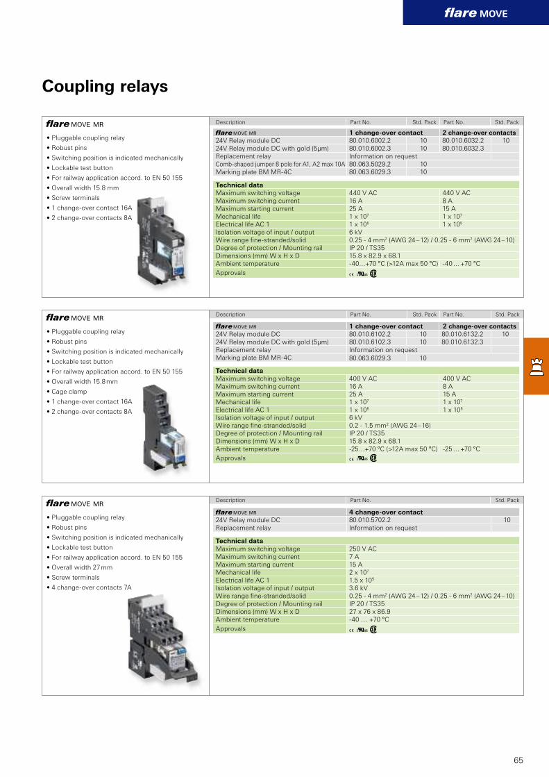
flare MOVE MR
flare MOVE MR
flare MOVE MR
flare MOVE MR
80.010.6002.2 10 80.010.6032.2 1080.010.6002.3 10 80.010.6032.3
80.063.5029.2 1080.063.6029.3 10
AKw
flare MOVE MR
80.010.6102.2 10 80.010.6132.2 1080.010.6102.3 10 80.010.6132.3
80.063.6029.3 10
AKw
flare MOVE MR
80.010.5702.2 10
AKw
flare MOVE
65
Coupling relays
• Pluggable coupling relay
• Robust pins
• Switching position is indicated mechanically
• Lockable test button
• For railway application accord. to EN 50 155
• Overall width 15.8 mm
• Screw terminals
• 1 change-over contact 16A
• 2 change-over contacts 8A
• Pluggable coupling relay
• Robust pins
• Switching position is indicated mechanically
• Lockable test button
• For railway application accord. to EN 50 155
• Overall width 27 mm
• Screw terminals
• 4 change-over contacts 7A
• Pluggable coupling relay
• Robust pins
• Switching position is indicated mechanically
• Lockable test button
• For railway application accord. to EN 50 155
• Overall width 15.8 mm
• Cage clamp
• 1 change-over contact 16A
• 2 change-over contacts 8A
Description Part No. Std. Pack Part No. Std. Pack
Description Part No. Std. Pack Part No. Std. Pack
Description Part No. Std. Pack
1 change-over contact 2 change-over contacts
24V Relay module DC24V Relay module DC with gold (5µm)Replacement relay Information on requestComb-shaped jumper 8 pole for A1, A2 max 10AMarking plate BM MR-4C
Technical data
Maximum switching voltage 440 V AC 440 V ACMaximum switching current 16 A 8 AMaximum starting current 25 A 15 AMechanical life 1 x 10⁷ 1 x 10⁷
Electrical life AC 1 1 x 10⁵ 1 x 10⁵
Isolation voltage of input / output 6 kVWire range fi ne-stranded/solid 0.25 - 4 mm2 (AWG 24 – 12) / 0.25 - 6 mm2 (AWG 24 – 10)Degree of protection / Mounting rail IP 20 / TS35Dimensions (mm) W x H x D 15.8 x 82.9 x 68.1Ambient temperature -40…+70 °C (>12A max 50 °C) -40 … +70 °C
Approvals
1 change-over contact 2 change-over contacts
24V Relay module DC24V Relay module DC with gold (5µm)Replacement relay Information on requestMarking plate BM MR-4C
Technical data
Maximum switching voltage 400 V AC 400 V ACMaximum switching current 16 A 8 AMaximum starting current 25 A 15 AMechanical life 1 x 10⁷ 1 x 10⁷
Electrical life AC 1 1 x 10⁵ 1 x 10⁵
Isolation voltage of input / output 6 kVWire range fi ne-stranded/solid 0.2 - 1.5 mm2 (AWG 24 – 16)Degree of protection / Mounting rail IP 20 / TS35Dimensions (mm) W x H x D 15.8 x 82.9 x 68.1Ambient temperature -25…+70 °C (>12A max 50 °C) -25 … +70 °C
Approvals
4 change-over contact
24V Relay module DCReplacement relay Information on request
Technical data
Maximum switching voltage 250 V ACMaximum switching current 7 AMaximum starting current 15 AMechanical life 2 x 10⁷
Electrical life AC 1 1.5 x 10⁵
Isolation voltage of input / output 3.6 kVWire range fi ne-stranded/solid 0.25 - 4 mm2 (AWG 24 – 12) / 0.25 - 6 mm2 (AWG 24 – 10)Degree of protection / Mounting rail IP 20 / TS35Dimensions (mm) W x H x D 27 x 76 x 86.9Ambient temperature -40 … +70 °C
Approvals

flare
flare
80.010.4106.0 1080.010.4000.0 10 80.010.4100.0 10
80.010.4131.0 1080.010.4141.0 10
Z8.000.0200.8 10Z8.000.0202.3 5Z8.000.0202.4 5Z8.000.0202.1 20Z8.000.0202.2 20Z4.242.5153.0 10
80.010.4005.0 10 80.010.4105.0 10
80.010.4103.0 5
80.010.4120.0 10
80.010.4101.0 10
flare
66
Coupling relays
• Compact coupling relay
• Overall width 6.2 mm
• Screw terminals/ Cage clamp
• 1 change-over contact 6 A
• Compact coupling relay
• Overall width 6.2 mm / 12.4 (2 change-over contacts)
• Screw terminals/ Cage clamp
• Special Type
Description Part No. Std. Pack Part No. Std. Pack
flare MOVE Screw terminal Cage clamp
12V Relay module DC24V Relay module DC115V Relay module AC230V Relay module ACPluggable jumper max 2AJumper for potential distribution redJumper for potential distribution blueEndcaps for jumper, redEndcaps for jumper, blue8 digit marking tag, unmarked, 60 pcs.
Technical data
Maximum switching voltage 250 V AC / 300 V DCMaximum switching current 6 A AC / 2A DCMaximum starting current 10 AMechanical life 1 x 10⁷
Electrical life up to 230V AC / 6A 8 x 10⁴
Isolation voltage of input / output 4 kV eff
Connectable via pluggable jumper 50 modulesWire range fi ne-stranded/solid 0.5 -2.5 mm2 (AWG 22 – 14) /
0.25 - 4 mm2 (AWG 24 – 12)0.25 -1.5 mm2 (AWG 24 – 16) / 0.25 - 2.5 mm2 (AWG 24 – 14)
Degree of protection / Mounting rail IP 20 / TS35Dimensions (mm) W x H x D 6.2 x 89 x 70Ambient temperature 0 … +60 °C
Approvals Aq w h
flare Screw terminal Cage clamp
24V Relay module AC/DC1 change-over contact DC 48V 20mA with gold (3µm)24V Relay module DC2 change-over contact AC 250V 6A AC/DC 300 V 2A DC24V Knife edge disconnect relay AC/DC 1 change-over contact AC 250V 6A / DC 300 V 2 A24V HAND-0-AUTO-Relay1 normally open contact AC 250V 6A / DC 300V 2A
Technical data
Mechanical life 2 x 10⁷
Electrical life up to 230V AC / 6A 6 x 10⁴
Isolation voltage of input / output 4 kVeff
Connectable via pluggable jumper 50 modulesWire range fi ne-stranded/solid 0.5 -2.5 mm2 (AWG 22 – 14) /
0.25 - 4 mm2 (AWG 24 – 12)0.25 -1.5 mm2 (AWG 24 – 16) / 0.25 - 2.5 mm2 (AWG 24 – 14)
Degree of protection / Mounting rail IP 20 / TS35Dimensions (mm) W x H x D 6.2 x 89 x 70 / 12.4 x 89 x 70 (2 change-over contacts) Ambient temperature 0 …. +60 °C 6 mm2
Approvals Aq w h
Description Part No. Std. Pack Part No. Std. Pack
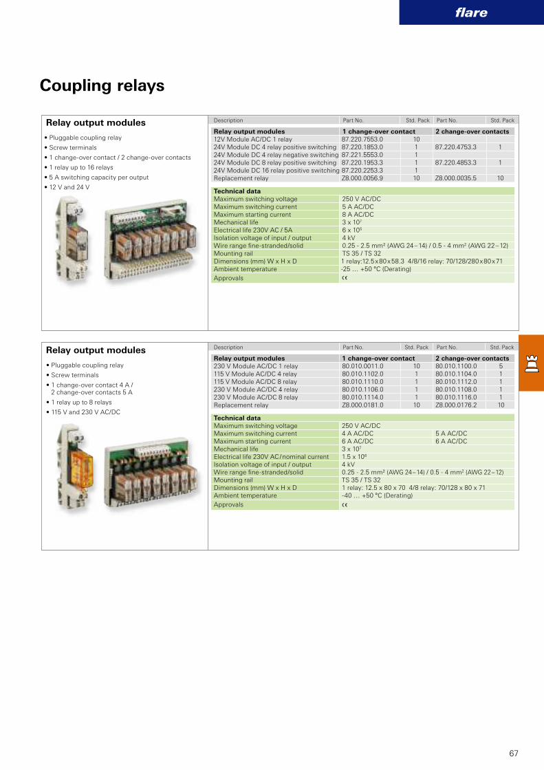
A
A
87.220.7553.0 1087.220.1853.0 1 87.220.4753.3 187.221.5553.0 187.220.1953.3 1 87.220.4853.3 187.220.2253.3 1Z8.000.0056.9 10 Z8.000.0035.5 10
80.010.0011.0 10 80.010.1100.0 580.010.1102.0 1 80.010.1104.0 180.010.1110.0 1 80.010.1112.0 180.010.1106.0 1 80.010.1108.0 180.010.1114.0 1 80.010.1116.0 1Z8.000.0181.0 10 Z8.000.0176.2 10
flare
67
Coupling relays
• Pluggable coupling relay
• Screw terminals
• 1 change-over contact / 2 change-over contacts
• 1 relay up to 16 relays
• 5 A switching capacity per output
• 12 V and 24 V
• Pluggable coupling relay
• Screw terminals
• 1 change-over contact 4 A / 2 change-over contacts 5 A
• 1 relay up to 8 relays
• 115 V and 230 V AC/DC
Relay output modules
Relay output modules
Relay output modules 1 change-over contact 2 change-over contacts
12V Module AC/DC 1 relay24V Module DC 4 relay positive switching24V Module DC 4 relay negative switching24V Module DC 8 relay positive switching24V Module DC 16 relay positive switchingReplacement relay
Technical data
Maximum switching voltage 250 V AC/DCMaximum switching current 5 A AC/DCMaximum starting current 8 A AC/DCMechanical life 3 x 10⁷
Electrical life 230V AC / 5A 6 x 10⁵
Isolation voltage of input / output 4 kVWire range fi ne-stranded/solid 0.25 - 2.5 mm² (AWG 24 – 14) / 0.5 - 4 mm2 (AWG 22 – 12)Mounting rail TS 35 / TS 32Dimensions (mm) W x H x D 1 relay:12.5 x 80 x 58.3 4/8/16 relay: 70/128/280 x 80 x 71Ambient temperature -25 … +50 °C (Derating)
Approvals
Description Part No. Std. Pack Part No. Std. Pack
Relay output modules 1 change-over contact 2 change-over contacts
230 V Module AC/DC 1 relay115 V Module AC/DC 4 relay115 V Module AC/DC 8 relay230 V Module AC/DC 4 relay230 V Module AC/DC 8 relayReplacement relay
Technical data
Maximum switching voltage 250 V AC/DCMaximum switching current 4 A AC/DC 5 A AC/DCMaximum starting current 6 A AC/DC 6 A AC/DCMechanical life 3 x 10⁷
Electrical life 230V AC / nominal current 1.5 x 10⁶
Isolation voltage of input / output 4 kVWire range fi ne-stranded/solid 0.25 - 2.5 mm² (AWG 24 – 14) / 0.5 - 4 mm2 (AWG 22 – 12)Mounting rail TS 35 / TS 32Dimensions (mm) W x H x D 1 relay: 12.5 x 80 x 70 4/8 relay: 70/128 x 80 x 71Ambient temperature -40 … +50 °C (Derating)
Approvals
Description Part No. Std. Pack Part No. Std. Pack
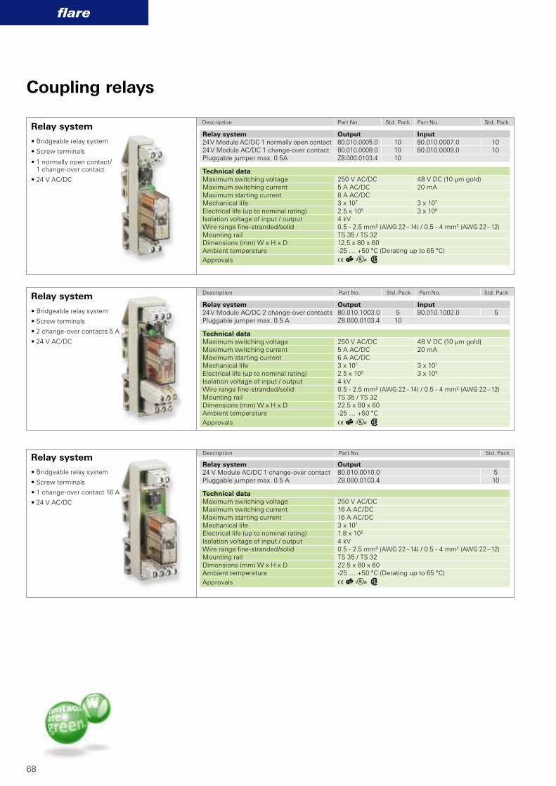
80.010.0005.0 10 80.010.0007.0 1080.010.0008.0 10 80.010.0009.0 10Z8.000.0103.4 10
AlE w
80.010.1003.0 5 80.010.1002.0 5Z8.000.0103.4 10
AlE w
80.010.0010.0 5Z8.000.0103.4 10
AlE w
flare
68
Coupling relays
• Bridgeable relay system
• Screw terminals
• 2 change-over contacts 5 A
• 24 V AC/DC
• Bridgeable relay system
• Screw terminals
• 1 change-over contact 16 A
• 24 V AC/DC
Relay system
Relay system
Relay systemRelay system Output Input
24 V Module AC/DC 1 normally open contact24 V Module AC/DC 1 change-over contactPluggable jumper max. 0.5A
Technical data
Maximum switching voltage 250 V AC/DC 48 V DC (10 µm gold)Maximum switching current 5 A AC/DC 20 mAMaximum starting current 8 A AC/DCMechanical life 3 x 10⁷ 3 x 10⁷
Electrical life (up to nominal rating) 2.5 x 10⁵ 3 x 10⁶
Isolation voltage of input / output 4 kVWire range fi ne-stranded/solid 0.5 - 2.5 mm² (AWG 22 – 14) / 0.5 - 4 mm2 (AWG 22 – 12)Mounting rail TS 35 / TS 32Dimensions (mm) W x H x D 12.5 x 80 x 60Ambient temperature -25 … +50 °C (Derating up to 65 °C)
Approvals
Relay system Output Input
24 V Module AC/DC 2 change-over contactsPluggable jumper max. 0.5 A
Technical data
Maximum switching voltage 250 V AC/DC 48 V DC (10 µm gold)Maximum switching current 5 A AC/DC 20 mAMaximum starting current 6 A AC/DCMechanical life 3 x 10⁷ 3 x 10⁷
Electrical life (up to nominal rating) 2.5 x 10⁵ 3 x 10⁶
Isolation voltage of input / output 4 kVWire range fi ne-stranded/solid 0.5 - 2.5 mm² (AWG 22 – 14) / 0.5 - 4 mm2 (AWG 22 – 12)Mounting rail TS 35 / TS 32Dimensions (mm) W x H x D 22.5 x 80 x 60Ambient temperature -25 … +50 °C
Approvals
Relay system Output
24 V Module AC/DC 1 change-over contactPluggable jumper max. 0.5 A
Technical data
Maximum switching voltage 250 V AC/DCMaximum switching current 16 A AC/DCMaximum starting current 16 A AC/DCMechanical life 3 x 10⁷
Electrical life (up to nominal rating) 1.8 x 10⁵
Isolation voltage of input / output 4 kVWire range fi ne-stranded/solid 0.5 - 2.5 mm² (AWG 22 – 14) / 0.5 - 4 mm2 (AWG 22 – 12)Mounting rail TS 35 / TS 32 Dimensions (mm) W x H x D 22.5 x 80 x 60Ambient temperature -25 … +50 °C (Derating up to 65 °C)
Approvals
Description Part No. Std. Pack Part No. Std. Pack
Description Part No. Std. Pack Part No. Std. Pack
Description Part No. Std. Pack
• Bridgeable relay system
• Screw terminals
• 1 normally open contact/1 change-over contact
• 24 V AC/DC
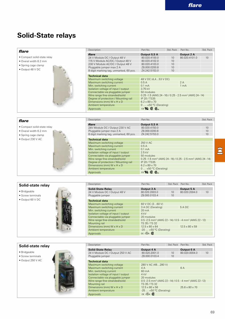
80.020.2001.0 10 80.020.0004.0 10Z8.000.0103.4 10
A E w
80.020.2003.0 10 80.020.2004.0 10Z8.000.0103.4 10
A E w
80.020.4150.0 10Z8.000.0200.8 10Z4.242.5153.0 10
Aq w h
80.020.4100.0 10 80.020.4101.0 1080.020.4102.0 1080.020.4103.0 10Z8.000.0200.8 10Z4.242.5153.0 10
Aq w h
flare
69
Solid-State relays
• Compact solid-state relay
• Overal width 6.2 mm
• Spring cage clamp
• Output 230 V AC
• Bridgeable
• Screw terminals
• Output 250 V AC
flare
flare
Solid-state relay
Solid-state relaySolid-State-Relay Output 4 A Output 6 A
24 V Module DC / Output 250 V ACPluggable jumper
Technical data
Maximum switching voltage 280 V AC (48…280 V)Maximum switching current 4 A 6 AMin. switching current 60 mAIsolation voltage of input / output 4 kVConnectable via pluggable jumper 20 modulesWire range fi ne-stranded/solid 0.5 -2.5 mm² (AWG 22 – 14) / 0.5 - 4 mm2 (AWG 22– 12)Mounting rail TS 35 / TS 32Dimensions (mm) W x H x D 12.5 x 80 x 56 25.6 x 80 x 70Ambient temperature -25 … +50 °C (Derating)
Approvals
Solid-State-Relay Output 3 A Output 5 A
24 V Module DC / Output 48 VPluggable jumper
Technical data
Maximum switching voltage 60 V DC (3…60 V)Maximum switching current 3 A DC (Derating) 5 A DCMin. switching current 20 mAIsolation voltage of input / output 4 kVConnectable via pluggable jumper 20 modulesWire range fi ne-stranded/solid 0.5 -2.5 mm² (AWG 22 – 14) / 0.5 - 4 mm2 (AWG 22 – 12)Mounting rail TS 35 / TS 32Dimensions (mm) W x H x D 12.5 x 80 x 64 12.5 x 80 x 59Ambient temperature -20 … +50 °C (Derating)
Approvals
flare Output 0,5 A
24V Module DC / Output 230 V ACPluggable jumper max 2 A8 digit marking tag, unmarked, 60 pcs.
Technical data
Maximum switching voltage 250 V ACMaximum switching current 0.5 AMin. switching current 0.1 mAIsolation voltage of input / output 2.5 kVConnectable via pluggable jumper 50 modulesWire range fi ne-stranded/solid 0.25 -1.5 mm² (AWG 24 – 16) / 0.25 - 2.5 mm2 (AWG 24 – 14)Degree of protection / Mounting rail IP 20 / TS35Dimensions (mm) W x H x D 6.2 x 89 x 70Ambient temperature 0 … +50 °C (Derating)
Approvals
flare Output 0,5 A Output 2 A
24 V Module DC / Output 48 V115 V Module AC/DC / Output 48 V230 V Module AC/DC / Output 48 VPluggable jumper max 2 A8 digit marking tag, unmarked, 60 pcs.
Technical data
Maximum switching voltage 48 V DC (4,4…53 V DC)Maximum switching current 0.5 A 2 AMin. switching current 0.1 mA 1 mAIsolation voltage of input / output 3.75 kVConnectable via pluggable jumper 50 modulesWire range fi ne-stranded/solid 0.25 -1.5 (AWG 24 – 16) / 0.25 - 2.5 mm2 (AWG 24 – 14)Degree of protection / Mounting rail IP 20 / TS35Dimensions (mm) W x H x D 6.2 x 89 x 70Ambient temperature 0 …. +50 °C (Derating)
Approvals
Description Part No. Std. Pack Part No. Std. Pack
Description Part No. Std. Pack
Description Part No. Std. Pack Part No. Std. Pack
Description Part No. Std. Pack Part No. Std. Pack
• Compact solid-state relay
• Overal width 6.2 mm
• Spring cage clamp
• Output 48 V DC
• Bridgeable
• Screw terminals
• Output 60 V DC

cores
70

cores
71
Analog isolation amplifi er of the
cores series
The cores series convinces with
fl exible use in process and industrial
automation.
They ensure a defi ned separation of
measurement and process signals
from the control system. And it
protects against voltage drops.
Analogue isolation amplifi ers also
convert signals into standardized
signal levels.
cores combines a highly precise
signal conversion with a very small
housing and fulfi ls actual demands
for such products.
Analog Isolation Amplifier
The Advantages:
• Digital conversion (up to 16 Bit)
• Highest accuracy (0.1 %) and
linearity
• Fastest reaction time (from 11 ms)
• 3 or 4 way galvanic isolation
• High isolation voltage
• Compact housing (also as thin
as 6.2 mm)
• Universal functions settable
• Wide temperature range
flexible
and precise

A E
A E
A E
cores C1 UI-B 82.003.0110.0
cores C1 PT-B 82.003.0120.0
cores C1 TC-B 82.003.0130.0
cores C1 UI-B
cores C1 PT-B
cores C1 TC-B
72
cores
Type Part No.
Type Part No.
Type Part No.
Analog Isolation Amplifier
Techncal data Input range (adjustable) 0/1 ... 5 V DC or 0/2 ... 10 V DC
0/4 ... 20 mA DC
Output range (adjustable) 0/1 ... 5 V DC or 0/2 ... 10 V DC0/4 ... 20 mA DC or 20 ... 4/0 mA DCactive or passive
Galvanic isolation yes, 3 way isolationIsolation voltage 1500 V ACAccuracy <0.1%, 14 Bit resolutionSupply voltage range 19.2 … 30 V DCPower consumption max. 500 mWConnection type Spring clamp
Wire range solid/fi ne-stranded 0.2 - 2.5 mm² (AWG 24 – 14)Degree of protection / Mounting rail IP 20 / TH 35 (EN60715) Dimensions (mm) W x H x D 6.2 x 93.1 x 102.5Temperature range -20 … +65 °C
Approvals (pending)
Technical data Input range (adjustable) PT100 with 2-, 3- or 4 wire connection
-150 … +650 °C
Output range (adjustable) 0/1 ... 5 V DC or 0 ... 10 V; 10 ... 0 V DC0/4 ... 20 mA DC or 20 ... 4/0 mA DC
Galvanic isolation yes, 3 way isolationIsolation voltage 1500 V ACAccuracy <0.1%, 14 Bit resolutionSupply voltage range 19.2 … 30 V DCPower consumption max. 500 mWConnection type Spring clamp
Wire range solid/fi ne-stranded 0.2 - 2.5 mm² (AWG 24 – 14)Degree of protection / Mounting rail IP 20 / TH 35 (EN60715) Dimensions (mm) W x H x D 6.2 x 93.1 x 102.5Temperature range -20 … +65 °C
Approvals (pending)
Technical data Input range (adjustable) Types of thermo coupler:
J, K, E, N, S, R, B, T
Output range (adjustable) 0/1 ... 5 V DC oder 0 ... 10 V DC0/4 ... 20 mA DC oder 20 ... 4/0 mA DC
Galvanic isolation yes, 3 way isolationIsolation voltage 1500 V ACAccuracy <0.1%, 14 Bit resolutionSupply voltage range 19.2 … 30 V DCPower consumption max. 500 mWConnection type Spring clamp
Wire range solid/fi ne-stranded 0.2 - 2.5 mm² (AWG 24 – 14)Degree of protection / Mounting rail IP 20 / TH 35 (EN60715) Dimensions (mm) W x H x D 6.2 x 93.1 x 102.5Temperature range -20 … +65 °C
Approvals (pending)
• Analog Isolation Amplifier
• 3 way isolation
• Input: voltage / current, output: voltage / current
• High accuracy by digital conversion
• Width 6.2 mm
• Spring clamp connection
• Wide temperature range
• Analog Isolation Amplifier
• 3 way isolation
• Input: PT 100, output: voltage / current
• High accuracy by digital conversion
• Width 6.2 mm
• Spring clamp connection
• Wide temperature range
• Analog Isolation Amplifier
• 3 way isolation
• Input: thermo coupler, output: voltage / current
• High accuracy by digital conversion
• Width 6.2 mm
• Spring clamp connection
• Wide temperature range
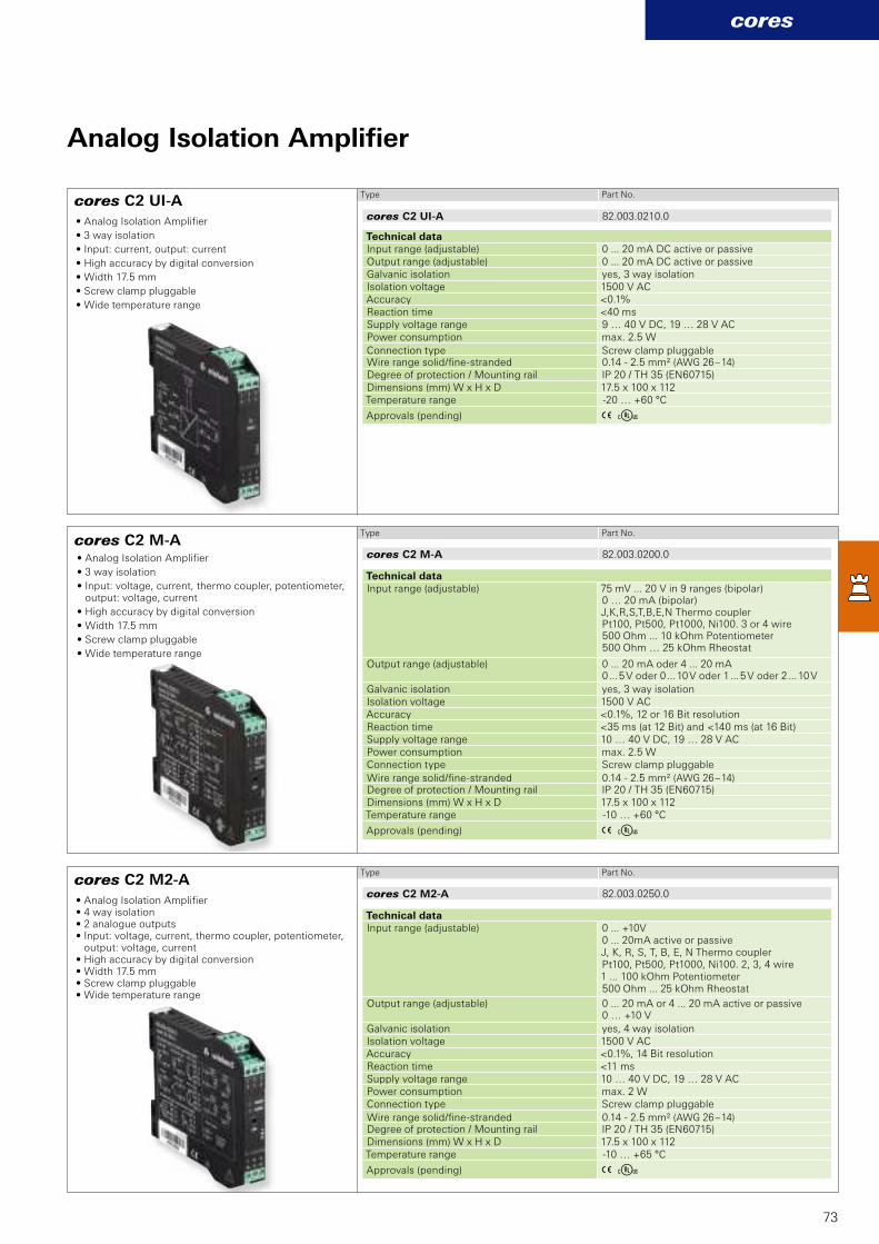
A E
A E
A E
cores C2 UI-A 82.003.0210.0
cores C2 M-A 82.003.0200.0
cores C2 M2-A 82.003.0250.0
cores C2 UI-A
cores C2 M-A
cores C2 M2-A
73
cores
Type Part No.
Type Part No.
Type Part No.
Analog Isolation Amplifier
Technical data Input range (adjustable) 0 ... 20 mA DC active or passiveOutput range (adjustable) 0 ... 20 mA DC active or passiveGalvanic isolation yes, 3 way isolationIsolation voltage 1500 V ACAccuracy <0.1%Reaction time <40 msSupply voltage range 9 … 40 V DC, 19 … 28 V ACPower consumption max. 2.5 W
Connection type Screw clamp pluggableWire range solid/fi ne-stranded 0.14 - 2.5 mm² (AWG 26 – 14)Degree of protection / Mounting rail IP 20 / TH 35 (EN60715) Dimensions (mm) W x H x D 17.5 x 100 x 112Temperature range -20 … +60 °C
Approvals (pending)
Technical data Input range (adjustable) 75 mV ... 20 V in 9 ranges (bipolar)
0 … 20 mA (bipolar) J,K,R,S,T,B,E,N Thermo coupler Pt100, Pt500, Pt1000, Ni100. 3 or 4 wire 500 Ohm ... 10 kOhm Potentiometer 500 Ohm … 25 kOhm Rheostat
Output range (adjustable) 0 ... 20 mA oder 4 ... 20 mA0 ... 5 V oder 0 ... 10 V oder 1 ... 5 V oder 2 ... 10 V
Galvanic isolation yes, 3 way isolationIsolation voltage 1500 V ACAccuracy <0.1%, 12 or 16 Bit resolutionReaction time <35 ms (at 12 Bit) and <140 ms (at 16 Bit)Supply voltage range 10 … 40 V DC, 19 … 28 V ACPower consumption max. 2.5 WConnection type Screw clamp pluggable
Wire range solid/fi ne-stranded 0.14 - 2.5 mm² (AWG 26 – 14)Degree of protection / Mounting rail IP 20 / TH 35 (EN60715) Dimensions (mm) W x H x D 17.5 x 100 x 112Temperature range -10 … +60 °C
Approvals (pending)
Technical data Input range (adjustable) 0 ... +10V
0 ... 20mA active or passiveJ, K, R, S, T, B, E, N Thermo couplerPt100, Pt500, Pt1000, Ni100. 2, 3, 4 wire1 ... 100 kOhm Potentiometer500 Ohm ... 25 kOhm Rheostat
Output range (adjustable) 0 ... 20 mA or 4 ... 20 mA active or passive0 … +10 V
Galvanic isolation yes, 4 way isolationIsolation voltage 1500 V ACAccuracy <0.1%, 14 Bit resolutionReaction time <11 msSupply voltage range 10 … 40 V DC, 19 … 28 V ACPower consumption max. 2 WConnection type Screw clamp pluggable
Wire range solid/fi ne-stranded 0.14 - 2.5 mm² (AWG 26 – 14)Degree of protection / Mounting rail IP 20 / TH 35 (EN60715) Dimensions (mm) W x H x D 17.5 x 100 x 112Temperature range -10 … +65 °C
Approvals (pending)
• Analog Isolation Amplifier
• 3 way isolation
• Input: current, output: current
• High accuracy by digital conversion
• Width 17.5 mm
• Screw clamp pluggable
• Wide temperature range
• Analog Isolation Amplifier
• 3 way isolation
• Input: voltage, current, thermo coupler, potentiometer, output: voltage, current
• High accuracy by digital conversion
• Width 17.5 mm
• Screw clamp pluggable
• Wide temperature range
• Analog Isolation Amplifier • 4 way isolation• 2 analogue outputs• Input: voltage, current, thermo coupler, potentiometer,
output: voltage, current• High accuracy by digital conversion• Width 17.5 mm• Screw clamp pluggable• Wide temperature range

74

flare TIME
75
The electronic relays are ideally
suited for standard, monitoring
and control tasks in order to
control function processes down
to the second. Depending on the
application, multiple-voltage and
multi-functional relays are available.
Decades of timer know-how are
packed into a completely new, highly
miniaturized generation of timers just
22.5 mm wide. Although the end of
the timer has been being predicted
for years now, as the PLC has spread,
high quality timers with well thought-
out designs and universal application
will continue to be needed in
industrial automation.
Always up to the minuteTimers
Timers remain crucial – in less
complex series machines, in later
modifi cations, everywhere where
other solutions would result in un-
necessary engineering and hardware
costs. For these applications Wieland
offers a range of timers that provides
everything you need. These devices
unite diverse features with an
effi ciency that permits the fullest
profi tability – from procurement and
warehousing through application and
operation, and fi nally to disposal.
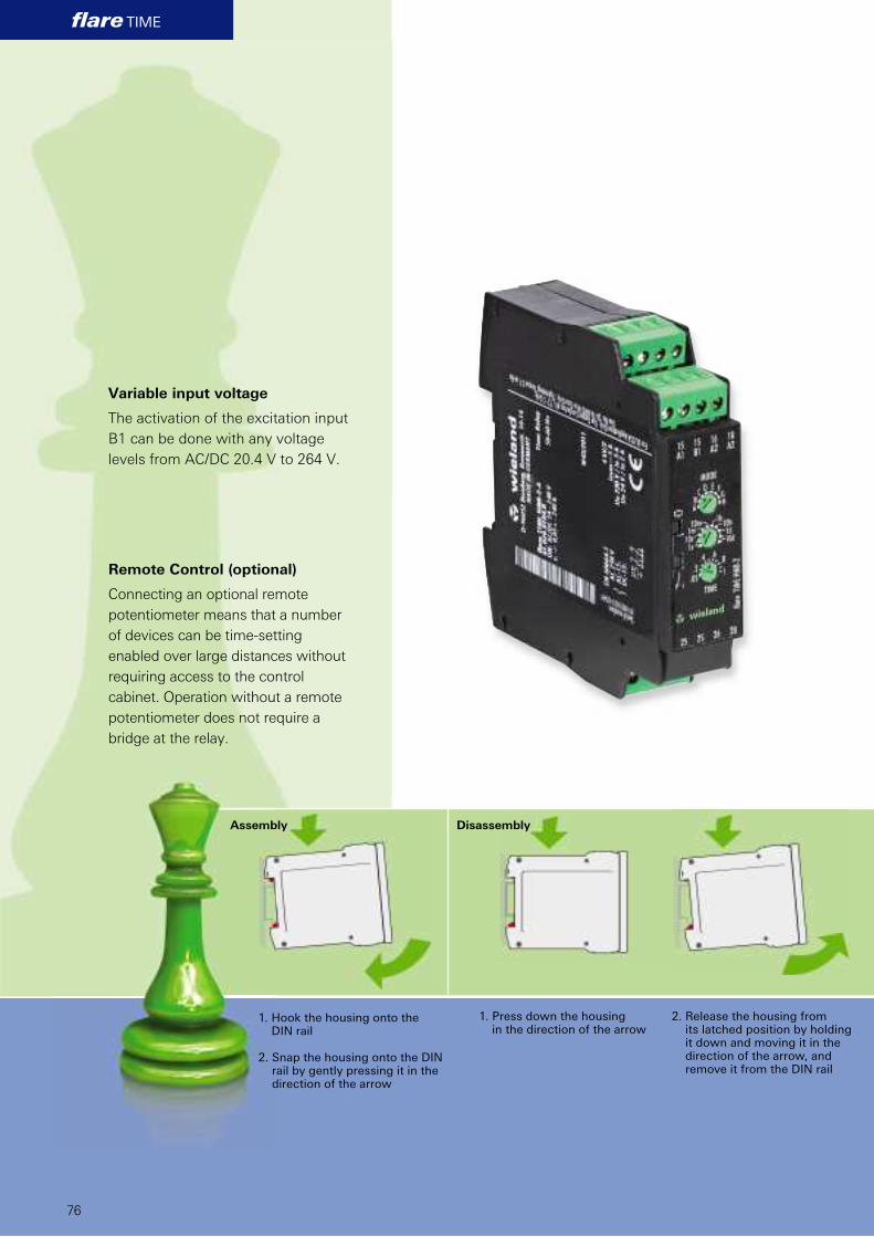
flare TIME
76
Variable input voltage
The activation of the excitation input
B1 can be done with any voltage
levels from AC/DC 20.4 V to 264 V.
Remote Control (optional)
Connecting an optional remote
potentiometer means that a number
of devices can be time-setting
enabled over large distances without
requiring access to the control
cabinet. Operation without a remote
potentiometer does not require a
bridge at the relay.
1. Hook the housing onto the DIN rail
2. Snap the housing onto the DIN rail by gently pressing it in the direction of the arrow
1. Press down the housing in the direction of the arrow
2. Release the housing from its latched position by holding it down and moving it in the direction of the arrow, and remove it from the DIN rail
Assembly Disassembly
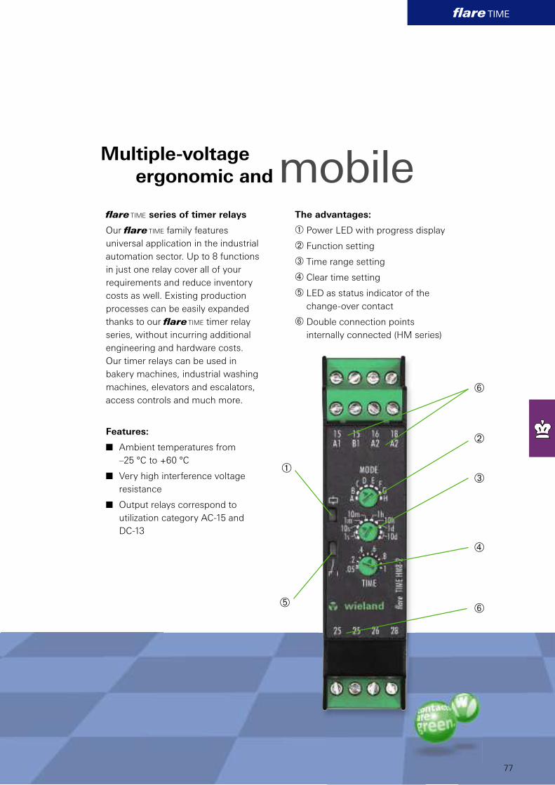
À
Á
Â
Ã
ÄÅ
Å
flare TIME
77
fl are TIME series of timer relays
Our fl are TIME family features
universal application in the industrial
automation sector. Up to 8 functions
in just one relay cover all of your
requirements and reduce inventory
costs as well. Existing production
processes can be easily expanded
thanks to our fl are TIME timer relay
series, without incurring additional
engineering and hardware costs.
Our timer relays can be used in
bakery machines, industrial washing
machines, elevators and escalators,
access controls and much more.
Features:
n Ambient temperatures from
–25 °C to +60 °C
n Very high interference voltage
resistance
n Output relays correspond to
utilization category AC-15 and
DC-13
Multiple-voltage
ergonomic and
The advantages:
À Power LED with progress display
Á Function setting
 Time range setting
à Clear time setting
Ä LED as status indicator of the
change-over contact
Å Double connection points
internally connected (HM series)
mobile
flare TIME
!
78
Electromechanical timer and switching
relays for DIN rails
Electromechanical timer and switching
relays for panel mounting
Further products and technical details can be found at
www.wieland-electric.com in our e-catalog.
Electronic timer and switching relays
for DIN rails
Electronic timer and switching relays
for panel mounting
flare TIME
fla
re T
IME
HM
8-2
-A
fla
re T
IME
HM
8-2
P-A
fla
re T
IME
HM
5-1
-A
fla
re T
IME
M8-2
fla
re T
IME
M8
-1
fla
re T
IME
M4
-2
fla
re T
IME
M4
-1
fla
re T
IME-S
81.0
20.0
10
4.0
81.0
20.0
13
4.0
81.0
20.0
10
0.0
81.0
20.0
00
3.0
81.0
20.0
00
2.0
81.0
20.0
001.0
81.0
20.0
00
0.0
81.0
20.4
10
0.0
• • • • • • •
• • • • • • • •
• • • • • • • •
• • • • •
• • • •
• • • • • • • •
• • • •
• • • • • •
• • • • • • • •
• • • • • • •
2 2 1 21) 1 21) 1 1
11) 11)
• • • • • • •
•
• • •
A A A A A A A
• • • • • • •
79
Electronic timer and switching relays for DIN rails Multifunction
1) = 1 timed and 1 instantaneous change-over contact or 2 timed change-over contacts, selectable
Description
Part no.
Model Multi-function
Multi-range
Function
Timer relays ON-delay
OFF-delay
ON-delay- and OFF-delay, symmetrical
Interval ON
relay
Interval ON
Interval OFF
Interval ON and Interval OFF
Repeat cycle
timer
OFF start, symmetrical and selectable
ON start, symmetrical and selectable
ON start, symmetrical and fi xed
OFF start and ON start, symmetrical and
fi xed, cycle time setting range
Star-delta relay Switch-over relay, Interval ON
Pulse relay Pulse relay, ON-delay, Pulse output
Pulse relay, OFF start, OFF start selectable,
ON time fi xed
Pulse relay, alternating, OFF or ON time
selectable
One shot (interval ON)
Contacts Timed change-over contact
Instantaneous change-over contact
Rated Voltage Multi-voltage AC/DC 24 to 230 (240) V
Special
Features
Remote potentiometer connection
Double connection points (internally connected) for trough cabling
Digital (D) or analog (A) settings
Housing Surface mounting 22.5 mm
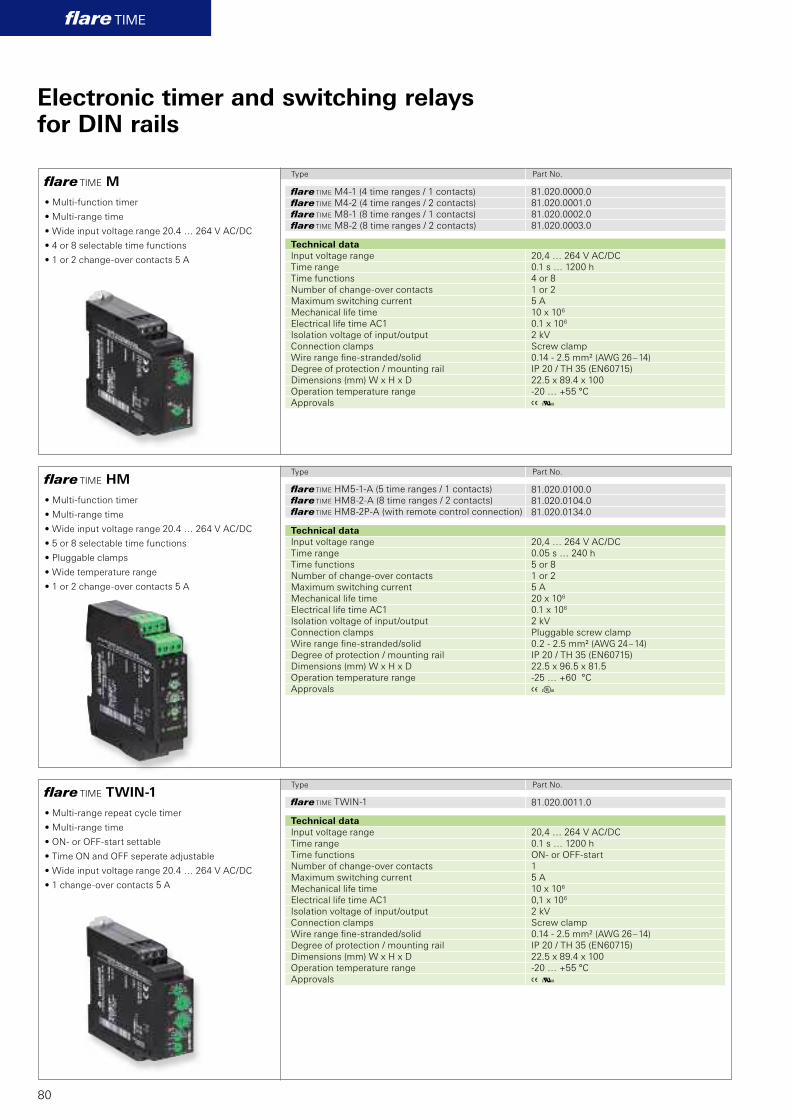
81.020.0000.0
81.020.0001.0
81.020.0002.0
81.020.0003.0
A K
81.020.0011.0
A K
81.020.0100.0
81.020.0104.0
81.020.0134.0
A E
flare TIME
flare TIME M
flare TIME TWIN-1
flare TIME HM
80
Electronic timer and switching relaysfor DIN rails
Type Part No.
Type Part No.
Type Part No.
• Multi-function timer
• Multi-range time
• Wide input voltage range 20.4 … 264 V AC/DC
• 4 or 8 selectable time functions
• 1 or 2 change-over contacts 5 A
• Multi-range repeat cycle timer
• Multi-range time
• ON- or OFF-start settable
• Time ON and OFF seperate adjustable
• Wide input voltage range 20.4 … 264 V AC/DC
• 1 change-over contacts 5 A
• Multi-function timer
• Multi-range time
• Wide input voltage range 20.4 … 264 V AC/DC
• 5 or 8 selectable time functions
• Pluggable clamps
• Wide temperature range
• 1 or 2 change-over contacts 5 A
fl are TIME M4-1 (4 time ranges / 1 contacts)
fl are TIME M4-2 (4 time ranges / 2 contacts)
fl are TIME M8-1 (8 time ranges / 1 contacts)
fl are TIME M8-2 (8 time ranges / 2 contacts)
Technical data
Input voltage range 20,4 … 264 V AC/DC
Time range 0.1 s … 1200 h
Time functions 4 or 8
Number of change-over contacts 1 or 2
Maximum switching current 5 A
Mechanical life time 10 x 106
Electrical life time AC1 0.1 x 10⁶
Isolation voltage of input/output 2 kV
Connection clamps Screw clamp
Wire range fi ne-stranded/solid 0.14 - 2.5 mm² (AWG 26 – 14)
Degree of protection / mounting rail IP 20 / TH 35 (EN60715)
Dimensions (mm) W x H x D 22.5 x 89.4 x 100
Operation temperature range -20 … +55 °C
Approvals
fl are TIME TWIN-1
Technical data
Input voltage range 20,4 … 264 V AC/DC
Time range 0.1 s … 1200 h
Time functions ON- or OFF-start
Number of change-over contacts 1
Maximum switching current 5 A
Mechanical life time 10 x 106
Electrical life time AC1 0,1 x 10⁶
Isolation voltage of input/output 2 kV
Connection clamps Screw clamp
Wire range fi ne-stranded/solid 0.14 - 2.5 mm² (AWG 26 – 14)
Degree of protection / mounting rail IP 20 / TH 35 (EN60715)
Dimensions (mm) W x H x D 22.5 x 89.4 x 100
Operation temperature range -20 … +55 °C
Approvals
fl are TIME HM5-1-A (5 time ranges / 1 contacts)
fl are TIME HM8-2-A (8 time ranges / 2 contacts)
fl are TIME HM8-2P-A (with remote control connection)
Technical data
Input voltage range 20,4 … 264 V AC/DC
Time range 0.05 s … 240 h
Time functions 5 or 8
Number of change-over contacts 1 or 2
Maximum switching current 5 A
Mechanical life time 20 x 106
Electrical life time AC1 0.1 x 10⁶
Isolation voltage of input/output 2 kV
Connection clamps Pluggable screw clamp
Wire range fi ne-stranded/solid 0.2 - 2.5 mm² (AWG 24 – 14)
Degree of protection / mounting rail IP 20 / TH 35 (EN60715)
Dimensions (mm) W x H x D 22.5 x 96.5 x 81.5
Operation temperature range -25 … +60 °C
Approvals

81.020.0010.0
A K
81.020.4100.0
wh
81.020.4101.0
81.020.4102.0
wh
flare TIME
flare TIME OFF-1
flare TIMER-S
flare TIMER-A
81
Electronic timer and switching relaysfor DIN rails
Type Part No.
Type Part No.
Type Part No.
• OFF delayed timer
• No auxiliary voltage necessary
• 2 time ranges setable
• 1 change-over contacts 5 A
• Multi-function timer
• ON-delay and OFF-delay
• One shot and flashing
• Spring clamp
• Width 6.2 mm
• 1 change-over contacts 6 A
• Timer
• ON-delay
• Spring clamp
• Width 6.2 mm
• 1 change-over contacts 6 A
fl are TIME OFF-1
Technical data
Input voltage range 170 … 264 V AC
Time range 1 … 120 s
Time functions OFF delay
Number of change-over contacts 1
Maximum switching current 5 A
Mechanical life time 10 x 106
Electrical life time AC1 0.1 x 10⁶
Isolation voltage of input/output 2 kV
Connection clamps Screw clamp
Wire range fi ne-stranded/solid 0.14 - 2.5 mm² (AWG 26 – 14)
Degree of protection / Mounting rail IP 20 / TH 35 (EN60715)
Dimensions (mm) W x H x D 22.5 x 89.4 x 100
Operation temperature range -20 … +55 °C
Approvals
fl are TIMER-S-250250V6A
Technical data
Input voltage range 24 V DC +25%/-20%
Time range 0.1 … 300 s
Number of change-over contacts 1
Maximum switching current 6 A
Mechanical life time 2 x 10⁷
Electrical life time at 24 V DC / 2 A 0.6 x 10⁶
Electrical life time at 230 V AC / 6 A 0.8 x 10⁵
Isolation voltage of input/output 4 kV
Connection clamps Spring clamp
Wire range fi ne-stranded/solid 0.25 - 1.5 mm² (AWG 24-16) /
0.25 - 2.5 mm² (AWG 24-14)
Degree of protection / Mounting rail IP 20 / TH 35 (EN60715)
Dimensions (mm) W x H x D 6,2 x 89 x 70mm
Operation temperature range 0 … +50 °C
Approvals
fl are TIMER-A/0100-S-250V6A
fl are TIMER-A/0060-S-250V6A
Technical data
Input voltage range 24 V DC +25%/-20%
Time range TIMER A/0100 1 … 100 s
Time range TIMER A/0060 1 … 100 min
Number of change-over contacts 1
Maximum switching current 6 A
Mechanical life time 2 x 10⁷
Electrical life time at 24 V DC / 2 A 0.6 x 10⁶
Electrical life time at 230 V AC / 6 A 0.8 x 10⁵
Isolation voltage of input/output 4 kV
Connection clamps Spring clamp
Wire range fi ne-stranded/solid 0.25 - 1.5 mm² (AWG 24-16) /
0.25 - 2.5 mm² (AWG 24-14)
Degree of protection / Mounting rail IP 20 / TH 35 (EN60715)
Dimensions (mm) W x H x D 6,2 x 89 x 70mm
Operation temperature range 0 … +50 °C
Approvals
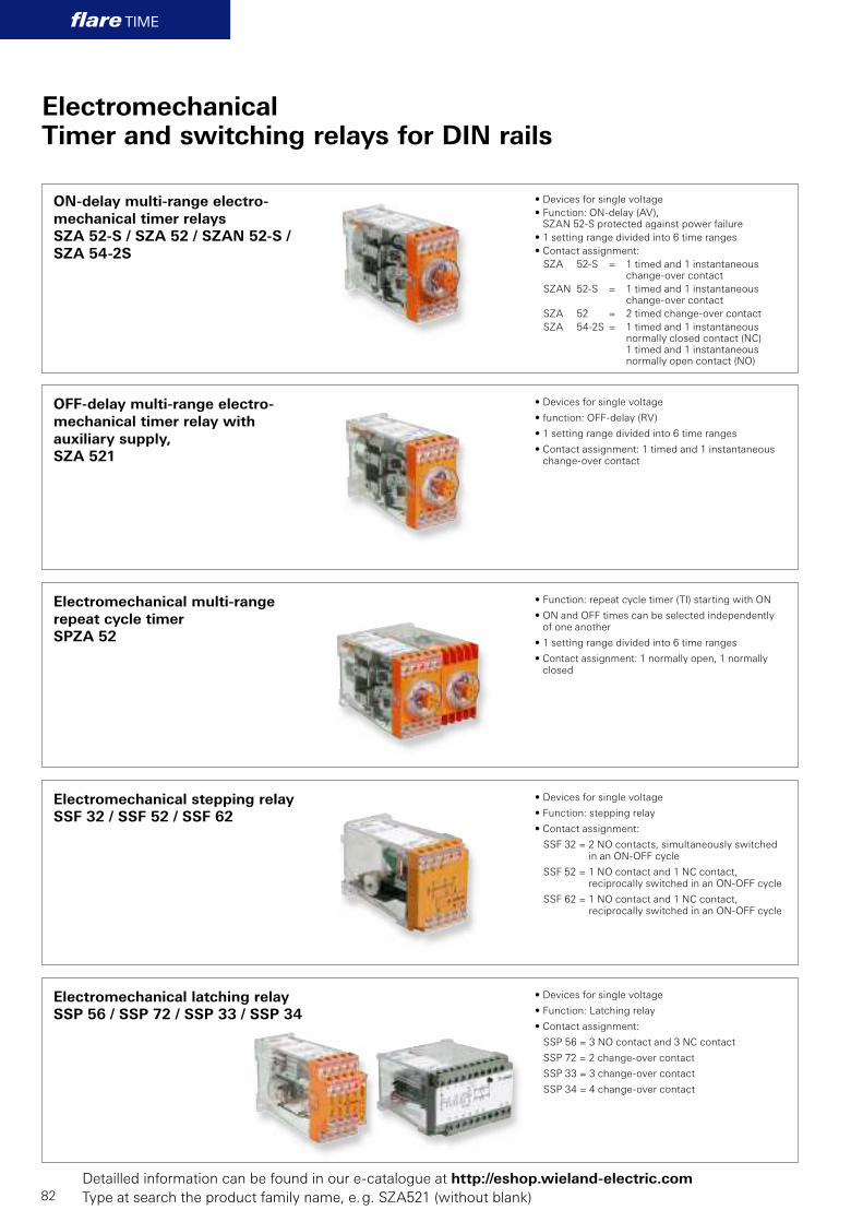
flare TIME
82
Electromechanical Timer and switching relays for DIN rails
Electromechanical multi-range
repeat cycle timer
SPZA 52
Electromechanical latching relay
SSP 56 / SSP 72 / SSP 33 / SSP 34
Electromechanical stepping relay
SSF 32 / SSF 52 / SSF 62
• Function: repeat cycle timer (TI) starting with ON
• ON and OFF times can be selected independently of one another
• 1 setting range divided into 6 time ranges
• Contact assignment: 1 normally open, 1 normally closed
• Devices for single voltage
• Function: stepping relay
• Contact assignment:
SSF 32 = 2 NO contacts, simultaneously switched in an ON-OFF cycle
SSF 52 = 1 NO contact and 1 NC contact, reciprocally switched in an ON-OFF cycle
SSF 62 = 1 NO contact and 1 NC contact,reciprocally switched in an ON-OFF cycle
ON-delay multi-range electro-
mechanical timer relays
SZA 52-S / SZA 52 / SZAN 52-S /
SZA 54-2S
• Devices for single voltage
• Function: ON-delay (AV), SZAN 52-S protected against power failure
• 1 setting range divided into 6 time ranges
• Contact assignment:
SZA 52-S = 1 timed and 1 instantaneous change-over contact
SZAN 52-S = 1 timed and 1 instantaneous change-over contact
SZA 52 = 2 timed change-over contact
SZA 54-2S = 1 timed and 1 instantaneous normally closed contact (NC)1 timed and 1 instantaneous normally open contact (NO)
• Devices for single voltage
• function: OFF-delay (RV)
• 1 setting range divided into 6 time ranges
• Contact assignment: 1 timed and 1 instantaneous change-over contact
• Devices for single voltage
• Function: Latching relay
• Contact assignment:
SSP 56 = 3 NO contact and 3 NC contact
SSP 72 = 2 change-over contact
SSP 33 = 3 change-over contact
SSP 34 = 4 change-over contact
OFF-delay multi-range electro-
mechanical timer relay with
auxiliary supply,
SZA 521
Detailled information can be found in our e-catalogue at http://eshop.wieland-electric.com
Type at search the product family name, e. g. SZA521 (without blank)
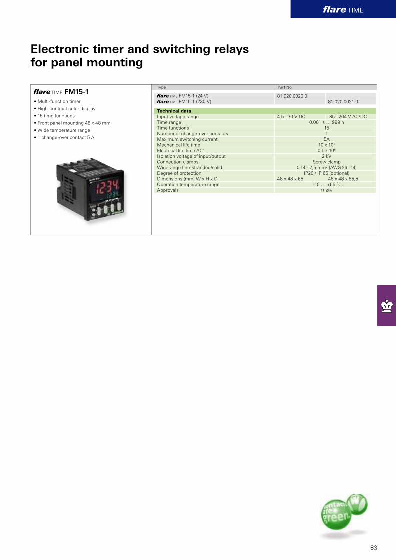
81.020.0020.0
81.020.0021.0
A E
flare TIME
flare TIME FM15-1
83
Electronic timer and switching relaysfor panel mounting
Type Part No.
• Multi-function timer
• High-contrast color display
• 15 time functions
• Front panel mounting 48 x 48 mm
• Wide temperature range
• 1 change-over contact 5 A
fl are TIME FM15-1 (24 V)
fl are TIME FM15-1 (230 V)
Technical data
Input voltage range 4.5...30 V DC 85...264 V AC/DC
Time range 0.001 s … 999 h
Time functions 15
Number of change-over contacts 1
Maximum switching current 5A
Mechanical life time 10 x 106
Electrical life time AC1 0.1 x 10⁶
Isolation voltage of input/output 2 kV
Connection clamps Screw clamp
Wire range fi ne-stranded/solid 0.14 - 2,5 mm² (AWG 26 – 14)
Degree of protection IP20 / IP 66 (optional)
Dimensions (mm) W x H x D 48 x 48 x 65 48 x 48 x 85,5
Operation temperature range -10 … +55 °C
Approvals
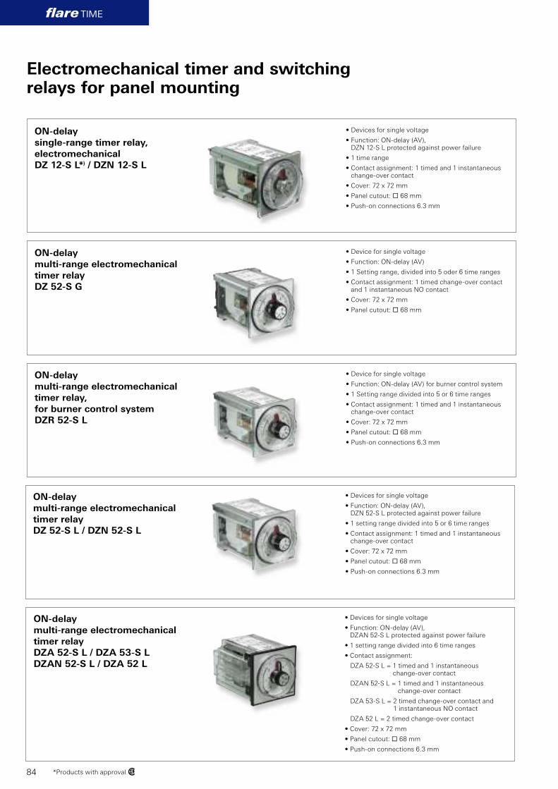
flare TIME
84
Electromechanical timer and switchingrelays for panel mounting
ON-delay
single-range timer relay,
electromechanical
DZ 12-S L*) / DZN 12-S L
• Devices for single voltage
• Function: ON-delay (AV), DZN 12-S L protected against power failure
• 1 time range
• Contact assignment: 1 timed and 1 instantaneous change-over contact
• Cover: 72 x 72 mm
• Panel cutout: ¨ 68 mm
• Push-on connections 6.3 mm
ON-delay
multi-range electromechanical
timer relay,
for burner control system
DZR 52-S L
*Products with approval w
ON-delay
multi-range electromechanical
timer relay
DZ 52-S G
• Device for single voltage
• Function: ON-delay (AV)
• 1 Setting range, divided into 5 oder 6 time ranges
• Contact assignment: 1 timed change-over contact and 1 instantaneous NO contact
• Cover: 72 x 72 mm
• Panel cutout: ¨ 68 mm
• Device for single voltage
• Function: ON-delay (AV) for burner control system
• 1 Setting range divided into 5 or 6 time ranges
• Contact assignment: 1 timed and 1 instantaneous change-over contact
• Cover: 72 x 72 mm
• Panel cutout: ¨ 68 mm
• Push-on connections 6.3 mm
ON-delay
multi-range electromechanical
timer relay
DZA 52-S L / DZA 53-S L
DZAN 52-S L / DZA 52 L
ON-delay
multi-range electromechanical
timer relay
DZ 52-S L / DZN 52-S L
• Devices for single voltage
• Function: ON-delay (AV), DZN 52-S L protected against power failure
• 1 setting range divided into 5 or 6 time ranges
• Contact assignment: 1 timed and 1 instantaneous change-over contact
• Cover: 72 x 72 mm
• Panel cutout: ¨ 68 mm
• Push-on connections 6.3 mm
• Devices for single voltage
• Function: ON-delay (AV), DZAN 52-S L protected against power failure
• 1 setting range divided into 6 time ranges
• Contact assignment:
DZA 52-S L = 1 timed and 1 instantaneous change-over contact
DZAN 52-S L = 1 timed and 1 instantaneous change-over contact
DZA 53-S L = 2 timed change-over contact and 1 instantaneous NO contact
DZA 52 L = 2 timed change-over contact
• Cover: 72 x 72 mm
• Panel cutout: ¨ 68 mm
• Push-on connections 6.3 mm

flare TIME
85
Electromechanical timer and switchingrelays for panel mounting
ON-delay
multi-range electromechanical
timer relay
DZ 74-2S L
ON-delay
multi-range electromechanical
timer relay
DZ 72-S / DZ 74-2S
• Devices for single voltage
• Function: ON-delay (AV)
• 1 setting range divided into 6 time ranges
• Contact assignment: 1 timed NC contact, 1 instantaneous and 1 timed NO contact
• without time accumulation
• Cover: 96 x 96 mm
• Panel cutout: ¨ 91 mm
• Push-on connections 6.3 mm
• Devices for single voltage
• Function: ON-delay (AV)
• 1 setting range divided into 5 or 6 time ranges
• Contact assignment:
DZ 72-S = 1 timed and 1 instantaneous change-over contact
DZ 74-2S = 1 instantaneous and 1 timed NC contact, 1 instantaneous and 1 timed NO contact
• Cover: 96 x 96 mm
• Panel cutout: ¨ 91 mm
ON-delay
single-range electromechanical
timer relay,
for burner control system
DZR 12-S L
• Devices for single voltage
• Function: ON-delay (AV) for burner control system
• 1 time range
• Contact assignment: 1 timed and 1 instantaneous change-over contact
• Cover: 72 x 72 mm
• Panel cutout: ¨ 68 mm
• Push-on connections 6.3 mm
OFF-delay
multi-range electromechanical
timer relay
DZ 521 L
OFF-delay
multi-range electromechanical
timer relay
DZA 521 L
• Devices for single voltage
• Function: OFF-delay (RV)
• 1 setting range divided into 5 or 6 time ranges
• Contact assignment: 1 timed and 1 instantaneous change-over contact
• Cover: 72 x 72 mm
• Panel cutout: ¨ 68 mm
• Push-on connections 6.3 mm
• Devices for single voltage
• Function: OFF-delay (RV)
• 1 setting range divided into 6 time ranges
• Contact assignment: 1 timed and 1 instantaneous change-over contact
• Cover: 72 x 72 mm
• Panel cutout: ¨ 68 mm
• Push-on connections 6.3 mm
• New housing concept
Detailled information can be found in our e-catalogue at http://eshop.wieland-electric.com
Type at search the product family name,. e. g. DZ12 (without blank)

86
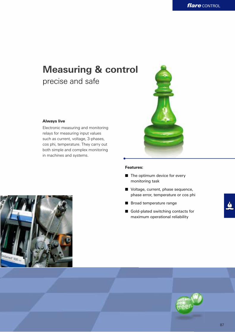
flare CONTROL
87
Always live
Electronic measuring and monitoring
relays for measuring input values
such as current, voltage, 3-phases,
cos phi, temperature. They carry out
both simple and complex monitoring
in machines and systems.
Measuring & controlprecise and safe
Features:
n The optimum device for every
monitoring task
n Voltage, current, phase sequence,
phase error, temperature or cos phi
n Broad temperature range
n Gold-plated switching contacts for
maximum operational reliability
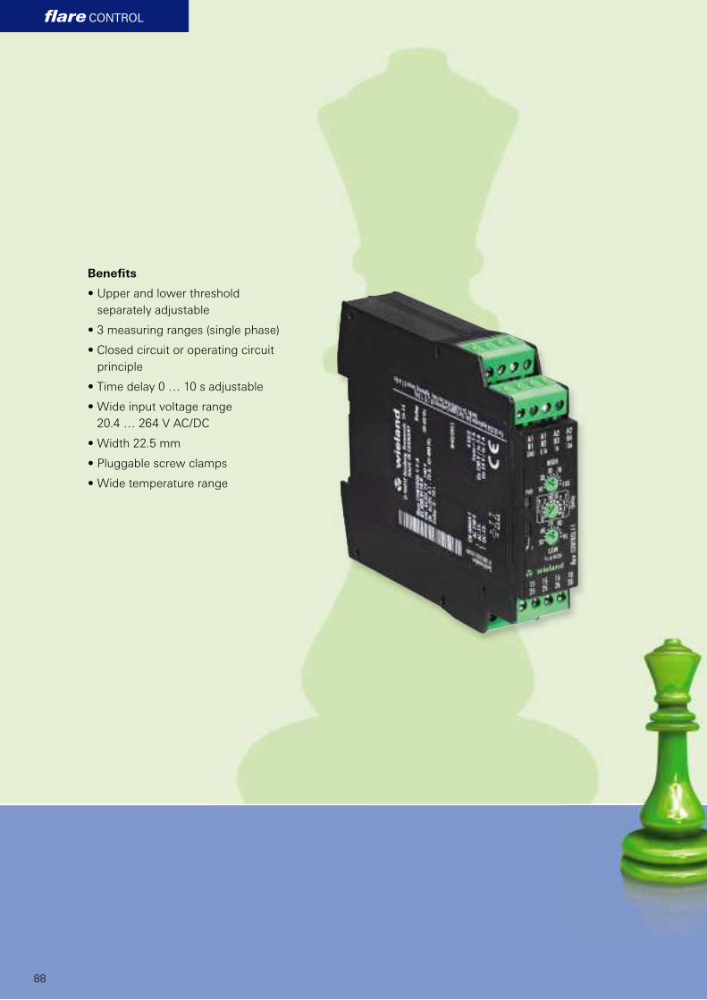
flare CONTROL
88
Benefi ts
• Upper and lower threshold
separately adjustable
• 3 measuring ranges (single phase)
• Closed circuit or operating circuit
principle
• Time delay 0 … 10 s adjustable
• Wide input voltage range
20.4 … 264 V AC/DC
• Width 22.5 mm
• Pluggable screw clamps
• Wide temperature range
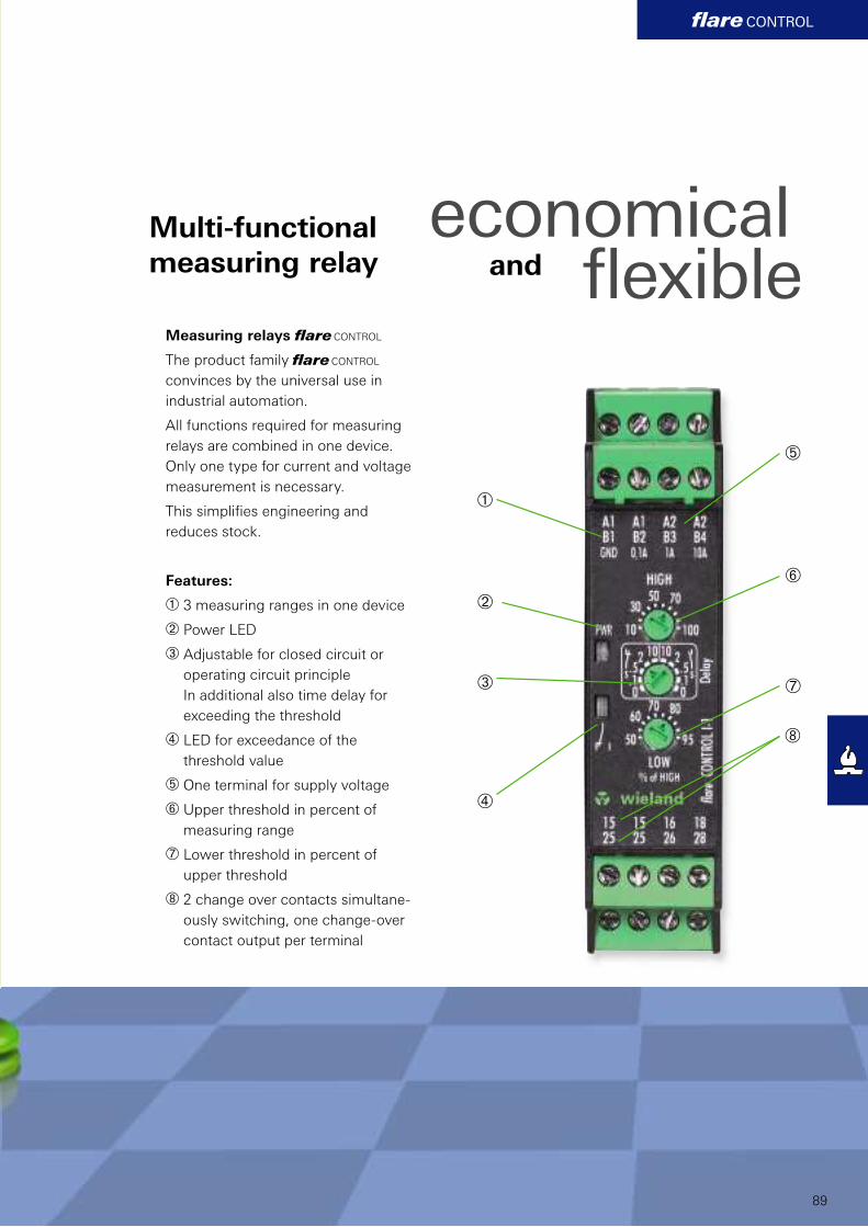
À
Á
Â
Ã
Ä
Å
Æ
Ç
flare CONTROL
89
Multi-functional
measuring relay
economical
and flexibleMeasuring relays fl are CONTROL
The product family fl are CONTROL
convinces by the universal use in
industrial automation.
All functions required for measuring
relays are combined in one device.
Only one type for current and voltage
measurement is necessary.
This simplifi es engineering and
reduces stock.
Features:
À 3 measuring ranges in one device
Á Power LED
 Adjustable for closed circuit or
operating circuit principle
In additional also time delay for
exceeding the threshold
à LED for exceedance of the
threshold value
Ä One terminal for supply voltage
Å Upper threshold in percent of
measuring range
Æ Lower threshold in percent of
upper threshold
Ç 2 change over contacts simultane-
ously switching, one change-over
contact output per terminal
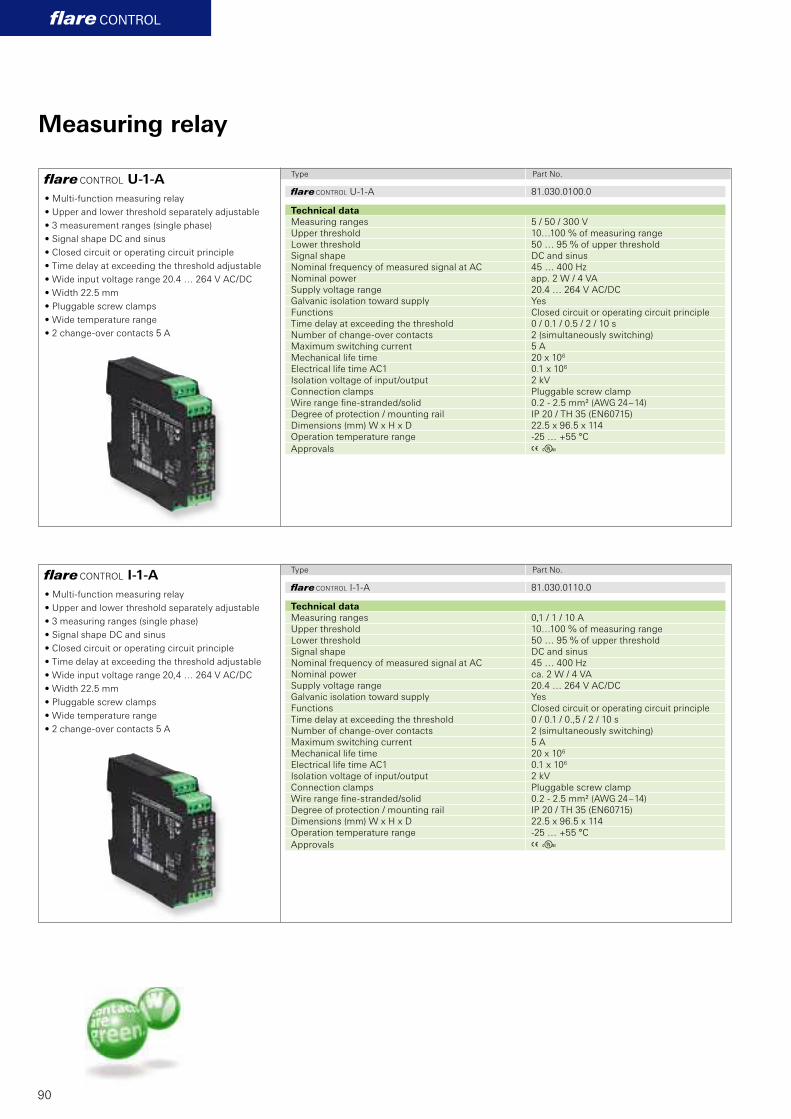
81.030.0100.0
A E
81.030.0110.0
A E
flare CONTROL U-1-A
flare CONTROL I-1-A
flare CONTROL
90
Measuring relay
Type Part No.
Type Part No.
• Multi-function measuring relay
• Upper and lower threshold separately adjustable
• 3 measurement ranges (single phase)
• Signal shape DC and sinus
• Closed circuit or operating circuit principle
• Time delay at exceeding the threshold adjustable
• Wide input voltage range 20.4 … 264 V AC/DC
• Width 22.5 mm
• Pluggable screw clamps
• Wide temperature range
• 2 change-over contacts 5 A
• Multi-function measuring relay
• Upper and lower threshold separately adjustable
• 3 measuring ranges (single phase)
• Signal shape DC and sinus
• Closed circuit or operating circuit principle
• Time delay at exceeding the threshold adjustable
• Wide input voltage range 20,4 … 264 V AC/DC
• Width 22.5 mm
• Pluggable screw clamps
• Wide temperature range
• 2 change-over contacts 5 A
fl are CONTROL U-1-A
Technical data
Measuring ranges 5 / 50 / 300 V
Upper threshold 10…100 % of measuring range
Lower threshold 50 … 95 % of upper threshold
Signal shape DC and sinus
Nominal frequency of measured signal at AC 45 … 400 Hz
Nominal power app. 2 W / 4 VA
Supply voltage range 20.4 … 264 V AC/DC
Galvanic isolation toward supply Yes
Functions Closed circuit or operating circuit principle
Time delay at exceeding the threshold 0 / 0.1 / 0.5 / 2 / 10 s
Number of change-over contacts 2 (simultaneously switching)
Maximum switching current 5 A
Mechanical life time 20 x 106
Electrical life time AC1 0.1 x 10⁶
Isolation voltage of input/output 2 kV
Connection clamps Pluggable screw clamp
Wire range fi ne-stranded/solid 0.2 - 2.5 mm² (AWG 24 – 14)
Degree of protection / mounting rail IP 20 / TH 35 (EN60715)
Dimensions (mm) W x H x D 22.5 x 96.5 x 114
Operation temperature range -25 … +55 °C
Approvals
fl are CONTROL I-1-A
Technical data
Measuring ranges 0,1 / 1 / 10 A
Upper threshold 10…100 % of measuring range
Lower threshold 50 … 95 % of upper threshold
Signal shape DC and sinus
Nominal frequency of measured signal at AC 45 … 400 Hz
Nominal power ca. 2 W / 4 VA
Supply voltage range 20.4 … 264 V AC/DC
Galvanic isolation toward supply Yes
Functions Closed circuit or operating circuit principle
Time delay at exceeding the threshold 0 / 0.1 / 0.,5 / 2 / 10 s
Number of change-over contacts 2 (simultaneously switching)
Maximum switching current 5 A
Mechanical life time 20 x 106
Electrical life time AC1 0.1 x 10⁶
Isolation voltage of input/output 2 kV
Connection clamps Pluggable screw clamp
Wire range fi ne-stranded/solid 0.2 - 2.5 mm² (AWG 24 – 14)
Degree of protection / mounting rail IP 20 / TH 35 (EN60715)
Dimensions (mm) W x H x D 22.5 x 96.5 x 114
Operation temperature range -25 … +55 °C
Approvals
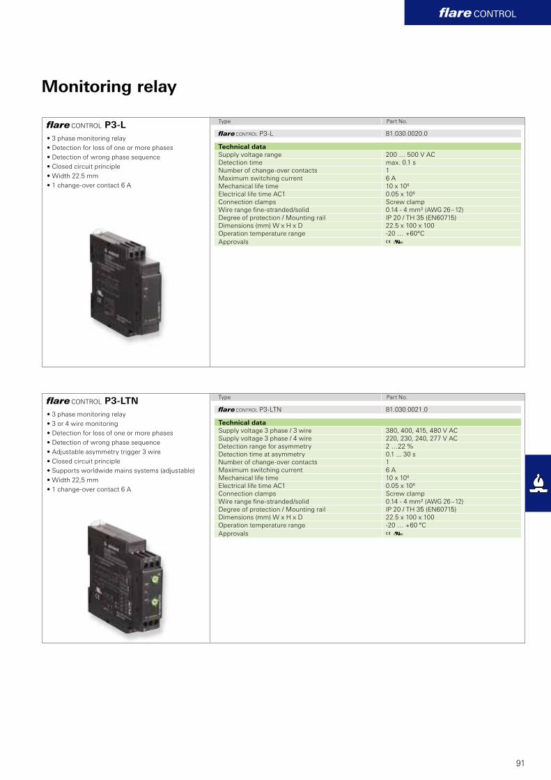
81.030.0020.0
A K
81.030.0021.0
A K
flare CONTROL P3-L
flare CONTROL P3-LTN
flare CONTROL
91
Monitoring relay
Type Part No.
Type Part No.
• 3 phase monitoring relay
• Detection for loss of one or more phases
• Detection of wrong phase sequence
• Closed circuit principle
• Width 22.5 mm
• 1 change-over contact 6 A
• 3 phase monitoring relay
• 3 or 4 wire monitoring
• Detection for loss of one or more phases
• Detection of wrong phase sequence
• Adjustable asymmetry trigger 3 wire
• Closed circuit principle
• Supports worldwide mains systems (adjustable)
• Width 22,5 mm
• 1 change-over contact 6 A
fl are CONTROL P3-L
Technical data
Supply voltage range 200 … 500 V AC
Detection time max. 0.1 s
Number of change-over contacts 1
Maximum switching current 6 A
Mechanical life time 10 x 106
Electrical life time AC1 0.05 x 10⁶
Connection clamps Screw clamp
Wire range fi ne-stranded/solid 0.14 - 4 mm² (AWG 26 – 12)
Degree of protection / Mounting rail IP 20 / TH 35 (EN60715)
Dimensions (mm) W x H x D 22.5 x 100 x 100
Operation temperature range -20 … +60°C
Approvals
fl are CONTROL P3-LTN
Technical data
Supply voltage 3 phase / 3 wire 380, 400, 415, 480 V AC
Supply voltage 3 phase / 4 wire 220, 230, 240, 277 V AC
Detection range for asymmetry 2 …22 %
Detection time at asymmetry 0.1 ... 30 s
Number of change-over contacts 1
Maximum switching current 6 A
Mechanical life time 10 x 106
Electrical life time AC1 0.05 x 10⁶
Connection clamps Screw clamp
Wire range fi ne-stranded/solid 0.14 - 4 mm² (AWG 26 – 12)
Degree of protection / Mounting rail IP 20 / TH 35 (EN60715)
Dimensions (mm) W x H x D 22.5 x 100 x 100
Operation temperature range -20 … +60 °C
Approvals

92

93
Contacts are green
Wieland Electric is one of the global
technology and innovation leaders in
the fi eld of pluggable connections for
building system technology and in-
dustrial automation. Wherever power
and signals are distributed, Wieland's
motto is: green light for innovative
ideas. Because: contacts are green.
Wieland Electric offers you suitable
products for all applications.
More products which complement yourinterface applications
Wieland product ranges:
n Safety
n DIN rail terminal blocks
n Industrial plug connectors
n Fieldbus components
n Distributed automation
n Circular connector system
n System plug connectors
n PCB terminals and connectors
contacts are green
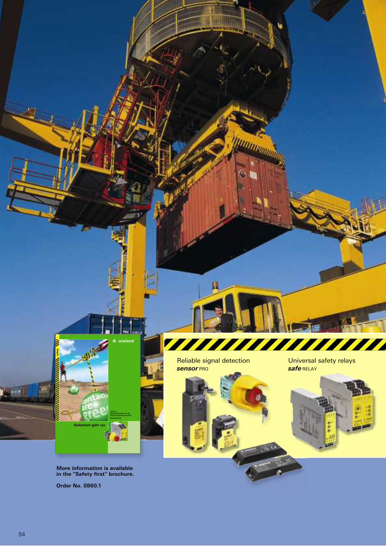
94
safety
safety
Sichere
Systemlösungen für die
Automatisierungstechnik
Katalog 2012
Sicherheit geht vor.
More information is available in the "Safety first" brochure.
Order No. 0860.1
Universal safety relays
safe RELAY
Reliable signal detection
sensor PRO

95
Modular safety units
samos®Compact safety
control samos®PRO
The demands on facilities, machines
and vehicles are high these days.
Apart from the productivity and
effi ciency of a machine or vehicle,
the focus is also increasingly on
safety. Designing modern means
of transportation, facilities and
machines also requires consideration
of the safety of the persons working
with these machines or using these
means of transportation.
Reliable and innovative solutions are
needed that contribute to meeting
this important requirement without
affecting the productivity and
availability of the facility or means of
transportation. With its sensor PRO,
safe RELAY, samos® and samos®PRO,
Wieland Electric offers superior
quality safety components which can
contribute substantially to safety in
production and operation of modern
facilities or machines.
Safety is a matter of
confidence
safety
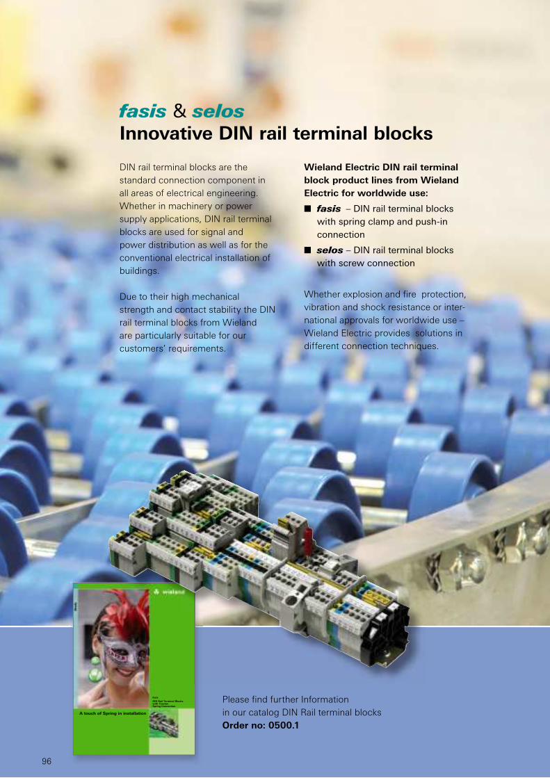
96
fasis & selos
Innovative DIN rail terminal blocks
Wieland Electric DIN rail terminal
block product lines from Wieland
Electric for worldwide use:
n fasis – DIN rail terminal blocks
with spring clamp and push-in
connection
n selos – DIN rail terminal blocks
with screw connection
Whether explosion and fi re protection,
vibration and shock resistance or inter-
national approvals for worldwide use –
Wieland Electric provides solutions in
different connection techniques.
DIN rail terminal blocks are the
standard connection component in
all areas of electrical engineering.
Whether in machinery or power
supply applications, DIN rail terminal
blocks are used for signal and
power distribution as well as for the
conventional electrical installation of
buildings.
Due to their high mechanical
strength and contact stability the DIN
rail terminal blocks from Wieland
are particularly suitable for our
customers’ requirements.
Please fi nd further Information
in our catalog DIN Rail terminal blocks
Order no: 0500.1
A touch of Spring in installation
fasis
DIN Rail Terminal Blockswith TensionSpring Connection
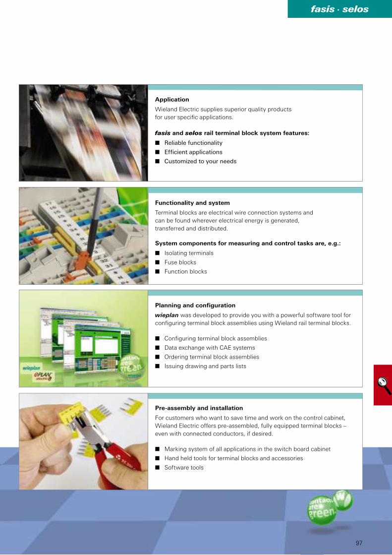
97
fasis . selos
Application
Wieland Electric supplies superior quality products
for user specifi c applications.
fasis and selos rail terminal block system features:
n Reliable functionality
n Efficient applications
n Customized to your needs
Functionality and system
Terminal blocks are electrical wire connection systems and
can be found wherever electrical energy is generated,
transferred and distributed.
System components for measuring and control tasks are, e.g.:
n Isolating terminals
n Fuse blocks
n Function blocks
Planning and configuration
wieplan was developed to provide you with a powerful software tool for
confi guring terminal block assemblies using Wieland rail terminal blocks.
n Configuring terminal block assemblies
n Data exchange with CAE systems
n Ordering terminal block assemblies
n Issuing drawing and parts lists
Pre-assembly and installation
For customers who want to save time and work on the control cabinet,
Wieland Electric offers pre-assembled, fully equipped terminal blocks –
even with connected conductors, if desired.
n Marking system of all applications in the switch board cabinet
n Hand held tools for terminal blocks and accessories
n Software tools

98

99
revos
The revos heavy-duty industrial
connectors are categorized according
to their housings, contact inserts and
connection technology. A wide range
standard program, as well as modular
components that can be combined,
per customer specifi c requirements,
are available.
For any application –
Heavy-duty industrial connectors
n revos BASIC with 6 to 92-pole
contact inserts
n revos POWER high-current plugg-
able connector for currents
up to 100 A
n revos HD high density multipole
pluggable connector with up to
64 poles and up to 10 A
n revos FLEX modular hybrid
pluggable connector system to
equip your connector, as needed,
with mixed contact inserts,
including signal, pneumatics and
fiber optic cable components
n revos BASIC EMV for applications
where electromagnetic inter-
ferences must be shielded from
entering or exiting the connector.
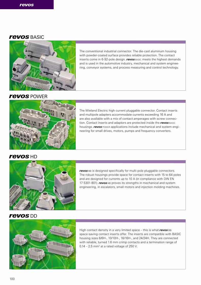
100
revos
revos BASIC
revos HD
revos POWER
revos DD
The conventional industrial connector. The die-cast aluminum housing
with powder-coated surface provides reliable protection. The contact
inserts come in 6-92-pole design. revos BASIC meets the highest demands
and is used in the automotive industry, mechanical and system enginee-
ring, conveyor systems, and process measuring and control technology.
revos HD is designed specifically for multi-pole pluggable connectors.
The robust housings provide space for contact inserts with 15 to 64 poles
and are designed for currents up to 10 A (in compliance with DIN EN
17 5301-801). revos HD proves its strengths in mechanical and system
engineering, in escalators, small motors and injection molding machines.
The Wieland Electric high current pluggable connector. Contact inserts
and multipole adapters accommodate currents exceeding 16 A and
are also available with a mix of contact amperages with screw connec-
tion. Contact inserts and adaptors are protected inside the revos BASIC
housings. revos POWER applications include mechanical and system engi-
neering for small drives, motors, pumps and frequency converters.
High contact density in a very limited space – this is what revos DD
space-saving contact inserts offer. The inserts are compatible with BASIC
housing sizes 6/6H-, 10/10H-, 16/16H-, and 24/24H. They are connected
with reliable, turned 1.6 mm crimp contacts and a termination range of
0.14 – 2.5 mm2 at a rated voltage of 250 V.
101
revos
revos FLEX
revosO
revos MINI
revos IT
Small but robust. Thanks to its extremely compact contact inserts
with 3 to 12 poles, revos MINI can be integrated in applications for
mechanical, control systems and control engineering, small motors
and lighting engineering. Its zinc die-cast or polyamide pluggable
connector housing helps revos MINI to withstand rough environments.
In explosion hazardous areas such as mining or the chemical industry,
electrical components need to meet specific requirements. The revosO
series provides heavy-duty pluggable connectors especially designed
for systems where explosion protection is absolutely essential. The BVS
(Association of Publicly Certified and Qualified Experts) testing institute
approved the use of revosO in zone 1 for intrinsically safe circuits.
In some applications, the data cable feed-through must be protected by
a heavy-duty pluggable connector. revos IT is the ideal solution. These
connectors facilitate the feeding of pre-assembled cables into a closed,
sealed housing with strain relief. D-sub plug-in connections are available
with 4 to 100 poles. revos IT protects data transmission to PLCs or to
measuring and encoder lines.
Do you want a customized industrial pluggable connector for your specific
application? No problem, thanks to revos FLEX. With this modular and
flexible system, you are free to configure and assemble your pluggable
connector according to your needs. The smart solution for any tasks in
mechanical and system engineering, in process measuring and control
technology and the automotive industry.

102
podis®
podis® & gesis®Systems with unique
advantages
Application
n in conveyor systems
n in linear-designed facilities
n in expandable systems
n in modular-designed systems
Advantages podis® – uncut fl at cable
n No cutting, no stripping
n Quick and easy connection
n Secure terminations
n Just a few components for the entire system
n Easy-to-add drops wherever needed
podis® – uninterrupted flat cable

103
gesis®
Application
n In conveyor facilities
n For modular-design facilities
n For star or network structures
n Where complex cable routing is an issue
Advantages gesis® – plug-in round cable
n Plug in and go
n Ideal for modular systems
n Easy creation of network structures
n Just a few components for entire system
n Can be expanded as required
gesis® – plug-in round cable

104
Software
SISTEMA library
The SISTEMA library contains all safety compo-
nents from Wieland Electric and, in combination
with the SISTEMA software tool provided by the
IFA (Institute for Occupational Safety and Health of
the German Social Accident Insurance), allows the
safety-related parameters of a machine’s functions
to be calculated according to EN ISO 13849-1.
wieplan
wiemarc
DIN rail terminal blocks: Planning and labeling
with a system
revos configurator
This software tool facilitates the selection
of heavy-duty connectors.
samos®PLAN
This programming tool for samos®PRO supports
designers and machine manufacturers in the
programming, diagnosis, and documentation of all
the safety functions of a machine.
podis PLAN
podis PLAN, allows you to design your
distributed power bus perfectly and test
important electrotechnical parameters.
Wieland Software perfects your applications
Wieland Electric offers specially designed software
for its individual products, making them exceptionally
easy to use and making configuration and product
selection easy.
Software TOOLS

105
Hotline – one call is all it takes
Our Technical Service Department is ready to answer
all your questions on the subject of interface.
Please call our hotline +49 951 9324-995.
Wieland e-Catalog
For further technical information and the latest
news on interface technology, go to:
http://eshop.wieland-electric.com
Support

106
Support
Hotline • adviceAdditional information
Technical support
Automation technology:
Phone: +49 951 9324- . . .
• Safety technology safety -999
e-mail: [email protected]
• interface: -995
Power supply, industrial Ethernet
switches, timer relays, measuring and monitoring
relays, coupling relays, analog modules, remote I/O,
surge protection, passive interfaces, remote power
distribution podis®
• DIN rail terminal blocks fasis, selos -991
Industrial multipole connectors revos
PCB terminals and connectors wiecon, appliance
terminals, european terminal strips, housings for
electronic components
Fax: +49 951 9326-991
e-mail: [email protected]
General information and news:
www.wieland-electric.com
Visit our eCAT at
http://eshop.wieland-electric.com
Technical Support
Building services engineering:
Phone: +49 951 9324- . . .
• System connectors for building installation -996
gesis CON, gesis RAN, gesis ELECTRONIC
• DIN rail terminal blocks fasis BIT, selos BIT -991
Fax: +49 951 9326-996
e-mail: [email protected]
Sales service:
• To contact our sales department regarding availability,
delivery schedules, and pricing please call
Phone: +49 951 9324-990
Technical Support
Photovoltaics/solar technology:
Phone: +49 951 9324- . . .
• Photovoltaics gesis SOLAR -972
Fax: +49 951 9326-977
e-mail: [email protected]

contacts are green
107
contacts are green
Subject to technical modifications!
gesis®, podis®, samos® are registered trademarks of Wieland Electric GmbH
Our subsidiaries... and the addresses of our representatives worldwide are available at:
www.wieland-electric.com
F Informational material for
ordering and for downloading
from our websites
CANADA
Wieland Electric Inc.
2889 Brighton Road
Oakville, Ontario L6H 6C9
Phone +1-905-829 8414
Fax +1-905-829 8413
www.wieland-electric.ca
SPAIN
Wieland Electric S.L.
C/ Maria Auxiliadora 2 bajos
E-08017 Barcelona
Phone +34-93-252 3820
Fax +34-93-252 3825
GREAT BRITAIN
Wieland Electric Ltd.
Riverside Business Centre,
Walnut Tree Close
GB-Guildford/Surrey GU1 4UG
Phone +44-1483-531 213
Fax +44-1483-505 029
CHINA
Wieland Electric Trading
Unit 2703
International Soho City
889 Renmin Rd., Huang Pu District
PRC- Shanghai 200010
Phone +86-21-63 555 833
Fax +86-21-63 550 090
CZECH REPUBLIC
(Production)
Wieland Electric s.r.o.
Nadražni 1557
356 01 Sokolov
Phone +420-352 302 011
Fax +420-352 302 027
ITALY
Wieland Electric S.r.l.
Via Edison, 209
I-20019 Settimo Milanese
Phone +39-02-48 91 63 57
Fax +39-02-48 92 06 85
USA
Wieland Electric Inc.
49 International Road
Burgaw, N.C. 28425
Phone +1-910-259 5050
Fax +1-910-259 3691
www.wielandinc.com
FRANCE
Wieland Electric SARL.
Le Céramê Hall 6
47, avenue des Genottes
CS 48313
95803 Cergy-Pontoise Cedex
Phone +33-1-30 32 07 07
Fax +33-1-30 32 07 14
DENMARK
Wieland Electric A/S
Vallørækken 26
DK-4600 Køge
Phone +45-70-26 66 35
Fax +45-70-26 66 37
POLAND
Wieland Electric Sp. Zo.o.
Św. Antoniego 8
62-080 Swadzim
Phone +48-61-2 22 54 00
Fax +48-61-8 40 71 66

interface
interface
interface
Solutions for the Control Cabinet
Catalog 2013
Industrial technology Solutions for the control cabinet • DIN rail terminal blocks – Screw, tension spring or push-in connection technology – Wire cross sections up to 240 mm2
– Numerous special functions – Software solutions interfacing to CAE systems • Safety – Safe signal acquisition – Safety switching devices – Modular safety modules – Compact safety controllers – Applicative consultancy and training • Network engineering and fi eldbus systems – Remote maintenance via VPN industrial router and VPN service portal – Industrial Ethernet switches – PLC and I/O systems, standard and increased
environmental conditions • Interface – Power supply units – Overvoltage protection – Coupling relays, semiconductor switches – Timer relays, measuring and monitoring relays – Analog coupling and converter modules – Passive interfaces
Solutions for fi eld applications • Decentralized installation and automation technology – Electrical installation for wind tower – Fieldbus interfaces and motor starters • Connectors for industrial applications – Rectangular and round connectors – Aluminum or plastic housings – Degree of protection up to IP 68 – Current-carrying capacity up to 100 A – Connectors for hazardous areas – Modular, application-specifi c technology
PC board terminals and connectors – Screw or spring clamp connection technology – Spacings: 3.5 mm to 10.16 mm – Refl ow or wave soldering process
Building and installation technology • Building installation systems – Main power supply connectors IP 20/IP 65 ... IP 68 – Bus connectors – Low-voltage connectors – Power distribution system with fl at cables – Distribution systems – Bus systems in KNX, LON and radio technology – DIN rail terminal blocks for electrical installations – Overvoltage protection
0800.1 C 11/12
Headquarters:
Wieland Electric GmbH
Brennerstraße 10 – 14
96052 Bamberg, Germany
Sales and Marketing Center:
Wieland Electric GmbH
Benzstraße 9
96052 Bamberg, Germany
Phone +49 951 9324-0
Fax +49 951 9324-198
www.wieland-electric.com
www.gesis.com