interface control document - edgeedge.rit.edu/content/p09204/public/documentation/interface...
TRANSCRIPT
Robotic Platform 1kg 2008 (Fall)
Interface Control Document
1 of 31
Interface Control Document
Project Title: Robotic Platform for 1kg Loads (RP1)
Project Team: P09204
Project Revision: 2
Document Revision: 1
Change Log
Revision
Number
Date of
Change
Description of Change Author (s)
- 27 Sep 2008 Document creation. Jason Jack
- 24 Oct 2008 Updated system block design layout and description.
Updated Command Set.
Jason Jack
- 08 Jan 2009 Added various sections of prose including Wheel
Matrix and Command Protocol overview, and
inserted TBD markers into incomplete sections
Jason Jack
- 09 Jan 2009 Changed Date-of-Change to DD “MMM” YYYY format
Added sections for Serial and Programming
interfaces, fixed programming interface details
Jason Jack
- 13 Jan 2009 Minor cosmetic changes to command structure Jason Jack
- 10 Apr 2009 Update system level description and diagram Jason Jack
1 10 May 2009 Updated wireless description and tidied document
for official release 1
Jason Jack
1 13 May 2009 Updated links within references table Jason Jack

Robotic Platform 1kg 2008 (Fall)
Interface Control Document
2 of 31
Table of Contents
1 Overview ............................................................................................................................................... 6
1.1 Interface Control Document ......................................................................................................... 6
1.2 General Information ..................................................................................................................... 6
1.3 System High Level Design ............................................................................................................. 6
2 Physical Interface .................................................................................................................................. 8
2.1 Control System Chassis ................................................................................................................. 8
2.1.1 Chassis Diagram .................................................................................................................... 8
2.1.2 Physical Dimensions .............................................................................................................. 8
2.1.3 External Interconnect............................................................................................................ 9
2.2 Power Interface ............................................................................................................................. 9
2.2.1 Connector Pinout .................................................................................................................. 9
2.2.2 Electrical Properties .............................................................................................................. 9
2.3 DC Motor Interface ....................................................................................................................... 9
2.3.1 Connector Pinout .................................................................................................................. 9
2.3.2 Electrical Properties ............................................................................................................ 10
2.4 Servo Interface ............................................................................................................................ 10
2.4.1 Connector Pinout ................................................................................................................ 10
2.4.2 Electrical Properties ............................................................................................................ 10
2.5 Encoder Feedback Interface ....................................................................................................... 11
2.5.1 Connector Pinout ................................................................................................................ 11
2.5.2 Electrical Properties ............................................................................................................ 11
2.6 Programming Interface ............................................................................................................... 12
2.6.1 Connector Pinout ................................................................................................................ 12
2.6.2 Electrical Properties ............................................................................................................ 13
2.7 Wired and Tethered Communications Link ................................................................................ 13
2.7.1 Connector Pinout ................................................................................................................ 13
2.7.2 Electrical Properties ............................................................................................................ 14

Robotic Platform 1kg 2008 (Fall)
Interface Control Document
3 of 31
2.8 Wireless Communications Link ................................................................................................... 14
2.9 Two-Wire Interface (I2C) ............................................................................................................. 14
2.9.1 Connector Pinout ................................................................................................................ 15
2.9.2 Electrical Properties ............................................................................................................ 15
3 Graphical User Interface ..................................................................................................................... 15
3.1 General Information ................................................................................................................... 15
4 Payload Command Interface ............................................................................................................... 16
4.1 General Information ................................................................................................................... 16
4.2 Communication Interfaces .......................................................................................................... 16
4.2.1 RS-232 Communication Specifications ............................................................................... 16
4.2.1.1 Terminal Emulator Settings ............................................................................................. 16
4.3 Command Protocol ..................................................................................................................... 17
4.3.1 General Information ........................................................................................................... 17
4.3.2 Wheel Matrix ...................................................................................................................... 17
4.3.3 Configuration Command Set ............................................................................................... 18
4.3.3.1 setrobotuid...................................................................................................................... 19
4.3.3.2 getrobotuid ..................................................................................................................... 20
4.3.3.3 getsystemversion ............................................................................................................ 20
4.3.3.4 setmotorparams ............................................................................................................. 21
4.3.3.5 getmotorparams ............................................................................................................. 22
4.3.3.6 deletemotor .................................................................................................................... 23
4.3.3.7 setmotorgroup ................................................................................................................ 23
4.3.3.8 getmotorgroup ................................................................................................................ 23
4.3.3.9 deletemotorgroup ........................................................................................................... 24
4.3.4 Rudimentary Movement Commands .................................................................................. 24
4.3.4.1 motorspin ........................................................................................................................ 24
4.3.4.2 motorturn ....................................................................................................................... 25
4.3.4.3 getmotorstatus ............................................................................................................... 25
4.3.4.4 movegroup ...................................................................................................................... 26
4.3.5 Navigation Commands ........................................................................................................ 27

Robotic Platform 1kg 2008 (Fall)
Interface Control Document
4 of 31
4.3.6 Safety Command Set ........................................................................................................... 27
4.3.6.1 estop ............................................................................................................................... 27
4.3.6.2 resume ............................................................................................................................ 27
4.3.6.3 health .............................................................................................................................. 28
4.3.6.4 clearstatus ....................................................................................................................... 28
4.3.7 Miscellaneous Commands Set ............................................................................................ 29
4.3.7.1 readpwr ........................................................................................................................... 29
4.3.7.2 twiread ............................................................................................................................ 29
4.3.7.3 twiwrite ........................................................................................................................... 30
4.3.8 Diagnostics Commands ....................................................................................................... 30
5 Acronyms ............................................................................................................................................ 30
6 Document References ......................................................................................................................... 31
Table of Figures
Figure 1 - System Level Block Diagram ......................................................................................................... 8
Figure 2 - Power Connector Pinout ............................................................................................................... 9
Figure 3 - Power Interface Electrical Properties ........................................................................................... 9
Figure 4 - DC Motor Connector Pinout ....................................................................................................... 10
Figure 5 - DC Motor Interface Electrical Properites .................................................................................... 10
Figure 6 - Servo Connector Pinout .............................................................................................................. 10
Figure 7 - Servo Interface Electrical Properties........................................................................................... 11
Figure 8 – Encoder Feedback Connector Pinout ......................................................................................... 11
Figure 9 - – Encoder Feedback Electrical Properties ................................................................................... 11
Figure 10 – Programming Interface Connector Pinout ............................................................................... 12
Figure 11 - Programming Pin Descriptions ................................................................................................. 13
Figure 12 – Wired Communications Link Connector Pinout ....................................................................... 13
Figure 13 - Reserved TWI Addresses ........................................................................................................... 14
Figure 14 - TWI Connector Pinout ............................................................................................................... 15
Figure 15 - TWI Interface Electrical Properties ........................................................................................... 15
Figure 16 - Chassis and Motor Module Top-View ....................................................................................... 18
Figure 17 - Table of Acronyms .................................................................................................................... 30
Figure 18 - Table of References .................................................................................................................. 31
Robotic Platform 1kg 2008 (Fall)
Interface Control Document
5 of 31
Robotic Platform 1kg 2008 (Fall)
Interface Control Document
6 of 31
1 Overview
1.1 Interface Control Document
The Interface Control Document (ICD) is a formal, final compilation of documentation representing how
the pertinent system interfaces with external devices and the user. Contained within this ICD are
detailed descriptions of all connector pinouts, power specifications, signal electrical specifications,
system high level design and block diagram, communication interface specifications and parameters,
user interface techniques and parameters, graphical user interface guide and usage documentation,
communication protocol command specifications, and any miscellaneous information about the usage
of the system.
1.2 General Information
The Robotic Platform for 1kg Payloads (RP1) is a robotic assembly and physical platform built for the
purpose of expediting construction of robotics of a much higher complexity. Quite frequently
rudimentary navigation and obstacle avoidance logic consumes a large portion of time when building
any robotic device. This platform is intended for applications in which a robotic device needs navigation
control but the builder does not want to focus a lot of time or money into designing the components
which manipulate motion.
The RP1 system consists of two core assemblies: the RP1 Control System and the RP1 Mechanical Motor
Module and chassis. The control system will interface with a payload which will have full control over
the platform itself. This will allow the payload to control the navigation of the platform. The payload in
this instance would be any robotic device which will build off of the RP1 platform as a basis of motion.
The platform does not rely solely on the payload to command navigation. The RP1 control system also
comes equipped with a wireless communications device which will allow a user at any PC machine
equipped with the Graphical User Interface (GUI) software and appropriate wireless communication
hardware to control navigation of the robotic platform. In this scenario, the payload may rest idle and
perform its own, separate tasks or it may poll the platform for encoder data, power data, or any
peripheral sensor data for which the system may come equipped.
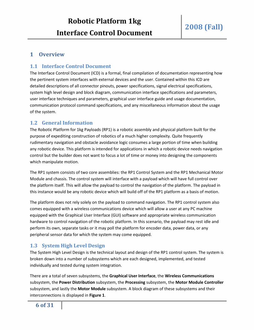
1.3 System High Level Design
The System High Level Design is the technical layout and design of the RP1 control system. The system is
broken down into a number of subsystems which are each designed, implemented, and tested
individually and tested during system integration.
There are a total of seven subsystems, the Graphical User Interface, the Wireless Communications
subsystem, the Power Distribution subsystem, the Processing subsystem, the Motor Module Controller
subsystem, and lastly the Motor Module subsystem. A block diagram of these subsystems and their
interconnections is displayed in Figure 1.

Robotic Platform 1kg 2008 (Fall)
Interface Control Document
7 of 31
The Graphical User Interface (GUI) is a software application written in JAVA and is thusly cross platform
compatible. Any operating system running the JAVA JRE (Java Runtime Environment) will be able to run
the GUI client software. The details of the GUI are described in section 3.
The Wireless Communications subsystem is a subsystem dedicated to maintaining wireless control over
the robotic platform. The details of the communication properties of this subsystem are described in
section 2.6. The details of the communications protocol shared by both wireless and wired
communications channels are described in section 4.
The Processing subsystem is the computational heart of the robotic platform. This subsystem contains
the processing core which computes all commands issued through the communication channel into
motor controls and sensor feedback to the user. The details of this subsystem are not relevant within
the scope of the ICD, for more information please reference the Customer Needs, Design Specifications,
and any design documentation which may pertain to the Processing subsystem.
The Motor Module Controller subsystem and subsequent Motor Module subsystem are the logic and
device systems for actuating a motor. The Motor Module Controller subsystem contains logic to actuate
a motor, but does not contain the motor or driver circuitry itself. The controller subsystem simply
generates the timing and control signals which are then fed into the Motor Module subsystem. There
are a variety of Motor Module controllers for the various supported motors. DC and Stepper motors
required extra controller and timing circuitry to operate, while Servos require only Pulse Width
Modulation (PWM) input. DC and Stepper motors require PWM inputs as well. Moving PWM generation
responsibility off chip onto a separate microcontroller, identified in the diagram as the PID Controller
module will allow for increased system modularity and less load on the core processing system.
The Motor Module system is not part of the RP1 control system platform, but is mentioned here only for
clarity of the design. The Motor Module will interface with the RP1 control system through the electrical
interface defined in section 2.3. The Motor Module is expected to utilize the timing signals specified in
this interface to control driver circuitry and the motor. The driver circuitry, whether this will be a motor
H-Bridge or some other device, shall be contained within the Motor Module itself and not within the
RP1 control system.

Robotic Platform 1kg
Interface Control Document
8 of 31
2 Physical Interface All connector and cabling information is stored on the P09204 EDGE website within the Design Data
subpage, https://edge.rit.edu/content/P09204/public/Design%20Data?rev=0#Wiring
interface pinouts are redefined here, but all connector models and genders, wire
and interconnection is defined on the EDGE website mentioned above.
2.1 Control System Chassis
2.1.1 Chassis Diagram
TBD
2.1.2 Physical Dimensions
TBD
Robotic Platform 1kg 2008 (Fall)
Interface Control Document
Figure 1 - System Level Block Diagram
All connector and cabling information is stored on the P09204 EDGE website within the Design Data
https://edge.rit.edu/content/P09204/public/Design%20Data?rev=0#Wiring. For clarity, the
interface pinouts are redefined here, but all connector models and genders, wire lengths and gauges,
and interconnection is defined on the EDGE website mentioned above.
Control System Chassis
2008 (Fall)
All connector and cabling information is stored on the P09204 EDGE website within the Design Data
. For clarity, the
lengths and gauges,

Robotic Platform 1kg 2008 (Fall)
Interface Control Document
9 of 31
2.1.3 External Interconnect
Please reference the Hardware Control Document (HCD) for details on wiring the control system to
external devices.
2.2 Power Interface
The power interface to the control system is a 4-pin Universal MATE-N-LOCK (more commonly known as
a power MOLEX). Two voltage sources are requires, a 12V source for motors and a 9V source for logic.
2.2.1 Connector Pinout
Signal Pin Description
9V/12V Power 1 12V PWR
2 12V RTN
3 5V PWR
4 5V RTN
Figure 2 - Power Connector Pinout
2.2.2 Electrical Properties
Signal Parameter Min Typ Max Units
12V PWR Voltage 7 12 18 V
12V PWR Current <4000mA 10000 mA
9V PWR Voltage 4.5 5 5.5 V
9V PWR Current <500mA 1000 mA
Figure 3 - Power Interface Electrical Properties
2.3 DC Motor Interface
The DC Motor power and logic signals are supplied through a single 10-pin VAL-U-LOK connector on the
chassis. The pinout and signal properties are defined below.
2.3.1 Connector Pinout
Signal Pin Description
DC Motor PWR/Logic 1 12V PWR
2 GND
3 5V PWR
4 GND
5 ~En
6 GND
7 PWM
8 GND
9 FWD/~REV
Robotic Platform 1kg 2008 (Fall)
Interface Control Document
10 of 31
Signal Pin Description
10 GND
Figure 4 - DC Motor Connector Pinout
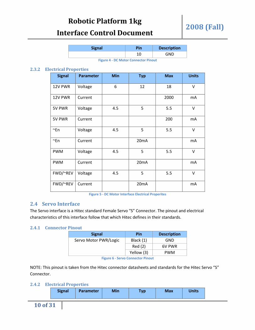
2.3.2 Electrical Properties
Signal Parameter Min Typ Max Units
12V PWR Voltage 6 12 18 V
12V PWR Current 2000 mA
5V PWR Voltage 4.5 5 5.5 V
5V PWR Current 200 mA
~En Voltage 4.5 5 5.5 V
~En Current 20mA mA
PWM Voltage 4.5 5 5.5 V
PWM Current 20mA mA
FWD/~REV Voltage 4.5 5 5.5 V
FWD/~REV Current 20mA mA
Figure 5 - DC Motor Interface Electrical Properites
2.4 Servo Interface
The Servo interface is a Hitec standard Female Servo “S” Connector. The pinout and electrical
characteristics of this interface follow that which Hitec defines in their standards.
2.4.1 Connector Pinout
Signal Pin Description
Servo Motor PWR/Logic Black (1) GND
Red (2) 6V PWR
Yellow (3) PWM
Figure 6 - Servo Connector Pinout
NOTE: This pinout is taken from the Hitec connector datasheets and standards for the Hitec Servo “S”
Connector.
2.4.2 Electrical Properties
Signal Parameter Min Typ Max Units

Robotic Platform 1kg 2008 (Fall)
Interface Control Document
11 of 31
Signal Parameter Min Typ Max Units
6V PWR Voltage 5.5 6 6.5 V
6V PWR Current 2000 mA
PWM Voltage 4.5 5 5.5 V
PWM Current 20mA mA
PWM Frequency Hz
Figure 7 - Servo Interface Electrical Properties
2.5 Encoder Feedback Interface
The Servo interface is a Hitec standard Female Servo “S” Connector. The pinout and electrical
characteristics of this interface follow that which Hitec defines in their standards.
2.5.1 Connector Pinout
Signal Pin Description
Encoder Feedback 1 5V PWR
2 ENCA
3 GND
4 ENCB
Figure 8 – Encoder Feedback Connector Pinout
NOTE: This pinout assumes a single ended (as opposed to differential), quadrature encoder.
2.5.2 Electrical Properties
Signal Parameter Min Typ Max Units
5V PWR Voltage 4.5 5 5.5 V
5V PWR Current 100 mA
ENCA Voltage 4.5 5 5.5 V
ENCA Current 20mA mA
ENCB Voltage 4.5 5 5.5 V
ENCB Current 20mA mA
Figure 9 - – Encoder Feedback Electrical Properties

Robotic Platform 1kg 2008 (Fall)
Interface Control Document
12 of 31
2.6 Programming Interface
The programming interface is the Female DB25 Parallel port on the control box chassis case. This
interface allows the user to reprogram the microcontroller.
2.6.1 Connector Pinout
Signal Pin On uC Description
Programming Interface
(DB25)
1 N/A N/A
2 N/A N/A
3 N/A N/A
4 N/A N/A
5 ISP Header Pin-2 5V PWR
6 N/A N/A
7 ISP Header Pin-5 RESET
8 ISP Header Pin-7 SCK
9 ISP Header Pin-1 MOSI
10 ISP Header Pin-9 MISO
11 N/A N/A
12 N/A N/A
13 N/A N/A
14 N/A N/A
15 N/A N/A
16 N/A N/A
17 N/A N/A
18 N/A N/A
19 N/A N/A
20 N/A N/A
21 N/A N/A
22 N/A N/A
23 ISP Header Pin-4 GND
24 ISP Header Pin-6 GND
25 ISP Header Pin-8 GND
Figure 10 – Programming Interface Connector Pinout
Pin Description
RESET Used to reset the target system under the PC's control.
SCK The serial data clock
MOSI Master Out Slave In, used to send data from the PC (master) to the AVR

Robotic Platform 1kg 2008 (Fall)
Interface Control Document
13 of 31
Pin Description
(slave). Data is transmitted on the edges of SCK.
MISO Master In Slave Out, used to send data from the AVR (master) to the PC
(slave). Data is transmitted on the edges of SCK.
PWR
Can be used either to provide power to the target system during
programming, or for the programmer to draw power from the target
system during programming.
Figure 11 - Programming Pin Descriptions
2.6.2 Electrical Properties
This connection follows the electrical standards of a PC parallel port. A good review of the parallel port
electrical standards is described on the website:
http://www.circlemud.org/jelson/software/parapin/docs/node2.html
2.7 Wired and Tethered Communications Link
The Wired/Tethered Communications interface is a female DB9 RS232 Serial channel. Operating
parameters are defined in Section 4.2.1 below.
2.7.1 Connector Pinout
Signal Pin Description
Serial RS232 (DB9) 1 Pin 4, 6
2 PC Rx
3 PC Tx
4 Pin 1, 6
5 GND
6 Pin 1, 4
7 Pin 8
8 Pin 7
9 5V
Figure 12 – Wired Communications Link Connector Pinout
NOTE: Pins 1, 4, and 6 are all connected together as these signals loop back on each other. Pins 7 and 8
are connected together.
These signals behave according to the RS232 standards.

Robotic Platform 1kg 2008 (Fall)
Interface Control Document
14 of 31
2.7.2 Electrical Properties
This connector has the electrical properties specified by the RS232 standards.
2.8 Wireless Communications Link
The Wireless Communications Link is implemented as an IOGear Wireless Bluetooth device external to
the box. The IOGear Wireless Bluetooth device has an RS232 serial connector that can interface directly
to the second RS232 channel external to the RP Control Box. Configuration of this device is specified in
the operating manual, but for convenience is described again below.
To enter device configuration panel, open a terminal connection to an available serial port of a desktop
PC. Configure the terminal for 8N1 (8 data bits, no parity, 1 stop bit) communication with no flow
control. Configure the baud rate to be 9600. Make sure the DIP switches of the adapter are all set to
‘ON’ state. Now, connect the IOGear adapter to this serial port and monitor the terminal. After the
device sends “PC” there is a 6 second window to type “AT”. When the command is entered a
configuration panel will appear. Follow the on screen directions to configure the device.
A note on adapter pairing; one adapter needs to be configured as MASTER and the second as SLAVE. The
4th
DIP switch controls this. When set to ‘ON’ the device acts as MASTER and will initiate pairing with its
programmed SLAVE device. When SLAVE it will await pairing from its programmed MASTER. After both
MASTER and SLAVE are turned on, the MASTER will automatically attempt to pair with its SLAVE adapter
and there is an approximate 30 second window from power-up in which it does this. After 30 seconds
there should be communication between MASTER and SLAVE.
To configure the adapter for a 38400 BAUD, DIP switches 1 and 3 are ‘ON’ and 2 is ‘OFF’. DIP switch 4 is
‘ON’ for the MASTER adapter and ‘OFF’ for the SLAVE adapter.
2.9 Two-Wire Interface (I2C)
The RP1 Control System can communicate with external devices utilizing the Two-Wire Interface (TWI),
otherwise known as the I2C data bus. Devices need only plug into the external TWI port located on the
RP1 control system chassis and communicate with the device through software.
There are limitations to the TWI device addresses that can be used by an external device due to the
address use of the Motor Module Controllers within the control system. The reserved addresses and
their corresponding device descriptions are listed in Figure 13.
Internal Assembly Reserved Address
PID_CTRL-A 0xBA
PID_CTRL-B 0xBB
PID_CTRL-C 0xBC
PID_CTRL-D 0xBD Figure 13 - Reserved TWI Addresses

Robotic Platform 1kg 2008 (Fall)
Interface Control Document
15 of 31
There are safety precautions when using this external port. The TWI bus is a 100kHz, 400pF maximum
capacity bus and is not meant for cabling of significant length. Long wires may introduce excessive noise
to the bus and could potentially cause bus errors.
2.9.1 Connector Pinout
Signal Pin Description
TWI PWR/Logic 1 5V PWR
2 GND
3 SCL
4 SDA
Figure 14 - TWI Connector Pinout
2.9.2 Electrical Properties
Signal Parameter Min Typ Max Units
5V PWR Voltage 4.5 5 5.5 V
5V PWR Current 200 mA
SCL Voltage 4.5 5 5.5 V
SCL Current 20mA mA
SCL Frequency 100kHz 100kHz 400kHz Hz
SDA Voltage 4.5 5 5.5 V
SDA Current 20mA mA
SDA Frequency 400kHz Hz
Figure 15 - TWI Interface Electrical Properties
NOTE: There are no voltage clamps or isolation circuits on control lines SCL and SDA, so use caution
when manipulating these lines external to the device! Misuse of these signals could cause the system to
become unstable. External TWI data line usage is for advanced users only.
3 Graphical User Interface
3.1 General Information
Please reference the Software Control Document (SCD) for details on the Graphical User Interface
design and walkthrough. Please see section 6 below for the location of the SCD.
Robotic Platform 1kg 2008 (Fall)
Interface Control Document
16 of 31
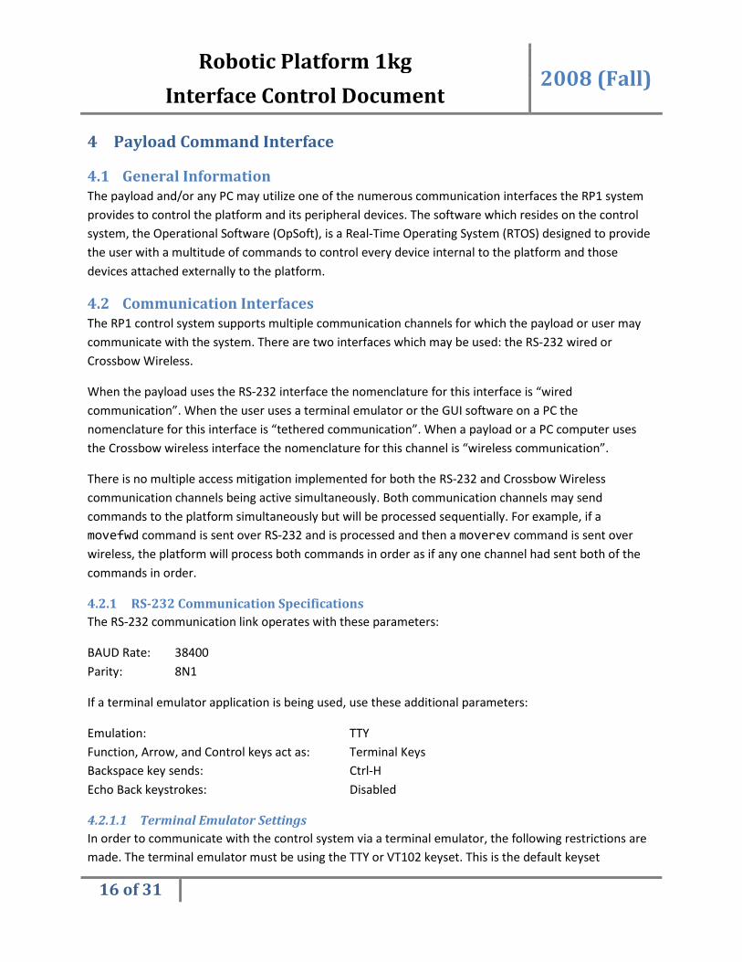
4 Payload Command Interface
4.1 General Information
The payload and/or any PC may utilize one of the numerous communication interfaces the RP1 system
provides to control the platform and its peripheral devices. The software which resides on the control
system, the Operational Software (OpSoft), is a Real-Time Operating System (RTOS) designed to provide
the user with a multitude of commands to control every device internal to the platform and those
devices attached externally to the platform.
4.2 Communication Interfaces
The RP1 control system supports multiple communication channels for which the payload or user may
communicate with the system. There are two interfaces which may be used: the RS-232 wired or
Crossbow Wireless.
When the payload uses the RS-232 interface the nomenclature for this interface is “wired
communication”. When the user uses a terminal emulator or the GUI software on a PC the
nomenclature for this interface is “tethered communication”. When a payload or a PC computer uses
the Crossbow wireless interface the nomenclature for this channel is “wireless communication”.
There is no multiple access mitigation implemented for both the RS-232 and Crossbow Wireless
communication channels being active simultaneously. Both communication channels may send
commands to the platform simultaneously but will be processed sequentially. For example, if a
movefwd command is sent over RS-232 and is processed and then a moverev command is sent over
wireless, the platform will process both commands in order as if any one channel had sent both of the
commands in order.
4.2.1 RS-232 Communication Specifications
The RS-232 communication link operates with these parameters:
BAUD Rate: 38400
Parity: 8N1
If a terminal emulator application is being used, use these additional parameters:
Emulation: TTY
Function, Arrow, and Control keys act as: Terminal Keys
Backspace key sends: Ctrl-H
Echo Back keystrokes: Disabled
4.2.1.1 Terminal Emulator Settings
In order to communicate with the control system via a terminal emulator, the following restrictions are
made. The terminal emulator must be using the TTY or VT102 keyset. This is the default keyset

Robotic Platform 1kg 2008 (Fall)
Interface Control Document
17 of 31
supported by Windows HyperTerminal. In addition, the emulator must send backspace keystrokes as
Ctrl-H keystrokes (also the default for HyperTerminal). Command Line Interface (CLI) operation is
dependent upon these restrictions.
Windows HyperTerminal can be located in the default installation of any Windows 9x, 2000/NT, or XP
operating system. HyperTerminal is located under the Start Menu within folder:
Start Menu -> Programs -> Accessories -> Communications
When creating a new terminal connection, please use the configuration parameters defined in section
4.2.1.1.
4.3 Command Protocol
The RP1 Control System will provide a rudimentary Command Line Interface (CLI) for which the user or
payload using any communication channel shall utilize to send commands to the platform and all
attached peripherals. The CLI and all commands implemented by the Operational Software (OpSoft) are
described in the sections following.
4.3.1 General Information
The CLI supports a number of ASCII commands to be sent over any communication channel specified in
section 4.2. The CLI has a specific usage that should be understood before commands are sent. It is
possible to send these commands using a terminal interface such as Windows HyperTerminal, but the
GUI software is recommended in its place.
The CLI command line prompt is printed out at system power up and after each received command has
been processed. The CLI command prompt displayed, when using a terminal emulator, will appear as:
>>
It should be noted that a single space follows the characters “>>”. Commands entered in from this
prompt will be buffered by the controller until a newline feed is read (an enter keystroke). All keystrokes
will be echoed back to the user until the maximum number of characters per command is reached. The
CLI can support a total of 512 characters per command, which is more than sufficient for any command
implemented in the command set.
If a user enters a command which is not implemented in the command protocol, the CLI will respond
with an error message. The error message as it appears:
BADCOMMAND
4.3.2 Wheel Matrix
The Wheel Matrix is a software paradigm for how the motor modules are organized and controlled with
respect to the RP chassis. The software must have knowledge of where the motors reside, both drive

Robotic Platform 1kg 2008 (Fall)
Interface Control Document
18 of 31
and steer, how they are grouped, and the motor type and parameters. The Wheel Matrix attempts to
solve the problem of how software knows where the motors reside with respect to the core physical
chassis, and this is described below.
The Wheel Matrix is a 2-dimensional software matrix serialized to be a 1-dimensional software array. In
layman’s terms, it is a list of all the motor modules which could possibly be attached to the Robotic
Platform chassis. Each index of the list has a predefined, known, physical location. These locations are
defined in Figure 16 below. If a motor module is to be mounted on the chassis it *must* be located in
one of the defined positions. If a motor module is mounted elsewhere on the chassis then this model
must be updated in documentation and software to reflect that new position.
Figure 16 - Chassis and Motor Module Top-View
4.3.3 Configuration Command Set
The Robotic Platform needs to be aware of the physical characteristics of the motors attached to it in
order to properly navigate and make full use of its navigation logic. All configuration data is stored in
EEPROM memory and will reside after system reboot. All configuration data is made available to the
robot immediately after configuration without the need to reboot the robot.
Robotic Platform 1kg 2008 (Fall)
Interface Control Document
19 of 31
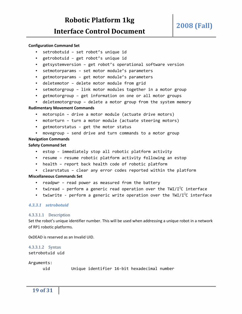
Configuration Command Set
• setrobotuid – set robot’s unique id
• getrobotuid – get robot’s unique id
• getsystemversion – get robot’s operational software version
• setmotorparams – set motor module’s parameters
• getmotorparams – get motor module’s parameters
• deletemotor – delete motor module from grid
• setmotorgroup – link motor modules together in a motor group
• getmotorgroup – get information on one or all motor groups
• deletemotorgroup – delete a motor group from the system memory
Rudimentary Movement Commands
• motorspin – drive a motor module (actuate drive motors)
• motorturn – turn a motor module (actuate steering motors)
• getmotorstatus – get the motor status
• movegroup – send drive and turn commands to a motor group
Navigation Commands
Safety Command Set
• estop – immediately stop all robotic platform activity
• resume – resume robotic platform activity following an estop
• health – report back health code of robotic platform
• clearstatus – clear any error codes reported within the platform
Miscellaneous Commands Set
• readpwr – read power as measured from the battery
• twiread – perform a generic read operation over the TWI/I2C interface
• twiwrite - perform a generic write operation over the TWI/I2C interface
4.3.3.1 setrobotuid
4.3.3.1.1 Description
Set the robot’s unique identifier number. This will be used when addressing a unique robot in a network
of RP1 robotic platforms.
0xDEAD is reserved as an Invalid UID.
4.3.3.1.2 Syntax
setrobotuid uid
Arguments:
uid Unique identifier 16-bit hexadecimal number

Robotic Platform 1kg 2008 (Fall)
Interface Control Document
20 of 31
Return:
“OK” Unique identifier stored in EEPROM
“INVARG” Invalid number of, or invalid format of arguments
“SYSFAIL” Unknown system failure
4.3.3.2 getrobotuid
4.3.3.2.1 Description
Return the configured robot unique identifier.
0xDEAD is reserved as an Invalid UID.
4.3.3.2.2 Syntax
getrobotuid
Arguments:
None
Return:
“uid” A 16-bit numerical number represented in
hex format (i.e. 0xFFFFFFFF)
A uid of 0x00000000 indicates an unconfigured and
non-networkable robotic platform, must be given
a UID using `setrobotuid 0x########`
“SYSFAIL” Unknown system failure
4.3.3.3 getsystemversion
4.3.3.3.1 Description
Return the operating system version number. If this command returns “0.0.0” then it is assumed that
the RP unit is loaded with a developer’s build.
4.3.3.3.2 Syntax
getsystemversion
Arguments:
None
Return:
“N.M.K” A string value representing the operational
software version the robotic platform is
loaded with (i.e. “1.0.0”, “1.5.2”, etc…)
Significance of the version numbers will be
detailed in this document and the SCD
Robotic Platform 1kg 2008 (Fall)
Interface Control Document
21 of 31
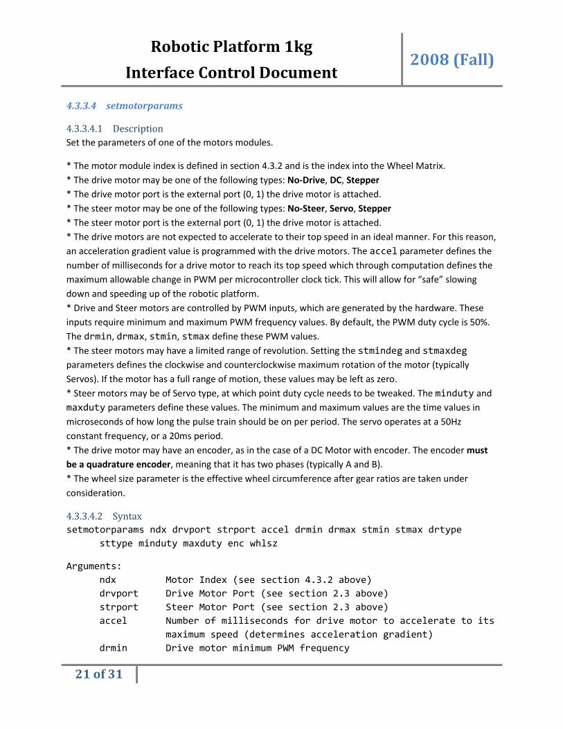
4.3.3.4 setmotorparams
4.3.3.4.1 Description
Set the parameters of one of the motors modules.
* The motor module index is defined in section 4.3.2 and is the index into the Wheel Matrix.
* The drive motor may be one of the following types: No-Drive, DC, Stepper
* The drive motor port is the external port (0, 1) the drive motor is attached.
* The steer motor may be one of the following types: No-Steer, Servo, Stepper
* The steer motor port is the external port (0, 1) the drive motor is attached.
* The drive motors are not expected to accelerate to their top speed in an ideal manner. For this reason,
an acceleration gradient value is programmed with the drive motors. The accel parameter defines the
number of milliseconds for a drive motor to reach its top speed which through computation defines the
maximum allowable change in PWM per microcontroller clock tick. This will allow for “safe” slowing
down and speeding up of the robotic platform.
* Drive and Steer motors are controlled by PWM inputs, which are generated by the hardware. These
inputs require minimum and maximum PWM frequency values. By default, the PWM duty cycle is 50%.
The drmin, drmax, stmin, stmax define these PWM values.
* The steer motors may have a limited range of revolution. Setting the stmindeg and stmaxdeg
parameters defines the clockwise and counterclockwise maximum rotation of the motor (typically
Servos). If the motor has a full range of motion, these values may be left as zero.
* Steer motors may be of Servo type, at which point duty cycle needs to be tweaked. The minduty and
maxduty parameters define these values. The minimum and maximum values are the time values in
microseconds of how long the pulse train should be on per period. The servo operates at a 50Hz
constant frequency, or a 20ms period.
* The drive motor may have an encoder, as in the case of a DC Motor with encoder. The encoder must
be a quadrature encoder, meaning that it has two phases (typically A and B).
* The wheel size parameter is the effective wheel circumference after gear ratios are taken under
consideration.
4.3.3.4.2 Syntax
setmotorparams ndx drvport strport accel drmin drmax stmin stmax drtype
sttype minduty maxduty enc whlsz
Arguments:
ndx Motor Index (see section 4.3.2 above)
drvport Drive Motor Port (see section 2.3 above)
strport Steer Motor Port (see section 2.3 above)
accel Number of milliseconds for drive motor to accelerate to its
maximum speed (determines acceleration gradient)
drmin Drive motor minimum PWM frequency

Robotic Platform 1kg 2008 (Fall)
Interface Control Document
22 of 31
drmax Drive motor maximum PWM frequency
stmin Steer motor minimum PWM frequency
stmax Steer motor maximum PWM frequency
drtype Drive motor type (0 = None, 1 = DC, 2 = Stepper)
sttype Steer motor type (0 = None, 1 = Servo, 2 = Stepper)
minduty Minimum duty cycle (for servos only) in microseconds
(i.e. 540)
maxduty Maximum duty cycle (for servos only) in microseconds
(i.e. 2400)
enc Encoder pulses per revolution per phase (0 for no encoder)
whlsz Wheel circumference (in cm)
Return:
“OK” Motor parameters stored correctly in EEPROM
“BADINDEX” Invalid motor index
“BADPORT” Invalid motor port
“BADFREQ” Bad minimum or maximum specified frequency
“BADTYPE” Bad motor type
“BADDEGREES” Invalid degrees specification (-180 to 180)
“BADDUTY” Invalid duty cycle specified
“BADENC” Bad encoder pulses per revolution
“BADWHEELSIZE” Bad wheel diameter
“INVARG” Invalid number of, or invalid format of arguments
“SYSFAIL” Unknown system failure
4.3.3.5 getmotorparams
4.3.3.5.1 Description
Get and return all parameters for the motor, space delimited.
4.3.3.5.2 Syntax
getmotorparams ndx
Arguments:
ndx Motor Index (see section 4.3.2 above)
Return:
“drvport strport accel drmin drmax stmin stmax drtype sttype
minduty maxduty enc whlsz”
Returns a space delimited list of parameters associated with the
motor, see setmotorparams for details on each parameter
“BADINDEX” Invalid motor index
“SYSFAIL” Unknown system failure

Robotic Platform 1kg 2008 (Fall)
Interface Control Document
23 of 31
4.3.3.6 deletemotor
4.3.3.6.1 Description
Remove a motor module from the system.
4.3.3.6.2 Syntax
deletemotor ndx
Arguments:
ndx Motor Index (see section 4.3.2 above)
Return:
“OK” Motor module configuration deleted, motor detached
“BADINDEX” Invalid motor index
“INVARG” Invalid number of, or invalid format of arguments
“SYSFAIL” Unknown system failure
4.3.3.7 setmotorgroup
4.3.3.7.1 Description
Make or overwrite a group of motors. Maximum of 16 motor groups. The maximum numbers of motors
is the maximum number of motor modules that may be configured with setmotorparams.
4.3.3.7.2 Syntax
setmotorgroup ndx type motorndx1 [motorndx2] … [motorndxN]
Arguments:
ndx Motor Group Index (0 … 15)
type Group type (0 = Drive Only, 1 = Steering Only,
2 = Driving and Steering)
motorndxN Motor Index (see section 4.3.2 above)
Return:
“OK” Motor
“BADINDEX” Group or motor index is invalid
“BADTYPE” Group type is invalid
“INVARG” Invalid number of, or invalid format of arguments
“SYSFAIL” Unknown system failure
4.3.3.8 getmotorgroup
4.3.3.8.1 Description
Get motor group information.

Robotic Platform 1kg 2008 (Fall)
Interface Control Document
24 of 31
4.3.3.8.2 Syntax
getmotorgroup ndx
Arguments:
ndx Motor Group Index (0 … 15)
Return:
“type motorndx1 motorndx2 … motorndxN”
Lists one or more motors associated with the group and the group
type (drive, steer, both)
“NOGROUP” Group does not exist
“INVARG” Invalid number of, or invalid format of arguments
“SYSFAIL” Unknown system failure
4.3.3.9 deletemotorgroup
4.3.3.9.1 Description
Delete a motor group from the configuration set.
4.3.3.9.2 Syntax
deletemotorgroup ndx
Arguments:
ndx Motor Group Index (0 … 15)
Return:
“OK” Group deleted from the configuration
“BADINDEX” Group or motor index is invalid
“INVARG” Invalid number of, or invalid format of arguments
“SYSFAIL” Unknown system failure
4.3.4 Rudimentary Movement Commands
These commands control movement on a per-motor or system basis. Advanced navigation is not part of
this command set category and is located in section 4.3.5 of the Navigation Commands command set.
All commands involving speed are defined between values 0 and 65535 with units of centimeters per
second.
4.3.4.1 motorspin
4.3.4.1.1 Description
Spin the drive motor to move forward or reverse. Note that motor acceleration parameters affect when
the motor will reach the programmed speed. Note that certain speeds are not attainable by the motor
modules (i.e. 32767 is 733 miles per hour).

Robotic Platform 1kg 2008 (Fall)
Interface Control Document
25 of 31
4.3.4.1.2 Syntax
motorspin motorndx speed
Arguments:
motorndx Motor Index (see section 4.3.2 above)
speed Motor Speed (-32768 – 32767 cm/s)
Return:
“OK” Motor speed set, command OK
“BADINDEX” Motor index is invalid
“BADSPEED” The specified speed is invalid
“BUSFAIL” TWI bus error encountered
“INVARG” Invalid number of, or invalid format of arguments
“SYSFAIL” Unknown system failure
4.3.4.2 motorturn
4.3.4.2.1 Description
Actuate steer motors to rotate the driver motor of a motor module.
4.3.4.2.2 Syntax
motorturn motorndx degrees
Arguments:
motorndx Motor Index (see section 4.3.2 above)
degrees Number of degrees to rotate (0 to 180), a degrees
input of 90 re-centers the wheel
Return:
“OK” Steering motor turning OK
“BADINDEX” Invalid motor index
“BADDEGREES” Number of degrees is invalid
“BUSFAIL” TWI bus error encountered
“INVARG” Invalid number of, or invalid format of arguments
“SYSFAIL” Unknown system failure
4.3.4.3 getmotorstatus
4.3.4.3.1 Description
Return the current speed and rotation status of a motor module.
4.3.4.3.2 Syntax
getmotorstatus motorndx

Robotic Platform 1kg 2008 (Fall)
Interface Control Document
26 of 31
Arguments:
motorndx Motor Index (see section 4.3.2 above)
Return:
“prgmspeed curspeed degrees”
prgmspeed – a decimal value of the programmed speed
(-32768 – 32767 cm/s)
curspeed – a decimal value of the current speed
(-32768 – 32767 cm/s)
degrees – current programmed value of wheel angle in degrees,
(0 – 180, 90 being centered in degrees)
“BADINDEX” Invalid motor index
“BUSFAIL” TWI bus error encountered
“INVARG” Invalid number of, or invalid format of arguments
“SYSFAIL” Unknown system failure
4.3.4.4 movegroup
4.3.4.4.1 Description
Set drive motor speed and direction and steering motor degrees of rotation of an entire motor group.
This essentially performs a motorspin and motorturn command on every motor specified in a defined
motor group.
4.3.4.4.2 Syntax
movegroup groupndx speed degrees
Arguments:
groupndx Motor Group Index (0 … 15)
speed Motor Speed (-32768 – 32767)
degrees Number of degrees to rotate (0 to 180), a degrees
input of 90 re-centers the wheel
Return:
“OK” Group of motors configured to move and turn
“BADINDEX” Invalid motor group index (1 … 15)
“BADSPEED” The specified speed is invalid
“BADDEGREES” Number of degrees is invalid
“BUSFAIL” TWI bus error encountered
“INVARG” Invalid number of, or invalid format of arguments
“SYSFAIL” Unknown system failure
Robotic Platform 1kg 2008 (Fall)
Interface Control Document
27 of 31
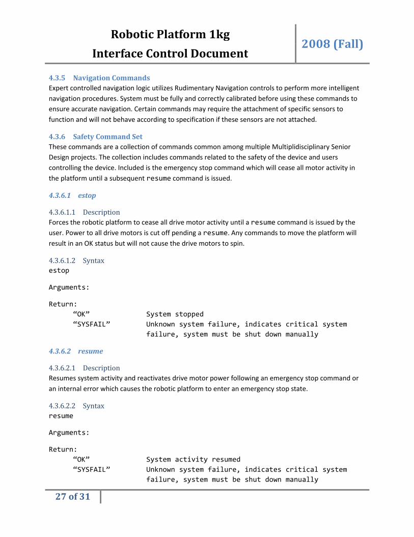
4.3.5 Navigation Commands
Expert controlled navigation logic utilizes Rudimentary Navigation controls to perform more intelligent
navigation procedures. System must be fully and correctly calibrated before using these commands to
ensure accurate navigation. Certain commands may require the attachment of specific sensors to
function and will not behave according to specification if these sensors are not attached.
4.3.6 Safety Command Set
These commands are a collection of commands common among multiple Multiplidisciplinary Senior
Design projects. The collection includes commands related to the safety of the device and users
controlling the device. Included is the emergency stop command which will cease all motor activity in
the platform until a subsequent resume command is issued.
4.3.6.1 estop
4.3.6.1.1 Description
Forces the robotic platform to cease all drive motor activity until a resume command is issued by the
user. Power to all drive motors is cut off pending a resume. Any commands to move the platform will
result in an OK status but will not cause the drive motors to spin.
4.3.6.1.2 Syntax
estop
Arguments:
Return:
“OK” System stopped
“SYSFAIL” Unknown system failure, indicates critical system
failure, system must be shut down manually
4.3.6.2 resume
4.3.6.2.1 Description
Resumes system activity and reactivates drive motor power following an emergency stop command or
an internal error which causes the robotic platform to enter an emergency stop state.
4.3.6.2.2 Syntax
resume
Arguments:
Return:
“OK” System activity resumed
“SYSFAIL” Unknown system failure, indicates critical system
failure, system must be shut down manually

Robotic Platform 1kg 2008 (Fall)
Interface Control Document
28 of 31
4.3.6.3 health
4.3.6.3.1 Description
Reports back to the user the health status of the system.
4.3.6.3.2 Syntax
health
Arguments:
Return:
“OK” System in a healthy, non-stopped state
“STOPPED” System is in emergency stop, but no errors have been
logged internally
“MINOR” System has encountered one or more minor errors,
this return code may be followed by a string
description of the error(s) (multiple lines)
“MINORSTOPPED” A combination of MINOR and STOPPED states
“MAJOR” System has encountered a major error, when a major
error occurs the system is automatically placed into
emergency stop as well, this return code may be
followed by a string description of the error(s)
(multiple lines)
“SYSFAIL” Unknown system failure, indicates critical system
failure, system must be shut down manually
4.3.6.4 clearstatus
4.3.6.4.1 Description
If the health code is MINOR, then the health status code logs are cleared.
4.3.6.4.2 Syntax
clearstatus
Arguments:
Return:
“OK” Status code cleared
“NOTOK” Status code not cleared, the error level is too
critical to be ignored, system must be shut down
for manual maintenance and diagnostics
“SYSFAIL” Unknown system failure, indicates critical system
failure, system must be shut down manually
Robotic Platform 1kg 2008 (Fall)
Interface Control Document
29 of 31
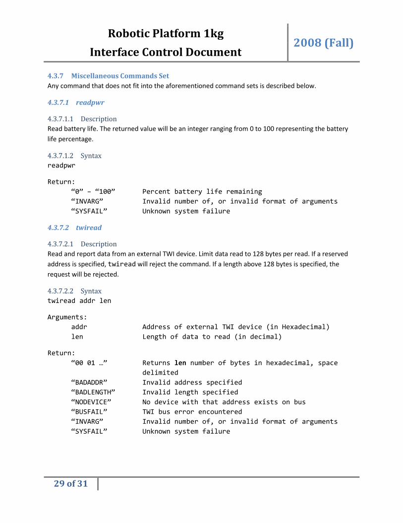
4.3.7 Miscellaneous Commands Set
Any command that does not fit into the aforementioned command sets is described below.
4.3.7.1 readpwr
4.3.7.1.1 Description
Read battery life. The returned value will be an integer ranging from 0 to 100 representing the battery
life percentage.
4.3.7.1.2 Syntax
readpwr
Return:
“0” – “100” Percent battery life remaining
“INVARG” Invalid number of, or invalid format of arguments
“SYSFAIL” Unknown system failure
4.3.7.2 twiread
4.3.7.2.1 Description
Read and report data from an external TWI device. Limit data read to 128 bytes per read. If a reserved
address is specified, twiread will reject the command. If a length above 128 bytes is specified, the
request will be rejected.
4.3.7.2.2 Syntax
twiread addr len
Arguments:
addr Address of external TWI device (in Hexadecimal)
len Length of data to read (in decimal)
Return:
“00 01 …” Returns len number of bytes in hexadecimal, space
delimited
“BADADDR” Invalid address specified
“BADLENGTH” Invalid length specified
“NODEVICE” No device with that address exists on bus
“BUSFAIL” TWI bus error encountered
“INVARG” Invalid number of, or invalid format of arguments
“SYSFAIL” Unknown system failure

Robotic Platform 1kg 2008 (Fall)
Interface Control Document
30 of 31
4.3.7.3 twiwrite
4.3.7.3.1 Description
Write data to an external TWI device. Limit data length to 128 bytes per write. If a reserved address is
specified, twiwrite will reject the command. The command will ignore any data byte beyond the 128th
byte.
4.3.7.3.2 Syntax
twiwrite addr data1 data2 … dataN
Arguments:
addr Address of external TWI device (in Hexadecimal)
data1 … dataN Bytes of data in hexadecimal, space delimited
Return:
“OK” TWI write successful, command OK
“BADADDR” Invalid address specified
“NODEVICE” No device with that address exists on bus
“BUSFAIL” TWI bus error encountered
“INVARG” Invalid number of, or invalid format of arguments
“SYSFAIL” Unknown system failure
4.3.8 Diagnostics Commands
This set of commands is for developer use only and is not utilized by the GUI client software in any
fashion. These commands aid the developer in debugging hardware or software problems and are
included here for convenience.
5 Acronyms
Acronym Description
RP1 Robotic Platform 1
ICD Interface Control Document
GUI Graphical User Interface
JRE JAVA Runtime Environment
CLI Command Line Interface
OpSoft Operational Software
RTOS Real Time Operating System
PC Personal Computer (Desktop or Laptop)
SCD Software Control Document
HCD Hardware Control Document
Figure 17 - Table of Acronyms

Robotic Platform 1kg 2008 (Fall)
Interface Control Document
31 of 31
6 Document References
Document Location or Link
Customer Needs https://edge.rit.edu/content/P09204/public/documentation/Needs%20Assessment.xls
Design Specifications https://edge.rit.edu/content/P09204/public/documentation/Design%20Specifications.xls
Software Control
Document
https://edge.rit.edu/content/P09204/public/documentation/Hardware%20Control%20Document.docx
Hardware Control
Document
https://edge.rit.edu/content/P09204/public/documentation/Software%20Control%20Document.docx
Figure 18 - Table of References