interaction modelling: sequence diagrams - ut · interaction modelling: sequence diagrams fabrizio...
TRANSCRIPT

Interaction Modelling: Sequence Diagrams
Fabrizio Maria Maggi
Institute of Computer Science
(these slides are derived from the book “Object-oriented modeling and design with UML”)

1 Systems modelling – Fabrizio Maria Maggi
Interaction Modelling: Detailing
Use Cases with Scenarios

2 Systems modelling – Fabrizio Maria Maggi
Interaction Modelling

3
� A sequence diagram shows the participants in an
interaction and the sequence of messages among them
� A sequence diagram shows the interaction of a system with
its actors to perform a use case
Systems modelling – Fabrizio Maria Maggi
Sequence Diagrams
4 Systems modelling – Fabrizio Maria Maggi
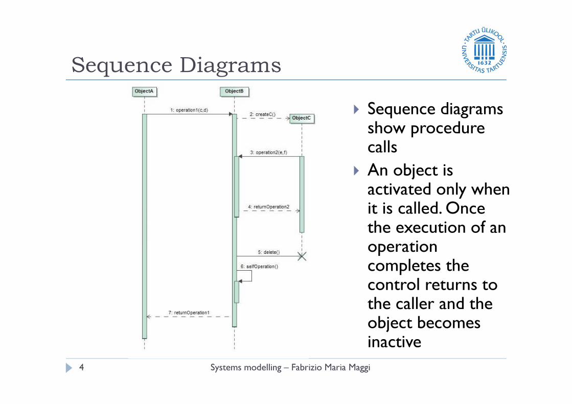
Sequence Diagrams
� Sequence diagrams show procedure calls
� An object is activated only when it is called. Once the execution of an operation completes the control returns to the caller and the object becomes inactive

5 Systems modelling – Fabrizio Maria Maggi
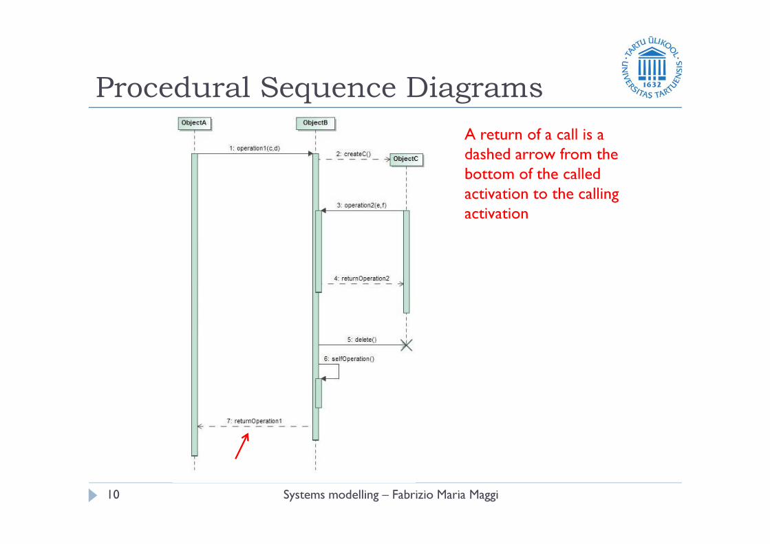
Procedural Sequence Diagrams
The period of time of an
object’s execution is a thin
rectangle called activation
or focus of control

6 Systems modelling – Fabrizio Maria Maggi
Procedural Sequence Diagrams
An activation shows the
time period during which a
call of a method is
processed including the
time when the called
method invoke other
methods

7 Systems modelling – Fabrizio Maria Maggi
Procedural Sequence Diagrams
The period of time when
an object exists but is not
active is shown as a dashed
line

8 Systems modelling – Fabrizio Maria Maggi
Procedural Sequence Diagrams
The entire period of time
when an object exists is
called lifeline

9 Systems modelling – Fabrizio Maria Maggi
Procedural Sequence Diagrams
The notation for a call
(synchronous message) is
an arrow from the calling
activation to the activation
created by the call.
10 Systems modelling – Fabrizio Maria Maggi
Procedural Sequence Diagrams
A return of a call is a
dashed arrow from the
bottom of the called
activation to the calling
activation

11 Systems modelling – Fabrizio Maria Maggi
Procedural Sequence Diagrams
An activation has a call
arrow coming into its top
and a return arrow leaving
its bottom

12 Systems modelling – Fabrizio Maria Maggi
Procedural Sequence Diagrams
Objects A and B exist
during the entire time
shown in the diagram,
whereas object C is
created and destroyed in a
smaller period of time.
Therefore, its lifetime does
not span the whole
diagram

13 Systems modelling – Fabrizio Maria Maggi
Procedural Sequence Diagrams
If an object does not exist
at the beginning of the
sequence diagram, it must
be created. UML shows
creation by placing the
object symbol at the head
of the dashed arrow
representing the call that
creates the object

14 Systems modelling – Fabrizio Maria Maggi
Procedural Sequence Diagrams
A large ‘X’ marks the end
of the life of an object that
is destroyed during the
sequence diagram. The ‘X’
is placed at the head of the
call arrow that destroys
the object

15 Systems modelling – Fabrizio Maria Maggi
Procedural Sequence Diagrams
During a call to a method
on an object there can be
another call to another
method on the same
object. This call is shown
with an arrow from the
activation rectangle to the
top of an additional
rectangle superimposed on
the first

16 Systems modelling – Fabrizio Maria Maggi
Procedural Sequence Diagrams
An object can call its own
operations (self calls)

A simple example
Systems modelling – Fabrizio Maria Maggi17
http://www.ibm.com

Advanced Sequence Diagrams: alt
Systems modelling – Fabrizio Maria Maggi18
http://www.ibm.com

Advanced Sequence Diagrams: opt
Systems modelling – Fabrizio Maria Maggi19
http://www.ibm.com

Advanced Sequence Diagrams: loop
System modelling – Fabrizio Maria Maggi20
http://www.ibm.com

Advanced Sequence Diagrams: break
System modelling – Fabrizio Maria Maggi21
http://www.ibm.com

Closing the circle
System modelling – Fabrizio Maria Maggi22
http://www.ibm.com

From a Domain model to
an Application model
System modelling – Fabrizio Maria Maggi23
http://www.ibm.com

From a Domain model to
an Application model
System modelling – Fabrizio Maria Maggi24
http://www.ibm.com