object-oriented design - university of iowauser.engineering.uiowa.edu/~kuhl/softeng/slides6.pdf ·...
TRANSCRIPT
1
Object-Oriented Design
• Objective: Develop logical solution thatfulfills the requirements– define the classes that will be implemented in
an object-oriented programming language.– Assign responsibilities to software components– Identify and apply design patterns.
Artifacts of Analysis/ArchitecturalModeling
• Conceptual Model– Static Structure diagram(s)– Sequence diagrams– Glossary– Other models and documents?
• Architectural Model– Stakeholder Needs– Architectural views

2
Larman’s Approach to Design
• Develop real use cases• Create interaction diagrams• Develop design class diagrams• Key issues:
– Allocation of responsibility– Identification/application of design pattens
Design--Real Use Cases• Real use cases describe user interaction
with the system in concrete terms.– User interactions with system interface(s)– System interaction with interfaces
• Requires some definition of interfacedetails.
• Remember, the “user” may be anothersoftware system or a hardware systemrather than a human.
3
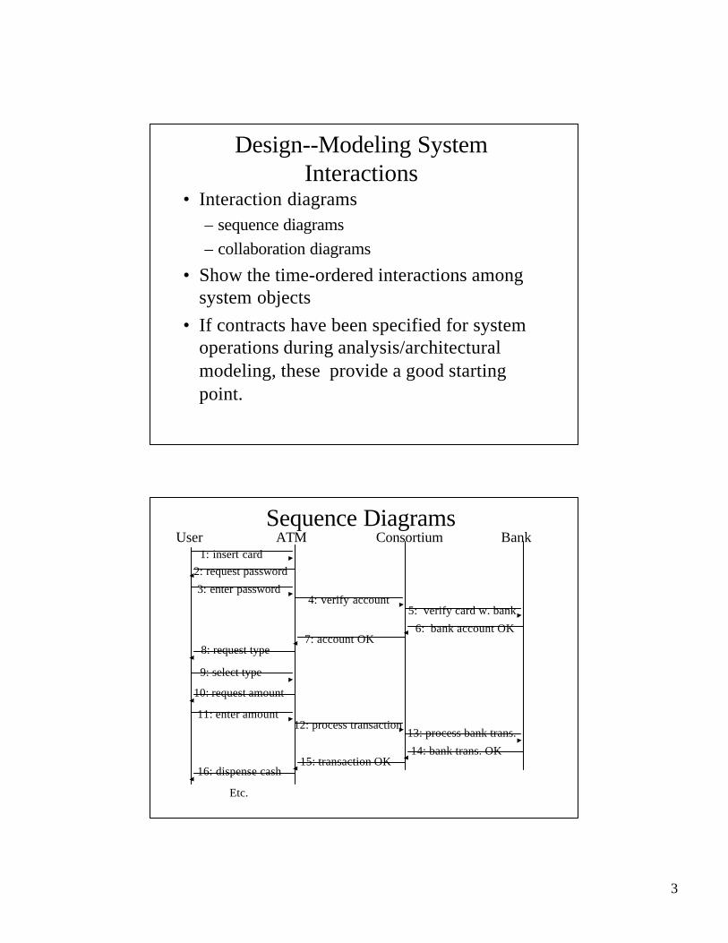
Design--Modeling SystemInteractions
• Interaction diagrams– sequence diagrams– collaboration diagrams
• Show the time-ordered interactions amongsystem objects
• If contracts have been specified for systemoperations during analysis/architecturalmodeling, these provide a good startingpoint.
Sequence DiagramsUser ATM Consortium Bank
1: insert card2: request password
3: enter password4: verify account
5: verify card w. bank
6: bank account OK7: account OK
8: request type
9: select type
10: request amount
11: enter amount12: process transaction
13: process bank trans.
14: bank trans. OK15: transaction OK
16: dispense cash
Etc.
4
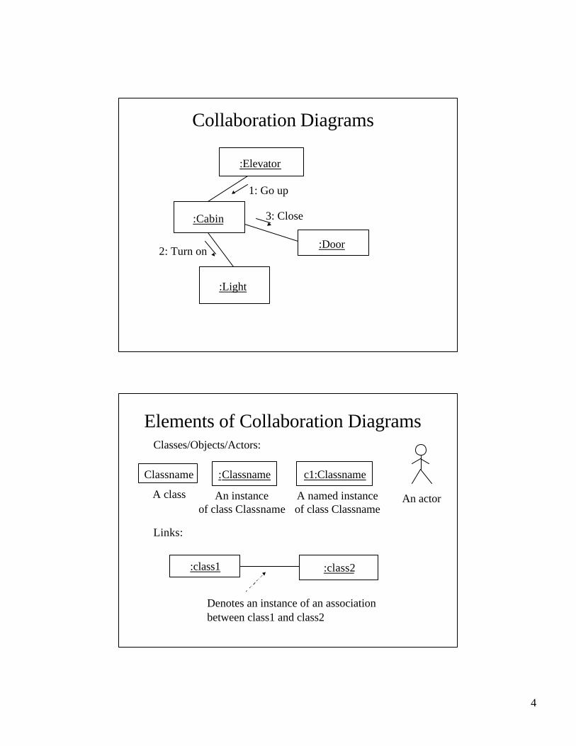
Collaboration Diagrams
:Elevator
:Cabin
:Light
:Door
1: Go up
2: Turn on
3: Close
Elements of Collaboration DiagramsClasses/Objects/Actors:
Classname
A class
:Classname
An instanceof class Classname
c1:Classname
A named instanceof class Classname
An actor
Links:
:class1 :class2
Denotes an instance of an association between class1 and class2
5
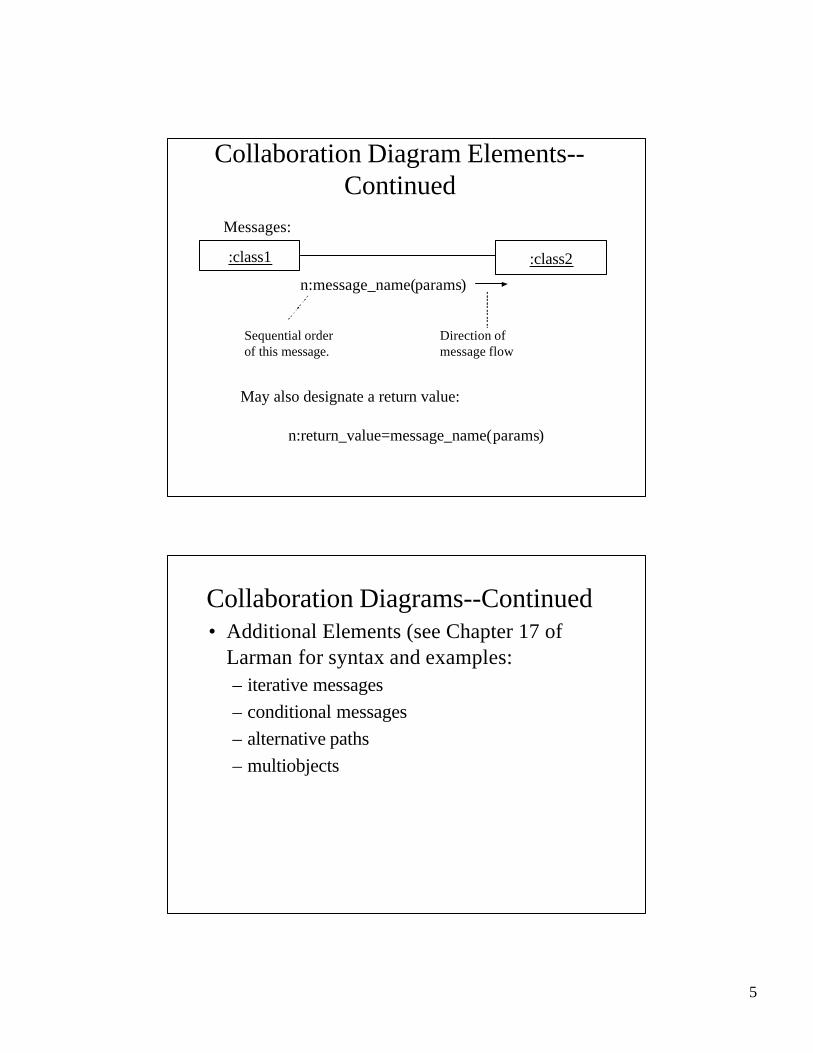
Collaboration Diagram Elements--Continued
Messages:
:class1 :class2
n:message_name(params)
Sequential orderof this message.
Direction ofmessage flow
May also designate a return value:
n:return_value=message_name(params)
Collaboration Diagrams--Continued• Additional Elements (see Chapter 17 of
Larman for syntax and examples:– iterative messages– conditional messages– alternative paths– multiobjects
6
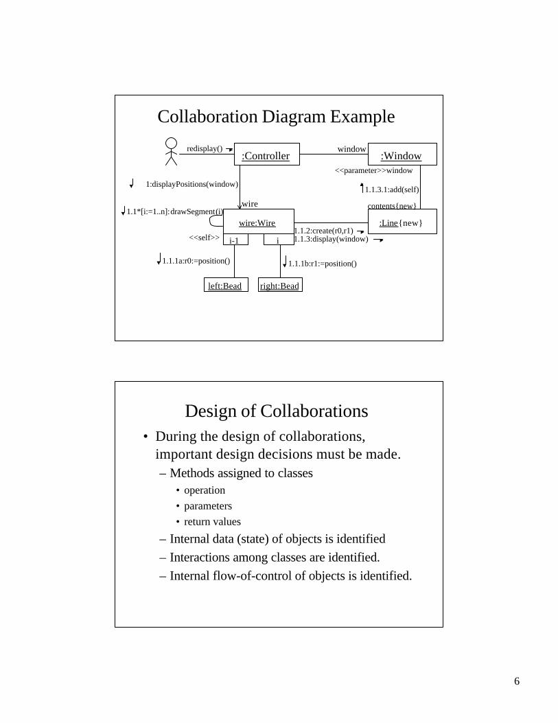
Collaboration Diagram Example
:Controller :Windowredisplay()
wire:Wire :Line{new}
i-1 i
left:Bead right:Bead
wire
window
1:displayPositions(window)
1.1*[i:=1..n]:drawSegment(i)
<<self>>
1.1.1a:r0:=position() 1.1.1b:r1:=position()
contents{new}
1.1.3.1:add(self)
<<parameter>>window
1.1.2:create(r0,r1)1.1.3:display(window)
Design of Collaborations• During the design of collaborations,
important design decisions must be made.– Methods assigned to classes
• operation• parameters• return values
– Internal data (state) of objects is identified– Interactions among classes are identified.– Internal flow-of-control of objects is identified.

7
Using Patterns to BuildCollaborations
• Design pattern: capture standard solutions(structures) that have evolved over time andhave been successfully applied to previousproblems.
• Why use patterns:– reuse– faster/more robust design– improved communication
Larman’s Design Patterns• GRASP--General Responsibility
Assignment Patterns– Expert– Creator– High Cohesion– Low Coupling– Controller– Polymorphism– Pure fabrication– Indirection– Don’t Talk to Strangers
Basic Patterns
AdvancedPatterns
8
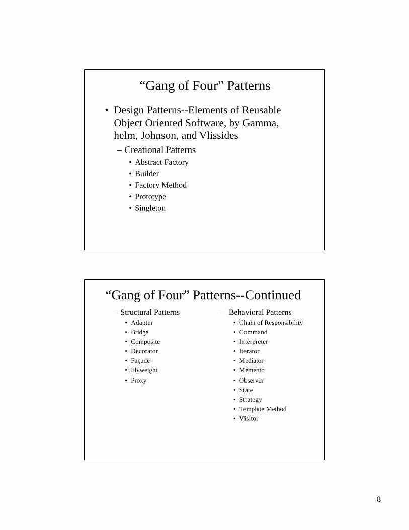
“Gang of Four” Patterns
• Design Patterns--Elements of ReusableObject Oriented Software, by Gamma,helm, Johnson, and Vlissides– Creational Patterns
• Abstract Factory• Builder• Factory Method• Prototype• Singleton
“Gang of Four” Patterns--Continued– Structural Patterns
• Adapter• Bridge• Composite• Decorator• Façade• Flyweight
• Proxy
– Behavioral Patterns• Chain of Responsibility• Command• Interpreter• Iterator• Mediator• Memento
• Observer• State• Strategy• Template Method• Visitor

9
Overview of the GRASP Patterns• Expert
– Assign a responsibility to the informationexpert--ie. The class that has the necessaryinformation to carry out the responsibility.
– Basic idea:• To what class or object should a given responsibility
be allocated--e.g. responsibility for authorizing anATM transaction?
• Identify the class that has the necessary information.• Assign a method to this class to carry out the
responsibility.
Expert Pattern ExampleATM Transaction Authorization: Who is responsible?
Consortium Bank
CashierStation
RemoteTransaction
CashCard
ATM
CashierTransaction
Cashier
Customer
AccountConsistsof
OwnsOwns
Entered on Enabledby
Holds Has
Has
AccessesConcerns
Employs
Owns Enteredby
Enteredon
Con-cerns
CardAuthorization
Issues
cash on handdispensed
name
nameaddress
name
balancecredit limit
type
date-timeamount
kind
date-timeamount
kind
passwordlimit
bank-codecard-code
serial number
Identifies
10
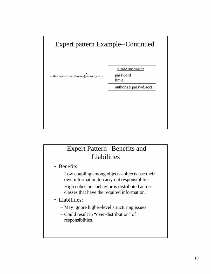
Expert pattern Example--Continued
:CardAuthorization
passwordlimit
authorize(passwd,acct)
authorization:=authorize(passwd,acct)
Expert Pattern--Benefits andLiabilities
• Benefits:– Low coupling among objects--objects use their
own information to carry out responsiblities– High cohesion--behavior is distributed across
classes that have the required information.
• Liabilities:– May ignore higher-level structuring issues– Could result in “over-distribution” of
responsiblities.

11
GRASP Patterns--Continued• Creator Pattern: Assign class B the
responsibility to create instances of class Aunder any of the following circumstances:– B aggregates objects of class A.– B contains objects of class A– B records instances of class A objects– B closely uses objects of class A.– B has initializing data for class A objects..
Creation Pattern ExampleWho should create CardAuthorizaton objects?
:Bank
name
CreateAuthorizaton()
CreateAuthorization(…)
1:Create (…)
:CardAuthorization{new}
12
Creator Pattern--Benefits andLiabilities
• Benefits:– Low Coupling--since creator already has
associations with created class
• Liabilities:– No real drawbacks--this is just common sense.– Choice of creator may not always be unique.
GRASP Patterns--Continued
• Low Coupling Pattern: Assignresponsibility so that coupling remains low.
• Coupling: degree of interaction amongobjects
• (Potential) advantages of low coupling:– reduced complexity– more opportunities for reuse– easier to modify
13
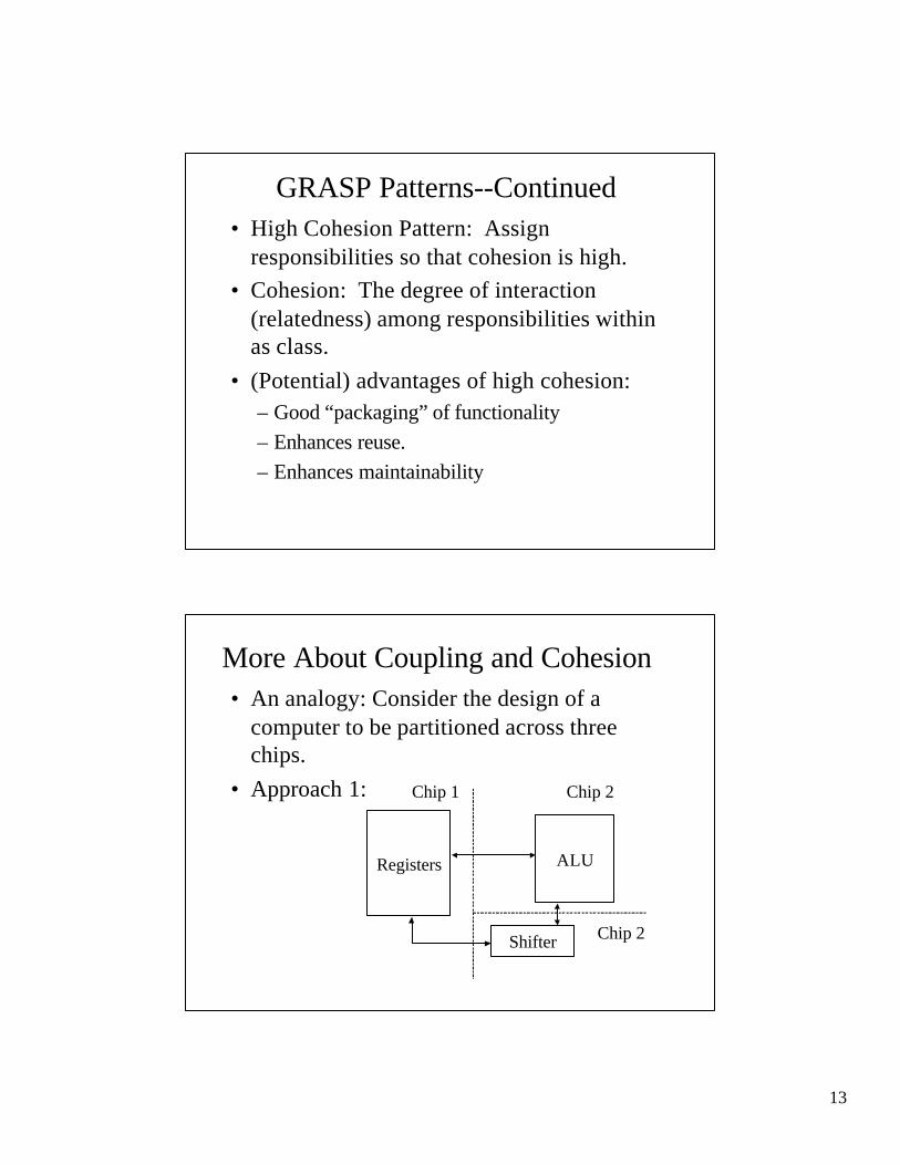
GRASP Patterns--Continued• High Cohesion Pattern: Assign
responsibilities so that cohesion is high.• Cohesion: The degree of interaction
(relatedness) among responsibilities withinas class.
• (Potential) advantages of high cohesion:– Good “packaging” of functionality– Enhances reuse.– Enhances maintainability
More About Coupling and Cohesion• An analogy: Consider the design of a
computer to be partitioned across threechips.
• Approach 1:
Registers ALU
Shifter
Chip 1 Chip 2
Chip 2
14
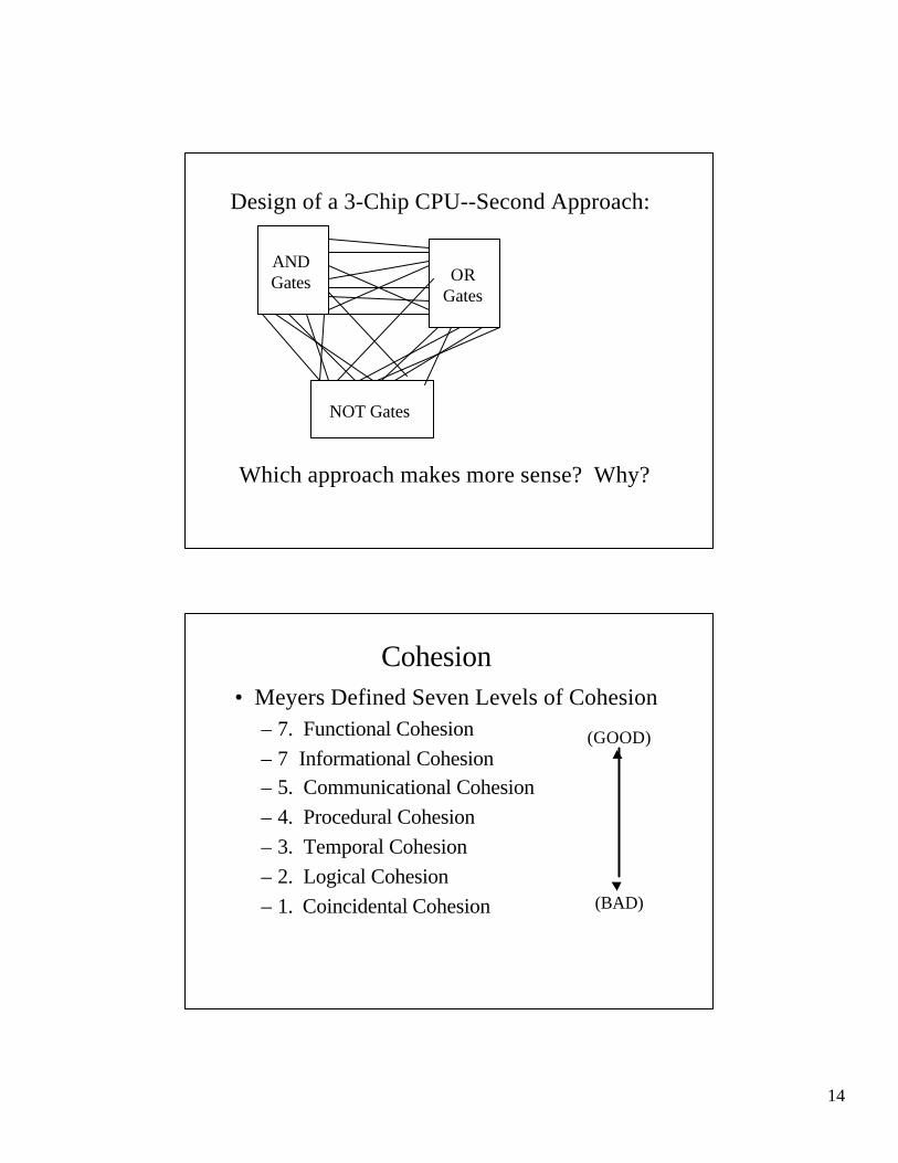
Design of a 3-Chip CPU--Second Approach:
ANDGates OR
Gates
NOT Gates
Which approach makes more sense? Why?
Cohesion• Meyers Defined Seven Levels of Cohesion
– 7. Functional Cohesion– 7 Informational Cohesion– 5. Communicational Cohesion– 4. Procedural Cohesion– 3. Temporal Cohesion– 2. Logical Cohesion– 1. Coincidental Cohesion
(GOOD)
(BAD)

15
Types of Cohesion• Coincidental
– module performs multiple, unrelated actions– This amounts to arbitrary modularization
• Logical– module performs a set of related actions, one of
which is selected by the calling module.– E.g , a module performing all input/output functions
for a complex system.
• Temporal– module performs a series of actions related in time.– E.g., module containing all system initialization
actions.
Types of Cohesion--Continued• Procedural
– module performs a set of weakly-connectedactions corresponding to the sequence of stepsin some operation
– E.g., all of the operations involved in an ATMtransaction
• Communicational– module performs a sequence of steps, related to
some operation, which operate on the samedata.
– E.g., update a database, record update to audittrail, print the update.

16
Types of Cohesion--Continued• Informational
– module performs a set of independent actions,all of which operate on the same data strucure
– E.g., implementation of an Abstract Data Type
• Functional Cohesion– module performs one coherent action or
achieves a single objective– E.g., “calculate sales commision.”
A Cohesion ExampleCompute averagedaily temperatures
at various sites.
Initialize sumsand
open files
Create newtemperature
record
Store temperature
record
Close files andprint averagetemperatures
Read in site,time, and
temperature
Store record for specific
site
Edit site, time,or temperature
field

17
Coupling
• Five levels of coupling:– 5. Data Coupling– 4. Stamp Coupling– 3. Control Coupling– 2. Common Coupling
(GOOD)
(BAD)
Types of Coupling
• Content Coupling– one module directly references the content of
the other.– E.g. module A branches to a local label of
module B.
• Common Coupling– two modules share access to the same global
data– E.g., modules use global variables to pass
arguments

18
Types of Coupling--Continued• Control Coupling
– one module explicitly controls the logic ofanother
– E.g. a control switch is passed as an argument
• Stamp Coupling– a data structure is passed as an argument but
called module only operates on some individualcomponents of the data structure
– E.g., an employee record is passed to a modulewhich only needs the salary field.
Data Coupling• Data Coupling
– all data exchanged by modules arehomogeneous data items.
– I.e., either simple data values or data structuresin which all elements are used by the calledmodule.

19
Coupling Examplep
qs
u
r
t
Aircrafttype
Statusflag
List of parts
Function code
DatabasePart number
Manu-facturer
Partnumber Part
name
List of parts
update
updateupate
GRASP Patterns--Continued• Controller Pattern
– Assign responsibility for handling a systemevent to one of the following controller classes:
• One representing the overall “system”, business, ororganization
– façade controller
• One that represents an active real-world entity thatmight be responsible for the task
– role controller
• One that represents an artificial hander of all systemevents associated with some collaboration
– use-case controller

20
Controller Pattern--Continued• System event--generated by external actor
– associated with system operations.– E.g. user selecting a function on ATM screen.
• Controller--object responsible for handlinga system event.
• Possible choices for ATM transaction– System or ATM--façade controller– Teller--role controller– ATMTransactonHandler--use-case controller
Controller Classes--Which Type to Use:• Façade controller
– places all system event handling in a single class– may become too complex and incohesive if the number
and range of system events is high.
• Role controller– attempts to mimic behavior of a human agent– may suffer from imperfect or awkward analogy
• Use-case controller– allocates controller responsibility on a per-collaboration
basis– best choice if system has many events spread across
several operations.
21
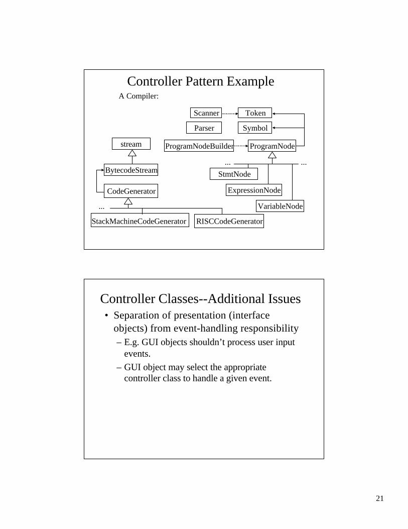
Controller Pattern ExampleA Compiler:
StackMachineCodeGenerator
stream
BytecodeStream
CodeGenerator
RISCCodeGenerator
...
Scanner Token
Parser Symbol
ProgramNodeBuilder ProgramNode
StmtNode
ExpressionNode
VariableNode
... ...
Controller Classes--Additional Issues• Separation of presentation (interface
objects) from event-handling responsibility– E.g. GUI objects shouldn’t process user input
events.– GUI object may select the appropriate
controller class to handle a given event.