intelligent wellhead systems invision system€¦ · intelligent wellhead systems – invision...
TRANSCRIPT

Intelligent Wellhead Systems – inVision System
Saudi Aramco: Site #12 – HRDH -1303 Coiled Tubing Intervention
January 2020
Abstract:
Intelligent Wellhead Systems supplied a 5-1/8” 10M inVision Critical Well Intervention System to Saudi Arabia. On January
10th, 2020 the system was mobilised to Site #12 – HRDH-1303 as a part of a High Pressure Coiled Tubing and Slickline fishing
operation to recover 3-1/8” guns, 9,775’ of 9/32” alloy electric line, PEAK cable cutter and drop bar. The inVision job scope
consisted of Coiled Tubing fishing of the near surface 300’ of electric line cable. This was successfully completed over seven
days using Halliburton Coiled Tubing Unit CTU-13. The inVision System was successfully integrated with the Coiled Tubing
Unit and identified the connector location, variations in BHA and Coiled Tubing diameters, provided an extra level of safety
identifying false bump-ups and preventing well control issues associated with staging the fish out of the well.
Leaders in Critical Well Intervention Technology

Developers of the Canadian Headquarters 7633 - 57 St, SE Calgary, AB., Canada T2C 5M2 1-866-776-6578
US Headquarters 511 16th St, Suite 500 Denver, Colorado, USA 80202
Contents 1 Introduction ........................................................................................................................................... 2
2 System Equipment Overview ................................................................................................................ 3
3 Operations ............................................................................................................................................. 4
3.1 Mobilization: Friday, January 10th ................................................................................................ 5
3.2 Rig-Up: Saturday, January 11th to Sunday, January 12th .............................................................. 5
3.3 Operations Summary ..................................................................................................................... 9
3.3.1 January 13th - Coiled Tubing Run #1, 2, 3, 4 .......................................................................... 9
3.3.2 January 14th - Coiled Tubing Run #5 ...................................................................................... 9
3.3.3 January 15th – Coiled Tubing Run #6, 7, 8 ............................................................................. 9
3.3.4 January 16th – Coiled Tubing # 9, 10, 11 .............................................................................. 10
3.4 Rig-Down: Thursday, January 16th .............................................................................................. 13
4 Conclusion ........................................................................................................................................... 14
5 APPENDIX A ......................................................................................................................................... 17

Developers of the Canadian Headquarters 7633 - 57 St, SE Calgary, AB., Canada T2C 5M2 1-866-776-6578
US Headquarters 511 16th St, Suite 500 Denver, Colorado, USA 80202
1 Introduction Intelligent Wellhead Systems (“IWS”) inVision System is a technology that was developed to improve
well intervention decision making processes. This is accomplished by enabling the operator to visualize
size and location of BHA components and tubing while being tripped through the pressurized BOP stack.
The system generates a 2D image of ferrous alloy tool string components, indicating tool diameter
profiles and lateral tool location. This is achieved by combining outputs from proprietary magnetic
sensors placed radially around a specially engineered spacer spool that is installed in the PCE stack. The
system is completely non-intrusive, introducing no additional leak paths and can be installed at any point
in the PCE Stack.
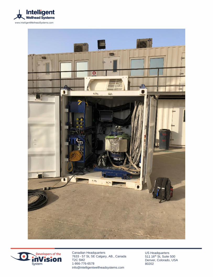
The inVision System is transported in a 6’L x 6’W x 8’H container and comes equipped with fork pockets
and a 4-Leg Lifting sling for ease of transportation and equipment positioning on site. Systems designed
for KSA come with additional cooling equipment to ensure the control system is kept with-in operating
temperature.
The system shown in Figure 1.) had been previously shipped to complete the intervention operation for
Aramco TTR in April 2019. The TTR file #TR-2018-0051 was finalised in October 2019. The system was
staged out of the Haliburton UDH Base in a collaborative effort involving IWS and Halliburton.
Figure 1. HAL UDH BASE Yard 4: IWS FS03 prior to mobilising to Site #12 - HRDH-1303

Developers of the Canadian Headquarters 7633 - 57 St, SE Calgary, AB., Canada T2C 5M2 1-866-776-6578
US Headquarters 511 16th St, Suite 500 Denver, Colorado, USA 80202
2 System Equipment Overview The inVision System used in this TTR consists of a 5-1/8” 10M inVision spool with a 4-1/16” 10M cross-
over. The pressure containing equipment is API 6A monogramed and all wetted surfaces are Inconel 625
lined for ultra high H2S and CO2 service. Full system specification and system inventory is outlined in

Developers of the Canadian Headquarters 7633 - 57 St, SE Calgary, AB., Canada T2C 5M2 1-866-776-6578
US Headquarters 511 16th St, Suite 500 Denver, Colorado, USA 80202
APPENDIX A.
Figure 2.) outlines the 5-1/8” 10M inVision spool and cross over dimensions. The system weighs 780 lbs
and is 26” in height. The spool features a robust stainless-steel guard designed to protect the magnetic
sensor array and electronic components of the system against general oilfield use and direct sunlight.
Figure 2. inVision Spool Schematic
Interaction with the system is achieved through various interfaces including a wired zone rated HMI at
the wellhead controls, as well as two zone rated wireless tablet interfaces and two general zone wireless
tablet interfaces. Figure 3.) demonstrates what the inVision operator Interface looks like as a coiled
tubing BHA is run in hole. The diameter being measured is displayed to the left of the image. A visual

Developers of the Canadian Headquarters 7633 - 57 St, SE Calgary, AB., Canada T2C 5M2 1-866-776-6578
US Headquarters 511 16th St, Suite 500 Denver, Colorado, USA 80202
indication of lateral location and detected OD is displayed in the center and a side profile view of the
detected diameters is displayed to the right.
Figure 3. inVision Operator Interface
Critical spares and multiple system redundancies are included with each unit and all equipment is
transported in the container. See

Developers of the Canadian Headquarters 7633 - 57 St, SE Calgary, AB., Canada T2C 5M2 1-866-776-6578
US Headquarters 511 16th St, Suite 500 Denver, Colorado, USA 80202
APPENDIX A) for complete system specification and system inventories.
3 Operations The following section details the inVision System mobilization, Rig-Up/Rig-Down requirements and
system performance through-out the intervention. Additionally, the systems log files have been retained
should further analysis be required. The system log files are timestamped and sampled at a rate of 1 Hz.
The information contained in the log files include diameter, lateral location and bore temperature. as
detected at the point of installation of the inVision spool. The log files enable the viewer to replay the
job in real time or at an accelerated rate and view the information in both graphical form and HMI view.
The inVision System detected the coiled tubing BHA and coiled tubing string within OEM specification.
The system provided audible and visual alerts when detecting the BHA and when it cleared the inVision
spool at the end of the run. The pneumatic visual indicator system performed within specification and
provided an additional safety alert as to the presence of coiled tubing in hole, this indicator was placed
on the crown valve.
3.1 Mobilization: Friday, January 10th
The inVision System was mobilized with a Halliburton coiled tubing unit CTU-13 from Haliburton UDH
Base Yard 4 to Site #12 approximately 2 hours 20 minutes. The system was transported on a flat deck
truck and was loaded and unloaded at both ends using a fork lift.
3.2 Rig-Up: Saturday, January 11th to Sunday, January 12th
The inVision Container was positioned in front of the coiled tubing unit. 110VAC power was supplied by
the coiled tubing generator and air was sourced from the coiled tubing unit’s onboard compressor.
A zone rated HMI was located along the walk path from the coiled tubing unit to the wellhead and
behind the slick line truck, clearly visible to personnel approaching the wellhead. A tablet interface was
placed in the coiled tubing unit as shown in Figure 4.)

Developers of the Canadian Headquarters 7633 - 57 St, SE Calgary, AB., Canada T2C 5M2 1-866-776-6578
US Headquarters 511 16th St, Suite 500 Denver, Colorado, USA 80202
Figure 4. inVision Interface installed inside Coiled Tubing Unit
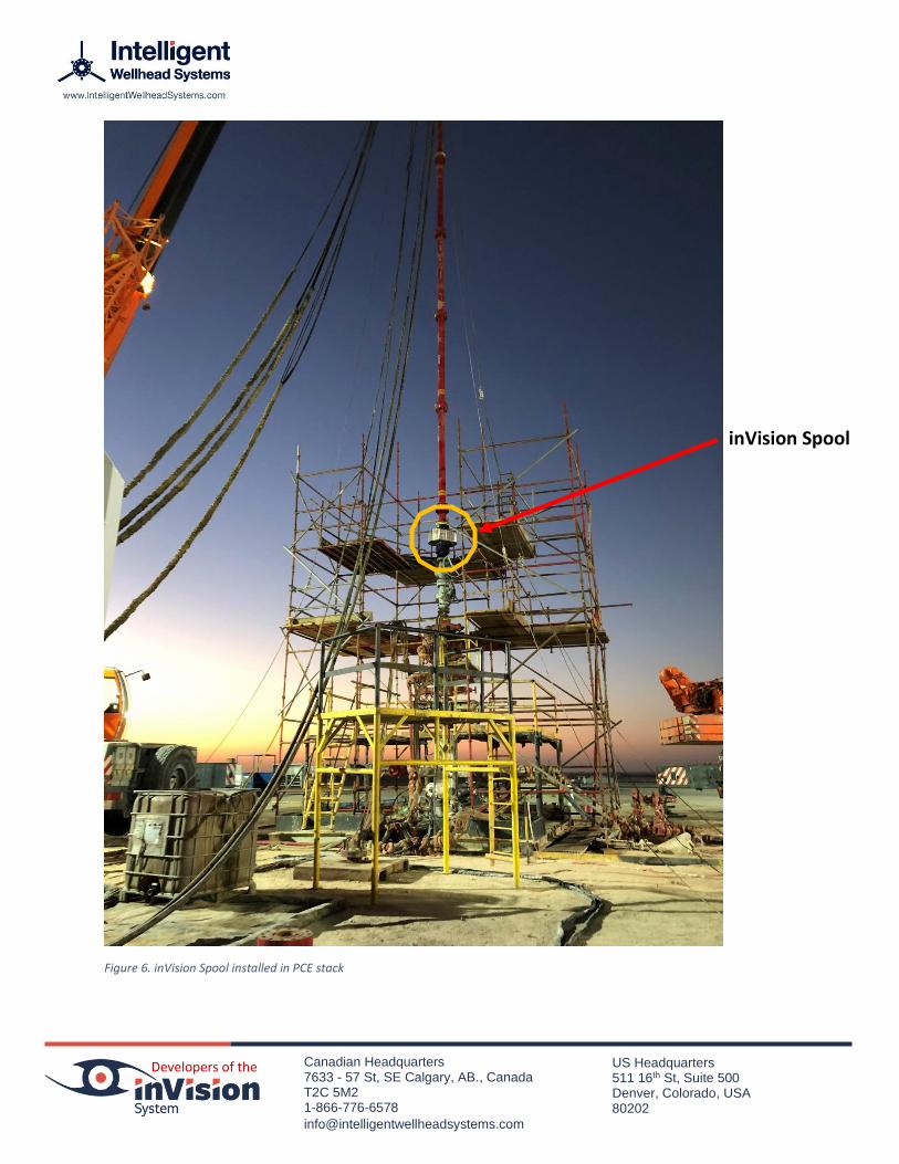
Error! Reference source not found..) Shows the inVision spool as it was installed forming part of the
riser assembly above the two 4-1/16” gate valves and the coiled tubing QUAD BOP. See Figure 6.) for
installation photograph and Figure 7.) for installation diagram. It is important to note that the inVision
spool can be installed at any point throughout the PCE stack as considered most useful for a given
intervention.

Developers of the Canadian Headquarters 7633 - 57 St, SE Calgary, AB., Canada T2C 5M2 1-866-776-6578
US Headquarters 511 16th St, Suite 500 Denver, Colorado, USA 80202
Figure 5. inVision Spool Installation
inVision Spool
Developers of the Canadian Headquarters 7633 - 57 St, SE Calgary, AB., Canada T2C 5M2 1-866-776-6578
US Headquarters 511 16th St, Suite 500 Denver, Colorado, USA 80202
Figure 6. inVision Spool installed in PCE stack
inVision Spool

Developers of the Canadian Headquarters 7633 - 57 St, SE Calgary, AB., Canada T2C 5M2 1-866-776-6578
US Headquarters 511 16th St, Suite 500 Denver, Colorado, USA 80202
Figure 7. inVision Spool Installation Diagram
Coiled Tubing Injector
Riser
inVision Spool
BOP Assembly
Dual Gate Valve Assembly
Wellhead

Developers of the Canadian Headquarters 7633 - 57 St, SE Calgary, AB., Canada T2C 5M2 1-866-776-6578
US Headquarters 511 16th St, Suite 500 Denver, Colorado, USA 80202
3.3 Operations Summary
The following section contains a summary of the fishing operations highlighting critical points of interest
as the coiled tubing BHA was run in and out of hole at surface. The fishing operation was completed
using a combination of coiled tubing and slickline. Slickline was utilized to locate fish top and coiled
tubing was used to extract the wireline fish in sections using the expandable wire grab fishing tool.
3.3.1 January 13th - Coiled Tubing Run #1, 2, 3, 4
02:15 AM - Coiled tubing completed its first run. Fish top was located at 404 ft. and 21 ft. of wireline was retrieved from the well. The retrieved wireline was deemed to be in good condition with minimal signs of corrosion or mechanical damage. 11:05 AM – Slick line operations were installed located fish top at 426 ft. 12:20 PM – Coiled tubing was installed and ran in hole to 505 ft. retrieving 9 ft. of wireline. 15:00 PM – Slick line operations commenced and located fish top at 429 ft. 16:15 PM – Coiled tubing operations commenced to run in hole locating fish top at 435 ft. and began latching on to fish. Coiled tubing operations were unsuccessful in recovering any wireline on this run. 18:00 PM – Coiled tubing operations commenced to run in hole. Issues were encountered whilst moving the BHA through the wellhead. It was determined that the fishing tool had made contact with the Master Valve which resulted in some permanent bending of the actuator arms of the fishing tool. The backup BHA was run and failed due to a stuck actuating arm. Coiled tubing operations were put on standby until new BHA’s could be mobilized to site from Weatherford Dammam base.
3.3.2 January 14th - Coiled Tubing Run #5
11:45 AM – Slickline operations were installed on the well and run in hole to compress the fish
top down hole as far as possible. The intent of this was to improve the amount of wireline that
could be retrieved by coiled tubing while waiting for replacement BHA’s to arrive.
16:30 PM – Replacement coiled tubing BHA arrived and on site testing of the new components
commenced. One of the two replacement BHA’s failed testing.
18:30 PM – Coiled tubing commenced fishing operations again, retrieving 45 ft. of wireline.
3.3.3 January 15th – Coiled Tubing Run #6, 7, 8
07:45 AM – Slickline was installed on the well and began to run in hole to compress the
remaining wireline. Slickline reached a maximum depth of 361 ft.
11:50 AM – Coiled tubing was installed and run in hole to a depth of 375 ft. retrieving 52 ft. of
wireline.
14:45 PM – Slickline was installed on the well to compress the wireline fish and reached a
maximum depth of 384 ft.
17:05 PM – Coiled tubing was installed on the well and reached a depth of 396 ft. retrieving 52
ft. of wireline.
Developers of the Canadian Headquarters 7633 - 57 St, SE Calgary, AB., Canada T2C 5M2 1-866-776-6578
US Headquarters 511 16th St, Suite 500 Denver, Colorado, USA 80202
21:15 PM: Slickline was installed on the well and ran in hole compressing wireline fish to a
maximum depth of 372 ft.
22:54 PM: Coiled tubing was installed on the well and successfully retrieved 56 ft. of wireline.
3.3.4 January 16th – Coiled Tubing # 9, 10, 11
01:45 AM – Slickline was installed on the well and ran in hole compressing wireline fish to a
maximum depth of 382 ft.
02:50 AM – Coiled tubing was installed on the well and successfully retrieved 42 ft. of wireline.
04:15 AM – Slickline was installed on well and compressed wireline fish to a maximum depth of
360 ft.
06:35 AM – Coiled tubing was installed on the well and failed to retrieve any wireline fish.
08:15 AM – Slickline was installed on the well and compressed the wireline fish to a depth of 361
ft.
11:30 AM – Coiled tubing was installed on the well and retrieved 41 ft. of wireline.
12:30 PM – Decision made to release services.
14:30 PM – Coiled tubing commenced rig out operations.
20:00 PM – IWS inVision System secured for demobilization to Halliburton Yard 4 UDH staging
yard.
One of the key objectives of inVision was to identify the CT connector as it entered the riser section.
This allowed the CT operator to stop the coil in exactly the correct location in order to cut the retrieved
cable.
The system performed within specification through out the job and detected variations in diameter
sufficient to clearly identify BHA components. Audible and visual alerts were issued by the system when
the BHA was detected while pulling out of the hole and again when the BHA cleared the inVision spool at
surface. Video play back files are included with the supporting material for this document.
The inVision System records all data in system log files. These log files are stored on the primary control
box and on each HMI connected to the system. The log files are stored in a secure proprietary format
and can be viewed using the inVision Log File viewer. A brief analysis was performed on these log files to
identify the BHA as it entered and exited the inVision spool.

Developers of the Canadian Headquarters 7633 - 57 St, SE Calgary, AB., Canada T2C 5M2 1-866-776-6578
US Headquarters 511 16th St, Suite 500 Denver, Colorado, USA 80202
Figure 8.) depicts the BHA as it was run in hole using the inVision Log File viewer. The inVision log files
contain detailed records of the inVision Systems measurements and can be played back post job for
analysis.
Figure 8. 01-12-2020 HRDH 1303 First run Coiled Tubing – Run in hole to 404 ft.

Developers of the Canadian Headquarters 7633 - 57 St, SE Calgary, AB., Canada T2C 5M2 1-866-776-6578
US Headquarters 511 16th St, Suite 500 Denver, Colorado, USA 80202
Figure 9.) References the Halliburton fishing BHA utilized on this intervention. The BHA included an
Expandable Wire Grab, Fixed Centralizer, MHA and CT External Connector to 2” coiled tubing. It is
important to note that the listed OD for each tool is the maximum OD. As can be seen in the video files
supporting this document the measured OD fluctuates in accordance with the BHA profile.
Figure 9. Halliburton BHA Schematic

Developers of the Canadian Headquarters 7633 - 57 St, SE Calgary, AB., Canada T2C 5M2 1-866-776-6578
US Headquarters 511 16th St, Suite 500 Denver, Colorado, USA 80202
Figure 10.) depicts the BHA as it was pulled out of hole using the inVision Log File viewer. The system log
files contain lateral location information, detected diameters and well bore temperatures. Total job
duration and other important tool-string information can be obtained from the log files for future
reference as required.
Figure 10. 01-12-2020 HRDH 1303 First run Coiled Tubing – Retrieved 21 ft. CRA Wireline
3.4 Rig-Down: Thursday, January 16th
The inVision System rig-down was performed off critical path time and took a total of 45 minutes to
prepare for transport. The inVision spool was lowered to ground level as part of the coiled tubing riser
and injector assembly. The inVision spool was disconnected at ground level and stored in the transport
container using the site forklift.

Developers of the Canadian Headquarters 7633 - 57 St, SE Calgary, AB., Canada T2C 5M2 1-866-776-6578
US Headquarters 511 16th St, Suite 500 Denver, Colorado, USA 80202
4 Conclusion Throughout the job the inVision System added value by consistently identifying coiled tubing diameters
as well as in hole / out of hole status and communicating this information at critical points on site through
out the operation. This information was displayed in the coiled tubing cab, primary access routes to the
wellhead and via the visual wellhead indicator attached to the crown valve on the wellhead. The interface
can also be displayed on wireless tablets which can be placed anywhere on site within range of the systems
WiFi network. The user interface was found to be intuitive and was easily interpreted by the coiled tubing
crew.
The coiled tubing crew was intrigued to witness the behavior of the coiled tubing inside the pressurized
zone of the PCE stack. The inVision System enabled the coiled tubing operators to correlate the impact of
various actions on the coiled tubing injector and other surface equipment on the coiled tubing, inside the
PCE stack. For example, while RIH the coiled tubing skipped on the reel, the resulting jolt could be seen
affecting the coiled tubing inside the PCE stack using the systems lateral location features.
It was noted that coiled tubing fatigue and wear could be reduced by using the system to adjust crane
boom angles and guy-line tensions to centralize the coiled tubing within the well bore and prevent rubbing
on the internals of the wellhead and other surface equipment.
Further advantages noted by the coiled tubing crew were often a result of past experiences where the
benefits of the system could have been realized. Some of these issues included; surface obstructions while
running in hole, false tag outs, failed depth counters, scale build up, parted tubing, slim-hole BHA’s, etc.
Many of the benefits of the system were made possible by improving operator awareness and
understanding of the behaviour of their coiled tubing inside the PCE stack, this is a data point that has
been omitted from operations until now.
On this fishing job for well HRDH-1303 the primary benefit of the inVision System was the ability to
confidently identify when the coiled tubing BHA was passing through the wellhead and had been
completely removed from the wellbore, thus, enabling the safe closing of the wellhead valves. During
fishing operations many complications can arise from misinformation, guesswork or assumptions around
the interpretation of various equipment sensors. Typical fishing procedure rely on the depth counter to
indicate when the BHA may be nearing surface; then the weight indicator is used to identify when the
coiled tubing connector has made physical contact with the stuffing box. This method becomes
problematic and can result in significant delays, equipment damage or critical well control incidence when
the coiled tubing depth counter fails, a false tag out occurs or if the coiled tubing is parted. New technology
like the inVision System now enables the coiled tubing and wireline operators to clearly identify exactly
where key BHA and toolstring components are within the PCE stack using reliable non-intrusive sensing
technology. As the inVision System becomes widespread SOP’s and new procedures are being written to
take advantage of this technology and complete jobs in ways that have not ben previously possible.
The entire Intelligent Wellhead Systems team would like to thank Halliburton Energy Services, the crews
of CTU13 and Saudi Aramco for the continuing opportunity to demonstrate value with the inVision Critical
Well Intervention System and looks forward to future collaboration.
Developers of the Canadian Headquarters 7633 - 57 St, SE Calgary, AB., Canada T2C 5M2 1-866-776-6578
US Headquarters 511 16th St, Suite 500 Denver, Colorado, USA 80202
InVision Application: Critical well operations
The system displays an image of the cross section of the Pressure Control Equipment (WHE) stack at the
installed location of the inVision Spool.
The following data is clearly displayed on operator and company supervisor screens:
• Tool and tubing O.D. • Lateral location of the tool, coiled tubing or wireline • Tool O.D. profile (visualization of the tool O.D. versus time as the BHA moves up
or down) Benefits:
• Reduce exposure to risk, particularly on complex operations such as fishing, milling, slim BHA, high pressure and H2S
• Increase well control and decision-making capability through increased information
• Understand exactly what component is moving through the wellhead • Immediately identify surface issues when running in or out of well • Engineered hazard mitigation • Prevent fishing operations • Prevent improper actuation of BOP and shear valve • Prevent hydrocarbon release from stripper • Remove personnel from Red Zones • Provides Verification versus Educated guessing • Enable faster Coiled Tubing / Wireline Intervention • Enable modification of specific Standard Operating Procedures (SOP) reducing
NPT • Enable efficient, accurate communication onsite between services and company
supervisor • Correlate depth counters using inVision
• Avoid HSE loss time incidents • Peace of mind for all • Detects diameter of wireline, tubulars and downhole tools through the inVision spool in real
time • Substantial increase in efficiency, safety and visibility of daily operations • Adding inVision technology to the operation safely increases the speed of live well intervention
operations. • Numerous well control risks are removed. • Reduced operator stress levels when performing certain critical tasks within a live well
intervention. • The tool adds a layer of protection in your risk matrix. • Data reports provided by the system gives clear, accurate visibility into daily operations at the
wellhead. •

Developers of the Canadian Headquarters 7633 - 57 St, SE Calgary, AB., Canada T2C 5M2 1-866-776-6578
US Headquarters 511 16th St, Suite 500 Denver, Colorado, USA 80202
Coiled Tubing Operation Challenges that are addressed or avoided by inVision:
• Depth Counter Inaccuracy
• Perform Bump-Up
• Exposure to Human Error
• Pull through Stripper/Injector with slim BHA
• Personnel in Red Zone

Developers of the Canadian Headquarters 7633 - 57 St, SE Calgary, AB., Canada T2C 5M2 1-866-776-6578
US Headquarters 511 16th St, Suite 500 Denver, Colorado, USA 80202
5 APPENDIX A This section contains system specification and system inventories.
Developers of the Canadian Headquarters 7633 - 57 St, SE Calgary, AB., Canada T2C 5M2 1-866-776-6578
US Headquarters 511 16th St, Suite 500 Denver, Colorado, USA 80202

Developers of the Canadian Headquarters 7633 - 57 St, SE Calgary, AB., Canada T2C 5M2 1-866-776-6578
US Headquarters 511 16th St, Suite 500 Denver, Colorado, USA 80202

Developers of the Canadian Headquarters 7633 - 57 St, SE Calgary, AB., Canada T2C 5M2 1-866-776-6578
US Headquarters 511 16th St, Suite 500 Denver, Colorado, USA 80202