intelligent wan configuration files guide (cvd) … cost while maintaining a high level of ......
TRANSCRIPT

s CisCo Validated design
Intelligent WAN Configuration Files Guide
september 2017
Table of Contents
Cisco Validated Design
Table of ContentsIntroduction ..................................................................................................................................... 1
Product List ................................................................................................................................... 10
IWAN Hybrid Design Model for EIGRP—WAN Aggregation .............................................................. 11
Configuration Files ....................................................................................................................................................... 13
IWAN Hybrid Design Model for EIGRP—Remote Sites ..................................................................... 14
Configuration Files......................................................................................................................................................... 15
IWAN Hybrid Design Model with MNH and MTT for EIGRP—WAN Aggregation ............................... 16
Configuration Files ....................................................................................................................................................... 18
IWAN Hybrid Design Model with MNH and MTT for EIGRP—Remote Sites ...................................... 19
Configuration Files......................................................................................................................................................... 20
IWAN Dual Hybrid with PLR and MTT Design Model for BGP—WAN Aggregation with DCI ............. 21
Configuration Files......................................................................................................................................................... 23
IWAN Dual Hybrid with PLR and MTT Design Model for BGP—WAN Aggregation without DCI ........ 24
Configuration Files......................................................................................................................................................... 26
IWAN Dual Hybrid with PLR and MTT Design Model for BGP—Remote Sites ................................... 27
Configuration Files......................................................................................................................................................... 28
IWAN Dual Hybrid with PLR and Multi-VRF Design Model for BGP—WAN Aggregation ................... 29
Configuration Files......................................................................................................................................................... 32
IWAN Dual Hybrid with PLR and Multi-VRF Design Model for BGP—Remote Sites .......................... 33
Configuration Files......................................................................................................................................................... 34
Appendix A: Changes .................................................................................................................... 35

page 1Cisco Validated Design
Introduction
IntroductionThe Cisco Intelligent WAN (IWAN) solution provides design and implementation guidance for organizations looking to deploy wide area network (WAN) transport with a transport-independent design (TID), intelligent path control, application optimization, and secure encrypted communications between branch locations while reducing the operating cost of the WAN. IWAN takes full advantage of cost-effective transport services in order to increase bandwidth capacity without compromising performance, reliability, or security of collaboration or cloud-based ap-plications.
This document provides the available configuration files for the products used in the Intelligent WAN Deployment Guide and the Intelligent WAN advanced series of guides.
The advanced guides are as follows:
• IWAN High Availability and Scalability Deployment Guide
• IWAN Multiple Data Center Deployment Guide
• IWAN Multiple Transports Deployment Guide
• IWAN Multiple VRF Deployment Guide
• IWAN Public Key Infrastructure Deployment Guide
• IWAN NetFlow Monitoring Deployment Guide
• IWAN Remote Site 4G LTE Deployment Guide
This guide is a companion document to the deployment guides, serving as a reference for engineers who are evaluating or deploying the IWAN solution.
This guide describes two base IWAN design models and three advanced IWAN design models.
The first design model is the IWAN Hybrid, which uses MPLS paired with Internet as WAN transports. In this design model, the MPLS WAN can provide more bandwidth for the critical classes of services needed for key ap-plications and can provide SLA guarantees for these applications.
The second design model is the IWAN Dual Internet, which uses a pair of Internet service providers to further reduce cost while maintaining a high level of resiliency for the WAN.

page 2Cisco Validated Design
Introduction
Figure 1 IWAN hybrid model—WAN aggregation site overview
1248
F
WAN DistributionLayer
Core Layer
DMVPN 2DMVPN 1
Internet Edge
INET
Hub BorderRouters
Hub MasterController
DMVPN HubRouters
MPLS
Figure 2 IWAN dual Internet model—WAN aggregation site overview
12
40
F
Hub MasterController
WAN DistributionLayer
Core Layer
DMVPN 12DMVPN 11
Internet EdgeHub Border
RoutersDMVPN HubRouters
INET
ISP A / ISP B

page 3Cisco Validated Design
Introduction
Figure 3 IWAN—Remote-site overview
1241
F
BranchBorderRouter
Branch MasterController/
Branch BorderRouter
Branch Master Controller/
Branch BorderRouter
Single Router Location Dual Router Location
The first advanced design builds on previous design models by adding hub borders routers for horizontal scaling at a single data center. This design also has an option to add a second hub master controller (MC) at a single data center for high availability.
Figure 4 IWAN dual Internet Model—Hub MC high availability
WAN DistributionLayer
Core Layer
DMVPN 12
23
07
F
DMVPN 11
Internet EdgeHub Border
Routers (BR)
INET
ISP A / ISP BINET1 INET2
Hub MasterController (MC)Lo1: 10.6.32.252/32
Hub MasterController (MC-HA)Lo1: 10.6.32.252/31
page 4Cisco Validated Design
Introduction
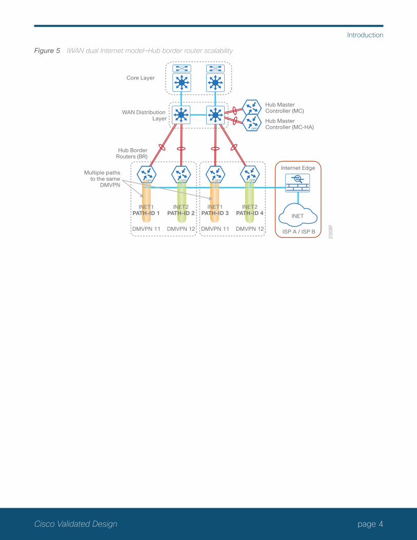
Figure 5 IWAN dual Internet model—Hub border router scalability
DMVPN 12
23
08
F
DMVPN 11
WAN Distribution Layer
Hub Master Controller (MC)
Multiple pathsto the same
DMVPN
Hub MasterController (MC-HA)
DMVPN 12DMVPN 11
Hub BorderRouters (BR)
Core Layer
Internet Edge
ISP A / ISP B
INET1PATH-ID 1
INET1PATH-ID 3
INET2PATH-ID 4 INET
INET2PATH-ID 2

page 5Cisco Validated Design
Introduction
The second advanced design builds on previous design models with data center redundancy. The multi-data center or the transit site support feature enables organizations to scale their network infrastructure and load-balance the traffic when required. The first version of this advanced design uses a data center interconnect (DCI) link between the hub and transit sites.
Figure 6 IWAN hybrid model—Second data center as a transit site with DCI
DMVPN 2
23
09
FDMVPN 1
Hub MCPOP-ID 0
10.4.0.0/1610.6.0.0/16
Hub Site
MPLS1PATH-ID 1
INET1PATH-ID 2
Hub BRs
DMVPN 2DMVPN 1
Transit MCPOP-ID 1
10.4.0.0/1610.8.0.0/16
Transit Site
MPLS1PATH-ID 1
INET1PATH-ID 2
Transit BRs
DCIWAN Core
DC110.4.0.0/1610.6.0.0/16
DC210.4.0.0/1610.8.0.0/16

page 6Cisco Validated Design
Introduction
The second version of this advanced design does not use a DCI link between the hub and transit sites. The hub and transit sites are connected through the WAN transports with additional configuration commands.
Figure 7 IWAN hybrid model—Second data center as a transit site without DCI
DMVPN 2
71
19
FDMVPN 1
Hub MCPOP-ID 0
10.4.0.0/1610.6.0.0/16
Hub Site
MPLSPATH-ID 1
INETPATH-ID 2
Hub BRs
DMVPN 2DMVPN 1
Transit MCPOP-ID 1
10.8.0.0/16
Transit Site
MPLSPATH-ID 1
INETPATH-ID 2
Transit BRs
DC110.4.0.0/1610.6.0.0/16
DC210.8.0.0/16

page 7Cisco Validated Design
Introduction
The third advanced design model is a multiple transport option called IWAN Dual Hybrid with Path of Last Resort (PLR). This model has two MPLS transports, two Internet transports, and a fifth transport used as the final option when the other four are not available. The model is not limited to two MPLS, two Internet and one PLR transport, but this specific design is used to show the underlying principles for multiple transports. The multiple transport design can be used with any of the previous design models.
You can add multiple WAN transports with new border routers or the Multiple Tunnel Termination (MTT) feature for each transport, depending on the scaling requirements.
Figure 8 IWAN dual hybrid with PLR design model—WAN aggregation site overview
Hub MasterController (MC)
WAN DistributionLayer
Core Layer
60
40
F
Internet Edge
INET
ISP A / ISP B /ISP CDMVPN 2 DMVPN 4
INET 1
DMVPN 3DMVPN 1
MPLS 2 INET 2
DMVPN 5
INETPLRMPLS 1
HubBorderRouters
(BRs)

page 8Cisco Validated Design
Introduction
Figure 9 IWAN dual hybrid with PLR and MTT design model—WAN aggregation site overview
70
81
F
Hub MasterController (MC)
WAN DistributionLayer
Core Layer
DMVPN 4DMVPN 3DMVPN 5 DMVPN 2DMVPN 1
Hub BorderRouters (BR)
INET2MPLS2INET1INETPLRMPLS1
Figure 10 IWAN dual hybrid with PLR design model—Remote site options
60
46
F
Link resiliencywith dual routers
with up to fiveWAN transports
Link resiliencywith up to threeWAN transports
MPLS 1 INET 1 MPLS 2 INET 2
INET PLR
MPLS 1 INET 1
INET PLR
IWAN DualHybrid with PLR
page 9Cisco Validated Design
Introduction
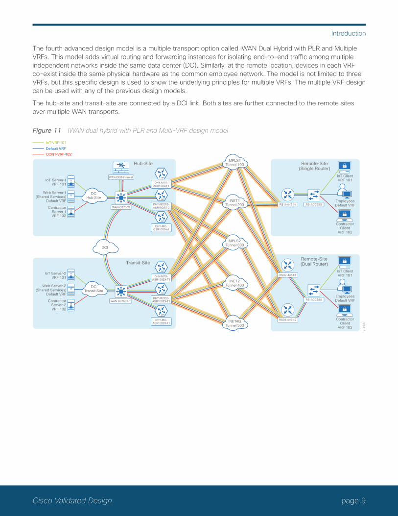
The fourth advanced design model is a multiple transport option called IWAN Dual Hybrid with PLR and Multiple VRFs. This model adds virtual routing and forwarding instances for isolating end-to-end traffic among multiple independent networks inside the same data center (DC). Similarly, at the remote location, devices in each VRF co-exist inside the same physical hardware as the common employee network. The model is not limited to three VRFs, but this specific design is used to show the underlying principles for multiple VRFs. The multiple VRF design can be used with any of the previous design models.
The hub-site and transit-site are connected by a DCI link. Both sites are further connected to the remote sites over multiple WAN transports.
Figure 11 IWAN dual hybrid with PLR and Multi-VRF design model
IoT ClientVRF 101
EmployeesDefault VRF
ContractorClient
VRF 102
70
89
F
IoT Server-1VRF 101
Hub-Site Remote-Site(Single Router)
Web Server-1(Shared Services)
Default VRF
ContractorServer-1VRF 102
IoT-VRF-101
Default VRF
CONT-VRF-102
WAN-DIST-Firewall
DCHub Site
DHY-M1I1-ASR1002X-1
DHY-M2I2I3-ASR1002X-2
DHY-MC-CSR1000v-1
IoT Server-2VRF 101
Transit-Site
Web Server-2(Shared Services)
Default VRF
ContractorServer-2VRF 102
DCTransit Site
WAN-D3750X
WAN-D3750X-T
DCI
DHY-M1I1-ASR1002X-T1
DHY-M2I2I3-ASR1002X-T2
DHY-MC-ASR1002X-T1
RS11-4451-1 RS-ACCESS
Remote-Site(Dual Router)
IoT ClientVRF 101
EmployeesDefault VRF
ContractorClient
VRF 102
RS-ACCESS
MPLS1Tunnel 100
MPLS2Tunnel 300
INET2Tunnel 400
INET4GTunnel 500
RS32-4451-1
RS32-4451-2
INET1Tunnel 200

page 10Cisco Validated Design
Product List
Product ListTo view the full list of IWAN-supported routers for this version of the CVD, see Supported Cisco Platforms and Software Releases. All master controllers and border router devices at a common site must use the same version of software.
This guide was validated using the software in this appendix. When deploying, you should always use the Cisco IOS Software Checker tool to see if there are software vulnerabilities applicable for your environment. This tool is available at the following location:
https://tools.cisco.com/security/center/selectIOSVersion.x

page 11Cisco Validated Design
IWAN Hybrid Design Model for EIGRP—WAN Aggregation
IWAN Hybrid Design Model for EIGRP—WAN AggregationPerformance Routing Version 3 (PfRv3) consists of two major Cisco IOS components: an MC and a border router (BR). The MC defines the policies and applies them to various traffic classes that traverse the BR systems. The MC can be configured to learn and control traffic classes on the network.
There are two different roles a device can play at the WAN aggregation site of a PfRv3 configuration:
• Hub master controller—The hub MC is the MC at the primary WAN aggregation site. This is the MC device where all PfRv3 policies are configured. It also acts as MC for that site and makes path-optimization decision. There is only one hub MC per IWAN domain.
• Hub border router—This is a BR at the hub MC site. This is the device where WAN interfaces terminate. There can be only one WAN interface on the device. There can be one or more hub BRs. On the Hub BRs, PfRv3 must be configured with:
◦ The address of the local MC.
◦ The path name on external interfaces.
page 12Cisco Validated Design
IWAN Hybrid Design Model for EIGRP—WAN Aggregation
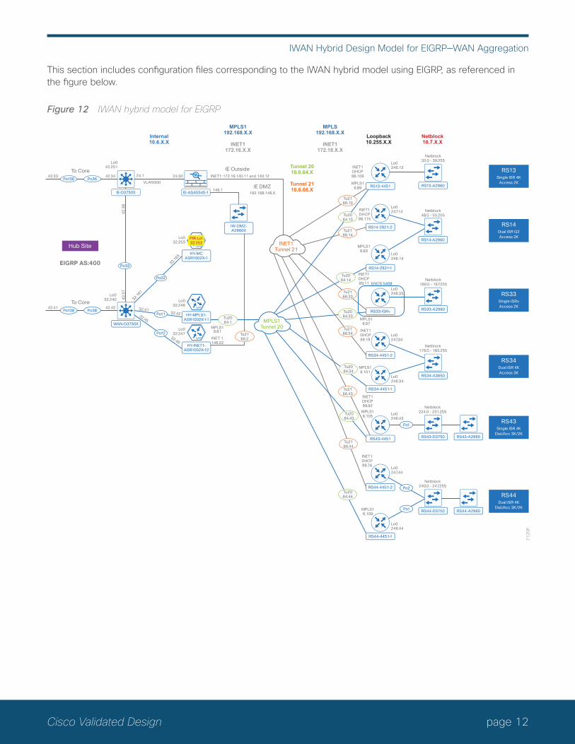
This section includes configuration files corresponding to the IWAN hybrid model using EIGRP, as referenced in the figure below.
Figure 12 IWAN hybrid model for EIGRP
WAN-D3750X
Po13842.41
To Core
Po3842.42
71
20
F
IE-D3750X IE-ASA5545-1
HY-MPLS1-ASR1002X-11
HY-MCASR1002X-1
IW-DMZ-A2960X
MPLS1Tunnel 20
RS13-4451
RS14-2921-1
ENCS 5408
RS14-2921-2
RS13-A2960
RS14-A2960
RS33-A2960
RS34-A3650
Po13642.33
To Core
Po3642.34 24.1 24.30
Po11
32.161
32.163
32.4132.42
Po22
Tu2166.14
Tu2166.13
Tu2166.33
Tu2166.34
Tu2166.43
Tu2166.44
INET1Tunnel 21
RS33-ISRv
RS34-4451-1
RS34-4451-2
Tu2064.13
Tu2064.14
Tu2064.33
Tu2064.34
Tu2064.43
Tu2064.44
Po1
Po2
Po1
Tu2064.1
IE OutsideINET1: 172.16.140.11 and 140.12
146.1IE DMZ
192.168.146.X
VLAN300
Po33
42
.38
42
.37
Lo042.251
MPLS16.81
Lo0246.13
Lo0247.14
Lo0246.14
Lo0246.33
Lo0247.34
Lo0246.34
INET1DHCP98.109
INET1DHCP98.115
MPLS16.89
INET1DHCP99.11
MPLS16.97
MPLS16.101
MPLS16.93
INET1DHCP99.19
Netblock32.0 - 39.255
Netblock48.0 - 55.255
Netblock160.0 - 167.255
Netblock176.0 - 183.255
Lo032.240
Lo032.253
Lo032.246
HY-INET1-ASR1002X-12
Po12
32.45
32.46
Tu2166.2INET 1
146.22
Lo032.247
Internal10.6.X.X
MPLS1192.168.X.X
INET1172.16.X.X
Tunnel 2010.6.64.X
Tunnel 2110.6.66.X
MPLS192.168.X.X
INET1172.18.X.X
Loopback10.255.X.X
Netblock10.7.X.X
Hub Site
EIGRP AS:400
RS13Single ISR 4K
Access 2K
RS34Dual ISR 4KAccess 3K
RS14Dual ISR G2Access 2K
RS33Single ISRvAccess 2K
RS43-D3750RS43-4451
Lo0246.43
INET1DHCP99.92
MPLS16.105
Netblock224.0 - 231.255
RS44-4451-2
Lo0247.44
RS44-D3750
RS44-4451-1
Lo0246.44
INET1DHCP99.76
MPLS16.109
Netblock240.0 - 247.255
RS43-A2960
RS44-A2960
RS43Single ISR 4K
Dist/Acc 3K/2K
RS44Dual ISR 4K
Dist/Acc 3K/2K
PfR Lo132.252
page 13Cisco Validated Design
IWAN Hybrid Design Model for EIGRP—WAN Aggregation
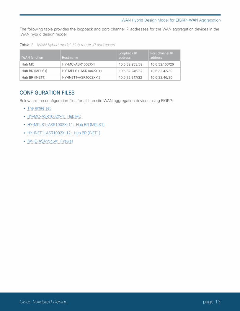
The following table provides the loopback and port-channel IP addresses for the WAN aggregation devices in the IWAN hybrid design model.
Table 1 IWAN hybrid model—Hub router IP addresses
IWAN function Host nameLoopback IP address
Port channel IP address
Hub MC HY-MC-ASR1002X-1 10.6.32.253/32 10.6.32.163/26
Hub BR (MPLS1) HY-MPLS1-ASR1002X-11 10.6.32.246/32 10.6.32.42/30
Hub BR (INET1) HY-INET1-ASR1002X-12 10.6.32.247/32 10.6.32.46/30
CoNFIGuRATIoN FILES Below are the configuration files for all hub site WAN aggregation devices using EIGRP:
• The entire set
• HY-MC-ASR1002X-1: Hub MC
• HY-MPLS1-ASR1002X-11: Hub BR (MPLS1)
• HY-INET1-ASR1002X-12: Hub BR (INET1)
• IW-IE-ASA5545X: Firewall

page 14Cisco Validated Design
IWAN Hybrid Design Model for EIGRP—Remote Sites
IWAN Hybrid Design Model for EIGRP—Remote SitesPerformance Routing Version 3 consists of two major Cisco IOS components: an MC and a BR. The MC defines the policies and applies them to various traffic classes that traverse the BR systems. The MC can be configured to learn and control traffic classes on the network.
There are two different roles a device can play at the remote site of a PfRv3 configuration:
• Branch master controller—The Branch MC is the MC at the branch-site. There is no policy configuration on this device. It receives policy from the Hub MC. This device acts as MC for that site for making path-optimi-zation decision. The configuration includes the IP address of the hub MC.
• Branch border router—This is a BR at the branch-site. The configuration on this device enables BR func-tionality and includes the IP address of the site local MC. The WAN interface that terminates on the device is detected automatically.
The following table provides the loopback IP addresses for the remote site devices in the IWAN hybrid design model.
Table 2 IWAN hybrid model—Remote site router IP addresses
IWAN function Host name Loopback IP address
Branch MC/BR (MPLS1/INET1) RS13-4451X 10.255.246.13/32
Branch MC/BR (MPLS1) RS14-2921-1 10.255.246.14/32
Branch BR (INET1) RS14-2921-2 10.255.247.14/32
Branch MC/BR (MPLS1/INET1) RS33-ISRv 10.255.246.33/32
Branch MC/BR (MPLS1) RS34-4451X-1 10.255.246.34/32
Branch BR (INET1) RS34-4451X-2 10.255.247.34/32
Branch MC/BR (MPLS1/INET1) RS43-4451X 10.255.246.43/32
Branch MC/BR (MPLS1) RS44-4451X-1 10.255.246.44/32
Branch BR (INET1) RS44-4451X-2 10.255.247.44/32

page 15Cisco Validated Design
IWAN Hybrid Design Model for EIGRP—Remote Sites
CoNFIGuRATIoN FILESBelow are the configuration files for all hybrid remote site devices using EIGRP:
• The entire set
• RS13—Single-Router, Two-Link, Access (MPLS1 and INET1):
◦ RS13-4451X: MPLS1 and INET1 WAN links
• RS14—Dual-Router, Two-Link, Access (MPLS1 and INET1):
◦ RS14-2921-1: MPLS1 WAN link
◦ RS14-2921-2: INET1 WAN link
• RS33—Single-Router, Two-Link, Access (MPLS1 and INET1):
◦ RS33-ISRv: MPLS1 and INET1 WAN links
• RS34—Dual-Router, Two-Link, Access (MPLS1 and INET1):
◦ RS34-4451X-1: MPLS1 WAN link
◦ RS34-4451X-2: INET1 WAN link
• RS43—Single-Router, Two-Link, Distribution (MPLS1 and INET1):
◦ RS43-4451X: MPLS1 and INET1 WAN links
• RS44—Dual-Router, Two-Link, Distribution (MPLS1 and INET1):
◦ RS44-4451X-1: MPLS1 WAN link
◦ RS44-4451X-2: INET1 WAN link

page 16Cisco Validated Design
IWAN Hybrid Design Model with MNH and MTT for EIGRP—WAN Aggregation
IWAN Hybrid Design Model with MNH and MTT for EIGRP—WAN AggregationPfRv3 consists of two major Cisco IOS components: an MC and a BR. The MC defines the policies and applies them to various traffic classes that traverse the BR systems. The MC can be configured to learn and control traffic classes on the network.
There are two different roles a device can play at the WAN aggregation site of a PfRv3 configuration:
• Hub master controller—The hub MC is the MC at the primary WAN aggregation site. This is the MC device where all PfRv3 policies are configured. It also acts as MC for that site and makes path-optimization decision. There is only one hub MC per IWAN domain.
• Hub border router—This is a BR at the hub MC site. This is the device where WAN interfaces terminate. There can be only one WAN interface on the device. There can be one or more hub BRs. On the Hub BRs, PfRv3 must be configured with:
◦ The address of the local MC.
◦ The path name on external interfaces.
This section of the guide also has hub MC high availability, hub BR scaling using the multiple next hop feature, and the multiple tunnel termination feature.
page 17Cisco Validated Design
IWAN Hybrid Design Model with MNH and MTT for EIGRP—WAN Aggregation
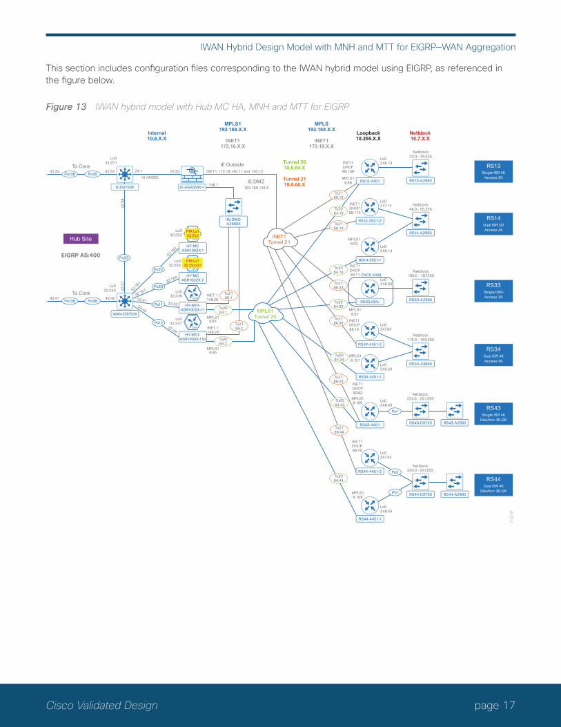
This section includes configuration files corresponding to the IWAN hybrid model using EIGRP, as referenced in the figure below.
Figure 13 IWAN hybrid model with Hub MC HA, MNH and MTT for EIGRP
WAN-D3750X
Po13842.41
To Core
Po3842.42
71
21
F
IE-D3750X IE-ASA5545-1
HY-M1l1-ASR1002X-11
HY-MCASR1002X-1
IW-DMZ-A2960X
MPLS1Tunnel 20
RS13-4451
RS14-2921-1
RS14-2921-2
RS13-A2960
RS14-A2960
RS33-A2960
RS34-A3650
Po13642.33
To Core
Po3642.34 24.1 24.30
Po11
32.161
32.163
32.161
32.164
32.4132.42
Po23
Po22
Tu2166.14
Tu2166.13
Tu2166.33
Tu2166.34
Tu2166.43
Tu2166.44
INET1Tunnel 21
RS33-ISRv
RS34-4451-1
RS34-4451-2
Tu2064.13
Tu2064.14
Tu2064.33
Tu2064.34
Tu2064.43
Tu2064.44
Po1
Po2
Po1
Tu2166.1
Tu2064.2
Tu2064.1
IE OutsideINET1: 172.16.140.11 and 140.12
146.1IE DMZ
192.168.146.X
VLAN300
Po33
42
.38
42
.37
Lo042.251
INET 1146.20
MPLS16.81
MPLS16.85
Lo0246.13
Lo0247.14
Lo0246.14
Lo0246.33
Lo0247.34
Lo0246.34
INET1DHCP98.109
INET1DHCP98.115
MPLS16.89
INET1DHCP99.11
MPLS16.97
MPLS16.101
MPLS16.93
INET1DHCP99.19
Netblock32.0 - 39.255
Netblock48.0 - 55.255
Netblock160.0 - 167.255
Netblock176.0 - 183.255
Lo032.240
Lo032.254
Lo032.253
Lo032.246
HY-M1l1-ASR1002X-11b
Po12
32.45
32.46
Tu2166.2INET 1
146.22
Lo032.247
Internal10.6.X.X
MPLS1192.168.X.X
INET1172.16.X.X
Tunnel 2010.6.64.X
Tunnel 2110.6.66.X
MPLS192.168.X.X
INET1172.18.X.X
Loopback10.255.X.X
Netblock10.7.X.X
Hub Site
EIGRP AS:400
RS13Single ISR 4K
Access 2K
RS34Dual ISR 4KAccess 3K
RS14Dual ISR G2Access 2K
RS33Single ISRvAccess 2K
RS43-D3750RS43-4451
Lo0246.43
INET1DHCP99.92
MPLS16.105
Netblock224.0 - 231.255
RS44-4451-2
Lo0247.44
RS44-D3750
RS44-4451-1
Lo0246.44
INET1DHCP99.76
MPLS16.109
Netblock240.0 - 247.255
RS43-A2960
RS44-A2960
RS43Single ISR 4K
Dist/Acc 3K/2K
RS44Dual ISR 4K
Dist/Acc 3K/2K
PfR Lo132.252
HY-MCASR1002X-2
PfR Lo132.252/31
ENCS 5408

page 18Cisco Validated Design
IWAN Hybrid Design Model with MNH and MTT for EIGRP—WAN Aggregation
The following table provides the loopback and port-channel IP addresses for the WAN aggregation devices in the IWAN hybrid design model.
Table 3 IWAN hybrid model with Hub MC HA, MNH and MTT—Hub router IP addresses
IWAN function Host nameLoopback0 IP address (Mgmt)
Loopback1 IP address (PfR)
Port channel IP address
Hub MC HY-MC-ASR1002X-1 10.6.32.253/32 10.6.32.252/32 10.6.32.163/26
Hub MC HA HY-MC-ASR1002X-2 10.6.32.254/32 10.6.32.252/31 10.6.32.164/26
Hub BR (MPLS1/INET1) HY-M1I1-ASR1002X-11 10.6.32.246/32 N/A 10.6.32.42/30
Hub BR (MPLS1/INET1) HY-M1I1-ASR1002X-11b 10.6.32.247/32 N/A 10.6.32.46/30
CoNFIGuRATIoN FILES Below are the configuration files for all hub site WAN aggregation devices using EIGRP:
• The entire set
• HY-MC-ASR1002X-1: Hub MC
• HY-MC-ASR1002X-2: Hub MC HA
• HY-M1I1-ASR1002X-11: Hub BR (MPLS1 and INET1)
• HY-M1I1-ASR1002X-11b: Hub BR (MPLS1 and INET1)
• IW-IE-ASA5545X: Firewall

page 19Cisco Validated Design
IWAN Hybrid Design Model with MNH and MTT for EIGRP—Remote Sites
IWAN Hybrid Design Model with MNH and MTT for EIGRP—Remote SitesPerformance Routing Version 3 consists of two major Cisco IOS components: an MC and a BR. The MC defines the policies and applies them to various traffic classes that traverse the BR systems. The MC can be configured to learn and control traffic classes on the network.
There are two different roles a device can play at the remote site of a PfRv3 configuration:
• Branch master controller—The Branch MC is the MC at the branch-site. There is no policy configuration on this device. It receives policy from the Hub MC. This device acts as MC for that site for making path-optimi-zation decision. The configuration includes the IP address of the hub MC.
• Branch border router—This is a BR at the branch-site. The configuration on this device enables BR func-tionality and includes the IP address of the site local MC. The WAN interface that terminates on the device is detected automatically.
The following table provides the loopback IP addresses for the remote site devices in the IWAN hybrid design model with multiple next hops (MNH) and MTT.
Table 4 IWAN hybrid model—Remote site router IP addresses
IWAN function Host name Loopback IP address
Branch MC/BR (MPLS1/INET1) RS13-4451X 10.255.246.13/32
Branch MC/BR (MPLS1) RS14-2921-1 10.255.246.14/32
Branch BR (INET1) RS14-2921-2 10.255.247.14/32
Branch MC/BR (MPLS1/INET1) RS33-ISRv 10.255.246.33/32
Branch MC/BR (MPLS1) RS34-4451X-1 10.255.246.34/32
Branch BR (INET1) RS34-4451X-2 10.255.247.34/32
Branch MC/BR (MPLS1/INET1) RS43-4451X 10.255.246.43/32
Branch MC/BR (MPLS1) RS44-4451X-1 10.255.246.44/32
Branch BR (INET1) RS44-4451X-2 10.255.247.44/32

page 20Cisco Validated Design
IWAN Hybrid Design Model with MNH and MTT for EIGRP—Remote Sites
CoNFIGuRATIoN FILESBelow are the configuration files for all hybrid remote site devices using EIGRP:
• The entire set
• RS13—Single-Router, Two-Link, Access (MPLS1 and INET1):
◦ RS13-4451X: MPLS1 and INET1 WAN links
• RS14—Dual-Router, Two-Link, Access (MPLS1 and INET1):
◦ RS14-2921-1: MPLS1 WAN link
◦ RS14-2921-2: INET1 WAN link
• RS33—Single-Router, Two-Link, Access (MPLS1 and INET1):
◦ RS33-ISRv: MPLS1 and INET1 WAN links
• RS34—Dual-Router, Two-Link, Access (MPLS1 and INET1):
◦ RS34-4451X-1: MPLS1 WAN link
◦ RS34-4451X-2: INET1 WAN link
• RS43—Single-Router, Two-Link, Distribution (MPLS1 and INET1):
◦ RS43-4451X: MPLS1 and INET1 WAN links
• RS44—Dual-Router, Two-Link, Distribution (MPLS1 and INET1):
◦ RS44-4451X-1: MPLS1 WAN link
◦ RS44-4451X-2: INET1 WAN link

page 21Cisco Validated Design
IWAN Dual Hybrid with PLR and MTT Design Model for BGP—WAN Aggregation with DCI
IWAN Dual Hybrid with PLR and MTT Design Model for BGP—WAN Aggregation with DCIPerformance Routing Version 3 consists of two major Cisco IOS components: an MC and a BR. The MC defines the policies and applies them to various traffic classes that traverse the BR systems. The MC can be configured to learn and control traffic classes on the network.
There are two different roles a device can play at the WAN aggregation site of a PfRv3 configuration:
• Hub master controller—The hub MC is the MC at the primary WAN aggregation site. This is the MC device where all PfRv3 policies are configured. It also acts as MC for that site and makes path-optimization decision. There is only one hub MC per IWAN domain.
• Hub border router—This is a BR at the hub MC site. This is the device where WAN interfaces terminate. There can be only one WAN interface on the device. There can be one or more hub BRs. On the Hub BRs, PfRv3 must be configured with:
◦ The address of the local MC.
◦ The path name on external interfaces.
This section also shows a second data center acting as a transit site with a transit MC and transit BRs.
• Transit master controller—The transit MC is the MC at the transit site. There is no policy configuration on this device. It receives policy from the hub MC. This device acts as MC for that site for making path optimization decisions. The configuration includes the IP address of the hub MC.
• Transit border router—This is a BR at the transit MC site. This is the device where WAN interfaces terminate. There can be only one WAN interface on the device. There can be one or more transit BRs. On the transit BRs, PfRv3 must be configured with:
◦ The address of the transit MC.
◦ The path name on external interfaces.
◦ The path ID on external interfaces.

page 22Cisco Validated Design
IWAN Dual Hybrid with PLR and MTT Design Model for BGP—WAN Aggregation with DCI
Finally, this section includes configuration files corresponding to the IWAN dual hybrid model with PLR and MTT using BGP on the WAN and OSPF on the LAN, as referenced in the figure below. There is a DCI link between the hub and transit site.
Figure 14 IWAN dual hybrid with PLR and MTT for BGP and OSPF with DCI
WAN-D3850
71
22
F
IE-D3850
DHY-M2l2l3-ASR1002X-2
DHY-M1l1-ASR1002X-1
DHY-MC-ASR1002X-1
Po13642.33
To Core
Po3642.34 24.1 24.30
32.1
32.2
32.5Po2
Po1
VLAN300
Po33
42
.38
42
.37
Lo042.251
Lo032.240
Lo032.242
Lo032.241
Lo032.251
Internal10.6.X.X
Po21
32.6
32.129 32.151
WAN-D3850-T
DHY-M2l2l3-CSR1000v-T2
DHY-M1l1-CSR1000v-T1
DHY-MC-CSR1000v-T1
32.1
32.2
32.5Po2
Po1
Po35
42.38
42.37
Lo032.240 Lo0
32.242
Lo032.241
Lo032.251
Po21
32.6
32.129
32.151
Tu1034.1
Tu1238.1
Tu1340.1
65100:100
Tunnel10010.6.34.X
Tunnel30010.6.38.X
Tunnel20010.6.36.X
Tunnel40010.6.40.X
Tunnel50010.6.42.X
Loopback10.255.X.X
Netblock10.7.X.X
BGPCommunity
Attribute
BGP AS:65100in WAN Overlay
OSPF 100Area 0
OSPF 100Area 0
OSPF 100Area 0
OSPF 100Area 0
OSPF 100Area 0
BGPCommunity
Attribute
Hub Site(POP1)
MPLS1=65100:100INET1=65100:200
MPLS2=65100:300INET2=65100:400
INET4G=65100:500
Transit Site(POP2)
MPLS1=65100:101INET1=65100:201
MPLS2=65100:301INET2=65100:401
INET4G=65100:501
PreferPOP2
65100:20
Tu1136.2
Tu1034.2
Tu1238.2
Tu1340.2
Tu1444.2
INET1Tunnel 200
MPLS1Tunnel 100
INET2Tunnel 400
MPLS2Tunnel 300
INET PLRTunnel 500
RS11-2921 RS11-A2960
Lo0241.11
Netblock0.0 - 7.255
RS11Single ISR G2
Access 2K
RS12Dual ISRv
Access 2K
PreferPOP1
65100:10
RS31Single ISR 4K
Access 2K
RS32Dual ISR 4KAccess 3K
PreferPOP1
65100:10
RS41Single ISR 4K
Dist/Acc 3K/2K
PreferPOP2
65100:20
RS42Dual ISR 4K
Dist/Acc 3K/3K
Tu1136.11
Tu1034.11
RS12-ISRv-1
RS12-A2960
LoO241.12
Netblock16.0 - 23.255
Tu1136.12
Tu1034.12
Tu1034.32
Tu1034.41
RS12-ISRv-2
Lo0243.12
RS31-4451
ENCS 5408
ENCS 5408
RS31-A2960
Lo0243.31
Netblock128.0 - 135.255
RS32-4451-1
RS32-A3850
Lo0241.32
Netblock144.0 - 151.255
RS32-4451-2
Lo0243.32
RS41-4451 RS41-D3750
Lo0241.41
Netblock192.0 - 199.255
RS42-4451-1
RS42-D3850
RS41-A2960
RS42-A3650
Lo0241.42
Netblock208.0 - 215.255
RS42-4451-2
Lo0243.42
Tu1238.12
Tu1340.12
Tu1238.31
Tu1238.32
Tu1238.42
Tu1340.31
Tu1340.32
Tu1340.42
Tu1136.32
Tu1136.41
Tu1034.42
Tu1136.42
Tu1444.31
Tu1444.31
Tu1136.1
Tu1444.1
Po1
Po1
Po2
65100:20
65100:20
65100:10
65100:10
65100:10
65100:10
65100:10
65100:20
65100:20
65100:20
65100:300
65100:400
65100:500
65100:101
65100:201
65100:301
65100:401
65100:501
65100:200
To IE-D3750X
Internal10.8.X.X
IE-ASA5545-1
V350
V1110
V1120
Po10
10
.8.3
2.9
8
DCI
10
.8.3
2.9
7
Po45

page 23Cisco Validated Design
IWAN Dual Hybrid with PLR and MTT Design Model for BGP—WAN Aggregation with DCI
The following tables provide the loopback and port-channel IP addresses for the WAN aggregation devices with DCI in the IWAN dual hybrid with PLR and MTT design model.
Table 5 IWAN dual hybrid with PLR and MTT model—Hub router IP addresses
IWAN function Host nameLoopback IP address
Port channel IP address
Hub MC DHY-MC-ASR1002X-1 10.6.32.251/32 10.6.32.151/26
Hub BR (MPLS1 & INET1) DHY-M1I1-ASR1002X-1 10.6.32.241/32 10.6.32.2/30
Hub BR (MPLS2, INET2 and PLR) DHY-M2I2I3-ASR1002X-2 10.6.32.242/32 10.6.32.6/30
Table 6 IWAN dual hybrid with PLR and MTT model—Transit router IP addresses
IWAN function Host nameLoopback IP address
Port channel IP address
Transit MC DHY-MC-CSR1000v-T1 10.8.32.251/32 10.8.32.151/26
Transit BR (MPLS1 & INET1) DHY-M1I1-CSR1000v-T1 10.8.32.241/32 10.8.32.2/30
Transit BR (MPLS2, INET2 and PLR) DHY-M2I2I3-CSR1000v-T2 10.8.32.242/32 10.8.32.6/30
CoNFIGuRATIoN FILESBelow are links to the configuration files for all dual hybrid with PLR and MTT hub and transit site WAN aggrega-tion devices with DCI using BGP and OSPF:
• The entire set
• DHY-MC-ASR1002X-1: Hub MC, BGP
• DHY-M1I1-ASR1002X-1: Hub BR, BGP (MPLS1 & INET1)
• DHY-M2I2I3-ASR1002X-2: Hub BR, BGP (MPLS2, INET2 & PLR)
• DHY-MC-CSR1000v-T1: Transit MC, BGP
• DHY-M1I1-CSR1000v-T1: Transit BR, BGP (MPLS1 & INET1)
• DHY-M2I2I3-CSR1000v-T2: Transit BR, BGP (MPLS2, INET2 & PLR)
• IW-WAN-D3750X: Hub WAN Agg Distribution Switch
• IW-WAN-D3750X-T: Transit WAN Agg Distribution Switch
• IW-IE-ASA5545X: Firewall

page 24Cisco Validated Design
IWAN Dual Hybrid with PLR and MTT Design Model for BGP—WAN Aggregation without DCI
IWAN Dual Hybrid with PLR and MTT Design Model for BGP—WAN Aggregation without DCIPerformance Routing Version 3 consists of two major Cisco IOS components: an MC and a BR. The MC defines the policies and applies them to various traffic classes that traverse the BR systems. The MC can be configured to learn and control traffic classes on the network.
There are two different roles a device can play at the WAN aggregation site of a PfRv3 configuration:
• Hub master controller—The hub MC is the MC at the primary WAN aggregation site. This is the MC device where all PfRv3 policies are configured. It also acts as MC for that site and makes path-optimization decision. There is only one hub MC per IWAN domain.
• Hub border router—This is a BR at the hub MC site. This is the device where WAN interfaces terminate. There can be only one WAN interface on the device. There can be one or more hub BRs. On the Hub BRs, PfRv3 must be configured with:
◦ The address of the local MC.
◦ The path name on external interfaces.
This section also shows a second data center acting as a transit site with:
• Transit master controller—The transit MC is the MC at the transit site. There is no policy configuration on this device. It receives policy from the hub MC. This device acts as MC for that site for making path optimization decisions. The configuration includes the IP address of the hub MC.
• Transit border router—This is a BR at the transit MC site. This is the device where WAN interfaces terminate. There can be only one WAN interface on the device. There can be one or more transit BRs. On the transit BRs, PfRv3 must be configured with:
◦ The address of the transit MC.
◦ The path name on external interfaces.
◦ The path ID on external interfaces.

page 25Cisco Validated Design
IWAN Dual Hybrid with PLR and MTT Design Model for BGP—WAN Aggregation without DCI
Finally, this section includes configuration files corresponding to the IWAN dual hybrid model with PLR and MTT using BGP on the WAN and OSPF on the LAN, as referenced in the figure below. There is not a DCI link between the hub and transit site.
Figure 15 IWAN dual hybrid with PLR and MTT model for BGP and OSPF without DCI
WAN-D3850
71
23
F
IE-D3850
DHY-M2l2l3-ASR1002X-2
DHY-M1l1-ASR1002X-1
DHY-MC-ASR1002X-1
Po13642.33
To Core
Po3642.34 24.1 24.30
32.1
32.2
32.5Po2
Po1
VLAN300
Po33
42
.38
42
.37
Lo042.251
Lo032.240
Lo032.242
Lo032.241
Lo032.251
Internal10.6.X.X
Po21
32.6
32.129 32.151
WAN-D3850-T
DHY-M2l2l3-CSR1000v-T2
DHY-M1l1-CSR1000v-T1
DHY-MC-CSR1000v-T1
32.1
32.2
32.5Po2
Po1
Lo032.240 Lo0
32.242
Lo032.241
Lo032.251
Po21
32.6
32.129
32.151
Tu1034.1
Tu1238.1
Tu1340.1
65100:100
Tunnel10010.6.34.X
Tunnel30010.6.38.X
Tunnel20010.6.36.X
Tunnel40010.6.40.X
Tunnel50010.6.42.X
Loopback10.255.X.X
Netblock10.7.X.X
BGPCommunity
Attribute
BGP AS:65100in WAN Overlay
OSPF 100Area 0
OSPF 100Area 0
OSPF 100Area 0
OSPF 100Area 0
OSPF 100Area 0
BGPCommunity
Attribute
Hub Site(POP1)
MPLS1=65100:100INET1=65100:200
MPLS2=65100:300INET2=65100:400
INET4G=65100:500
Transit Site(POP2)
MPLS1=65100:101INET1=65100:201
MPLS2=65100:301INET2=65100:401
INET4G=65100:501
PreferPOP2
65100:20
Tu1136.2
Tu1034.2
Tu1238.2
Tu1340.2
Tu1444.2
INET1Tunnel 200
MPLS1Tunnel 100
INET2Tunnel 400
MPLS2Tunnel 300
INET PLRTunnel 500
RS11-2921 RS11-A2960
Lo0241.11
Netblock0.0 - 7.255
RS11Single ISR G2
Access 2K
RS12Dual ISRv
Access 2K
PreferPOP1
65100:10
RS31Single ISR 4K
Access 2K
RS32Dual ISR 4KAccess 3K
PreferPOP1
65100:10
RS41Single ISR 4K
Dist/Acc 3K/2K
PreferPOP2
65100:20
RS42Dual ISR 4K
Dist/Acc 3K/3K
Tu1136.11
Tu1034.11
RS12-ISRv-1
RS12-A2960
LoO241.12
Netblock16.0 - 23.255
Tu1136.12
Tu1034.12
Tu1034.32
Tu1034.41
RS12-ISRv-2
Lo0243.12
RS31-4451
ENCS 5408
ENCS 5408
RS31-A2960
Lo0243.31
Netblock128.0 - 135.255
RS32-4451-1
RS32-A3850
Lo0241.32
Netblock144.0 - 151.255
RS32-4451-2
Lo0243.32
RS41-4451 RS41-D3750
Lo0241.41
Netblock192.0 - 199.255
RS42-4451-1
RS42-D3850
RS41-A2960
RS42-A3650
Lo0241.42
Netblock208.0 - 215.255
RS42-4451-2
Lo0243.42
Tu1238.12
Tu1340.12
Tu1238.31
Tu1238.32
Tu1238.42
Tu1340.31
Tu1340.32
Tu1340.42
Tu1136.32
Tu1136.41
Tu1034.42
Tu1136.42
Tu1444.31
Tu1444.31
Tu1136.1
Tu1444.1
Po1
Po1
Po2
65100:20
65100:20
65100:10
65100:10
65100:10
65100:10
65100:10
65100:20
65100:20
65100:20
65100:300
65100:400
65100:500
65100:101
65100:201
65100:301
65100:401
65100:501
65100:200
Internal10.8.X.X
IE-ASA5545-1
V350
V1110
V1120
Po45
OSPF 100Area 0

page 26Cisco Validated Design
IWAN Dual Hybrid with PLR and MTT Design Model for BGP—WAN Aggregation without DCI
The following tables provide the loopback and port-channel IP addresses for the WAN aggregation devices with-out DCI in the IWAN dual hybrid with PLR and MTT design model.
Table 7 IWAN dual hybrid with PLR and MTT model—Hub router IP addresses
IWAN function Host nameLoopback IP address
Port channel IP address
Hub MC DHY-MC-ASR1002X-1 10.6.32.251/32 10.6.32.151/26
Hub BR (MPLS1 & INET1) DHY-M1I1-ASR1002X-1 10.6.32.241/32 10.6.32.2/30
Hub BR (MPLS2, INET2 and PLR) DHY-M2I2I3-ASR1002X-2 10.6.32.242/32 10.6.32.6/30
Table 8 IWAN dual hybrid with PLR and MTT model—Transit router IP addresses
IWAN function Host nameLoopback IP address
Port channel IP address
Transit MC DHY-MC-CSR1000v-T1 10.8.32.251/32 10.8.32.151/26
Transit BR (MPLS1 & INET1) DHY-M1I1-CSR1000v-T1 10.8.32.241/32 10.8.32.2/30
Transit BR (MPLS2, INET2 and PLR) DHY-M2I2I3-CSR1000v-T2 10.8.32.242/32 10.8.32.6/30
CoNFIGuRATIoN FILESBelow are links to the configuration files for all dual hybrid with PLR and MTT hub and transit site WAN aggrega-tion devices without DCI using BGP and OSPF:
• The entire set
• DHY-MC-ASR1002X-1: Hub MC, BGP, No DCI
• DHY-M1I1-ASR1002X-1: Hub BR, BGP, No DCI (MPLS1 & INET1)
• DHY-M2I2I3-ASR1002X-2: Hub BR, BGP, No DCI (MPLS2, INET2 & PLR)
• DHY-MC-CSR1000v-T1: Transit MC, BGP, No DCI
• DHY-M1I1-CSR1000v-T1: Transit BR, BGP, No DCI (MPLS1 & INET1)
• DHY-M2I2I3-CSR1000v-T2: Transit BR, BGP, No DCI (MPLS2, INET2 & PLR)

page 27Cisco Validated Design
IWAN Dual Hybrid with PLR and MTT Design Model for BGP—Remote Sites
IWAN Dual Hybrid with PLR and MTT Design Model for BGP—Remote SitesThe remote site configuration files are the same for this design with or without a DCI link between the hub and transit site locations.
Performance Routing Version 3 consists of two major Cisco IOS components: an MC and a BR. The MC defines the policies and applies them to various traffic classes that traverse the BR systems. The MC can be configured to learn and control traffic classes on the network.
There are two different roles a device can play at the remote site of a PfRv3 configuration:
• Branch master controller—The Branch MC is the MC at the branch-site. There is no policy configuration on this device. It receives policy from the Hub MC. This device acts as MC for that site for making path-optimi-zation decision. The configuration includes the IP address of the hub MC.
• Branch border router—This is a BR at the branch-site. The configuration on this device enables BR func-tionality and includes the IP address of the site local MC. The WAN interface that terminates on the device is detected automatically.
The following table provides the loopback IP addresses for the remote site devices in the IWAN dual hybrid with PLR and MTT design model.
Table 9 IWAN dual hybrid with PLR and MTT model—Remote site router IP addresses
IWAN function Host name Loopback IP address
Branch MC/BR (MPLS1/INET1) RS11-2921 10.255.241.11/32
Branch MC/BR (MPLS1/INET1) RS12-ISRv-1 10.255.241.12/32
Branch BR (MPLS2/INET2) RS12-ISRv-2 10.255.243.12/32
Branch MC/BR (MPLS2/INET2/PLR) RS31-4451X 10.255.243.31/32
Branch MC/BR (MPLS1/INET1/PLR) RS32-4451X-1 10.255.241.32/32
Branch BR (MPLS2/INET2) RS32-4451X-2 10.255.243.32/32
Branch MC/BR (MPLS1/INET1) RS41-4451X 10.255.243.41/32
Branch MC/BR (MPLS1/INET1) RS42-4451X-1 10.255.241.42/32
Branch BR (MPLS2/INET2) RS42-4451X-2 10.255.243.42/32

page 28Cisco Validated Design
IWAN Dual Hybrid with PLR and MTT Design Model for BGP—Remote Sites
CoNFIGuRATIoN FILESBelow are links to the configuration files for all dual hybrid with PLR and MTT remote site devices using BGP and OSPF:
• The entire set
• RS11—Single-Router, Two-Link, Access, BGP (MPLS1 and INET1):
◦ RS11-2921: MPLS1 and INET1 WAN links
• RS12—Dual-Router, Four-Link, Access, BGP (MPLS1, MPLS2, INET1 and INET2):
◦ RS12-ISRv-1: MPLS1 and INET1 WAN links
◦ RS12-ISRv-2: MPLS2 and INET2 WAN links
• RS31—Single-Router, Three-Link, Access, BGP (MPLS2, INET2 and PLR):
◦ RS31-4451X: MPLS2, INET2 and PLR WAN links
• RS32—Dual-Router, Five-Link, Access, BGP (MPLS1, MPLS2, INET1, INET2 and PLR):
◦ RS32-4451X-1: MPLS1, INET1 and PLR WAN links
◦ RS32-4451X-2: MPLS2 and INET2 WAN links
• RS41—Single-Router, Two-Link, Distribution, BGP (MPLS1 and INET1):
◦ RS41-4451X: MPLS1 and INET1 WAN links
• RS42—Dual-Router, Four-Link, Distribution, BGP (MPLS1, MPLS2, INET1 and INET2):
◦ RS42-4451X-1: MPLS1 and INET1 WAN links
◦ RS42-4451X-2: MPLS2 and INET2 WAN links

page 29Cisco Validated Design
IWAN Dual Hybrid with PLR and Multi-VRF Design Model for BGP—WAN Aggregation
IWAN Dual Hybrid with PLR and Multi-VRF Design Model for BGP—WAN AggregationPerformance Routing Version 3 consists of two major Cisco IOS components: an MC and a BR. The MC defines the policies and applies them to various traffic classes that traverse the BR systems. The MC can be configured to learn and control traffic classes on the network.
There are two different roles a device can play at the WAN aggregation site of a PfRv3 configuration:
• Hub master controller—The hub MC is the MC at the primary WAN aggregation site. This is the MC device where all PfRv3 policies are configured. It also acts as MC for that site and makes path-optimization decision. There is only one hub MC per IWAN domain.
• Hub border router—This is a BR at the hub MC site. This is the device where WAN interfaces terminate. There can be only one WAN interface on the device. There can be one or more hub BRs. On the Hub BRs, PfRv3 must be configured with:
◦ The address of the local MC.
◦ The path name on external interfaces.
This section also shows a second data center acting as a transit site with a transit MC and transit BRs.
• Transit master controller—The transit MC is the MC at the transit site. There is no policy configuration on this device. It receives policy from the hub MC. This device acts as MC for that site for making path optimization decisions. The configuration includes the IP address of the hub MC.
• Transit border router—This is a BR at the transit MC site. This is the device where WAN interfaces terminate. There can be only one WAN interface on the device. There can be one or more transit BRs. On the transit BRs, PfRv3 must be configured with:
◦ The address of the transit MC.
◦ The path name on external interfaces.
◦ The path ID on external interfaces.
In order to enable inter-VRF route leaking, a Cisco firewall is configured with static routes. It is attached to the hub-site WAN distribution switch, and a very basic configuration is included here as a reference only.
page 30Cisco Validated Design
IWAN Dual Hybrid with PLR and Multi-VRF Design Model for BGP—WAN Aggregation
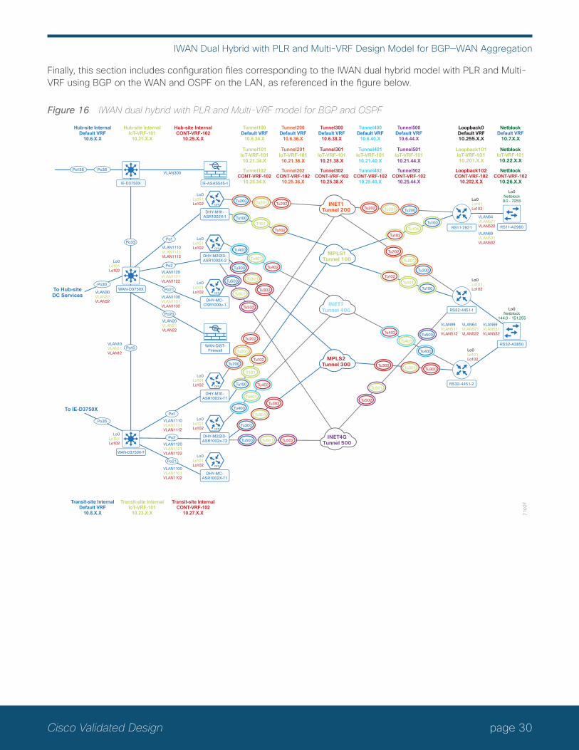
Finally, this section includes configuration files corresponding to the IWAN dual hybrid model with PLR and Multi-VRF using BGP on the WAN and OSPF on the LAN, as referenced in the figure below.
Figure 16 IWAN dual hybrid with PLR and Multi-VRF model for BGP and OSPF
71
02
F
IE-D3750X
DHY-MC-CSR1000v-1
Po136 Po36
Po30
Po2
Po1Po33
Lo0Lo101Lo102
Lo0Lo101Lo102
Lo0Lo101Lo102
Lo0Lo101Lo102
Lo0Lo101Lo102VLAN1110
VLAN1111VLAN1112
VLAN64VLAN521VLAN522
VLAN69VLAN531VLAN532
VLAN1120VLAN1121VLAN1122
VLAN1100VLAN1101VLAN1102
VLAN1110VLAN1111VLAN1112
VLAN1120VLAN1121VLAN1122
VLAN1100VLAN1101VLAN1102
VLAN20VLAN21VLAN22
VLAN30VLAN31VLAN32
VLAN10VLAN11VLAN12
Lo0Lo101Lo102
Lo0Lo101Lo102
Lo0Lo101Lo102
Lo0Lo101Lo102
Hub-site InternalDefault VRF
10.6.X.X
Hub-site InternalIoT-VRF-101
10.21.X.X
Tunnel100Default VRF
10.6.34.X
Tunnel101IoT-VRF-10110.21.34.X
Tunnel102CONT-VRF-102
10.25.34.X
Tunnel200Default VRF
10.6.36.X
Tunnel201IoT-VRF-10110.21.36.X
Tunnel202CONT-VRF-102
10.25.36.X
Tunnel300Default VRF
10.6.38.X
Tunnel301IoT-VRF-10110.21.38.X
Tunnel302CONT-VRF-102
10.25.38.X
Tunnel400Default VRF
10.6.40.X
Tunnel401IoT-VRF-10110.21.40.X
Tunnel402CONT-VRF-102
10.25.40.X
Tunnel500Default VRF
10.6.44.X
Tunnel501IoT-VRF-10110.21.44.X
Tunnel502CONT-VRF-102
10.25.44.X
Hub-site InternalCONT-VRF-102
10.25.X.X
Transit-site InternalDefault VRF
10.8.X.X
Transit-site InternalIoT-VRF-101
10.23.X.X
Transit-site InternalCONT-VRF-102
10.27.X.X
Po21
Po20
VLAN300
DHY-M2l2l3-ASR1002x-T2
DHY-M1l1-ASR1002x-T1
DHY-MC-ASR1002X-T1
Po2
Po1
Po10
Po21
Loopback0Default VRF10.255.X.X
NetblockDefault VRF
10.7.X.X
Loopback101IoT-VRF-10110.201.X.X
NetblockIoT-VRF-10110.22.X.X
Loopback102CONT-VRF-102
10.202.X.X
NetblockCONT-VRF-102
10.26.X.X
Tu200 Tu201 Tu202Tu202 Tu201 Tu200
Tu102
Tu101
Tu100
Tu102
Tu101
Tu402
Tu401
Tu100
Tu500
Tu400
Tu501
Tu502
Tu202
Tu201
Tu200
Tu200
Tu201
Tu202
Tu400
Tu401
Tu402
Tu400
Tu401
Tu402
Tu300
Tu301
Tu302
Tu500 Tu501 Tu502
Tu100T101
Tu102
Tu100
T101
Tu102
INET1Tunnel 200
MPLS1Tunnel 100
INET4GTunnel 500
RS11-2921 RS11-A2960
Lo0Netblock0.0 - 7.255
Lo0Lo101Lo102
VLAN64VLAN521VLAN522
VLAN99VLAN511VLAN512
VLAN69VLAN531VLAN532
RS32-4451-1
Lo0Lo101Lo102
RS32-A3850
Lo0Netblock
144.0 - 151.255
IE-ASA5545-1
WAN-DIST-Firewall
WAN-D3750XTo Hub-siteDC Services
Po35
To IE-D3750X
DHY-M1l1-ASR1002X-1
WAN-D3750X-T
DHY-M2l2l3-ASR1002X-2
INET2Tunnel 400
Tu300
Tu301
Tu302
Tu500
Tu501
Tu502
RS32-4451-2
MPLS2Tunnel 300 Tu302
Tu301 Tu300

page 31Cisco Validated Design
IWAN Dual Hybrid with PLR and Multi-VRF Design Model for BGP—WAN Aggregation
The following tables provide the loopback and port-channel IP addresses for the WAN aggregation devices in the IWAN dual hybrid with PLR and Multi-VRF design model.
Table 10 IWAN dual hybrid with PLR and Multi-VRF model—Hub and transit router IP addresses (Default VRF)
IWAN function Host nameLoopback IP address
Port channel IP address
Hub MC DHY-MC-CSR1000V-1 10.6.32.251/32 10.6.32.151/26
Hub BR (MPLS1 & INET1) DHY-M1I1-ASR1002X-1 10.6.32.241/32 10.6.32.2/30
Hub BR (MPLS2, INET2 and PLR) DHY-M2I2I3-ASR1002X-2 10.6.32.242/32 10.6.32.6/30
Transit MC DHY-MC-ASR1002X-T1 10.8.32.251/32 10.8.32.151/26
Transit BR (MPLS1 & INET1) DHY-M1I1-ASR1002X-T1 10.8.32.241/32 10.8.32.2/30
Transit BR (MPLS2, INET2 and PLR) DHY-M2I2I3-ASR1002X-T2 10.8.32.242/32 10.8.32.6/30
Table 11 IWAN dual hybrid with PLR and Multi-VRF model—Hub and transit router IP addresses (IoT-VRF-101)
IWAN function Host nameLoopback IP address
Port channel IP address
Hub MC DHY-MC-CSR1000V-1 10.21.32.251/32 10.21.32.151/26
Hub BR (MPLS1 & INET1) DHY-M1I1-ASR1002X-1 10.21.32.241/32 10.21.32.2/30
Hub BR (MPLS2, INET2 and PLR) DHY-M2I2I3-ASR1002X-2 10.21.32.242/32 10.21.32.6/30
Transit MC DHY-MC-ASR1002X-T1 10.23.32.251/32 10.23.32.151/26
Transit BR (MPLS1 & INET1) DHY-M1I1-ASR1002X-T1 10.23.32.241/32 10.23.32.2/30
Transit BR (MPLS2, INET2 and PLR) DHY-M2I2I3-ASR1002X-T2 10.23.32.242/32 10.23.32.6/30
Table 12 IWAN dual hybrid with PLR and Multi-VRF model—Hub and transit router IP addresses (CONT-VRF-102)
IWAN function Host nameLoopback IP address
Port channel IP address
Hub MC DHY-MC-CSR1000V-1 10.25.32.251/32 10.25.32.151/26
Hub BR (MPLS1 & INET1) DHY-M1I1-ASR1002X-1 10.25.32.241/32 10.25.32.2/30
Hub BR (MPLS2, INET2 and PLR) DHY-M2I2I3-ASR1002X-2 10.25.32.242/32 10.25.32.6/30
Transit MC DHY-MC-ASR1002X-T1 10.27.32.251/32 10.27.32.151/26
Transit BR (MPLS1 & INET1) DHY-M1I1-ASR1002X-T1 10.27.32.241/32 10.27.32.2/30
Transit BR (MPLS2, INET2 and PLR) DHY-M2I2I3-ASR1002X-T2 10.27.32.242/32 10.27.32.6/30

page 32Cisco Validated Design
IWAN Dual Hybrid with PLR and Multi-VRF Design Model for BGP—WAN Aggregation
CoNFIGuRATIoN FILESBelow are links to the configuration files for all dual hybrid with PLR and Multi-VRF hub and transit site WAN ag-gregation devices using BGP and OSPF:
• The entire set
• DHY-MC-CSR1000V-1: Hub MC, BGP
• DHY-M1I1-ASR1002X-1: Hub BR, BGP (MPLS1 & INET1)
• DHY-M2I2I3-ASR1002X-2: Hub BR, BGP (MPLS2, INET2 & PLR)
• DHY-MC-ASR1002X-T1: Transit MC, BGP
• DHY-M1I1-ASR1002X-T1: Transit BR, BGP (MPLS1 & INET1)
• DHY-M2I2I3-ASR1002X-T2: Transit BR, BGP (MPLS2, INET2 & PLR)
• IW-WAN-D3750X: Hub WAN Agg Distribution Switch
• IW-WAN-D3750X-T: Transit WAN Agg Distribution Switch
• IW-IE-ASA5545X: Firewall
• DIST-WAN-FW: Hub-site inter-VRF route leaking firewall

page 33Cisco Validated Design
IWAN Dual Hybrid with PLR and Multi-VRF Design Model for BGP—Remote Sites
IWAN Dual Hybrid with PLR and Multi-VRF Design Model for BGP—Remote SitesPerformance Routing Version 3 consists of two major Cisco IOS components: an MC and a BR. The MC defines the policies and applies them to various traffic classes that traverse the BR systems. The MC can be configured to learn and control traffic classes on the network.
There are two different roles a device can play at the remote site of a PfRv3 configuration:
• Branch master controller—The branch MC is the MC at the branch-site. There is no policy configuration on this device. It receives policy from the hub MC. This device acts as MC for that site for making path-optimi-zation decision. The configuration includes the IP address of the hub MC.
• Branch border router—This is a BR at the branch-site. The configuration on this device enables BR func-tionality and includes the IP address of the site local MC. The WAN interface that terminates on the device is detected automatically.
The following tables provide the loopback IP addresses for the remote site devices in the IWAN dual hybrid with PLR and Multi-VRF design model.
Table 13 IWAN dual hybrid with PLR and Multi-VRF model—Remote site router IP addresses (Default VRF)
IWAN function Host name Loopback IP address
Branch MC/BR (MPLS1/INET1) RS11-2921 10.255.241.11/32
Branch MC/BR (MPLS1/INET1/PLR) RS32-4451-1 10.255.241.32/32
Branch BR (MPLS2/INET2) RS32-4451-2 10.255.243.32/32
Table 14 IWAN dual hybrid with PLR and Multi-VRF model—Remote site router IP addresses (IoT-VRF-101)
IWAN function Host name Loopback IP address
Branch MC/BR (MPLS1/INET1) RS11-2921 10.201.241.11/32
Branch MC/BR (MPLS1/INET1/PLR) RS32-4451-1 10.201.241.32/32
Branch BR (MPLS2/INET2) RS32-4451-2 10.201.243.32/32
Table 15 IWAN dual hybrid with PLR and Multi-VRF model—Remote site router IP addresses (CONT-VRF-102)
IWAN function Host name Loopback IP address
Branch MC/BR (MPLS1/INET1) RS11-2921 10.202.241.11/32
Branch MC/BR (MPLS1/INET1/PLR) RS32-4451-1 10.202.241.32/32
Branch BR (MPLS2/INET2) RS32-4451-2 10.202.243.32/32

page 34Cisco Validated Design
IWAN Dual Hybrid with PLR and Multi-VRF Design Model for BGP—Remote Sites
CoNFIGuRATIoN FILESBelow are links to the configuration files for all dual hybrid with PLR and Multi-VRF remote site devices using BGP and OSPF:
• The entire set
• RS11—Single-Router, Two-Link, Access, BGP (MPLS1 and INET1):
◦ RS11-2921: MPLS1 and INET1 WAN links
• RS32—Dual-Router, Five-Link, Access, BGP (MPLS1, MPLS2, INET1, INET2 and PLR):
◦ RS32-4451-1: MPLS1, INET1 and PLR WAN links
◦ RS32-4451-2: MPLS2 and INET2 WAN links

page 35Cisco Validated Design
Appendix A: Changes
Appendix A: ChangesThis appendix summarizes the changes Cisco made to this guide since its last edition.
• Routing updates:
◦ Added non-DCI configurations for hub and transit site BRs
◦ Added maximum secondary paths to remote site routers
◦ Updated the tunnel interface and tunnel ID numbering to match other guides
◦ Updated EIGRP tag numbering to match other guides
◦ Updated PLR labels to match other guides
• QoS updates:
◦ Added support for multiple sender QoS
◦ Changed ip nhrp map group to nhrp map group to be consistent with later IOS versions
◦ Changed ip nhrp group to nhrp group to be consistent with later IOS versions
• Model update:
◦ Changed dual Internet model to hybrid model
• Platform updates:
◦ Added support for CSR1000v as BRs at hub and transit sites
◦ Added support for ISRv at remote sites
• Guide updates:
◦ Added hybrid base configurations
◦ Removed dual hybrid non-MTT configurations

Americas HeadquartersCisco Systems, Inc.San Jose, CA
Asia Pacific HeadquartersCisco Systems (USA) Pte. Ltd.Singapore
Europe HeadquartersCisco Systems International BV Amsterdam,The Netherlands
Cisco has more than 200 offices worldwide. Addresses, phone numbers, and fax numbers are listed on the Cisco Website at www.cisco.com/go/offices.
ALL DESIGNS, SPECIFICATIONS, STATEMENTS, INFORMATION, AND RECOMMENDATIONS (COLLECTIVELY, “DESIGNS”) IN THIS MANUAL ARE PRESENTED “AS IS,” WITH ALL FAULTS. CISCO AND ITS SUPPLIERS DISCLAIM ALL WARRANTIES, INCLUDING, WITHOUT LIMITATION, THE WARRANTY OF MERCHANTABILITY, FITNESS FOR A PARTICULAR PURPOSE AND NONINFRINGEMENT OR ARISING FROM A COURSE OF DEALING, USAGE, OR TRADE PRACTICE. IN NO EVENT SHALL CISCO OR ITS SUPPLIERS BE LIABLE FOR ANY INDIRECT, SPECIAL, CONSEQUENTIAL, OR INCIDENTAL DAMAGES, INCLUDING, WITHOUT LIMITATION, LOST PROFITS OR LOSS OR DAMAGE TO DATA ARISING OUT OF THE USE OR INABILITY TO USE THE DESIGNS, EVEN IF CISCO OR ITS SUPPLIERS HAVE BEEN ADVISED OF THE POSSIBILITY OF SUCH DAMAGES. THE DESIGNS ARE SUBJECT TO CHANGE WITHOUT NOTICE. USERS ARE SOLELY RESPONSIBLE FOR THEIR APPLICATION OF THE DESIGNS. THE DESIGNS DO NOT CONSTITUTE THE TECHNICAL OR OTHER PROFESSIONAL ADVICE OF CISCO, ITS SUPPLIERS OR PARTNERS. USERS SHOULD CONSULT THEIR OWN TECHNICAL ADVISORS BEFORE IMPLEMENTING THE DESIGNS. RESULTS MAY VARY DEPENDING ON FACTORS NOT TESTED BY CISCO.
Any Internet Protocol (IP) addresses used in this document are not intended to be actual addresses. Any examples, command display output, and figures included in the document are shown for illustrative purposes only. Any use of actual IP addresses in illustrative content is unintentional and coincidental.
© 2017 Cisco Systems, Inc. All rights reserved.
Cisco and the Cisco logo are trademarks or registered trademarks of Cisco and/or its affiliates in the U.S. and other countries. To view a list of Cisco trademarks, go to this URL: www.cisco.com/go/trademarks. Third-party trademarks mentioned are the property of their respective owners. The use of the word partner does not imply a partnership relationship between Cisco and any other company. (1110R)
Cisco Validated Design
You can use the feedback form to send comments and suggestions about this guide.
B-000201i-1 09/17