intelligent transport systems (its) - acecc-world.org introduction guide_170306.pdf · data...
TRANSCRIPT

Intelligent Transport Systems (ITS)
Introduction Guide
Intelligent Transport Systems (ITS ) Introduction G
uide


Intelligent Transport Systems (ITS)
Introduction Guide


PREFACE
Lately, a number of countries in Asia Pacific Region have been developing road infrastructure rapidly.
Meanwhile, rapid economic growth and population concentration in urban areas have caused urban traffic
problems such as congestion, accidents, and environmental problems that became serious in developing
countries as well as in developed countries. In such circumstances, several countries are making attempt
to resolve such traffic problems using Intelligent Transport Systems (ITS), some of them showing
significant improvement. In order to introduce and advance ITS in countries, it is critical to share common
perceptions of knowledge/expertise in the following aspects: 1) how to employ ITS effectively in order to
resolve urban traffic issues, 2) how to integrate information technologies and transport infrastructure, and
3) how to build a platform for ITS to perform properly.
Given such environment, Asian Civil Engineering Coordinating Council (ACECC) approved the
establishment of the Technical Committee for the theme of “ITS-based Solutions for Urban Traffic
Problems in Asia Pacific Countries (TC-16),” proposed by the Japan Society of Civil Engineers (JSCE) at
the Technical Committee Coordination Meeting in Tokyo, on March 1, 2012.
The TC-16 consists of ten members from eight countries: Japan, Korea, Thailand, Taiwan, Australia,
Malaysia, the Philippines, and the United States. Since its establishment, we have collected examples of
ITS-based solutions using state-of-the-art Information and Communication Technologies (ICT) for
aforementioned common issues in Asian countries, and encouraged discussion on approaches of ITS
introduction according to country’s level of economic growth and national land development.
In this Guide, we described ITS-based solutions for urban traffic problems and low-cost ITS introduction
processes in detail, based on discussions in the TC-16 activities. In addition, examples of ITS introduction
and its various applications in different countries are presented for reference.
Lastly, we strongly wish that civil and road engineers in Asian countries take advantage of this “ITS Guide”
and the Guide will contribute to resolving transport issues. This publication is supported by International
Scientific Exchange Fund (ISEF) of JSCE. And we would like to take this opportunity to express our
sincere gratitude for those supported and advised in the course of development of the Guide.
Chief Editor Hiroshi MAKINO
August, 2016

ACECC TC16 TC MEMBERS
Chair Hiroshi MAKINO (ITS Division, NILIM, MLIT, JAPAN)
Co-Chair Shunsuke KAMIJO (Institute of Industrial Science, University of Tokyo, JAPAN)
Chi-Hyun Shin (Kyonggi University, Korea)
Member Sorawit Narupiti (Chulalongkorn University., Thailand)
Jason Chang (National Taiwan University., Taiwan)
Edward Chung (Queensland University. of Technology, Australia)
Ahmad Farhan Mohd Sadullah (University. Sains Malaysia, Malaysia)
Ching-Yao Chan (University of California at Berkeley, USA)
Ricardo G.Sigua (University of the Philippines, the Philippines)
Secretary Kazuya TAMADA (ITS Division, NILIM, MLIT, JAPAN)
MLIT: Ministry of Land, Infrastructure and Transport
NILIM: National Institute for Land and Infrastructure Management
Intelligent Transport Systems (ITS)
Introduction Guide
Editors Hiroshi MAKINO (ITS Division, NILIM, MLIT, JAPAN)
Shunsuke KAMIJO (Institute of Industrial Science, University of Tokyo, JAPAN)
Chi-Hyun Shin (Kyonggi University, Korea)
Edward Chung (Queensland University. of Technology, Australia)
Assistants Takahiro TSUKIJI (National Highway and Risk Management Division, Road Bureau,
MLIT, JAPAN)
Kazuya TAMADA (ITS Division, NILIM, MLIT, JAPAN)
Tomoaki MIZUTANI (ITS Division, NILIM, MLIT, JAPAN)
Takumi NISHIMURA (Transport and Socioeconomic Research Division, IBS, JAPAN)
Hiromi KASUYA (Transport and Socioeconomic Research Division, IBS, JAPAN)
MLIT: Ministry of Land, Infrastructure and Transport
NILIM: National Institute for Land and Infrastructure Management
IBS: The Institute of Behavioral Sciences

Table of Contents
1. Introduction ........................................................................................................................................ 1-1
1.1 Introduction ................................................................................................................................. 1-2
1.2 Topic: What is ITS? ..................................................................................................................... 1-3
2. Issues in Road Traffic......................................................................................................................... 2-1
2.1 Urbanization ................................................................................................................................ 2-2
2.2 Increase in transport demand, and CO2 emissions ................................................................... 2-3
2.3 Exacerbation of Traffic Safety ..................................................................................................... 2-6
2.4 Exacerbation of Traffic Congestion ............................................................................................. 2-7
3. Components of ITS ............................................................................................................................ 3-1
3.1 Pattern of ITS Configuration ....................................................................................................... 3-2
3.2 Vehicles (ITS Onboard Unit) ....................................................................................................... 3-3
3.3 Communications ......................................................................................................................... 3-7
3.4 Positioning ................................................................................................................................ 3-14
3.5 Mapping .................................................................................................................................... 3-19
3.6 Sensing ..................................................................................................................................... 3-20
4. Applications ........................................................................................................................................ 4-1
4.1 Traffic Control.............................................................................................................................. 4-2
4.2 Traffic Signal Control .................................................................................................................. 4-8
4.3 Electronic Fee and Toll Collection (EFC) System .................................................................... 4-14
4.4 Probe car data collection .......................................................................................................... 4-27
4.5 Road Management Using Probe Car Data............................................................................... 4-32
4.6 Information Provision Services on Roads ................................................................................ 4-37
4.7 Bus Location ............................................................................................................................. 4-43
4.8 Public Transport Priority System (PTPS) ................................................................................. 4-45
5. Introduction and Promotion of ITS ..................................................................................................... 5-1
5.1 ITS Planning and Evaluation ...................................................................................................... 5-2
5.2 Items to be studied at the time of ITS Introduction ................................................................... 5-10
5.3 Items to be studied to ensure the Smooth Promotion of ITS ................................................... 5-20
5.4 Step-Up Approach to the Introduction of ITS ........................................................................... 5-26
5.5 Training and Education ............................................................................................................. 5-28
6. Appendix: Acronyms .......................................................................................................................... 6-1


1 Introduction
1-1
1. Introduction

1 Introduction
1-2
1.1 Introduction
Roads are a core piece of infrastructure that supports the movement of people and logistics, forming the
foundation of social and economic development and interconnecting cities, ports, projects and airports.
But while road maintenance and improvements bring about economic development, the increased volume
of traffic causes problems such as traffic accidents and congestion. In recent years the growth of
population, progress of urbanisation and rapidly increasing car ownership in Asian countries has
exacerbated the negative effects caused by cars, resulting in a massive increase of traffic accidents,
congestion and environmental deterioration due to emission gas.
The Intelligent Transport Systems (ITS) is a new road and traffic system which combines information,
communication, and control technologies to properly integrate drivers, vehicles and roads in a way that
supports people driving. Its aim is to solve not only car traffic issues but also socioeconomic issues, which
include ageing, a declining CBD, tourism vitalization, and sustainable economic development utilizing
information communication technology.
This document will explain the elements of ITS, provide concrete applications to solve the issues and list
measures to efficiently and effectively implement it as a working system in Asian countries. ITS places
vehicles at the centre of the system as a moving object, rather than building a system in a factory or office.
It uses sensing, positioning, mapping, communication and networks to solve issues by integrating them
and then connecting people, vehicles and roads.
The ITS applications aim to solve the issues at three main levels: society, the road administrator and
drivers. At a societal level, the applications would decrease accidents by way of safe driving support, as
well as reduce traffic congestion by providing ongoing congestion information, in lowering the
environmental impact. For the road administrator, hazardous locations and frequently congested areas
could be easily identified by probe information collected from vehicles; this would enable the roads to be
managed more efficiently and at a lower cost. Drivers would enjoy economic advantages such as
reduced tolls, use of the route information and benefits such as nonstop toll payment and parking fee
payment.
Some countries have attempted to implement ITS and experienced positive results. However, they have
still come up against various issues which have inhibited its success, such as systems not being properly
integrated, not having enough expertise, not establishing a master plan, or, importantly, financial
restrictions.
In order to effectively introduce an ITS, it is important to select information communication technology and
applications tailored to each country and region. , This includes drawing up and efficiently promoting an
appropriate introduction plan and project scheme, building consensus among related parties, and
ensuring an adequate budget and system is in place.
We hope that this document would provide workable suggestions in solving common car traffic issues
experienced around the world.

1 Introduction
1-3
1.2 Topic: What is ITS?
Intelligent Transport Systems, or ITS, is a new transportation system which aims to resolve a variety of
road traffic issues, such as traffic accidents and congestion, by linking people, roads, and vehicles in an
information and communications network via cutting-edge technologies. It includes, for example, a road
traffic information provision system in which road traffic information is collected via roadside sensors and
then provided to drivers.
ITS provides people with a variety of convenient road traffic applications. In addition, the provision of new
ITS applications through the use of a variety of information and communications technologies greatly
contributes to the creation of new business opportunities and markets, as well as the vitalization of
economic activities.
Figure 1.2-1 Components of ITS
The three most important components needed for establishing ITS are location, mapping, and
communications.
An example of the component technology used for location includes the Global Positioning System (GPS)
and the Galileo system, a system that is being promoted in Europe. As GPS receivers have become quite
inexpensive, they are now extensively used on familiar information devices, such as car navigation
systems and mobile phones.
Mapping is a technology that plots location information on a map and can be realized with the help of a
digital map.

1 Introduction
1-4
Communications can be realized via a variety of telecommunications and broadcasting technologies,
such as FM multiplex broadcasting, mobile phones, and DSRC. This needs to be spelled out in full. As
these communication media have varying characteristics, such as long-range or short-range, one-way or
two-way, and free or fee-based, an optimal combination of communication media needs to be studied and
selected according to the types of ITS applications.
It is also important to establish a common platform using ITS as the base for these information
technologies for linking people, vehicles, and roads. To be more specific, in addition to establishing
common communication infrastructures, common communication methods, and common data formats,
among other things, it is important to establish onboard unit, roadside units and the systems, among other
things, that are compatible with all available applications.
It is expected that the establishment of a common platform will contribute to the improved scalability of
applications and improved user convenience, such as securing the compatibility of single onboard unit
with multiple applications.

2 Issues in Road Traffic
2-1
2. Issues in Road Traffic

2 Issues in Road Traffic
2-2
2.1 Urbanization
Globally, population in urban areas increased at a far more rapid rate during the 20th century than those in
rural areas. According to the United Nations, 30% of the world’s population lived in urban areas in 1950;
today that figure stands at 54%. The UN expects that by 2050, 66% of the world’s entire population will
live in cities.
Today, the world’s largest city is Tokyo; followed by Delhi, Shanghai, Mexico City, Mumbai, and Sao Paolo.
It’s predicted that by 2050, urban populations in Asia and Africa in particular will have increased
exponentially.
Assuming these predictions are correct and urbanization continues to increase, it is also fair to assume
that road traffic issues, such as congestion and its impact on the environment will only worsen.
Figure 2.1-1 Urban and Rural Population of the World, 1950-2050
(Source: UN, World Urbanization Prospects)

2 Issues in Road Traffic
2-3
2.2 Increase in transport demand, and CO2 emissions
According to estimates by the International Transport Forum (ITF), road and rail passenger traffic will
increase by 120%–230% by 2050 worldwide (estimates vary depending on future oil prices and urban
transport policies). The increases are predicted to take place mainly in non-OECD countries where
passenger traffic is expected to increase by 250%–450%. As a result, worldwide CO2 emissions from
surface passenger transport are estimated to increase by 30%–110%.
Figure 2.2-1 Passenger Transport in vehicle-kilometers, 2050 (2010 = 100)
(Source: ITF, ITF Transport Outlook 2015)
Figure 2.2-2 CO2 Emissions from Surface Passenger Transport, 2050 (2010 = 100)
(Source: ITF, ITF Transport Outlook 2015)

2 Issues in Road Traffic
2-4
Worldwide freight traffic by road and rail is estimated to increase by 230%–420% by 2050, increasing
associated CO2 emissions by 140%–350%. Again, the increase in CO2 emissions associated with
worldwide surface freight traffic is expected to originate in non-OECD countries. By 2050, Asian countries,
including China and India, are anticipated to account for over 50% of global surface freight traffic (35% at
present).
Figure 2.2-3 Surface Freight Transport in tonne-kilometers, 2050 (2010 = 100)
(Source: ITF, ITF Transport Outlook 2015)
Figure 2.2-4 CO2 Emissions from Surface Freight Transport, 2050 (2010 = 100)
(Source: ITF, ITF Transport Outlook 2015)

2 Issues in Road Traffic
2-5
According to the International Energy Agency (IEA), global CO2 emissions reached 32.2 billion tonnes in
2013. Approximately 23% of CO2 emissions are derived from the transport sector, which includes air, ship,
rail, and road traffic. Of the CO2 emissions caused by the transport sector, three quarters are of those are
caused by road traffic.
Figure 2.2-5 World CO2 Emissions by sector in 2013
(Source: IEA, CO2 Emissions from Fuel Combustion)
Figure 2.2-6 CO2 Emissions from Transport
(Source: IEA, CO2 Emissions from Fuel Combustion)

2 Issues in Road Traffic
2-6
2.3 Exacerbation of Traffic Safety
Approximately 1.3 million people have lost their lives in traffic accidents globally. A further 20 to 50 million
people have been injured. Traffic accidents are the primary cause of death for young generations
worldwide. A vast majority of these fatal accidents and injuries happen in developing countries where
awareness and provision for traffic safety are relatively low. In addition, almost half of the victims are
vulnerable road users such as pedestrians, bicycle users and motorcyclists. Along with the grief caused
by traffic accidents, they cause immense economic losses corresponding to about 1%–3% of GNP.
Figure 2.3-1 Projections of Global Mortality (All Ages) to 2030
(Source: WHO, Global Burden of Disease 2008)
Malaria
Tuberculosis
HIV/AIDS
Road Traffic Injuries
De
ath
s (m
illion
)

2 Issues in Road Traffic
2-7
2.4 Exacerbation of Traffic Congestion
The European Union (EU) predicted in its White Paper on Transport (2011) that economic losses caused
by traffic congestion will increase by 50% in EU nations by 2050.The situation is far more serious in Asian
megacities. The World Bank estimated in 2014 that the economic costs of delayed deliveries caused by
traffic congestions in Kuala Lumpur alone corresponded to up to 1.8% of Malaysian GDP.
Figure 2.4-1 Traffic Congestions in Asian Cities
(Source: Meeting Document for Council on Infrastructural Development)
【Jakarta, Indonesia】
【Dhaka, Bangladesh】
【Delhi, India】
【Ulaanbaatar, Mongol】

2 Issues in Road Traffic
2-8

3 Components of ITS
3-1
3. Components of ITS

3 Components of ITS
3-2
3.1 Pattern of ITS Configuration
The patterns of ITS configuration may include (i) two-way communication (active system), (ii) one-way
communication (passive system), and (iii) telematics systems, among other things.
Figure 3.1-1 Components of ITS
The chief characteristic of the active system (i) is that it is readily deployable to a wide variety of
applications via interactive communication.
On the other hand, the chief characteristic of the passive system (ii) is that the installation of onboard unit
is simple and low cost.
The telematics system (iii), which was adopted in Europe for the charging of tolls to trucks, among other
things, is advantageous in charging fees for a wider geographic area as it does not require the installation
of roadside infrastructures.
In many of the countries where there are a large number of relatively low-income road users, a system
that allows the use of low cost onboard unit has been adopted. However, there have disadvantages that
leave a heavier burden on backyard systems, incurring substantial costs and forcing a road user to
purchase new onboard unit when a new application is added. It is recommended that, when studying the
adoption of the pattern of ITS configuration, its future scalability be taken into account.

3 Components of ITS
3-3
3.2 Vehicles (ITS Onboard Unit)
3.2.1 Essential Functions of Onboard Unit
Onboard unit (OBU), which is mounted on a vehicle, is expected to play the following roles in ITS:
communicate with roadside infrastructures, transfer necessary information, process the payment of tolls,
and act as an interface (as a bridge) between road infrastructures and a driver, amongst other things.
To be more specific, the essential functions of onboard unit are summarized as follows:
Table 3.2-1 Functions of Required for ITS OBU
Function Explanation
Instruction
response function
The function which returns user’s response to the command received
by ITS OBU to roadside system using the button of ITS OBU
Memory access
function
The function which loads or writes data stored in memory of ITS OBU
according to the command from roadside system
IC card access
function
The function which sends or receives payment information according
to the command from roadside system
Push-type
information
delivery function
The function which executes transaction automatically according to
the type of contents from roadside system
There are two types of method: one is the method which delivers
contents themselves (contents push type) and the other is the
method which delivers the location to contents (URL, etc.) and
acquires the content by HTTP or something (pseudo push type).
Common security
function
The function which certifies equipment by cross certification between
ITS OBU and roadside system and is compatible for encrypted
communication using the key exchanged through cross certification

3 Components of ITS
3-4
3.2.2 Concept to Ensure Future Scalability
When implementing ITS applications, it is important to take into account ITS compatibility with possible
future applications. If it is necessary to install new onboard unit in a vehicle or to make modifications to the
existing onboard unit, when a new application is added, roadside units must check whether relevant
applications are installed in onboard unit, etc., thus making procedures for implementing applications
more complicated and causing a problem in managing the sound implementation of applications. In
addition, the replacement of onboard unit and addition of applications to onboard unit results in causing
undue burden to users, etc., in terms of time and cost.
Figure 3.2-1 Concept to Ensure Future Scalability
EFC

3 Components of ITS
3-5
[Reference] ITS Onboard Unit in Japan
In Japan, it has been agreed through discussions with automotive manufacturers that ITS onboard unit
is initially equipped with several common basic functions that are considered to be required once
multiple applications become available. Specifically, such common basic functions include
command/response function, memory access function, an IC card access function, a push-type
information delivery function, onboard unit ID communication function, and onboard unit’s basic
command function. An overview of each of these functions is outlined as follows:
In addition, by developing and installing roadside systems that are capable of utilizing these basic
functions of ITS onboard unit, it is possible to implement such new applications without new onboard
unit or modifications to the existing onboard unit.
As a specific example of an ITS onboard unit that meets the above criteria, ITS onboard unit that has
been put to practical use and has been widely used in Japan is shown below.
In Japan, ITS onboard unit with a large liquid crystal display (LCD) screen and speakers which GNSS
and DSRC unit capable of processing payments by credit cards are combined is put to practical use and
sold on the market.
Figure 3.2-2 An example of ITS OBU in Japan (From Panasonic Corporation HP)
ITS onboard unit incorporates some notable functions, some new, such as Internet connections,
processing payments by credit card, voice commands, push-type information delivery and probe. This is
in addition to the enhancement of IVI’ existing function so as to provide traffic congestion information
over a wider geographical area due to the increased communication capacity. It is now possible to
develop a variety of applications for use when a vehicle is in operation, parked, or stopped, by
combining these basic functions. (See Figure 3.2-2 )
+

3 Components of ITS
3-6
Table 3.2-2 Common basic function of ITS OBU (Basic API, Basic security function)
EFC Expressway toll payment (Killer application)
Car navigation
system (IVI) Navigation (Killer application)
New IVI Broader and easier to understand
AHS Safe driving information provision (World first)
Probe car data IVI / enhancement of safe application is enabled
Internet On-demand application (Sightseeing information, update of map
Credit card payment Cashless payment, establishment of business model
Voice guidance Easy roadside broadcast, sightseeing guide
A car navigation system will most likely evolve as a device that primarily operates as the brain of a
vehicle, in conjunction with the vehicle information held by a vehicle and the operation of a vehicle.
Importantly, a car navigation system will most likely evolve by incorporating communication functions
where it is weak; based on applications that enable it to operate in conjunction with EFC, which
processes the payment of tolls while a vehicle is in operation, AHS, which provides information on safe
driving, and electric vehicle (EV) charging information.
It is also expected that smartphones will create a new market for car navigation systems for casual
users/drivers who are not interested in purchasing a car navigation system.
That said, it is necessary to fully study the development of human-machine interfaces (HMI) assuming
that a car navigation system is used when a vehicle is in operation. We advise aiming to link car
navigation system to functions, such as EFC and AHS, after the development of HMI.
The important thing is that, as in the case of cloud applications which have been popular in the media
recently, information is seamlessly transferred and shared regardless of what devices are being used.
For example, your trip by vehicle will likely go like this: you research your destination at home prior to
your trip, determine a travel route, tourist attractions to visit and where to stay. All this information is
transferred to a car navigation system. The car navigation system then guides you to your destination
smoothly and safely, avoiding traffic congestion along the way by utilizing IVI and EFC. At your
destination, you get information on tourist attractions and other helpful tips via a smartphone so that you
can enjoy sightseeing.
In other words, differences in communication standards and communication devices do not matter
much. The important thing is that the contents and applications that users need are seamlessly
provided.

3 Components of ITS
3-7
3.3 Communications
3.3.1 Comparison of Radio Communication Technologies
There are a variety of means of communication that connect roads (roadside systems) with vehicles (ITS
onboard unit), such as mobile phones, DSRC and FM multiplex broadcasting. As each of these means of
communication has its own unique characteristics, it is advisable to use the radio communication
technology that best suits the characteristics of applications.
That said, it is uneconomical in terms of costs to install a device that is compatible with the relevant
communications standards for each application. Therefore, when establishing ITS, it is important to select
the optimal means of communications by taking into account the required specifications of applications
and other relevant matters.
Technologies that connect roads and vehicles are roughly divided into communications technologies and
broadcasting technologies.
The comparison of communications and broadcasting technologies is shown as follows:
Table 3.3-1 Difference between “communications” and “broadcasting” technology
Communication Broadcasting
Information provided area Relatively small range (dependent on method)
Relatively wide range (dependent on method)
One way / Two way Two way (One way in some cases)
One way
Suitable application type
- Information provision according to individual user
- Applications which require two way communication
- Wide range and concurrent information provision
In the case of ITS communications, it is necessary to study communication technologies in terms of
capacity levels, areas covered, response time and reliability (requirements for communication reliability
are more stringent, especially in the case of applications related to safe driving assist and the processing
of toll payments). Specifically, as requirements for communication technologies are more demanding in
the case of remote road-to-vehicle communications, such as those related to safe driving assist under
high speed operation, and vehicle-to-vehicle communications, it is important to adopt highly reliable
communication technologies with short response time (such as DSRC). (See Figure 3.3-1)

3 Components of ITS
3-8
Figure 3.3-1 Relation between response time / reliability of communication and ITS applications
Table 3.3-2 Characteristics and use of wireless communication technology
Wireless communication
technology
Capa-
city* Speed*
Stabi-
lity
Communi-
cation
expenses
Use in ITS
Bro
adcasting
Wide
range
Digital
broadcast
FM
multiplex
Large Slow ○ ○
- Car navigation system
Com
mun
ication
Wide
range
Cellular
network Large Slow ○ ×
- Request type applications
- Probe car data collection
- Membership application WIMAX Large Slow × ×
LTE Large Slow × ×
Small
range
WI-FI
(2.4GHz) Large Slow × ×
- Not for EFC because of poor
speed.
- Internet during stop
DSRC Middle Fast ○ ○ - EFC and safety applications
- V2V, V2I
- Used for internet during stop
Optical
(Infrared
communica
tion)
Small Fast △ ○
- Information provision and
collection by lane
Note:*In the table above, “capacity” indicates “maximum throughput,” and “speed” indicates “speed of
corresponding moving vehicle”
*Besides above, communication area in the areas introducing ITS need to be considered.
Real time traffic information
Information provision on accident or stopped vehicle
Accident prevention in merging section
Curve accident prevention in intersection
Collision prevention
Crossing accident prevention
Cellular phone or wireless LAN DSRC or optical beacon ITS FORUM RC-006, WAVE, etc.
Hour Minute 10 sec. 1 sec. 100 ms 20 ms
Reliability of communicationLow High

3 Components of ITS
3-9
[Reference] Overview of DSRC Technology (V2I communication technology in Japan)
DSRC which is used in EFC, a typical application of “Smartway,” is explained here.
An EFC system must ensure a high level of security because it handles information relating to payment
of tolls on toll roads, as well as personal information relating to traffic congestion, amongst other things.
An EFC system must be also highly flexible and reliable as it has to cope with a variety of ways in which
toll roads are administered (toll rates set according to the distance travelled, uniform toll rates, etc.) and
enormous traffic volumes.
The active DSRC system adopted in Japan, which is compliant with the ARIB STD-T75 standard (an
international standard) fully satisfies these requirements and consists of the characteristics described
below. This is why the DSRC technology has been adopted as a means of communication for the EFC
system in Japan. The DSRC technology is also suitable for safe driving assist systems as free flow and
expanded functions.
(i) High Reliability
By mounting an oscillator onto onboard unit, the active DSRC system becomes less susceptible to
electromagnetic interference or obstruction coming from its surroundings, thereby ensuring a roadside
unit’s high level of reception. The active DSRC system is an optimal two-way communication technology
for the EFC system and other applications that require high reliability.
(ii) Wide Communication Areas
The active DSRC system ensures a wide communication area of more than approximately 30 meters
(smaller communication areas can also be set as required), which enables a roadside unit to have a
two-way communication of a large amount of data with a number of vehicles.
(iii) High Scalability due to Adoption of Active DSRC System
The active DSRC system, which is compatible with full duplex communications, can transmit
high-speed, high-volume data transmissions. The active DSRC system can be integrated into different
EFC systems used in other countries or regions, and it also can be applied to parking payment systems,
traffic or travel information systems, cruise assist systems, probe car data systems and commercial
vehicle operation management systems.
(iv) Effective Use of Frequency
In the case of the active DSRC system, the same frequency can be used for short installation distances,
thus allowing the effective use of limited frequencies.
3 Components of ITS
3-10
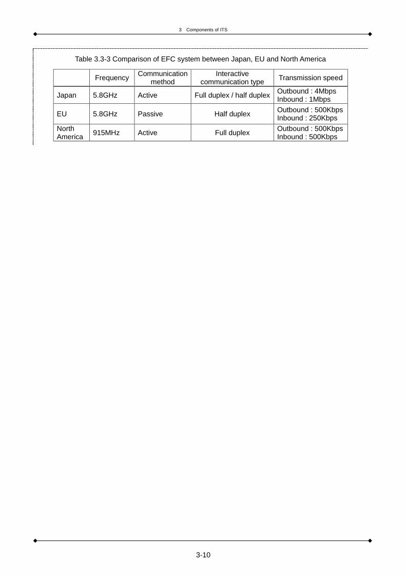
Table 3.3-3 Comparison of EFC system between Japan, EU and North America
Frequency Communication
method Interactive
communication type Transmission speed
Japan 5.8GHz Active Full duplex / half duplex Outbound : 4Mbps Inbound : 1Mbps
EU 5.8GHz Passive Half duplex Outbound : 500Kbps Inbound : 250Kbps
North America
915MHz Active Full duplex Outbound : 500Kbps Inbound : 500Kbps

3 Components of ITS
3-11
[Reference] Overview of ARIB STD-T75 Standard
- ARIB STD-T75 is the standard applicable for EFC and information shower application enlarged
including ARIB STD-T55.
- It is used for current EFC and applicable for other applications. Larger number of channels was saved
by making the frequency half of ARIB STD-T55.
- New channels were added, and 14 channels (7 for inbound, 7for outbound) became available.
Adoption of QPSK and error correction sign enhanced speed and reliability of communication.
- Two-way communication with 4 Mbps is available for 56 vehicles (maximum) in 30m application area.
- It is reflected in ITU-R recommendation 1453 as an international standard.
Table 3.3-4 Overview of ARIB STD-T75 Standard
Access method TDMA-FDD
Frequency 5.8GHz band
TDMA multiplex 8, 4, 2
Number of channel Inbound:7, Outbound:7
Interval of send and receive
frequency 40MHz
Modulation method ASK (Amplitude Shift
Keying)
π/4 shift
DQPSK (Differential Quadrature
Phase Shift Keying)
Transfer speed 1024kbps 4096kbps
Access control method Adaptive slotted ALOHA method
Communication available
speed 180km/h (maximum)
Error correction sign CRC BCH sign
ARIB STD-T85 has been drawn up utilizing the extended communication specification related to DSRC
Application Sub-Layer (ASL) as a standard specification in order to make multiple applications
executable on the DSRC system prescribed in the DSRC system standard, ARIB STD-T75. ARIB
STD-T85 provides a logical structure that makes it easier to use onboard devices and apply them to
business processing systems that have not been targeted, such as applications using the Internet.
[Reference] Overview of Vehicle-to-Vehicle Communication Technology
Vehicle-to-vehicle communication technologies have been trial tested for practical applications in Japan
and the United States, amongst other countries. An example of Japan’s vehicle-to-vehicle
communication technology (ITS FORUM RC-006) is depicted blow.

3 Components of ITS
3-12
[Reference] Overview of Vehicle to Vehicle Communication Technology
A vehicle-to-vehicle communication technology is expected to be deployed to applications relating to
safe driving assist and vehicle operation. However, the challenge is that the positive effects of the
introduction of a vehicle-to-vehicle technology do not appear until the technology becomes widely used
nationwide. This is because they are dependent on the penetration rate of the technology. (The
probability of materialization of communication is proportional to the square of a penetration rate of the
technology.)
- ITS FORUM RC-006 is the guideline which describes the specification of V2V communication system
aimed at safe driving support, by ITS information communication forum.
- It is issued to use 700 MHz effectively, which became available by the analog broadcast end.
- It is aimed at one-way broadcast and being available for hundreds of vehicles.
- Application to safe system is expected because of UFH
- Consideration of effective use is necessary because there is only one available channel.
- Use for V2V communication was expected at first, now use for V2I communication is expected.
Table 3.3-5 Specification of ITS FORUM RC-006
Access method CSMA / CA method
Frequency 720MHz band
Number of channel 1
Modulation method
OFDM
Symbol modulation method BPSK, QPSK, 16QAM
Number of subcarrier wave 52
Effective symbol length 8.0μs
Guard interval length 1.6μs
Occupancy band 8.3MHz
Transfer speed 18Mbps (maximum)
Packet length 1,500octet (maximum)
Frame cycle 100ms or its integral multiple
Error correction Convolutional code with constraint length 7, R=1/2, 3/4
Aerial power 10mW / 1MHz (maximum)
Communication available speed Relative speed between 0km/h and 140 km/h
Source: ITS Forum “Experimental guideline for driving support communication system using 700MHz band”
ARIB STD-T109 is a standard for communication between cars drawn up using ITS FORUM RC-006,
an experiment guideline in the 700 MHz range.
In an environment where there are a lot of cars on the road, access control is required to prevent
packets from sending from these cars simultaneously. Therefore, ARIB STD-T109 uses CSMA/CA, an
access control method used in wireless LAN.
ARIB STD-T109 is a common communication system that time-shares one channel in the 760 MHz
range and operates communication between cars and between a road and a car.
3 Components of ITS
3-13
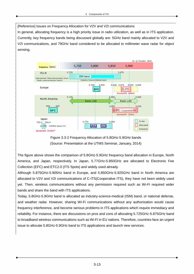
[Reference] Issues on Frequency Allocation for V2V and V2I communications
In general, allocating frequency is a high priority issue in radio utilization, as well as in ITS application.
Currently, key frequency bands being discussed globally are: 5GHz band mainly allocated to V2V and
V2I communications, and 79GHz band considered to be allocated to millimeter wave radar for object
sensing.
Figure 3.3-2 Frequency Allocation of 5.8GHz-5.9GHz bands
(Source: Presentation at the UTMS Seminar, January, 2014)
The figure above shows the comparison of 5.8GHz-5.9GHz frequency band allocation in Europe, North
America, and Japan, respectively. In Japan, 5.77GHz-5.850GHz are allocated to Electronic Fee
Collection (EFC) and ETC2.0 (ITS Spots) and widely used already.
Although 5.875GHz-5.905Hz band in Europe, and 5.850GHz-5.925GHz band in North America are
allocated to V2V and V2I communications of C-ITS(Cooperative ITS), they have not been widely used
yet. Then, wireless communications without any permission required such as Wi-Fi required wider
bands and share the band with ITS applications.
Today, 5.8GHz-5.9GHz band is allocated as industry-science-medical (ISM) band, or national defense,
and weather radar. However, sharing Wi-Fi communications without any authorization would cause
frequency interference, and become serious problems in ITS applications which require immediacy and
reliability. For instance, there are discussions on pros and cons of allocating 5.725GHz-5.875GHz band
to broadband wireless communications such as Wi-Fi in EU nations. Therefore, countries face an urgent
issue to allocate 5.8GHz-5.9GHz band to ITS applications and launch new services.
EFC
EFC

3 Components of ITS
3-14
3.4 Positioning
3.4.1 Necessity for Location Information for ITS
ITS is designed to resolve not only vehicle/traffic issues, such as traffic accidents, traffic congestion and
adverse effects on the environment - but also social issues, such as the aging of population, urban issues,
promotion of tourism, and sustainable economic development.
The fact that ITS is a mobile object (vehicle), rather than a system established in a manufacturing plant or
in an office plays a central role in its potential for success.
The basic structure of ITS consists of five components: sensing, positioning, mapping, communication,
and networking.
In other words, mechanisms for the distribution, storage, and processing of information work
collaboratively to operate a variety of applications by effectively utilizing these five technologies; sensing
technology for collecting information on external circumstances via camera or radar installed on a moving
object or road infrastructures; positioning technology for identifying the location of a moving object;
mapping technology for plotting and displaying the location on a map; communication technology for
linking a moving object to the Center (a base station), as well as a moving object to other moving objects;
and networking technology. (See Table 3.4-1 Driving support applications using map)
In addition, in recent years, increasing importance has been placed on traffic probe information
applications which utilize information collected from a vehicle. As probe information applications require
highly accurate location information, there is a higher requirement for highly accurate location
identification technologies.
3.4.2 Accuracy of Location and Identification Technology Required for ITS
Of all the moving objects, vehicles are operated in a very limited space called a “road.” While airplanes fly
in the air where there are no obstacles and ships cruise on open oceans and seas, vehicles are often
operated in a confined space surrounded by obstacles such as inside tunnels, elevated highways,
underground roads and parking facilities. Despite this, the demand for low-cost location identification
technology is much higher in the case of vehicles compared to airplanes or ships because most of the
vehicles are owned by individuals.
It is because of this high demand that the required specifications of location identification technology in a
vehicle are low cost and the capability to accurately identify location even in a confined space surrounded
by obstacles.

3 Components of ITS
3-15
Table 3.4-2 summarizes the relationship between the accuracy of location information and ITS
applications. In addition, Table 3.4-3 lists the location identification technologies that are now commonly
used.
GNSS is widely used as an ITS application due to cost advantages of roadside units and onboard
equipment. However, GNSS has disadvantages such as the inability to accurately identify location such
as inside tunnels, areas mountainous or surrounded by buildings, to name a few – and it’s susceptible to
error by over a meter. In order to establish an application using relative locations of pedestrians and
vehicles, accuracy of technology in location identification needs to be further improved. Projects to
improve high-precision positioning include EU’s Galileo System, and Japan’s Quasi-Zenith Satellite
System (QZSS). Other approaches to improve positioning accuracy by using correction data from
roadside units are important in positioning at enclosed locations such as tunnels, indoor parking, etc.
where satellite acquisition is difficult.

3 Components of ITS
3-16
Table 3.4-1 Driving support applications using map
Source: ITS Japan next generation digital road information committee
“Report on activities of next generation digital road information committee in 2009”
Static information Dynamic information1) Speed regulation Speed regulation
2) Safe speedInformation onhazardous section
3) Congestion at sagInformation on sagsection, speed
1) Stop section Information on stop
2) One-way lane Information on one-way
1-3. Lane information 1) Driving laneInformation on regulatedlane, changeable lane
Changeable information
1-4. Sign information 1) Sign Sign information1) Congestion Congestion information2) Workzone Workzone information3) Special trafficregulation
Special traffic regulationinformation
1-6. Road surfaceinformation
1) Flooding, freezingFlooding, freezing,weather information
1-7. Zone information 1) Traffic calming zoneInformation on trafficcalming
1) Rain, snow Weather information2) Visibility Visibility information1) Merge Merge section Merge information
2) OvertakeOvertake prohibitedsection
Surrounding vehicleinformation
3) Direction changeDirection changeprohibited section
Surrounding vehicleinformation
4) Oncoming vehicle Road widthOncoming vehicleinformation
5) TramOrbit information,availability of orbit
Tram information
1) StraightDetail information onintersection
Oncoming vehicleinformation
2) Right turnDetail information onintersection
Oncoming vehicle,pedestrian information
3) Left turnDetail information onintersection
Oncoming vehicle,bicycle information
1) ACC (adaptive cruisecontrol)
Gradient of road,curvature
Distance betweenleading vehicle
2) Shift controlGradient and curvatureof road
Roadsurface information
3) Suspension controlGradient and curvatureof road
Roadsurface information
4) Light controlGradient and curvatureof road
5) Stability controlGradient and curvatureof road
Roadsurface information
6) Electric power controlGradient of road, chargearea
Roadsurface information
1) Lane keepLane information(branch, merge section)
Lane information
2) Speed controlregulation speed,dangerous speed
Roadsurface information
3) Stop Information on stop
4) collision avoidance Road shape Roadsurface informationDistance betweenleading vehicle, relative
4-1. Environmentalinformation
1) Reduction of CO2emission
Information on gradientand curvature of roadand speed
Congestion informationFuel consumptioninformation
1) Parking lotParking lot information(location, operating time)
Occupancy, parkinglocation
2) Park and rideParking lot information(location, publictransportation)
Operation of publictransport, occupancy,parking location
3) Multi modalTraffic node information(parking lot, connection)
Operation of publictransport, occupancy,parking location
1. Road informationprovision
TargetsModeMap data
sensor / communication
1-1. Speed information
1-2. Traffic regulationinformation
1-5. Traffic information
1-8. Weather information
2-1. Surrounding vehicleinformation
3-2. Vehicle control
4-2. Traffic nodeinformation
2. Informationprovision onsurroundings
3. Vehicle control
4. Mobility support
2-2. Intersectioninformation
3-1. Vehiclecharacteristics control

3 Components of ITS
3-17
Table 3.4-2 Accuracy of location information required for ITS applications
Accuracy of location
information Relation with road ITS application
±10m Route Route guidance
±1m Inbound / outbound Road information provision (alert)
±0.1m Lane, stop line,
vehicle, human
Safe driving support, vehicle control,
V2V cooperation, V2P cooperation
Table 3.4-3 Comparison of generally used positioning technology
Positioning
technology Accuracy Characteristics
GNSS* ± several
meters
- Recognize position on earth using four GNSS satellites
out of 24 around earth and receiver.
- Cannot recognize position in places where GNSS wave
doesn’t reach such as tunnel.
- High accuracy will be realized by correction using
QZSS (Quasi-Zenith Satellite System)
Mobile base
station
± several
hundred
meters
- Recognize position by ID of base for cell-phone and
PHS and strength of wave from the base.
RFID ± several
centimeters
- Accuracy is high
- Recognize position by reading RFID tag on roadside.
- There is an example of automated driving experiment
using similar method (magnetic nail)
Wireless LAN ± several
meters
- Recognize the position of wireless LAN client by
arriving time and strength of wireless LAN wave.
- Only in the vicinity of wireless LAN base station.
*Technologies for correcting GNSS’s location identification include correction technologies utilizing
ground-based infrastructure beacons, correction technologies utilizing information from dead-reckoning
(DR) sensors, such as compasses, gyroscopes and wheel pulses equipped in onboard unit or vehicles,
and correction technologies using digital road maps.

3 Components of ITS
3-18
[Reference] Highly accurate positioning using the Quasi-Zenith Satellite System
The Quasi-Zenith Satellite Systems is a satellite positioning system developed in Japan, which performs
positioning highly accurately using the same frequency (1575.42 MHz) signal as that of the GNSS and
complementing the GNSS.
The geostationary orbit is a circular orbit looking as if it stopped from the ground because it stays on the
same longitude by moving at the same speed as that of the earth’s rotation. An inclined geostationary
orbit is called the Inclined Geosynchronous Orbit. It forms a figure of eight in the south and north from
the earth. The quasi-zenith orbit is an orbit that can stay longer in the northern hemisphere by making
the inclined geosynchronous orbit elliptical.
1) (1) GNSS compensation
A quasi-zenith satellite can stay for 13 hours in the northern hemisphere. The positioning system is
planned to include three quasi-zenith satellites and one geostationary satellite. Any one of the three
satellites launched to different quasi-zenith orbits is planned to cover areas around the vertex of Japan,
but only one satellite is used now. Though four satellites are required for positioning, it is not uncommon
to have less than four satellites on the LOS (line of sight) between buildings. As one more satellite of
LOS can ensure they are in the vertex, positioning between buildings can be improved.
Even a signal from a LOS satellite has an error in the quasi-distance due to multiple paths. However, a
satellite with a higher elevation angle can emit an electric wave which then reflects a wave that more
easily reaches near a building, than one with a lower elevation angle. This means that in the centre of a
road distant from a building, a signal from a satellite with a higher elevation angle like a quasi-zenith
satellite is insulated from the influence of multiple paths - and less influenced by positioning of a car
navigation system. A quasi-zenith satellite stays around the vertex in Japan and Australia while it does
not appear in South-East Asian countries but it can ensure its significance of existence as a satellite with
a higher elevation angle.
2) (2) GNSS reinforcement
As a signal of a GNSS is sent from space of 20,000 km or more above the ground, it is faint. An electric
wave is difficult to reach and has an error due to the influence of various natural environments, surface
topography, and ambient radio wave environments. GNSS reinforcement aims at realizing highly
accurate positioning by giving a quasi-zenith satellite’s original reinforcement information. A quasi-zenith
satellite is expected to provide highly accurate positioning anywhere nationwide as it sends an
unaffected signal from directly above.

3 Components of ITS
3-19
3.5 Mapping
Positional data need to be associated with map data. Obtaining positional data alone would not provide
the location of a moving object, or route search function unless positional data are linked with map data. A
number of map data are required for ITS: base map data, road network data (link/node), and information
on the above data connected, road characteristics data (traffic restriction, stop line, sidewalk, interchange,
etc.), static information (landmark, warning, etc.), and dynamic information (traffic restriction, road surface,
weather, etc.). These data turn into useful information to drivers through applications such as route search.
Therefore, completeness, accuracy, and “freshness” are required for data in each application. In particular,
freshness is critical in map data for user convenience. A method to keep the map as up-to-date as
possible with information which is renewed every day is the key. If a route search application does not
recognize a newly opened road section, the service would not be provided to users. How to update map
data is fundamental in ITS application.
The concept of Dynamic Map in terms of international standards, currently under discussion, is a
mechanism to build a map overlaid with static information such as landmark, and dynamic information
such as local information and traffic signal. In order to realize driving support service, systems of linking
the base map with static, quasi-static, quasi-dynamic, and dynamic data is essential.
Figure 3.5-1 Concept of Dynamic Map
(Source: SIP-adus)
• ITS forecast information
(information on nearby vehicle &
pedestrian, traffic signal, etc.)
• Information on accident, congestion,
local weather forecast, etc.
• Information on traffic regulation, road
work, weather forecast for wide area
• Information on road surface, traffic
lane, 3D structure, etc.

3 Components of ITS
3-20
3.6 Sensing
3.6.1 Sensing Technology for Further Improving Traffic Efficiency
In order to further improve traffic efficiency, it is important to fully understand the mechanism of traffic
congestion and detect the causal factors of the congestion.
Traffic congestion is expressed by traffic flow rate (q) and average speed of traffic flow (v), and it is
important to understand the status of these factors.
Figure 3.6-1 Relation between traffic flow ratio (q) and average speed (v)
(1) Sensing Technology for Measuring Average Speed of Traffic Flow (v)
A variety of sensors have been developed and put to use for the purpose of measuring the average speed
of traffic flow. The representative types of such sensors are shown as follows:
Table 3.6-1 Average speed sensing technology
Technology Ultrasonic wave sensor Image processing Optical beacon
Outline
- Sensor set downward
from gantry, or
sideways from roadside
- Read license plates
for travel time
between two points
- From travel time
between two points
(by acquiring ID with
optical beacon)
Disadvantage - Machinery malfunction
and maintenance
- Low accuracy in
night-time and bad
weather
- Necessity for OBUs to
be accommodated
Remarks - Widely used in EU and
US
- Widely used in
Japan - Widely used in Japan
*In addition to the above, a technology for measuring the average speed of traffic flow by using a probe
car data is also available (provided that, if probe car data are not widely used, the frequency of such
measurement may be low).
Free flow
Critical flow
Congested
flow

3 Components of ITS
3-21
(2) Sensing Technology for Measuring Traffic Flow Rate (q)
Techniques for measuring traffic flow rate are roughly outlined as follows:
Table 3.6-2 Traffic flow ratio sensing technology
Technology Loop coil Ultrasonic wave sensor Image processing
Outline
- Embedded coils in
road surface to
detect moving metal
- Sensor set downward
from gantry, or sideways
from roadside
- Recognize movement
and number of vehicles
by image
Disadvantage
- Machinery
malfunction and
maintenance
- Machinery malfunction
and maintenance
- High cost due to gantry
and sensor in each lane
- Not being able to detect
vehicles out of lanes
- Low accuracy in
night-time and bad
weather
Remarks - Widely used in EU and
US
- Multiple lanes can be
measured at the same
time.
- There is no restriction
of installing over the
lanes
A sensing technology using a space-time Markov Random Field (MRF) model is taken up as an example
of image sensors. A space-time MRF model is a technology that performs sensing by putting a regional
division in place in a block of eight pixels by eight pixels as one unit and by defining a correlation in the
time axis direction that refers to the motion vector per each block between image frames. By using this
technology, it is possible to obtain a variety of traffic statistics, including traffic flow rate (q) and average
speed of traffic flow (v) without being affected by changes in lighting intensity and the shadow of buildings,
among other things.
Figure 3.6-2 Conceptual diagram of time-space MRF model and an example of sensing
(a) Tracking against occlusion
(b) Tracking in building shadow

3 Components of ITS
3-22

4 Applications
4-1
4. Applications

4 Applications
4-2
4.1 Traffic Control
4.1.1 Content of Application
On urban and inter-city expressways, the occurrence of events such as traffic congestion, traffic accidents,
abnormal weather and disasters poses a problem in ensuring the safety of road users and smooth traffic
flow.
The purpose of a traffic control system is to ensure the safety of road users and smooth traffic flow. This
is done by collecting information concerning a variety of events that occur on roads and the resultant road
conditions, traffic conditions and weather conditions – and then processing and providing such
information to road users in a prompt and proper manner.
4.1.2 Configuration of Traffic Control System
A traffic control system largely consists of (i) information collection infrastructure, (ii)
information-processing infrastructure, (iii) information provision infrastructure, (iv) communications
infrastructure, and (v) monitoring infrastructure. In addition to the above infrastructures, disaster
prevention infrastructure may be included if there are structures that need to be monitored, such as
tunnels.
(i) Information Collection Systems
The information collection infrastructure collects information on traffic conditions, weather conditions, etc.
As for the method of collecting information on traffic conditions, a vehicle detector is employed in many
cases for collecting information on traffic volume, speed, and occupancy levels. The following
infrastructure have come to be used more often in recent years: probe cars capable of continuously
collecting information on traffic conditions, imaging sensors capable of detecting unexpected incidents
(such as sudden deceleration, traffic accident and falling objects), and license plate readers capable of
directly measuring required travel times,. As a side note, the method for collecting information on required
travel times by utilizing EFC’s information on time when a vehicle passes through a tollgate has been put
to practical use in Japan.
In addition, it is recommended to install weather sensors such as rain gauges to cope with the spate of
recent “guerrilla rainstorms” (localized torrential rains), and flood meters in locations that tends to be
submerged by floods, such as underpasses.
It is possible to promptly obtain information on disabled vehicles or falling objects on roads by installing
emergency telephones and CCTV monitors at regular intervals along roads.
Furthermore, in order to optimally control the entire road network, it is recommended to collect information
on adjacent expressways and ordinary roads that run parallel to expressways, from other road managers.

4 Applications
4-3
(ii) Information-processing Systems
The information-processing infrastructure processes a vast amount of information provided by the
information collection infrastructure, evaluates the levels of traffic congestion, prioritizes information that
needs to be provided to the information provision infrastructure, and processes the content of information
to be provided.
In recent years, systems have been developed to provide road users with information on projected traffic
conditions by analyzing real-time traffic conditions and past trend data. On the metropolitan expressways
in Japan, a road information board displays not only information on traffic congestion (such as
traffic-congested zones and length of traffic congestion) but also information on trends in changes in
traffic congestion.
(iii) Information Provision Systems
The information provision infrastructure provides information processed by the information-processing
infrastructure to road users.
Road information boards and highway radio applications are commonly used as the information provision
infrastructure. A road information board provides more specific information, such as information on areas
where there is traffic congestion or traffic is regulated and the length of traffic congestion. If there are
wide-area detour routes available to avoid traffic congestion, it is recommended that a graphic road
information board be installed to provide road users with information that enables them to visually
understand traffic conditions and available alternative routes and decide on optimal routes which suit
them.
Currently, information for personal computer (PC) compatible or Internet-compatible mobile phones and
smartphones is also provided to road users via the Internet. In addition, it is possible to provide more
detailed information to road users by installing a large display road information board or an interactive
road information kiosk in expressway rest areas, which is a computer terminal that provides road
information to road users.
In Japan, road-to-vehicle communication systems such as IVI or ITS Spot are utilized as a means of
providing information to road users while they are driving. This information includes wide-area roads and
comparisons on the number of available routes, amongst other information. It is recommended this
information be provided to road users to assist in their effective use of road networks.
(iv) Communications Systems
The communications infrastructure connects the information collection infrastructure and the information
provision infrastructure, both of which are installed roadside, to the information-processing infrastructure,
which is installed at a road manager’s traffic control center or similar.
In Japan, such a connection is often made via wire communication (optical fiber or exclusive line). In
recent years, optical fibers have been more extensively used because they are superior in terms of
communication capacity and scalability.
4 Applications
4-4
In cases where roads are newly constructed, it is more efficient to install the communications
infrastructure concurrently.
If it is difficult to newly install a wired communication network for costs and other reasons, it is possible to
use an Internet connection as a virtual private network (VPN) connection or use radio communication
networks, provided that, as such methods are inferior to an exclusive wired communication line in terms of
reliability, it is necessary to fully compare and review all the available methods.
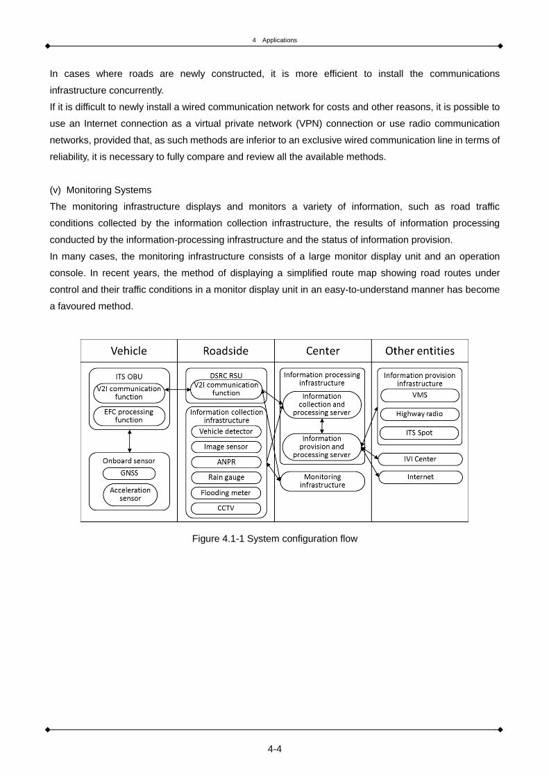
(v) Monitoring Systems
The monitoring infrastructure displays and monitors a variety of information, such as road traffic
conditions collected by the information collection infrastructure, the results of information processing
conducted by the information-processing infrastructure and the status of information provision.
In many cases, the monitoring infrastructure consists of a large monitor display unit and an operation
console. In recent years, the method of displaying a simplified route map showing road routes under
control and their traffic conditions in a monitor display unit in an easy-to-understand manner has become
a favoured method.
Figure 4.1-1 System configuration flow

4 Applications
4-5
Figure 4.1-2 The whole image of the technology related to ITS

4 Applications
4-6
[Reference] Example of Traffic Control System
Expressway companies are monitoring the traffic situation of expressways for safe, secure, and
comfortable driving and are evaluating a variety of equipment necessary for traffic control 24 hours a
day. Figure 4.1-3 shows the example of traffic control center of Central Nippon Expressway Company
Limited.
Figure 4.1-3 An example of traffic control center
(Source: Central Nippon Expressway Company Limited)
Traffic control and facilities control
水噴霧設備
From users Central NEXCO collects
Information acquisitionTraffic control Facilities control
Un
de
rsta
nd
ing
of
situ
atio
n &
de
cisi
on
Initial countermeasuresInformation
provisionMonitoring and
control of facilities
Road control center

4 Applications
4-7
[Reference] Active Traffic Management (ATM) in the UK
Chronic traffic congestion to the tune of 120,000-plus cars occurs every day on the M42 near
Birmingham in the UK. Active Traffic Management (ATM) was introduced on road sections of 17km in
2006 in an attempt to combat this problem.
ATM aims at alleviating traffic and improving safety by actively managing traffic. It does this by using
information technology such as changing regulatory speeds and opening berms to general drivers
according to traffic.
In a normal traffic situation, if nothing is displayed on the variable information sign, the speed is limited
to 70 mph (approximately 110 km/h) and berms are available only in the case of emergency.
When the system confirms congestion, the vehicle detection loop and CCTV in the control room informs
drivers of countermeasures on the variable information board. First, “congestion alert” and “accident
alert” are displayed. Then the speed limit and lane closure are displayed.
As congestion and accidents increase traffic, berms are used for general traffic. When the closure
information on the variable information board disappears, the speed limit is displayed for drivers.
Figure 4.1-4 Active Traffic Management (ATM) on M42

4 Applications
4-8
4.2 Traffic Signal Control
4.2.1 Content of Application
In large city areas where traffic congestion has become very serious, it is possible to increase the
efficiency of traffic flow by adopting more sophisticated signal control systems to help alleviate traffic
congestion.
For methods of traffic signal control, a coordinated signal control system is commonly used. This system
defines main roads as primary roads and roads that intersect with primary roads as subordinate roads;
traffic on primary roads is then controlled on a priority basis. Studies are currently underway on a network
signal control system which aims to optimize traffic flow across the entire road network through the further
sophistication of coordinated signal control.
Figure 4.2-1 Conceptual diagram of network control
(Source: S. Kamijo, Sensing technology for making traffic efficient)
It is also possible to perform more sophisticated signal control functions by using real time traffic data
such as traffic volume, occupancy rate and queue length (see the next page).
A vehicle detector, which is installed on the upstream section of a traffic signal, is commonly used to
collect information on traffic volume, occupancy rate, etc.
Road network
Control
parameters
Sub area
C: cycle, S: split, O: Offset, j: Joint link
Link t Node n

4 Applications
4-9
Table 4.2-1 Classification of Traffic Signal Control by Generation and Key Input Data
Gene-
ration
Designed control
contents
Control design Control Systems abroad
1 Traffic volume Designed off-line Fixed time control
1.5 Traffic volume/
Occupancy
Designed off-line,
but use data of
detectors
Pattern selection with
unit time data
SCATS
(split, offset)
2 Traffic volume/
occupancy/
vehicles in queen/
degree of saturation
Online generated Compute per time unit
with time unit data
SCATS (cycle)
SCOOT (cycle)
2.5 All of the above, and
estimated time of arrival
(detector -> stop line)
Online generated Calculate estimated
delay per second
(cycle/
signal indication)
SCATS
(split, offset)
MOVA
(isolated
intersection)
3 All of the above, and
forecasted time of arrival
Online generated Calculate forecasted
delay of 1 – 2 minutes
ahead per 3 – 5
minutes
OPAC (US)
PRODYN
(France)
UTOPIA (Italy)
Source: Japan Society of Traffic Engineers, Revision of manual for traffic signal
4.2.2 System Configuration
In order to further advance traffic signal control and obtain a more detailed understanding of the traffic
data, the following methods can be utilized (in addition to an existing vehicle detector): (i) installation of
new sensors at intersections (utilization of imaging sensors, etc., for the collection of data, such as inflow
traffic volume, outflow traffic volume and bifurcating traffic volume by direction) and (ii) utilization of probe
car data for the collection of data on vehicle speed and queue length.
Through the installation of new sensors at intersections by utilizing probe car data, traffic signal control
could be sophisticated. By assuming inflow traffic volume and queue length as the amount of vehicular
traffic demand, it is possible to determine the cycle length that is required to cope with such vehicular
traffic demand and the distribution of traffic signal splits. It is also possible to determine optimal offsets
between intersections based on vehicle speed data obtained from probe car data.
In order to enhance the reliability (real-timeliness) of data on vehicle speed and queue length from probe
car data, it is necessary to secure a sufficient number of vehicles fitted with probe devices.

4 Applications
4-10
Figure 4.2-2 System configuration flow

4 Applications
4-11
[Reference] Example of Traffic Signal Control and Traffic Control Systems in Japan
In Japan, a traffic control system that is capable of controlling all traffic conditions from under-saturation
to over-saturation has been realized by implementing either macro or micro control, or both macro and
micro controls in combination, depending on traffic conditions.
In Japan, signal control is performed by using sensors that are installed roadside at close intervals. In
countries or cities where the number of existing roadside sensors is small, it is possible to realize more
sophisticated signal control by introducing probe car data that is capable of measuring both the length of
traffic congestion and vehicle speed as well as utilizing data obtained from probe car data for signal
control.
Figure 4.2-3 Image of the system using Japanese style traffic signal control and traffic control
一般道
交通管制センター
センサ情報
信号制御
渋滞長計測
信号制御
センサ情
報
上流の交通情報
プローブ情報
Arterial road
Traffic control center
●Macro control
“MODERATO”
- Japanese unique method of measuring congestion length
- Execute suitable control continuously based on congestion length in addition to traffic volume
●Micro control “Profile traffic signal control” changed from “Sensitive control”
- Control traffic signal finely based on the traffic volume of the upstream
- Correspond to rapid change in traffic volume
- Function individually without traffic control center

4 Applications
4-12
[Reference] Representative Traffic Signal Control Technologies
A variety of traffic signal control systems have been developed in many countries of the world. The three
most well-known traffic signal control systems in the world are Australia’s Sydney Coordinated Adaptive
Traffic Systems (SCATS), the United Kingdom’s Split Cycle Offset Optimization Technique (SCOOT),
and Japan’s Management by Origin-Destination Related Adaptation for Traffic Optimization
(MODERATO).
(1) SCATS
In SCATS, the basics of signal control are the optimization of splits at a single intersection. The degree of
saturation (DS) is used as a parameter, and splits are controlled according to the rate of DS of
intersecting traffic flows. In SCATS, loop detectors are installed in front of the stop line of an intersection,
and DS values are calculated based on the ratio of ON-OFF time of these loop detectors. In the following
figures, thick lines represent the ON state, in which a loop detector detects a vehicle.
(a) Detector installation in SCATS
(b) Concept of Loop Detection
Figure 4.2-4 Traffic Flow Measurement Method in SCATS
Broadly speaking, the time when a loop detector is ON is short when traffic is light, while it is long when a
vehicle queue is generated by traffic congestion.
Detector installed area
g second
Saturated flow
Unsaturated flow
Congestion due
to traffic ahead
t second

4 Applications
4-13
The number of passing vehicles and the inter-vehicle time are measured immediately before the stop
line. This will not only directly measure the level of congestion at an intersection but also facilitate system
control by consolidating measuring sensors near an intersection. SCATS has been adopted in many
countries in Asia because of its simplicity. Loop detectors are commonly used for SCATS but their main
disadvantage is the high cost of installation and repair. Going forward, it is important to try to reduce the
cost of installation and repair by adopting imaging sensors, etc.
(2) SCOOT
SCOOT’s main characteristic works by optimizing offsets by predicting vehicle arrival profiles. For this
reason, in the case of SCOOT, it is desirable to install detectors upstream from the average queue length
at a traffic light. In fact, in many cases, detectors are installed on the upstream side and at locations
about 20 meters from the exit of an intersection.
Figure 4.2-5 Detector installation in SCOOT
(3) MODERATO
MODERATO, an index that utilizes the number of vehicles queued at an intersection, is used as DS. This
is in addition to the inflow traffic volume into an intersection as used in SCOOT. As there is heavy traffic
congestion in Japan, DS is weighted by the demand of vehicles in queue at an intersection. It is not
unusual in Japan for the length of traffic congestion to extend past one kilometre. Because of this,
sensors are installed for more than one kilometre at an interval of several hundred meters from a critical
intersection where traffic congestion is heavy.
SCATS, which is designed primarily for traffic signal control for a single intersection, is designed to
control offsets by selecting patters according to traffic volume. Thus, it looks like offsets are controlled on
an after-the-fact basis. In contrast, SCOOT is a strategy that is intended to allow arriving vehicles to pass
through an intersection in the most efficient manner by preparing vehicle arrival profiles, and it forms the
basis of today’s coordinated signal control systems. In MODERATO, which is based on SCATS, the
length of congestion is factored into DS with the aim of reducing lengthy and heavy traffic congestion
that originates from congestion at a critical intersection where main roads cross each other.
Detector installed area

4 Applications
4-14
4.3 Electronic Fee and Toll Collection (EFC) System
4.3.1 Toll System
There are two methods of Electronic Fee Collections (EFC): DSRC and autonomous methods. DSRC
charges tolls using vehicle to infrastructure communications between roadside antennas and onboard
units. Autonomous method charge tolls by onboard unit by acquire its own location based on information
through Global Navigation Satellite System (GNSS).
DSRC method has advantages of high accuracy, making fraud difficult, as well as not requiring
communication costs. However, it requires furnishing facility at every location for tolling, and thus, it is not
suitable for having numerous tolling points or for toll roads that often change tolled sections.
Autonomous toll method has advantages of changing setting flexibly such as distant based toll. However,
it would require roadside facility to regulate and control fraud. It also requires high communication costs.
4.3.2 Service Contents
EFC with DSRC is a system designed to manage the entry of vehicles to a toll road as well as processing
the payment of tolls by utilizing radio communications between the EFC onboard unit of passing vehicles
and a roadside system. EFC users can enter a toll road without having to stop at a toll gate. With the use
of EFC, it is also possible to offer EFC users a mileage bonus program that is based on the amount of tolls
paid (reward points are given to EFC users for the amount of tolls paid and when a certain level of reward
points is accumulated, they can be used to pay a part of tolls.)
In addition, it is expected that the use of the EFC toll payment processing system using DSRC will be
expanded to serve as a multipurpose payment processing system, such as for processing payments at
parking facilities and gasoline stations. DSRC, which is suitable for use for free-flow systems (payment of
tolls using radio communication devices installed alongside a toll road), is capable of coping with a wide
variety of charging methods.
Figure 4.3-1 Image of EFC system

4 Applications
4-15
Table 4.3-1 Contents of each application
Application Contents Payment process - Automatically collect tolls based on travel distance or flat rate
system at barriers of toll road
- Correspond to discount process such as time-based discount
Mileage - Issue points based on the fee
- Toll can be discounted depending on the accumulated points
4.3.3 System Configuration
DSRC EFC consists of roadside antennas, roadside units, in-vehicle onboard unit, and Integrated Circuit
(IC) cards.
Information about the tolls is exchanged at the entrance or exit of a toll road via two-way radio
communications between vehicles and roads using active DSRC in the 5.8 GHz band, and tolls are
charged according to the distance traveled. Depending on its system configuration, EFC is also capable
of being flexible, coping with a variety of toll collection methods, such as distance-based pricing, flat rate
pricing, time-based discount pricing, and long distance travel discount pricing.
Figure 4.3-2 Mechanism of DSRC EFC (Source: ITS Handbook)

4 Applications
4-16
Figure 4.3-3 System configuration flow
In the case of EFC, a Radio Frequency Identification (RFID) tag system is made available in addition to an
active system and a passive system. The comparison of different EFC systems is shown in the table
below. It is recommended that, as there are advantages and disadvantages in each of these EFC systems,
the adoption of an EFC system be studied carefully, taking future scalability into consideration.
4.3.4 Expanded services
The autonomous EFC serves to charge tolls on motorists but it is also used as a platform for a wide range
of ITS services thanks to the sophisticated functions embedded in onboard devices, including seamless
self-positioning, communication with the centre system and driver interface.
Examples of these services are provided below. An autonomous EFC is generally superior to a
smartphone in position orientation accuracy and device reliability with the ability to solve regional road
traffic problems and wide commercial applicability.
(1) Traffic Management
Meticulous traffic information (vehicle position, speed, origin and destination, etc.) is compiled from
onboard devices and analyzed to formulate, regulate and guide road planning.
(2) Travel/Traffic Information
Traffic and congestion information is relayed to the driver and optimal routes that avoid jams are provided.
(3) Public Transport Information
Bus operation conditions are assessed and communicated to users and controls such as departure
increases and route changes.
(4) Taxi Dispatch
A taxi dispatch system utilizing onboard devices and communication infrastructure to facilitate dialogue
between users, taxi managers and drivers.
(5) Fleet Management
Truck and other commercial vehicle operation conditions are assessed to facilitate scheduling.
Vehicle Roadside Center Other entities
EFC OBE
V2I communication function
EFC card
DSRC RSUV2I communication
function
Gate bar
Toll display
TV camera
EFC processing function
Roadside infrastructure
Payment processing server
Mileage point control server
Control infrastructure
ID control server
Credit payment system
Backyard system

4 Applications
4-17
[Reference] The Image of the Processing of the Payment of Tolls on Toll Roads (where tolls vary
according to the distance travelled)
The comparison of the processing of the payment of tolls by onboard unit and the Centre (using a
read-only RFID system, etc.) is shown below. If tolls are processed by the Centre, there is a heavier
burden on the Centre. This means the Centre must be highly reliable, as all relevant data collected
both at the entrance and exit of a toll road must be sent to there and then consolidated by the Centre
itself. In addition, the relevant communication network must be highly reliable as there is an exchange
of data between the Centre and roadside infrastructures.
Alternatively, if tolls are processed by onboard unit, there is less of a burden on the Centre. With the
charging and payment of tolls processed by onboard unit and a roadside unit, the Centre is only
processing the settlement of tolls with card issuers.
1) When Payment of Tolls Is Processed by Onboard unit
Figure 4.3-4 Image of payment processing with OBU
2) When Payment of Tolls Are Processed by the Center (using RFID system)
Figure 4.3-5 Image of payment processing at the Center
OBU
IC card
RSU
Input of entrance data
RSU
OBU
IC card
Load of entrance data
Charge
Payment
Road administrator Central unit
Payment data
Financial institutions
Charge, pay
RFID
RSU
Entrance data(OBU-ID, etc.)
Road administrator Central unit
Charge, pay
RFID
RSU
■Payment process ・Verification process (Entrance, exit, OBU-ID) ・Payment
Financial institutions

4 Applications
4-18
[Reference] Examples of utilization of EFC Systems (utilization of EFC systems as smart IC systems,
etc.)
As it is possible to simplify a toll gate structure and eliminate toll collectors by utilizing DSRC EFC
systems, it is therefore possible to establish toll road interchange or entrance/exit facilities at lower costs
in a more flexible manner than those previously installed.
The installation of smart IC systems has already progressed in Japan and produced positive results. It
has alleviated traffic congestion, reduced travel time on ordinary roads, revitalized local economies and
reduced the response time of emergency vehicles.
Example of smart IC
Figure 4.3-6 Example of smart IC (Miyoshi smart IC in Kanetsu Expressway) (Source: MLIT)
Example of Toll Road Exit for Ambulances
Figure 4.3-7 Example of Toll Road Exit for Ambulances

4 Applications
4-19
[Reference] ERP (Electronic Road Pricing)
Singapore has a road pricing system in place that controls traffic flow through its extremely congested
Central Business District (CBD) by charging any vehicle that ventures in. In 1975, it adopted a manual
road pricing system where police officers visually verified stickers affixed to vehicle windshields - but
they quickly realized that purchasing those stickers was burdensome and surveillance costs were high.
Planners ended up looking for a more flexible means of controlling traffic. The introduction of a new
electronic fully automated ERP system resolved these issues.
Figure 4.3-8 Road Pricing prior to ERP Introduction
Figure 4.3-9 ERP Overview
Because ERP is a completely electronic multi-lane free flow system, overall costs are low and there is
no need for acceleration and slowing down at tolling areas making it both environmentally and user
friendly. A focus on the development of applications other than road pricing at the onset of system
conceptualization led to the adoption of a two-piece on-board device in which a prepaid IC card is
inserted. The system is completely unmanned with cameras installed on gantries photographing any
vehicle without an ERP device mounted on-board. Any driver who may have forgotten to prepay their
cards is sent a bill demanding the payment of a penalty fee automatically. Not long after ERP’s
inception, data showed a decline in traffic of approximately 20%.
As mentioned in item 3.4.3, the characteristics of ERP has realized services above and beyond mere
road pricing, that are both flexible and varied to an extent not experienced anywhere else in the world.

4 Applications
4-20
ERP is composed of antennas, vehicle detectors, surveillance cameras and lights mounted atop
gantries, devices installed in vehicles, IC cards and central computers. Tolls are determined by gantry
location, day of the week, time of day, and type of vehicle. Displays mounted on the gantry show the toll
amount, which can be visually checked by the driver when passing through. The on-board devices and
antennas passively communicate in the 2.45 GHz band. Another feature is that almost all vehicles in
Singapore are equipped with ERP devices.
Figure 4.3-10 Overview of ERP System Equipment
Table 4.3-2 ERP Onboard Unit Standards
Radio frequency 2.45GHz
Radio system Passive system (homodyne detection)
Throughput Down:56kbps
Up:124kbps
Card standards ISO7816
ISO14443 Type B*
Temperature 0°C - + 85°C
*Card standards for Second generation OBU using Contactless IC card system

4 Applications
4-21
[Reference] Autonomous EFC
Unlike DSRC, Autonomous EFC system, onboard devices acquire their own positions on the road
based on signals received from GNSS satellites. Moreover, those devices communicate with centre
systems to report positioning and tolling information and update stored data.
A feature of this system is the lack of any significant roadside unit; however, in the interest of fairness,
certain equipment is necessary for disciplinary purposes. For example, vehicles on a toll road without a
device installed onboard are photographed and charged a penalty fee. Equipment to regulate motorists
can be set up independently from tolling locations. For example, roadside infrastructure can be
constructed on major roads, whilst in other areas, mobile regulatory systems can be mounted in
vehicles to reduce costs, while maintaining maximum effect.
Figure 4.3-11 Standard configuration of an autonomous EFC
(1) Germany and Slovakia's highway heavy vehicle tolling
In Germany, an automated tolling system for heavy vehicles of 12 tons or more operating on the
Autobahn was launched in 2005. It was later expanded to impose toll charges on some federal roads,
after trucks deviating on alternate routes to avoid tolling created congestion. In the summer of 2015, the
system began tolling vehicles weighing 7.5 t or more. By 2018, all federal roads will be subject to tolling.
Slovakia's primary national highways and some regular roads began tolling heavy vehicles (3.5 t or
more) with an automated system in 2010.

4 Applications
4-22
(2) Singapore's next-gen ERP
While its DSRC-type ERP has already been introduced to alleviate downtown congestion, the city and
state plans to update it by switching to an automated tolling system. Planners want more accuracy than
the autonomous EFC projects being developed in Europe, enabling them better positioning among
Singapore's many buildings and tunnels and its particular road structure. They will also add multiple new
functions to enhance motorist convenience such as traffic information transmissions and parking fee
charging. Launch is scheduled for about 2020.
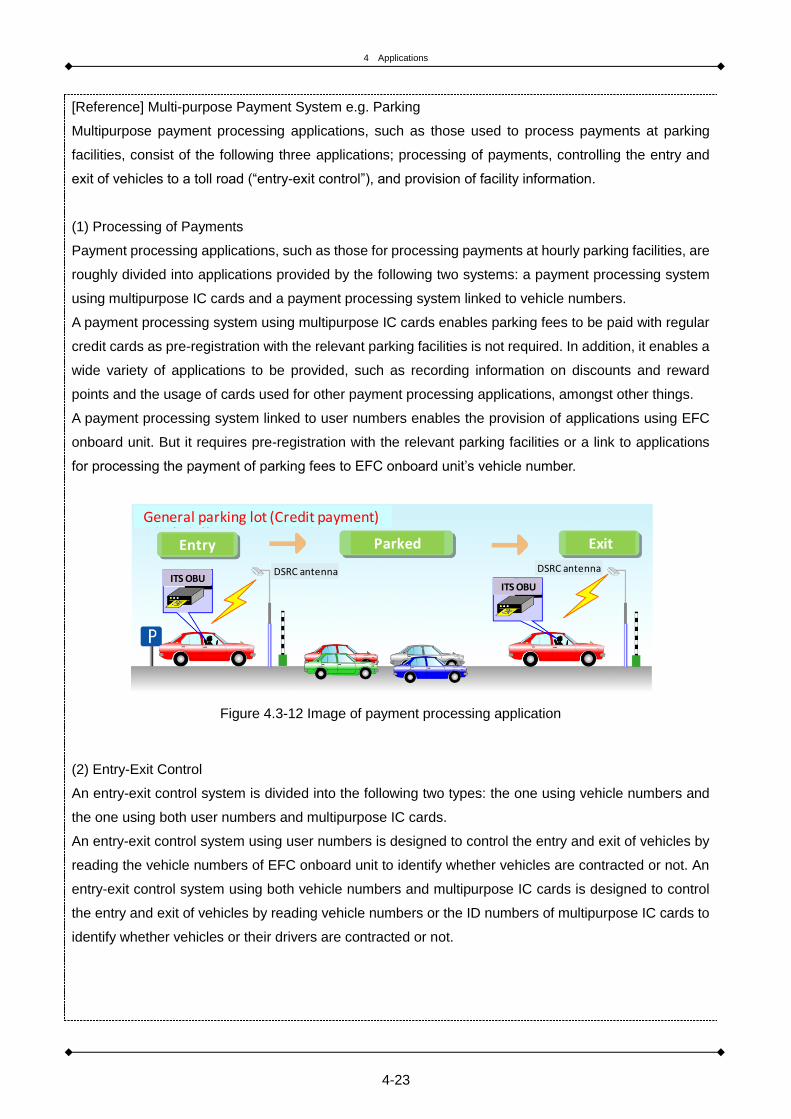
4 Applications
4-23
[Reference] Multi-purpose Payment System e.g. Parking
Multipurpose payment processing applications, such as those used to process payments at parking
facilities, consist of the following three applications; processing of payments, controlling the entry and
exit of vehicles to a toll road (“entry-exit control”), and provision of facility information.
(1) Processing of Payments
Payment processing applications, such as those for processing payments at hourly parking facilities, are
roughly divided into applications provided by the following two systems: a payment processing system
using multipurpose IC cards and a payment processing system linked to vehicle numbers.
A payment processing system using multipurpose IC cards enables parking fees to be paid with regular
credit cards as pre-registration with the relevant parking facilities is not required. In addition, it enables a
wide variety of applications to be provided, such as recording information on discounts and reward
points and the usage of cards used for other payment processing applications, amongst other things.
A payment processing system linked to user numbers enables the provision of applications using EFC
onboard unit. But it requires pre-registration with the relevant parking facilities or a link to applications
for processing the payment of parking fees to EFC onboard unit’s vehicle number.
Figure 4.3-12 Image of payment processing application
(2) Entry-Exit Control
An entry-exit control system is divided into the following two types: the one using vehicle numbers and
the one using both user numbers and multipurpose IC cards.
An entry-exit control system using user numbers is designed to control the entry and exit of vehicles by
reading the vehicle numbers of EFC onboard unit to identify whether vehicles are contracted or not. An
entry-exit control system using both vehicle numbers and multipurpose IC cards is designed to control
the entry and exit of vehicles by reading vehicle numbers or the ID numbers of multipurpose IC cards to
identify whether vehicles or their drivers are contracted or not.
ITS ITS
General parking lot (Credit payment)
Entry Parked Exit
ITS OBUITS OBU
DSRC antenna DSRC antenna

4 Applications
4-24
(3) Provision of Facility Information
Information regarding facilities like designated parking spaces for the handicapped, an overview of
facilities, the usage of parking facilities, etc., is provided to ITS onboard unit in the form of text, voice
commands or still image, via push-type information distribution systems.

4 Applications
4-25
[Reference] Examples of Application Introduction
■ Introduction of parking fee settlement systems in Japan
Machikado (Street Corner) e-Applications (Hanshin Expressway Company Limited)
*Payment of parking fees can be automatically processed by using EFC at toll parking facilities.
(Implementation period: May 2008 to August 2014)
Off-Expressway Parking Applications (Hanshin Expressway Company Limited)
*The applications enable a user to pay the “through toll” by using EFC even when he/she exits an
expressway once, uses off-street parking facilities, and then re-enters an expressway again.
(Implementation period: February 2009 - ongoing)
Times’ EFC Applications (Times 24. Co., Ltd.)
*The EFC system can also handle affiliated applications (applications of providing discounts when
using affiliated commercial facilities).
Figure 4.3-13 Example of Off-Expressway Parking Applications
Source: Hanshin Expressway Company Limited

4 Applications
4-26
■ Introduction of a parking fee settlement system in Singapore
There are about 3,000 cashless parking lots all over the island constituting the EPS (Electronic Parking
System). Driver stress is greatly reduced as there is no need to stop or open and close the window
when entering or exiting a lot. Because the gate is managed by the host computer, parking fees can be
set at any random time making it a very advantageous system for the parking lot manager.
a) Gate b) System configuration
Figure 4.3-14 EPS (Electronic Parking System)
Compatibility with commuter cards began with the advent of 2nd generation onboard devices which had
their range of services upgraded in 2009. These can function with contactless IC card systems. Prior to
that was the incompatible first-gen onboard devices of the contact-type IC card system.
Antenna

4 Applications
4-27
4.4 Probe car data collection
4.4.1 Contents of application
Probe car data collection is designed to monitor the operations of vehicles by obtaining information on
vehicle ID, etc., from passing vehicles via DSRC roadside radio communication equipment.
In the past, the main method for collecting road traffic information was to collect spot data using roadside
detectors, and CCTV cameras but the utilization of DSRC or mobile phones for traffic data collection has
made it possible to upload probe car data from buses, taxis and ordinary vehicles. A mobile phone is
suitable for collecting data from buses and taxis on a real-time basis but the disadvantage of using a
mobile phone for this purpose is that a user has to bear the relevant communication costs. On the other
hand, DSRC is not suitable for collecting information on a real-time basis, but its advantages is that
communication costs are free – and it can share information with EFC, amongst other things.
Probe car systems have made it possible to obtain sequential traffic data and it is expected that the use of
probe car data systems will be further expanded to include the provision of a variety of applications, such
as traffic control, road management, and bus location systems.
Figure 4.4-1 Image of probe car data collection
Probe car data collection is provided by the five information collection related applications shown in Table
4.4-1. These applications are used for the collection of information on vehicle ID, time and location,
weather and vehicle behaviours, amongst other things.

4 Applications
4-28
Table 4.4-1 Contents of application
Application Contents
Collection of vehicle ID - Vehicle ID
Collection of travel history - Information on time and location
Collection of detailed travel history
- Information on speed, direction, acceleration, and angular velocity
Collection of vehicle control information
- Information on outside temperature, wiper operation, ABS operation, traction control
Collection of operation information
- Information on vehicle, bus usage, freight vehicle, oversized vehicle, hazardous material vehicle information
4.4.2 System Configuration
The basic system configuration as described below is used for collecting road traffic information using
probe car data.
A network for the collection of road traffic information consists of roadside infrastructures and the centre.
The following application is used under this network format to provide road traffic information collection
applications; an application that collects data from roadside sensors and vehicles sends all the data to the
centre for data processing and provides information on road traffic and other conditions as processed by
the centre to travelling vehicles.
Figure 4.4-2 Image of system configuration
Dedicated network
DSRC RSU
Control server
V to Icommunication
Collect probe data
recorded on OBU
by active DSRC

4 Applications
4-29
Figure 4.4-3 System configuration flow

4 Applications
4-30
[Reference] Examples of probe car data collection
Road traffic information collection and provision applications using probe car data have already been
put to practical use in Japan. A representative example of such an application (Honda's Internavi
information applications) is shown below.
In this example, road traffic information is generated on a real-time basis based on probe car data
collected from more than 1.5 million members (as of March 2015) and then is provided to members on
their car navigation systems and smartphone applications.
Figure 4.4-4 Example of traffic information collection in Japan
Also in the case of the Great East Japan Earthquake of March 11, 2011, road travel history information
collected from probe car data is published on the Internet as the Traffic Performance Map (ITS Japan
published it after integrating probe data by multiple providers), which has been helpful for the promotion
of rehabilitation and reconstruction efforts (Figure 4.4-5). Honda’s Internavi information applications
include the provision of information on disasters such as heavy rain, earthquake, as well as whiteout
forecast in snowy regions.
Figure 4.4-5 Example of providing the Traffic Performance Map
Concept of the service Example of road traffic information on display and the effects

4 Applications
4-31
Figure 4.4-6 Example of providing information services at the time of heavy rain, earthquake
Source: Internavi homepage of Honda, http://www.honda.co.jp/internavi/

4 Applications
4-32
4.5 Road Management Using Probe Car Data
4.5.1 Contents of application
By using a probe car data system, vehicle data such as vehicle ID, time and location and acceleration, are
collected via roadside DSRC antennas, on a real-time basis or periodically and are then processed by the
centre to identify average travel speed, travel time, the occurrence of traffic congestion, a singular point in
acceleration data, etc. The information thus identified is used for road management applications; such as
developing road traffic information, information on traffic congestion based on vehicle speeds, performing
traffic signal control, detecting emergent events and evaluating road repair and maintenance plans based
on changes in travel speed and travel route and vehicle behaviors.
Table 4.5-1 Contents of application
Application Contents of application
Collection of vehicle ID information - Collection of vehicle ID information
Collection of time and location information
- Collection of travel history information including time and location information
Collection of acceleration information - Collection of travel history information including acceleration information
4.5.2 System Configuration
An example of a conceptual framework for road management applications using a probe car data system
is shown below. A system configuration for road management applications using a probe car data system
consists of in-vehicle onboard unit (including an acceleration metre and communication functions), GNSS
and centres (for data collection and processing, etc.).

4 Applications
4-33
Figure 4.5-1 Image of road management using probe car data
Figure 4.5-2 System configuration flow
Vehicle Roadside Center Other entities
ITS OBE
V2I communication function
DSRC RSUV2I communication
function
VICS center, taxi operators
Onboard sensor
GPS
Accelerationsensor
Information collection and processing server
Information provision and processing server

4 Applications
4-34
[Reference] Examples of Road Management Using Probe car data
Road management applications using a probe car data system have been fully implemented in Japan
and have produced positive results, especially in the areas of evaluating the effects of road repairs and
maintenance and implementing traffic safety measures. The representative examples of such road
management applications are shown as follows:
(1) Evaluation of road development and project
“Lost time due to congestion” (which is a sum of differences between the amount of standard
travel time required for a vehicle to travel a certain distance under no congestion and the amount of
actual travel time for all the relevant road users) is calculated based on information on travel
speeds and traffic volume of each route obtained from probe car data.
By displaying lost time due to congestion per each route on a three-dimensional map, it is possible
to readily identify heavily congested areas.
Figure 4.5-3 Example of evaluation of road development and project
Source: MLIT Kanto Regional Development Bureau
http://www.ktr.mlit.go.jp/ktr_content/content/000041593.pdf
(2) Evaluation of traffic safety measures
Using probe car data from Honda’s Internavi information applications, the locations where sudden
braking (sudden deceleration) were identified and displayed on a digital map. Using this map, it was
possible to compare the situation before and after the implementation of traffic safety measures.
Such an evaluation was conducted in collaboration with the relevant local government (Saitama
prefectural government).

4 Applications
4-35
Figure 4.5-4 Example of evaluation of traffic safety measures using probe car data
Source: Road Bureau of MLIT
(3) Information provision in time of disaster using probe car data
In the Great East Japan earthquake, information was provided via the internet by sharing probe car
data from telematics applications by private sectors and traffic regulation data by road
administrators.
Support for immediate evacuation and restoration was made possible by information sharing and
provision with public and private cooperation.
This was conducted in Typhoon No.12 which attacked Kii peninsula in September 2011 and was
highly effective for use in emergency transport.
After
measures
Before
measures
Frequent sudden
braking location Trimmed roadside trees

4 Applications
4-36
Figure 4.5-5 Example of information collection and provision on passage history in time of disaster
Source: ITS Japan

4 Applications
4-37
4.6 Information Provision Services on Roads
4.6.1 Contents of Applications
The roadside information provision applications are designed to provide drivers with multipurpose
information in an easy-to-understand manner by using still image and voice commands, i.e. information to
enhance safe driving, traffic alerts and warnings, road traffic information, including detailed information on
traffic congestion/travel times in wide areas and multiple routes, and information on public transportation,
amongst other things. Information to assist safe driving, which is provided in the form of text, voice
commands, etc., from the standpoint of user needs and supporting driving safety, can be provided to
drivers on a priority basis over other applications.
The provision of these applications is targeted at vehicles travelling on expressways and these
applications must be able to be provided to vehicles travelling up to around 100kms per hour.
In Japan, IVI applications have been put to practical use to provide, on a real-time basis, a variety of road
traffic information such as information on traffic congestion, accidents, road construction and parking
availability in surrounding areas. Information by IVI is provided in the form of text or simple graphic or
displayed on the digital map of a car navigation system.
These applications can be provided as a series of applications from the collection and processing of
information to the provision of information in conjunction with the road traffic information collection
applications using probe car data as specified in Section 2.4.
Figure 4.6-1 Image of the next generation system for information provision application on road

4 Applications
4-38
The six applications as shown in Table 4.6-1 are currently under study for roadside information provision
applications.
Information provided by IVI applications includes information on heavy traffic and traffic congestion,
information on traffic obstacles such as traffic accidents and disabled vehicles, information on traffic
restriction such as road closures and lane restrictions and information on parking availability, amongst
other things.
Table 4.6-1 Contents of application
Application Contents of application
Information provision for safe driving support
- Provide information for safe driving support to drivers immediately when judging the situation danger based on collected information by roadside sensors and vehicles.
Information provision for alert - Provide information on dangerous location to drivers by voice, grasping the condition of road surface by sensors on road and vehicles.
Information provision for multiple purposes
- Provide information on weather, rest area, and other transport modes to drivers by still image or voice.
Information provision by long sentence read
- Provide easy-to-understand information to drivers by voice and linkage with other information provision applications.
- Considering in different language(s).
Information provision on congestion and required time
- Provide in wide area and detailed information. - Utilize probe car data from vehicles.
Information provision on parking - Provide information on availability of parking lots for wide area.
4.6.2 System Configuration
There are two types of system configuration for the roadside information provision applications:
(1) Vehicle-Infrastructure-to-Vehicle Network
This is a closed network at roadside. Applications that are required to process information collected from
roadside sensors and vehicles on a real-time basis and provide such information to travelling vehicles are
used under this network format to provide roadside information provision applications.
Figure 4.6-2 Image of Vehicle, Infrastructure-to-Vehicle Network
1) Vehicle passage,
collection of
probe data
3) Information provision
on vehicle approach2) Process and
transfer of collected
information
Be careful for merge!

4 Applications
4-39
(2) Roadside Infrastructure-to-Centre Network
This network format consists of roadside infrastructures and the centre. Under this network format, all the
data collected from roadside sensors and vehicles is sent to the centre. The data is then processed by the
centre and then the road traffic information is provided to travelling vehicles.
Figure 4.6-3 Roadside-sensor network
Figure 4.6-4 System configuration flow
専用ネットワーク
DSRC RSU
Maintenance server
V to I communicationRSU
Roadside sensors
ネットワーク
Dedicated network

4 Applications
4-40
[Reference]Conceptual System Configuration of VICS
The VICS system is made up of roadside sensors that collect traffic volume and other data, central
processing units that process the collected data and information provision equipment, such as roadside
beacons and FM broadcasting, which provide information to vehicles.
The VICS system can be established relatively easily by utilizing existing infrastructures, such as
DSRC antennas for EFC and FM broadcasting facilities. Traffic data stored in a central processing unit
can also be used for traffic signal control and other purposes.
FM
情報提供
DSRC
中央処理装置
処理
路側センサやDSRC等
データ収集
Figure 4.6-5 Image of system configuration of VICS application
Table 4.6-2 Comparison of road traffic information provision system
Broadcast method Information provision method
Japan VICS FM multiplex
Provide real time road traffic information with
text, still image, and map using car navigation
display.
EU RDS-TMC FM broadcast subcarrier Provide real time road traffic information to
dedicated OBU.
Information provision
Process
Data collection
Central processing unit
Roadside sensor & DSRC

4 Applications
4-41
[Reference]Examples of Information Provision using VICS/DSRC
In Japan, a variety of roadside traffic information provision applications using DSRC (ITS Spot) have been
put to practical use as larger capacity and more diverse roadside information provision applications. This
is in addition to roadside information provision applications using VICS. Some representative examples of
such roadside information provision applications are shown as follows:
1) Provision of Wide Area Traffic Information
In intercity expressways where there are a number of routes available to choose from and in urban
expressways, information on the required travel time and traffic conditions of each route is provided
by using simple graphics and voice commands, and road link data for route selection (covering a
distance of roughly more than 1,000 kilometers) is transmitted to a car navigation system so that it
can select the optimal route.
Figure 4.6-6 Example of Applications to Assist Route Selection on Intercity Expressway
Figure 4.6-7 Example of Applications to Assist Route Selection on Urban Expressway
Source: MLIT http://www.mlit.go.jp/road/ITS/j-html/spot_dsrc/index.html

4 Applications
4-42
2) Provision of Traffic Alerts and Warnings
A variety of information to assist safe driving can be displayed in an easy to understand format by
using simple graphics or voice commands.
Figure 4.6-8 Example of alert information provision and effectiveness
Source: MLIT, http://www.mlit.go.jp/road/ITS/j-html/spot_dsrc/index.html
3) Provision of Multipurpose Information
Information on parking availability, still image of parking facilities can be provided.
Figure 4.6-9 Example of alert information and effectiveness
Source: MLIT http://www.mlit.go.jp/road/ITS/j-html/spot_dsrc/index.html

4 Applications
4-43
4.7 Bus Location
4.7.1 Content of Application
The bus location system in which vehicle ID, location information and other relevant information are
collected from public transit vehicles (e.g. buses) and sent to the centre for processing, is designed to
provide information on bus operations to potential bus passengers via the internet or other media tools.
For example, data on a bus, such as its location (from GNSS data) and vehicle ID number, are collected
by the centre using mobile phones and other media devices. The centre then provides real time
information pertaining to things such as the status of bus operations - and sends notification that a bus is
approaching a bus stop to potential bus passengers by means of mobile phone, the internet, information
terminals, or other media devices.
As in the case of probe car data from ordinary vehicles, data on bus operations collected for this
application also can be used for the provision of a variety of other applications, such as for preparing road
traffic information.
Figure 4.7-1 Image of bus location application

4 Applications
4-44
4.7.2 System Configuration
The typical configuration of this bus probe system is shown below.
The relevant data is sent by a bus to the centre using a mobile phone or another media device and data
that is collected and analysed by the centre is distributed to home computers, mobile phones (e-mail),
information terminals and other media devices via the internet.
Figure 4.7-2 System configuration of bus location application
Figure 4.7-3 System configuration flow

4 Applications
4-45
4.8 Public Transport Priority System (PTPS)
4.8.1 Content of Application
The public transport priority system (PTPS) enables public transit vehicles such as buses to operate on
roads on a priority basis. PTPS is intended to support the smooth operation of buses by controlling traffic
signals, such as extending the green phase of a traffic signal on the side of the bus lane when a bus
approaches a traffic signal. In Japan, the most common PTPS is to control a traffic signal by detecting
buses via optical beacon-compatible onboard unit mounted on buses and optical beacons installed
roadside.
Figure 4.8-1 Image of PTPS application
Source: Police Agency for Ishikawa Pref.
Figure 4.8-2 System configuration flow
Traffic control center Schematic diagram of PTPS
Bus with optical beacon unit
Optical beacon for PTPS
Judgment of passing
Traffic control system
Passing information
LAN for higher level device
LAN for lower level device
Hub Hub
Router
Extension of green time
Signals between bus stops
Vehicle Roadside Center Other entities
Optical beacon compatible OBE
Optical beacon Information collection and processing server
Traffic signalTraffic signal control system
Vehicle IDTraffic control system
Information processing infrastructure

4 Applications
4-46

5 Introduction and Promotion of ITS
5-1
5. Introduction and Promotion of ITS

5 Introduction and Promotion of ITS
5-2
5.1 ITS Planning and Evaluation
In this chapter, we would like to discuss key items to be noted and considered in order to successfully
introduce ITS and promote the deployment of ITS according to plan.
The objectives of introducing ITS are achieving process improvements and cost reductions on the part of
road managers by using probe car data systems, improving the convenience of road users using EFC,
revitalizing local economies by smart IC card systems and achieving economic revitalization through the
development of new commercial applications, including the provision of information. Key items to be
considered vary depending on the schemes of a project. Therefore, we would like you to consider and
discuss items in this chapter by fully taking into account the objectives and schemes of each project.
5.1.1 ITS Planning
In promoting the implementation of ITS, it is important to develop the ITS introduction plan (we’ll call
it the “ITS Plan”) to ensure efficient promotion, build consensus with stakeholders, secure budget
and resources, and establish an organisational structure.
The ITS Plan must contain its background, need and necessity, scope and positioning, ITS
installation, deployment and operation plans and evaluation of ITS.
(1) Benefits of Developing ITS Plan
It is important to note that the introduction of ITS is not just about resolving certain issues. It is important to
be comprehensive, taking into account all other relevant and possible plans and policies, including road
and transportation plans. It is expected that the following benefits may be realized by developing the ITS
Plan:
(i) Improved Efficiency
It is expected that the ITS to be introduced will have better interchangeability, resulting in improved
efficiency both for project operators and users. It is also possible to capture a synergy effect for
overall greater benefits through system integration.
It is possible to avoid overlapping investments in similar projects and research and development
(R&D) initiatives.
ITS introduction will contribute to the revitalization of industries through the expansion of ITS
markets.
(ii) Building Consensus
The plan will create a shared awareness about ITS, making it easier to obtain consensus from
stakeholders and local residents and, moreover, improving the social acceptability of the project.
Public recognition of ITS will therefore improve.
(iii) Securing of budget and resources and establishment of an organisational structure for the promotion
of ITS deployment

5 Introduction and Promotion of ITS
5-3
The ITS Plan will facilitate the securing of budget and resources and will facilitate the promotion of
R&D initiatives in line with the objectives of the plan.
The ITS Plan will facilitate the establishment of effective ITS organisational structure and systems for
the promotion of ITS.
The ITS Plan will trigger the enactment or amendment of relevant laws and regulations to support the
ITS introduction, which will in turn facilitate the introduction of ITS.
(2) Process flow for the development of ITS Plan and content of ITS Plan
The typical process flow for the development of ITS Plan is outlined as follows:
(i) Background, Need, and Necessity
Specifically identify road issues in target areas and position ITS as a support tool for resolving
such road issues.
(ii) Scope of the Plan
(iii) Positioning of the Plan
(iv) ITS Installation and Deployment Plans (roadmap --> solution)
(v) Necessary Platforms
(vi) ITS Operation Plan (organizational structure, popularisation of applications and onboard unit)
(vii) Evaluation Methods (to measure effectiveness and improve applications)
The ITS Plan must contain the following seven items:
(i) Background, need and necessity
Clarify the need for ITS by explaining the social background, as well as road issues that need to be
addressed. It is necessary to ensure that all stakeholders share common objectives and also to obtain
consensus from all stakeholders. In the “Background, Need, and Necessity” section, it is especially
important to quantitatively and specifically identify road traffic issues in target areas and to position ITS
as a support tool for resolving such road traffic issues in conjunction with hardware measures (such as
road construction). It is also effective to introduce probe car data as a tool for quantitatively identifying
road traffic issues. (Probe car data can also be utilized as a future tool for collecting and providing road
traffic information.)
(ii) Scope of ITS Plan
Describe the geographical scope of the ITS Plan and the hierarchical level of the project (such as
national, regional or project levels).
(iii) Positioning of ITS Plan (in relation to other road and transportation plans)
Describe the hierarchy, relationships and points of differentiation between the ITS Plan and other ITS
plans or other transportation and road improvement plans. For example, a project-level plan is
generally positioned subordinate to a regional or national-level plan.

5 Introduction and Promotion of ITS
5-4
(iv) ITS Installation and Deployment Plans (roadmap --> solution)
Describe the content and location of ITS installation and the future expansion plan of ITS. To be more
specific, describe the content of ITS applications and regions where ITS is to be installed, as well as
specific ITS applications (solutions) that are planned to be deployed in such regions. Also describe the
future ITS expansion plans (roadmap).
(v) Necessary Platforms
Describe platforms necessary to ensure the introduction of the integrated and scalable ITS on a
region-wide basis. Specifically, describe communication methods and data formats, among other
things, that are necessary for the ITS introduction.
(vi) ITS Operation Plan (organisational structure, and popularisation of applications, onboard unit, etc.)
Describe plans for the operations of ITS once it is installed. Describe an organisational structure to
support the operations of ITS and plans for the popularisation of ITS among road users (plans for the
popularisation of onboard unit if the ITS applications require their installation).
(vii) Evaluation Methods (to measure effectiveness and improve applications)
Describe evaluation methods. Describe the benefits that may be obtained from the introduction of ITS,
the methods for measuring such effects, measures to improve applications based on the evaluation
results.

5 Introduction and Promotion of ITS
5-5
[Example of Development of ITS Plan]
(1) Example of Development of National or Regional Plan for the Introduction of ITS Applications:
1) Korea’s ITS Master Plan
Figure 5.1-1 Outline of the master plan
・System Architecture
The National ITS Architecture categorizes ITS services into 7 main-service areas, 23 services and 46
sub-services. The seven main-service areas are traffic management, public transport, electronic
payment, traffic information distribution, travel-information provision, intelligent vehicle-road and freight
transportation. Among these 7 services, Korea has introduced and administered several services and
systems, as illustrated below.
Figure 5.1-2 ITS Architecture and Services

5 Introduction and Promotion of ITS
5-6
2) Taiwan’s ITS Master Plan
http://www.iot.gov.tw/ct.asp?xItem=106040&CtNode=1407&mp=2
Figure 5.1-3 The visions and goals of ITS development
Table 5.1-1 ITS application areas and user application items of the master plans of 2001 and 2004 Edition
Figure 3 The visions and goals of ITS development
ITS Deployment
The sustainable development,
The global Interconnected
network society
Visions
Goals
Objectives
Proliferating transportation
service to promote equal
development of urban cities
and rural areas
Formulating the
Interconnected network
society to enhance
emergency rescue system
Increasing traffic safety to
reduce life and property
loss
Providing real time
Information to Improve
quality of life
Reducing energy
consumption to lessen the
transportation pollution
emission
Applying creative
technology to develop
value-added techniques
Creating marketing effect to
increase job opportunity
Improving transportation
efficiency to mediate natural
environment system.
Enhancing continuous
national function basis
Proliferating human-basis
sustainable transportation
development
Promoting domestic ITS
Industries
Enriching comfort and
supreme living
environment

5 Introduction and Promotion of ITS
5-7
[Example of Development of ITS Plan]
(2) Example of Development of Plan for the Introduction of ITS Applications by Road Route:
Figure 5.1-4 Example of Development of ITS Plan
5
Relationship Between Toll Road Management & User Service of ITS
Record management
Maintenance of road surface, etc.,
Environment Monitoring
Power Management
Ventilation facilities management *
Toll Road Service AuthoroizationMaintenance of
Facilities
Weather Disasters Monitoring
Measures for fire accidents *
Emergency calls Handling
Measures for traffic accidents
Assurance of
Safety
Traffic regulations
Traffic Conditions Monitoring
Parking lots service
Toll/fee collection
Information Provision
Information services
Telephone Inquiry Handling
Assurance of
Service Level
Work contentsClassifications
User Services of ITS
Traffic Information Dissemination
Nonstop Toll Collection
Heavy Truck Control
Highway Bus Information Provision
Convenient Parking Assistance
Road Pricing
Toll Road Usage Control
Toll Road Management

5 Introduction and Promotion of ITS
5-8
5.1.2 Evaluation of ITS
If an ITS introduction project is properly evaluated before and after, it is possible to obtain assistance
from an international organisation.
It is also important to establish a cycle for reviewing the direction of improving applications based on
the evaluation results.
It is important to evaluate the effectiveness of ITS, as appropriate, once it is introduced, and to
continuously make system improvements to ensure that ITS applications are provided more effectively at
all times. In projects under the sponsorship of an international organisation, such as the World Bank, it is
necessary to demonstrate the appropriateness of a project prior to undertaking it, with the evaluation of
cost effectiveness of the project being a mandatory requirement.
In Asian countries, ITS is required to function not only as a technology but also as a social system.
Therefore, in introducing ITS in these countries, it is considered more efficient to promote the introduction
of ITS in stages by evaluating the effectiveness of ITS in each stage and then determining the next steps
based on such evaluation results.
It is important to evaluate the effectiveness of ITS from a number of perspectives.
Figure 5.1-5 System for evaluation
Source: ITS Toolkit
経済効果による事業妥当性評価
受容性による事業妥当性評価
利用者満足度による事業妥当性評価
利用者満足度評価による事業改善
事業収支による事業可能性評価
事業収支による事業妥当性評価
パブリック・アクセプタンス利用者満足度評価
収入
支出
CashflowNPV, EIRR
事業収支評価
CashflowNPV, EIRR
B/C評価
Benefit
Cost
アクセス貧困性
安全性
時間短縮
環境
利便性(ユーザー満足度)
費用削減
収入増
評価項目(個別評価)
投資額
維持運営費
死亡率
傷害率
短縮時間
CO2
NOX
PM
満足割合
アクセス人数
費用金額
収入金額
その他
評価指標
評価Evaluation
Evaluation of project validity by economic effect
Evaluation of project validity by
acceptability
Evaluation of project validity by user satisfaction
Improvement of project by user
satisfaction
Evaluation of project possibility
by revenue
Evaluation of project validity by
revenue
B/C evaluation
Public acceptance evaluation
Business balance evaluation
Revenue
Expenditure
Safety
Time reduction
Environment
Convenience(User satisfaction)
Poor accessibility
Cost cut
Increase of revenue
Investment
Maintenance cost
Mortality
Failure rate
Time reduction
Satisfaction rate
Access people number
Cost
Revenue
Others
Evaluation item Evaluation index

5 Introduction and Promotion of ITS
5-9
The ITS evaluation methods are outlined as follows:
1) Evaluation Technique Using Probe car data
Identify traffic bottleneck areas (candidate target areas for ITS introduction) prior to the introduction
of ITS.
Utilize this evaluation technique as a post-ITS introduction evaluation tool.
Evaluate safety based on loss due to traffic congestion and acceleration/deceleration data.
2) Evaluation Technique Using Simulation
Identify the effectiveness of the provision of road traffic information to help select alternate routes
3) Evaluation Technique Using Simulation
Conduct questionnaire surveys and hearings for road users.
*There are cases where the effectiveness of ITS introduction was quantitatively measured by using
evaluation methods, such as Contingent Valuation Method (CVM).

5 Introduction and Promotion of ITS
5-10
5.2 Items to be studied at the time of ITS Introduction
5.2.1 Project Scheme
There are different types of schemes for the ITS introduction project. They are a public sector led
scheme, a private sector led scheme and a public-private partnership (PPP).
It is necessary to determine an optimal scheme for the introduction of ITS by taking into
consideration the content of systems, financing methods and other relevant factors.
The following three project schemes are available for the introduction of ITS:
(1) Public Sector Led Scheme
This is a scheme in which ITS is introduced into the infrastructures owned by public institutions, such as
governments, and is operated by a public sector organisation. The installation of ITS is financed from the
road fund based on gasoline tax revenue or public coffers, such as the general budget. Financing
methods may include the issuance of public bonds and loans from an international organisation, such as
the World Bank, the Asian Development Bank, and the Japan Bank for International Cooperation (JBIC).
It is also possible to finance the installation of ITS by issuing public bonds for road improvements and
construction if ITS is introduced in synchronization with the improvement and construction of
infrastructure, such as roads.
The following ITS systems are primarily based on a public sector led scheme:
Driver information provision system
Public transportation information provision/public transportation operation management system
Traffic violation detection system
Traffic control system
Road management system, etc.
(2) Private Sector Led Scheme
This is a scheme in which ITS is introduced and operated by a private sector business operator. There are
a variety of methods by which private business operators can introduce ITS, including using stand-alone
onboard unit such as car navigation systems and a vehicle independent method using onboard sensors.
Financing methods, which vary depending on the strategies of the relevant business operators, may
include self-financing, bank loans, and the issue of shares.
The role that the government plays in the private sector led scheme includes installing the necessary
infrastructure for digital maps, which are essential for a car navigation system In promoting the
introduction of ITS in a private sector led scheme, it is necessary to ensure that the ITS standards are

5 Introduction and Promotion of ITS
5-11
consistent with other ITS standards and that the ITS Plan is consistent with the national ITS introduction
plan.
Some of the ITS systems that can be introduced on a private sector led scheme are as follows:
Advance information provision system
Driver information provision system
Public transportation information provision system
Multi-modal payment system
(3) Public-Private Partnership (PPP)
The introduction of ITS based on a public-private partnership is currently being studied and implemented
in advanced countries. Under this scheme, it is possible to provide sophisticated ITS applications by
utilizing the private sector’s technologies and expertise and operate ITS applications more efficiently by
making full use of private-sector vitality.
The following two methods are generally considered to be most suitable for ITS introduction through PPP.
The first methods is to utilize private investment and expertise to build roads, and then introduce ITS such
as ETC 2.0 to secure budgets for managing and maintaining roads. Installing CCTVs or other roadside
systems in addition to ETC 2.0 will enable traffic information to be collected. Providing traffic information
based on the information collected via IVI, GNSS navigation systems, and smartphones will support safe
driving for drivers. The process involved in ITS introduction in this case is shown in Figure 5.2-1.
Figure 5.2-1 ITS Adoption Process Using PPP

5 Introduction and Promotion of ITS
5-12
We need to optimize the transportation system totally. First, current road network needs to be utilized.
Traffic signal control and information provision to drivers are also promoted at the same time. When road
network is expanded through PPP and PFI, EFC facilities are also developed. Moreover, road network is
efficiently utilized using DRB and IVI (car navigation system, congestion information).
Upon introducing ITS, establishing technical platform for each system is essential in order to avoid
unnecessary resources on top of building roadmap toward the system introduction. When installing
roadside unit (RSU), there are various elements to be carefully considered for coordination such as EFC
with prove function, traffic signal, CCTV with image processing, VMS, EFC gate, etc. In order to deploy
OBU, coordination with other systems such as EFC, prove data, car navigation system with IVI,
smartphones, etc. need to be carefully scrutinized. Besides, at employing communication system (e.g. 3G
or 4G, Wi-Fi, DSRC), an optimal system for the region and other systems needs to be cautiously selected.
If such systems are not compatible, investments on such technology development would be wasted.
Through each technology in ITS, various services could be provided. For instance, traffic information is
provided to expressway users through VMS. Furthermore, by using CCTV with image processing, traffic
could be monitored, and CCTV could be used as traffic counter. As stated earlier, as DSRC charges at
EFC through infrastructure to vehicle communication between roadside antenna and OBU, it collects
probe data, and provides DRG services to drivers through car navigation system in OBU. Then, drivers
are able to avoid traffic congestions and choose less congested routes. ETC is also used to charge at a
certain zone to restrict vehicle inflow for the purpose of protecting safety for pedestrians and bicyclists.
The second method utilizes PPP on roads developed. This entails authorized providers leasing land free
of charge for predetermined period of time to display advertisements on Variable Message Signs (VMS)
or other information provision equipment, with the revenue generated from these advertisements are
used to manage and maintain the ITS equipment. In addition to road administrators providing traffic
information on the information boards, CCTVs and probe information collection devices are installed
roadside to collect information. As in the first method, this method provides motorists with traffic
information based on the information collected.
Figure 5.2-3 shows an example of the second PPP method in Ahmadabad, India. In this example, a
Japanese road information signboard manufacturer supported by JICA leased land free of charge and
installed a VMS. A half of the screen displays sponsor advertisements, and the revenues are used to
manage and maintain the equipment. The other half of the screen displays information on road works and
traffic congestion, and other information that the road administrator provides. This information is created
from data collected by sensors that have been installed besides the information board, and drivers are
able to see the VMS display contents and traffic information on tablet terminals. This service is expected
to provide traffic information to car navigation systems in the future.

5 Introduction and Promotion of ITS
5-13
[Example of PPP (Public-Private Partnership)]
Following is an example of PPP in Ahmadabad, India. In this example, a Japanese VMS manufacturer
rented land free of charge by assistance of JICA and installed VMS. On half of VMS display, a sponsor
provides advertisement, and the manufacturer maintains the VMS devices using advertising revenue from
sponsors. On the other half of the display, road administrators provide information such as information on
road work, congestion, etc.
Congestion information is generated using data collected through sensors installed together with the
information service equipment, and is provided on smartphones and tablets as well. In the future, such
information is expected to be also available with car navigation system.
Figure 5.2-2 Example of display of advertising and traffic information on VMS
Source: Nagoya Electric Works CO. LTD
.
Figure 5.2-3 Image of project configuration
Land (provided free of charge)
Sponsor
Traffic
information
VMS
Advertising
information
Traffic information
Income from
advertising
Maintenance

5 Introduction and Promotion of ITS
5-14
[Reference] Availability of Assistance from the Japanese Government
Japanese government’s assistance may be made available mainly for public sector-led projects and
public-private joint projects.
(1) Action Necessary to Obtain Japanese Government’s Assistance
If you desire assistance from the Japanese government, as a general rule you must submit a request for
assistance to the Japanese embassy in your country. You will be able to receive technical, financial, or
other assistance from the Japanese government if your request is approved.
Model procedures from the submission of a request to the introduction of ITS are outlined as follows:
1) Preparation and Submission of Request for Assistance
In preparing a request for assistance, you must clarify the current status of road traffic conditions in your
country, countermeasures that you plan to undertake (what type of ITS you are planning to introduce) and
the content of your request (type of loans that you desire to obtain, etc.). The request is then submitted to
the Japanese embassy in your country.
As the preparation of a request like this requires a variety of expertise and knowledge, it is recommended
that you work together with the organisation described below. As no official development assistance
(ODA) schemes for ITS are currently available in Japan, it is necessary to be creative; introduce ITS as
part of a social infrastructure development and improvement program, such as put forward the idea of ITS
in conjunction with road improvements and construction.
2) Implementation of Development Survey
If your request for assistance is approved, a development survey will be carried out prior to the
implementation of a project (such as road construction). The Japan International Cooperation Agency
(JICA) will carry out the development survey to identify the current state of affairs and road traffic
conditions in your country, as well as needs, market size and economic benefits for the project, among
other things. JICA will also review the project scheme as part of this development survey.
3) Project Implementation
If the need for the project is approved as a result of the development survey, the project will be
implemented in line with the project scheme validated by the survey result.
5 Introduction and Promotion of ITS
5-15
(2) Types of Assistance from the Japanese Government
The main types of assistance provided by the Japanese government are outlined as follows:
1) Technical Assistance
Dispatch of Japanese specialists with expertise in their fields via JICA
Provision of technical information and information on expertise, ITS toolkit, ITS introduction guide
2) Financial Assistance
Provision of grant assistance by JICA Grant assistance is more likely to be provided to projects which
implement measures to fight poverty, installation of public transportation systems (such as bus
location and traffic control systems), safety planning, and reduction of traffic accidents.
Loan assistance by JBIC or the World Bank.
3) Other Assistance
Provision of credit guarantee
The Japanese government will create a favourable investment environment by providing a credit
guarantee to the ITS introduction project to encourage Japanese private enterprises to take part in
the ITS introduction and installation project.
Assistance for Personnel Training and Education in Japan
Training and education will be conducted in Japan concerning technical information about ITS to
develop personnel who can take the lead in the local installation of ITS.

5 Introduction and Promotion of ITS
5-16
5.2.2 Legal System
It is necessary to fully understand the laws and regulations that are applicable to ITS systems and
ensure that the ITS system specifications are in full compliance with these.
It is also necessary to study the enactment or amendment of applicable laws and regulations.
ITS is made up of roads, vehicles and communications and a wide variety of laws and regulations are
therefore applied to ITS. (See Figure 5.2-4) If the ITS that plans to be introduced affects the existing laws
and regulations, it is necessary to review the content of ITS applications and their installation methods.
Roads: Laws and regulations related to road infrastructures must be carefully reviewed as ITS
requires the roadside installation of information collection devices, such as CCTV and sensors,
and information provision devices, such as VMS.
Traffic Safety and Traffic Regulation: There are laws relating to overall traffic regulation to ensure
safety and regulatory requirements for transport business operators, including the transportation
of passengers, and the ownership, repair and maintenance of vehicles. In recent years, laws and
regulations to regulate the use of electronic devices while driving a vehicle have been enacted in
an increasing number of countries.
Radio Wave: There are a variety of conditions for and restrictions on the use of radio waves.
Permission, or at the very minimum, notification, is usually required in advance from regulatory
authorities to use radio waves. It is necessary to pay careful attention to all applicable laws and
regulations on radio waves when introducing ITS that utilizes radio waves such as EFC.
Environment: Careful attention must be paid to the laws and regulations surrounding the
environment, such as air pollution, noise and vibration.

5 Introduction and Promotion of ITS
5-17
Figure 5.2-4 Legal system on ITS
Source: ITS Toolkit
[Reference] Examples of ITS-Related Laws and Regulations in Japan
Radio Act (which regulates the use of radio waves)
Telecommunications Business Act (which applies to the utilization of optical fibre networks.)
Road Act (which applies to the roadside installation of ITS-related facilities)
Ministerial Ordinance about Free Accommodation and Grant of Articles which Belong to the Ministry
of Land, Infrastructure, Transport and Tourism (which applies to the opening up of public
infrastructures such as antennas to the private sector)
Act on the Protection of Personal Information (which applies to the handling of personal information
via probe car data, EFC)
Product Liability Act (which applies, amongst other things, to traffic accidents that are caused due to
an erroneous operation of ITS onboard unit)
Personal information
protection
Product
responsibilityPrevention of air
pollution
Prevention of noise and vibration
Protection of environment
Proper use of wave
Permission forbroadcasting
Permission for electric communication projectDevelopment plan
and resource
Road system, management system, structure
Inspection and registration of vehicle
Permission forfreight transport
Traffic safety
Traffic control and regulation
Toll road system
ITS
Traffic safety, regulation
Protection of users
Protection of environment
Broadcast, electric communication project
Road development

5 Introduction and Promotion of ITS
5-18
5.2.3 Protection of Personal Information
It is important to ensure the protection of personal information when introducing a system that
handles personal information, such as EFC.
For example, special attention should be paid to ensuring sufficient control over access to and
storage of personal information, as well as methods of communication including personal
information.
It is also necessary to study and implement measures to prevent fraudulent activities via system
intrusion, such as falsification of information, wiretapping and masquerading.
As a variety of ITS applications include payment applications, such as EFC, and involve systems for the
collection of user information, such as probe car data systems, it is imperative that users’ personal
information is protected. In the case of EFC for example, information on the location of and time of
passage at toll gates, payment-related information etc., are deemed to be “personal information.” It is
necessary to fully study and implement measures to ensure sufficient control over access to and storage
of such personal information, as well as methods of communication including personal information.
The protection of personal information act has been signed into law in all of the 30 member countries (as
of 2002) of the Organisation for Economic Cooperation and Development (OECD).
Table 5.2-1 Laws on privacy in OECD members
Country Laws
Australia Privacy Act (Legislated in 1988, Revised in 2000)
Austria Federal Data Protection Act (Legislated in 1978, Revised in 1994)
Belgium Law on the Protection of Privacy Regarding the Processing of Personal Data (Legislated in 1992, Revised in 1999)
Canada Privacy Act (Legislated in 1982) Personal Information Protection and Electronic Documents Act (Legislated in 1999)
Czech Republic The Protection of Personal Data in Information Systems Act (Legislated in 1992)
Denmark The Act on Processing of Personal Data (Legislated in 2000)
Finland Personal Data Act (Legislated in 1987, Revised in 1999)
France Act on Data Processing, Data Files and Individual Liberties (Legislated in 1978, Revised in 1994)
Germany Federal Data Protection Act
Greece Protection of the Individual Against Processing of Personal Data (Legislated in 1997)
Hungary The Law on Protection of Personal Data and Disclosure of Data of Public Interest (Legislated in 1992)
Iceland Act Nr.121 Concerning the Registration and Handling of Personal Data (Legislated in 1989)
Ireland Data Protection Act (Legislated in 1988)
Italy
Law on Protection of Individuals and Other Subjects Regarding the Processing of Personal Data (Legislated in 1996)
Japan Act for protection of computer Processed Personal Data held by Administrative Organs (Legislated in 1988)
Korea The Protection of Personal Information by Public Organizations Act (Legislated in 1994)
Luxembourg Nominal Data (Automatic Processing) Act (Legislated in 1979)
Mexico Law on federal transparency and access to public information (Legislated in 2002)
Netherlands Data Protection Act (Legislated in 1988, Revised in 1993)

5 Introduction and Promotion of ITS
5-19
Country Laws
New Zealand Privacy Act 1993 (Legislated in 1993)
Norway Act Relating to Personal Data Registers (Legislated in 1978, Revised in 1994)
Poland Act on the Protection of Personal Data (Legislated in 1997)
Portugal Protection of Personal Data Act (Legislated in 1991, Revised in 1994, 1998)
Slovakia The Protection of Personal Data in Information Systems Act (Legislated in 1992)
Spain Law on the Regulation of the Automated Processing of Personal Data (Legislated in 1992, Revised in 1999)
Sweden Personal Data Act (Legislated in 1973, Revised in 1992, 1998)
Switzerland Federal Law on Data Protection (Legislated in 1992)
Turkey Bill on Data Protection
United Kingdom Data Protection Act 1998
United States Privacy Act of 1974 (Legislated in 1974, Revised in 1988)
[Reference] Privacy Protection in Japan
In Japan, the collection of probe car data utilizing DSRC communications started in March 2011. To
ensure personal information is protected, the road bureau’s notices and requests concerning the
protection of personal information are posted on the website of the road bureau of the Ministry of Land,
Infrastructure, Transport and Tourism.
■ Notices and Requests concerning Protection of Personal Information (“ITS Spot” page of the website
of the Road Bureau of the Ministry of Land, Infrastructure, Transport and Tourism)
http://www.mlit.go.jp/road/ITS/j-html/spot_dsrc/oshirase.html
*In order to ensure the protection of personal information, it is stated in the relevant website page that
probe car data is processed in ways so that the direct identification of an individual can be avoided
(such as aggregation of data and hiding locations of departure and arrival for processing).
5 Introduction and Promotion of ITS
5-20
5.3 Items to be studied to ensure the Smooth Promotion of ITS
5.3.1 Establishment of ITS Promotion Organization
By establishing an organisation for the promotion of ITS, it is possible to work closely and effectively
with other related organizations and ensure that information is shared among the related
organisations smoothly.
In Asian countries, we consider it more effective to establish an organisation that is led by
governmental agencies and research institutes, such as universities, for the purpose of the
promotion of ITS.
In order to ensure ITS is promoted according to plan, it is more effective to put an organisation in place
to do this. If this organisation is put in place on a national and/or regional basis, it is possible to work
closely and effectively with other related organisations, ensuring information is shared among the related
organisations more smoothly.
The potential participating members of an ITS promotion organisation such as this may include the
related governmental ministries and agencies, developers, as well as intellectuals, experts and private
sector business operators in the fields of civil engineering, electronics and communications. ITS Japan
has been established by private sector organisations and universities with the cooperation of
governmental agencies. In the United States, ITS America has been established under the leadership of
the U.S. Department of Transportation.
In order to ensure ITS is promoted consistently across Asian countries, including small territorial islands, it
is recommended that public organisations such as governmental agencies take the lead in these efforts.
We consider it more effective to systematically implement the introduction of ITS by taking the following
approaches: (i) establish ITS promotion organisation under the leadership of research institutions, such
as universities, and governmental agencies, (ii) hold study sessions, workshops, etc., to hold together the
related organisations such as governmental agencies and private enterprises, and (iii) select research
themes and projects for the said study sessions and conduct trial tests.

5 Introduction and Promotion of ITS
5-21
[Reference] ITS Promotion System in Japan
In Japan, ITS is being promoted as a national endeavor under the leadership of the IT Strategic
Headquarters (Directors General: Prime Minister) and with the cooperation of the four governmental
ministries which are related to ITS. In addition, ITS is also being promoted jointly by industry and
academia with the establishment of ITS Japan with the participation of academic experts in the related
fields and representatives of related private enterprises and organisations.
Figure 5.3-1 ITS promotion system in Japan
Source: Highway Industry Development Organization, ITS Handbook

5 Introduction and Promotion of ITS
5-22
【Reference】 ITS Promotion System in Thailand
ITS in Thailand has been promoted by several agencies. Ministry of Transport published Thailand ITS
Master Plan, which addresses the vision and what-to-do to national transport system. Ministry of
Science and Technology has also engaged many research, development, and promotion of ITS.
Although the formal coordination body among government ministries and among other stakeholders has
not been established, networking of ITS has been done through many affairs, especially through Thai
ITS Association (ITS Thailand). ITS Thailand coordinates ITS matters among organizations, which lead
to knowledge transfer and direction making in ITS development in Thailand. As a result, industry and
academia can also join ITS activities with government and take part of ITS implementation.
Figure 5.3-2 ITS service planning as a result of coordination among several players in Thailand
Reference: ITS Thailand

5 Introduction and Promotion of ITS
5-23
5.3.2 Utilization of Standards and Development of National Standards
It is important to establish national standards for ITS systems to ensure their interchangeability and
future scalability.
By establishing the ITS system architecture, installing servers, and establishing road communication
standards and common data platforms, it is possible to secure the interchangeability and scalability
of ITS systems and to ensure the development of common understanding on ITS among
stakeholders.
As ITS is a social system utilizing information technologies (IT), it is necessary to update ITS-related
devices and ensure the functional scalability of ITS systems to keep pace with technological
developments and changing user needs. Therefore, it is likely that different ITS systems may be
introduced in different regions or adjacent regions in a country due to differences in introduction timing. In
that case, if, for example, users have to purchase different EFC onboard unit for use in different regions,
they most likely will not utilize such ITS systems because of inconvenience. In addition, it may be difficult
to expand such ITS systems in the future.
Therefore, it is important to ensure the interchangeability and future scalability of ITS systems by
establishing uniform national standards for ITS-related devices and dataset. In addition, if these national
standards are consistent with international standards, it is possible to procure high-quality systems at
lower cost and to study the feasibility of the interoperation of ITS with neighbouring countries with land
borders.
By establishing such national standards, it is possible to eliminate time and effort for designing the
structure of data and building a consensus among stakeholders every time a system is added, which
results in reducing required time and costs as well as contributing to the earlier introduction of ITS.
(1) Establishment of ITS System Architecture
The ITS system architecture, which is a design drawing showing an overall configuration of ITS systems,
defines the components of ITS systems and their relationships. The objectives of the establishment of the
ITS system architecture are to (i) develop comprehensive ITS systems in an efficient manner, (ii) ensure
the scalability of ITS systems, (iii) promote the development of national and international standards for
ITS systems, and (iv) develop common understanding on ITS systems among system developers.
The establishment of the ITS system architecture is very effective in ensuring the interchangeability,
scalability, interoperability and integration of ITS systems. In Asian countries, it is difficult to establish the
ITS system architecture that encompasses all user applications for the following reasons: (i) roads and
public transportation infrastructures are rapidly growing and changing, (ii) the environment in which ITS is
implemented is greatly changing due to the advancement of motorisation and IT, (iii) road traffic systems

5 Introduction and Promotion of ITS
5-24
may change in line with these changes, and (iv) user awareness and needs may also change accordingly.
For this reason, it is recommended that the ITS system architecture be developed in stages by carefully
studying the ITS system architecture of other countries and regions, etc.
[Reference] ITS System Architecture in Japan
In order to clarify information and functions that are necessary for providing ITS applications, ITS
applications are systematically grouped into nine development areas, 21 user services, and 172 user
sub-services.
For each user sub-service, the specific content and system configuration diagram are defined in detail.
(See the following chart. An excerpt of a systematic chart for ITS applications)
Figure 5.3-3 Legal systems on ITS
Source: Highway Industry Development Organization, ITS Handbook
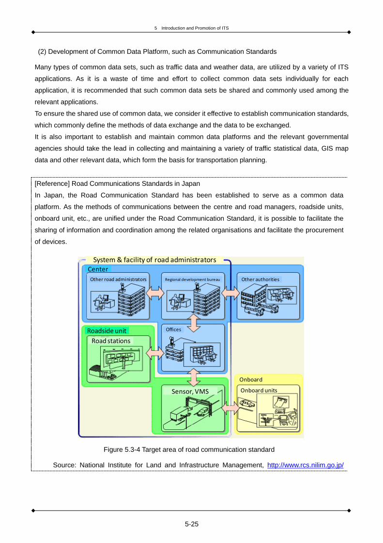
5 Introduction and Promotion of ITS
5-25
(2) Development of Common Data Platform, such as Communication Standards
Many types of common data sets, such as traffic data and weather data, are utilized by a variety of ITS
applications. As it is a waste of time and effort to collect common data sets individually for each
application, it is recommended that such common data sets be shared and commonly used among the
relevant applications.
To ensure the shared use of common data, we consider it effective to establish communication standards,
which commonly define the methods of data exchange and the data to be exchanged.
It is also important to establish and maintain common data platforms and the relevant governmental
agencies should take the lead in collecting and maintaining a variety of traffic statistical data, GIS map
data and other relevant data, which form the basis for transportation planning.
[Reference] Road Communications Standards in Japan
In Japan, the Road Communication Standard has been established to serve as a common data
platform. As the methods of communications between the centre and road managers, roadside units,
onboard unit, etc., are unified under the Road Communication Standard, it is possible to facilitate the
sharing of information and coordination among the related organisations and facilitate the procurement
of devices.
Figure 5.3-4 Target area of road communication standard
Source: National Institute for Land and Infrastructure Management, http://www.rcs.nilim.go.jp/
System & facility of road administratorsCenter
Other road administrators Regional development bureau Other authorities
Roadside unit
Road stations
Offices
Onboard
Onboard unitsSensor, VMS

5 Introduction and Promotion of ITS
5-26
5.4 Step-Up Approach to the Introduction of ITS
5.4.1 Concept of Step-Up Approach
When introducing ITS, it is effective to take a step-up approach; start introducing devices and applications
which are in greater need and whose initial costs are lower and then extend them in stages, by foreseeing
and envisioning the future of ITS in terms of scalability, interconnectivity and other relevant factors.
In countries where road construction and improvement projects are continuously in progress, such as less
developed countries, it is effective to study the implementation of ITS and its applications in conjunction
with such individual road construction and improvement projects. This could contribute to the earlier
achievement of the benefits from the projects, while foreseeing and envisioning the future nationwide
deployment of ITS and the future scalability of ITS applications.
In the early stages of the introduction of ITS, it is effective to take the following actions in parallel; identify
issues relating to road traffic characteristics of target areas for ITS introduction, find ITS promotion
organisation and standardise ITS systems.
5.4.2 Example of Model Deployment Plan
Some examples of the step-up approach are shown below.
By ensuring a common understanding of the overall ITS system architecture in the initial stages, it is
expected that ITS can be deployed more efficiently and effectively without wasting time and effort and
without redoing the same process.
■Example of Expansion of ITS Applications using Transportation-related IC Cards
In the initial stage, IC cards are introduced to support public transportation applications and EFC is
introduced to allow a “touch and go” passage at an EFC tollgate.
↓
Shift to free-flow tolling solution using DSRC, etc.
↓
Evolve to multi-application DSRC systems.
■Example of Expansion of ITS Applications: Collection and Provision of Traffic Information Using Probe
car data Systems
(Offline) probe car data systems are introduced to identify traffic congestion areas and study the
selection of target areas for the introduction of probe car data systems. A digital road map (DRM)
utilizing trajectory data is prepared.
↓
Online probe car data systems are introduced to collect real-time traffic information.
Traffic information is further refined by using probe car data systems in conjunction with roadside

5 Introduction and Promotion of ITS
5-27
units (cameras and traffic counters).
Applications are further upgraded (provision of disaster information, regional information, etc.)
[Reference] Conceptual Flow of Step-Up Approach-Based Review
Figure 5.4-1 Conceptual flow of ITS deployment
■ITSの導入のステップイメージ■ITSの導入のステップイメージ
②ITSの導入
国家レベルでの
道路整備計画の
策定
ヒト・組織の基盤ヒト・組織の基盤道路インフラ通信インフラ道路インフラ通信インフラ
①道路インフラの整備
③ITSの改良・リプレイス
導入が望ましいITSメニュー
導入が望ましいITSメニュー
日本等が支援可能な内容例日本等が支援可能な内容例
関連計画・基準類の策定関連計画・
基準類の策定
各地方・各主要都市
での道路整備計画
の策定
道路整備計画に付
随したITS導入計
画・ITSマスタープラ
ンの策定
主要都市間、主要都
市内道路整備
道路の基礎データ収集支援系ITSメニュー(プローブ、カメラ等)
道路整備推進機関キーパーソンの育成
ITSの必要性・有効性のPR(セミナー開催、
テクニカルツアー招待等)
ITSの必要性・有効性のPR(セミナー開催、
テクニカルツアー招待等)
既存インフラ(携帯
回線網等)の活用
・道路整備プロジェクト支援・通信インフラ整備支援・通信の標準化支援
・道路整備プロジェクト支援・通信インフラ整備支援・通信の標準化支援
ITS推進キーパーソンの育成
ITS推進研究機関の育成(政府機関、大学等)
道路整備に合わせ
た通信インフラ整備
(光ファイバ等)
ITSセミナー開催キーパーソン等のトレーニング支援
ITSセミナー開催キーパーソン等のトレーニング支援
道路整備効果の早期発現に寄与するITSメニュー(道路交通状況把握、信号制御、交通管制、道路情報提供等)
道路現状調査支援、調査結果からのハード/ソフト
(ITS含む)施策提案支援
道路現状調査支援、調査結果からのハード/ソフト
(ITS含む)施策提案支援既存インフラを活用し
早期に実現可能なITSメニュー提案支援、導入支援
既存インフラを活用し早期に実現可能なITSメニュー
提案支援、導入支援
道路整備計画策定調査支援
道路整備計画策定調査支援
道路現状調査支援、調査結果からのハード/ソフト
(ITS含む)施策提案支援
道路現状調査支援、調査結果からのハード/ソフト
(ITS含む)施策提案支援
競合国参入状況の分析競合国との比較資料作成
競合国参入状況の分析競合国との比較資料作成
国家レベルでのITS推進組織の形成
ITSマスタープラン等策定支援
ITSマスタープラン等策定支援
ITS標準化
ITS関連基準類策定
既存道路も含めたITSメニューの導入・有料道路ETC化・過積載車両管理・防災管理支援・道路管理支援・公共交通支援等
より高度なITSメニューの導入・環境改善支援・ロードプライシング・国境管理支援・バリアフリー支援・物流支援 ・・等
導入済ITSのリプレイス(ETC等)
・相手国側のITS標準化・基準類策定等の支援・標準化策定に向けたセミナー等の開催
・相手国側のITS標準化・基準類策定等の支援・標準化策定に向けたセミナー等の開催
ITSマスタープラン等の見直し(新たなメニュー追加、既設ITS施設等の機能拡張等)既設のITS施設等のリプレイス計画策定
・日本型ITSの拡張性PR導入に向けた実証実験・デモンストレーション実施・高度なITSメニュー導入に向けたセミナー等開催
・日本型ITSの拡張性PR導入に向けた実証実験・デモンストレーション実施・高度なITSメニュー導入に向けたセミナー等開催
日本型ITSの拡張性PR導入に向けた実証実験・
デモンストレーション等の実施
日本型ITSの拡張性PR導入に向けた実証実験・
デモンストレーション等の実施
ITS推進組織の運営・拡張
・推進組織づくりの支援・組織結成に向けた調整・
セミナー等の開催
・推進組織づくりの支援・組織結成に向けた調整・
セミナー等の開催
推進組織づくりの継続的な運営支援
推進組織づくりの継続的な運営支援
道路プロジェクトの
継続実施
・道路整備プロジェクト支援・道路整備にあわせた
ITS導入支援
・道路整備プロジェクト支援・道路整備にあわせた
ITS導入支援
Image of ITS deployment
1. R
oad
dev
elo
pm
ent
2. I
ntr
od
uct
ion
of
ITS
3. I
mp
rove
men
t,
rep
lace
men
t o
f IT
S
Development of related plan, STD
Road systemComm. system
Base of human, organization
Desirable ITS apps.
Support for road development plan
Support for ITS introduction using existing system
Support for investigation of current road
Seminar, technical tours
Support for master plan
Support for road development, comm. System, standardization
Support for ITS seminar, training of key person
Support for suggestion of policy
Comparison with opponent countries
Support and seminars for standardization of ITS
Support for road development project Support for
establishment of developing organization
FOT and demonstration for introduction
Continuous support for establishment of organization
FOT and demonstration for introduction
Making of road development plan in national level
Making of road development plan in each region
Utilization of existing system (cellular network, etc.)
Road developing organization, education of key persons
Basic data of roadData collection (probe, camera)
Making of ITS introduction plan, ITS master plan
Development of roads between and within primary cities
Communication system with road development
Education of ITS development key person
Establishment of ITS R&D institute
ITS apps. with immediate effects (road traffic monitoring, signal control, traffic control, information provision, etc.
Standardization of ITS
Continuous implementation of road project
Establishment of ITS developing organization in national level
Introduction of ITS apps. including existing roads- EFC- Overweight vehicle
management- Prevention for disaster- Road management- Support for public
transport
Operation and enlargement of ITS developing organization
Revision of ITS master plan, replacement of existing ITS facilities
Replacement of existing ITS
Introduction of more advanced ITS apps.- Support for
environmental improvement
- Road pricing- Border management- Support for logistics

5 Introduction and Promotion of ITS
5-28
5.5 Training and Education
5.5.1 Need and Necessity of Training and Education
In order to operate and deploy ITS on a sustainable basis, it is essential to continually train and educate
the expert engineers who are thoroughly versed in ITS.
Expertise and knowledge about ITS that needs to be acquired include the ability to identify issues in target
areas and routes and propose solutions using ITS; component technologies necessary for the
development of ITS systems (such as communication technologies); the ability to develop organisations
and systems to support the introduction of ITS; and the ability to operate and evaluate ITS systems.
5.5.2 Useful Tools for ITS Training and Education
It is helpful to effectively utilize websites and other available materials concerning ITS when implementing
ITS training and education. Some of the available guidebooks and websites that are useful for ITS training
and education are shown below. In order to ensure the successful introduction of ITS, it is also useful to
review the examples of ITS introduction in other countries where the effectiveness of ITS has already
been measured.
■ Examples of Useful Guidebooks and Websites for ITS Training and Education
○ ITS Technical Notes (World Bank)
http://go.worldbank.org/0TF9LEGIL0
○ Road Network Operations & Intelligent Transport Systems Manual(PIARC)
http://www.piarc.org/en/knowledge-base/road-network-operations/Road-Network-Operations-Intelligent
-Transport-Systems-Manual/
○ ITS-JAPAN
http://www.its-jp.org/
○Road Bureau, Ministry of Land, Infrastructure, Transport and Tourism, JAPAN
http://www.mlit.go.jp/road/road_e/index_e.html
○ITS Division, National Institute for Land and Infrastructure Management, MLIT, JAPAN
http://www.nilim.go.jp/lab/qcg/eindex.htm
○Japan International Cooperation Agency (JICA)
http://www.jica.go.jp/english/index.html
○Japan Society of Civil Engineers (JSCE)
http://www.jsce.or.jp/
○Asian Civil Engineering Coordinating Council( ACECC)
http://www.acecc-world.org/
○International Association of Traffic and Safety Sciences( IATSS)
http://www.iatss.or.jp/en/

5 Introduction and Promotion of ITS
5-29
Reference
[1] United Nations, Department of Economic and Social Affairs, Population Division (2014). World
Urbanization Prospects: The 2014 Revision, Highlights (ST/ESA/SER.A/352).
[2] OECD/ITF (2015), ITF Transport Outlook 2015, OECD Publishing/ITF.
http://dx.doi.org/10.1787/9789282107782-en
[3] IEA (2013), CO2 Emissions from Fuel Combustion 2013, IEA, Paris. DOI:
http://dx.doi.org/10.1787/co2_fuel-2013-en
[4] World Health Organization (2008). The global burden of disease: 2004 update.
[5] ITS Forum (2009). Experimental Guideline for Vehicle Communications System using 700
MHz-Band, http://www.itsforum.gr.jp/Public/Eguideline/index.html
[6] Japan Society of Traffic Engineers (2006). Manual on Traffic Signal Control, Revised Edition [in
Japanese]
[7] HIDO (2015). ITS Handbook.
[8] Ministry of Transportation and Communications of Taiwan (2004). The Master Plan of Intelligent
Transport Systems in Taiwan. Executive Summary of the 2004 Edition.

5 Introduction and Promotion of ITS
5-30

Appendix: Acronyms
6-1
6. Appendix: Acronyms

Appendix: Acronyms
6-2
A AHS Advanced Cruise-Assist Highway Systems
ANPR Automatic number plate recognition
ARIB Association of Radio Industries and Businesses
ASK Amplitude Shift Keying
ASL Application Sub-Layer
ATM Active Traffic Management
B BPSK Binary Phase Shift Keying
C CBD Central Business District
CCTV Closed-Circuit Television
C-ITS Cooperative ITS
D DQPSK Differential Quadrature Phase Shift Keying
DRB Digital Radio Broadcasting
DRG Dynamic Route Guidance
DRM Digital Road Map
DSRC Dedicated Short Range Communications
E EFC Electronic Fee Collection
EPS Electronic Parking System
ERP Electronic Road Pricing
ETC Electronic Toll Collection
EV Electric Vehicle
G GNP Gross National Product
GNSS Global Navigation Satellite System
GPS Global Positioning System
H HMI Human Machine Interface
I IC Interchange
IEA International Energy Agency
ISM Industry science medical
ITF International Transport Forum
ITS Intelligent Transport Systems
IVI In vehicle Information

Appendix: Acronyms
6-3
J JBIC Japan Bank for International Cooperation
JICA Japan International Cooperation Agency
L LOS Line of Sight
M MLIT Road Bureau of Ministry of Land, Infrastructure, Transport, and Tourism
MRF Markov Random Field
MODERATO Management by Origin-Destination Related Adaptation for Traffic Optimization
MOVA Microprocessor Optimized Vehicle Actuation
N NILIM National Institute for Land and Infrastructure Management
O OBU On Board Unit
ODA Official Development Assistance
OECD Organization for Economic Cooperation and Development
OPAC Optimized Policies for Adaptive Control
P PFI Private Finance Initiative
PPP Public Private Partnership
PRODYN Programming Dynamic
PTPS Public Transport Priority System
Q QPSK Quadrature Phase Shift Keying
QZSS Quasi-Zenith Satellite System
R RFID Radio Frequency Identification
RSU Road Side Unit
S SCATS Sydney Coordinated Adaptive Traffic Systems
SCOOT Split Cycle Offset Optimization Technique
U UTOPIA Urban Traffic Optimization by Integrated Automation
V VICS Vehicle Information and Communication System
VMS Variable Message Signboard
V2I Vehicle to Infrastructure
V2V Vehicle to Vehicle


Intelligent Transport Systems (ITS)
Introduction Guide
Version 1.1
August 2016
Japan Society of Civil Engineers
(JSCE)
The Asian Civil Engineering Coordinating Council
(ACECC)


Intelligent Transport Systems (ITS ) Introduction G
uide