intelligent gripper., with multi-sensor …€¦ · this thesis presents the intelligent gripper,...
TRANSCRIPT
INTELLIGENT GRIPPER., WITH MULTI-SENSOR FINGER PAD,
FOR THE SARCOS DEXTROUS ARM
bu
Ping Zhang
Department of Elecûical Engineering
Center for Intelligent Machines
McGill University
Montréal, Québec
Canada
A DK3SERTATlON
SUBMITTED TO THE FACULTY OF GRADUATE STUDIES AND RESEARCH
OF MCGILL UNIVERSITY
IN PARTIAL FULFILLMENT OF THE REQUIREMENTS FOR
THE DEGREE OF MASTER OF ENGMEERCNG
Copyright O 1999 by Ping Zhang

National Library 1*1 of Canada Bibliothéque nationale du Canada
Acquisitions and Acquisitions et Bibliographie Services services bibliographiques
395 Wellington Street 395. ruet Wellinglon OnawaON K 1 A W OtrawaON K l A W Canada canada
The author has granted a non- exclusive licence allowing the National Library of Canada to reproduce, loan, distribute or seil copies of this thesis in microfom, paper or electronic formats.
L'auteur a accordé une iicence non exclusive pexmettant à la Bibliothèque nationale du Canada de reproduire, prêter, distribuer ou vendre des copies de cette thèse sous la fome de microfiche/film, de reproduction sur papier ou sur format électronique.
The author retains ownership of the L'auteur conserve la propriété du copyright in this thesis. Neither the droit d'auteur qui protège cette thèse. thesis nor substantial extracts fiom it Ni la thèse ni des extraits substantiels may be printed or othenvise de celle-ci ne doivent être imprimés reproduced without the author' s ou autrement reproduits sans son permission. autorisation.

Abstract
This thesis presents the Intelligent Gripper, a low cost instrumented robot finger pad
which is equipped with an 8 x 8 tactile sensing array and a 2 x 2 proximity sensing grid.
The complete system is composed of three modules. The capacitive tactile sensing array
utilizes a dual strip construction to improve its robustness and simplicity, a technology
initially developed by Sarcos Research Inc- The proximity network is based on infiared
range sensing technology. The microprocessor based interface module gives the system
intelligent capability. In order to reduce the noise and to improve the system modularity,
al1 electric circuitry is localized. The modular architecture gives the system excellent
portability.
Following the comprehensive evaluation and characterization of the tactile sensing array
and its associated electronic system, an experimental exploration to use the tactile sensor
in transient contact force control is presented. It is found that using feedback fiom tactile
sensor stabilizes the force control. However, the highest performance for transient force
control is achieved from a combined feedback fiom tactile sensor and joint force sensor.
Résumé
Cette thèse présente une préhenseur intelligente, une garniture des doigts robotiques,
équipée d'une matrice (8 x 8) de capteurs tactile et une grille (2 x 2) des capteurs de
prosimité. C'est une design economique et très portable. La matrice tactile capacitif
est basée sur la technologie dévelopé initialement par Sarcos Research Inc., il est de
construction de bande duelle pour améliorer sa robustesse et simplicité. La réseau
de proximité emploie la technique mesurant dans la limite d'infrarouge. Un module
d'interface à base de microprocesseur donne au système la capacité intelligente. Pour
réduire le bruit et pour améliorer la modularité du système, tous les circuits électriques
sont localisés.
.Après l'évaluation et la caractérisation complètes de matrice tactile et de son système
électronique associé, une exploration expérimentale d'utiliser le capteur tactile dans la
commande de force de contact passagière est présentée. On constate que l'utilisation
du feedback tactile stabilise la commande de force. De plus, un combinaison de capteur
tatciIe et capteur joint force donne le meilleur performance pour la commande de force
d'impact.
Acknowledgements
1 would like first and foremost to express my gratitude to my supervisor, Professor
John M. Hollerbach, whose support and encouragement were indispensable throughout
my master's program. He contributed a great deal of his tirne, effort and thought to
the work presented in this dissertation. Professor Hollerbach showed dedication to
his students and his profession. During the years of my study in the program, 1 also
received generous financial support frorn hirn, without which it would be impossible
for me to complete this program. 1 consider myself fortunate to have been working in
association with him.
1 would also like to express my gratitude to Professor Martin Buehler and Doctor
Yangming Xu. Professor Buehler dedicated a large amount of time on many technical
details and gave numerous valuable comments. Without his contribution, this thesis
would not be completed. Doctor S u had been my mentor through out the years when
1 \vas morking in Biorobotics Lab. It \vas a great pleasure to work with him because
of his brilliant intelligence and great personality.
1 am grateful to the Center for Intelligent Machines and IRIS, and the Center for En-
gineering Design, University of Utah for their financial and material support. Thanks
to Sarcos Research Inc. for allowing me to use their initial technology and facilities
to develop the tactile sensor. Special thanks should go to David Johnston of Sarcos
for his comprehensive help and constructive suggestions. Without his efforts, most of
the experiments would not be possible or conclusive.
1 wish to thank al1 my colleagues and friends during my years with Biorobotics Lab
both at McGill University and a t University of Utah. Special mention should be made
of Ali Nahvi, Zhiling Qiu and Donghai Ma.
Finally, I give my thanks to my wife, Xiaoyan, for her constant support through the
years and for the cheer and love we share in the family.
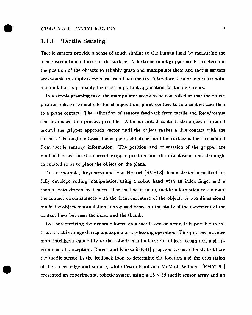
Figure 0.1: Interface module PCB
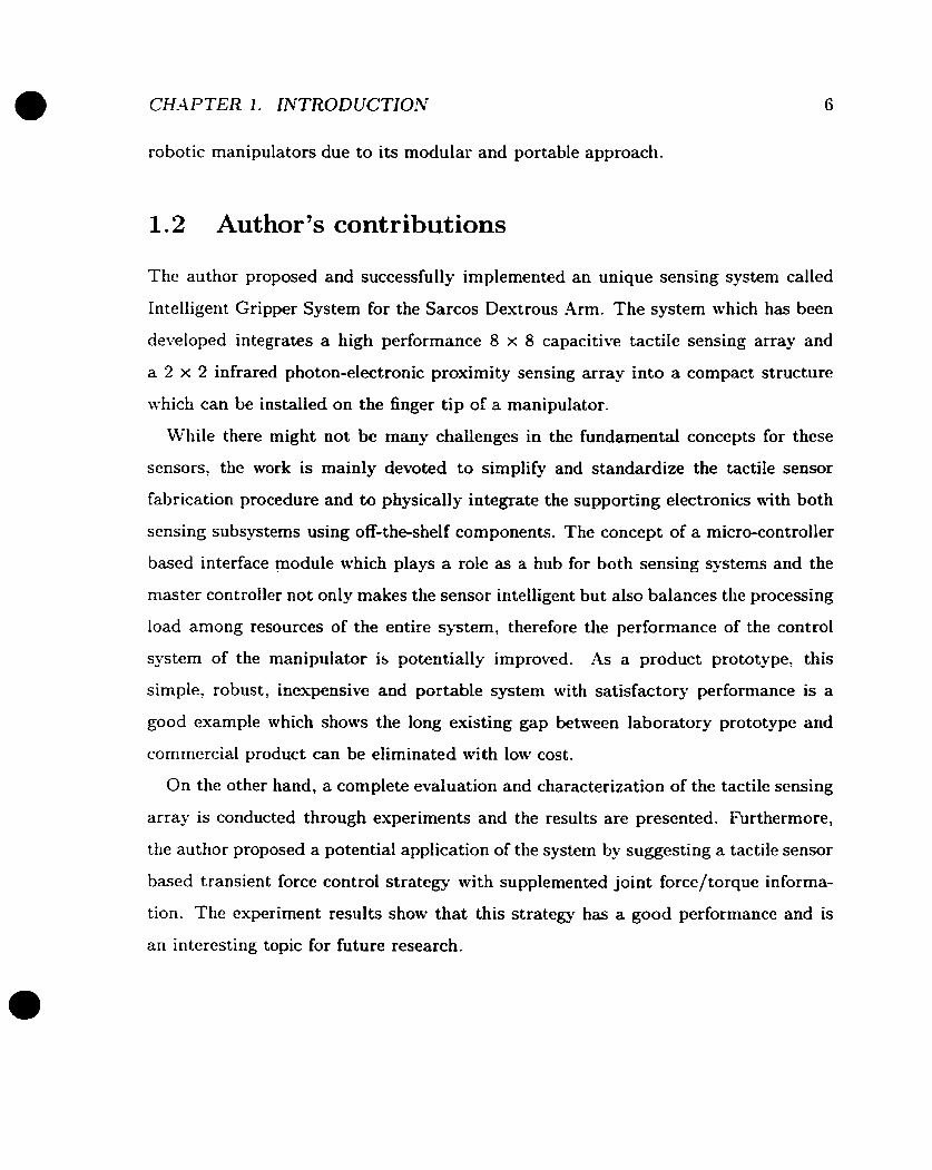
Figure 0.2: Proximity sensing subsystem PCB

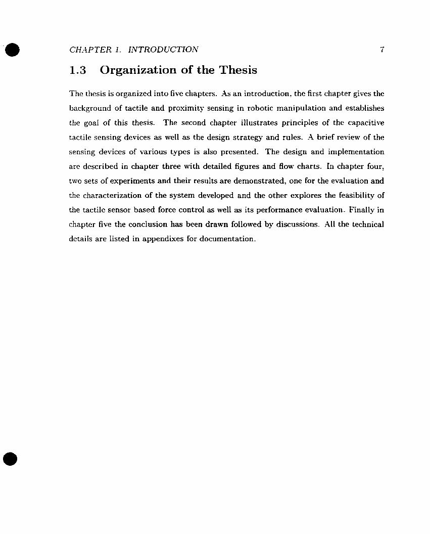
Figure 0.3: Tactile subsystem (top view): tactile array and back PCB
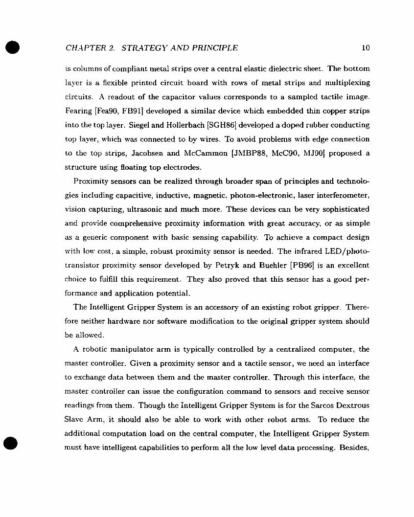
Figure 0.4: Tactile subsystem (bottom view): localized circuitry and back PCB
Contents
. . -4bstract . . . . . . . . . . . . . . . . . . . . . . . . . . . . . . . . . . . . . 11
... . . . . . . . . . . . . . . . . . . . . . . . . . . . . . . . . . . . . . Résumé iii
-kknowledgements . . . . . . . . . . . . . . . . . . . . . . . . . . . . . . . iv
1 Introduction 1
1.1 Motivation and Review . . . . . . . . . . . . . . . . . . . . . . . . . . 1
1.1.1 Tactile Sensing . . . . . . . . . . . . . . . . . . . . . . . . . . 2
1.1 -2 Proximity Sensing . . . . . . . . . . . . . . . . . . . . . . . . . 4
1.1.3 TheGoal . . . . . . . . . . . . . . . . . . . . . . . . . . . . . a 1.2 -4uthor's contributions . . . . . . . . . . . . . . . . . . . . . . . . . . 6
1.3 Organization of the Thesis . . . . . . . . . . . . . . . . . . . . . . . . 7
2 Strategy and Principle
. . . . . . . . . . . . . . . . . . . . . . . . . . . 2.1 System Specifications
2.1.1 Functionality . . . . . . . . . . . . . . . . . . . . . . . . . . . 8
. . . . . . . . . . . . . . . . . . . . . . 2.1.2 Technical Specification 11
. . . . . . . . . . . . . . . . . . . . . . . . . 2.2 Tactile Sensing Principle 13
3 Development 17
. . . . . . . . . . . . . . . . . . . . . . . . . . 3.1 Design at System Level 17
. . . . . . . . . . . . . 3.1.1 Physical Restrictions and Design Rules 17
. . . . . . . . . . . . . . . . . . . . . . . 3.1.2 System Architecture 21
. . . . . . . . . . . . . . . . . . . . . . . . 3.1 Tactile Sensing Subsystem 24
vii
. . . . . . . . . . . . . . . . . . . . . . . 3.2.1 Tactile Sensing Array 24
. . . . . . . . . . . . . . . . . . . . 3.2 -2 Tactile Sensing Electronics 27
. . . . . . . . . . . . . . . . . . . . . . 3.3 Proximity Sensing Subsystem 31
. . . . . . . . . . . . . . . . . . . . . . . . . . . . . 3.4 Interface Module 36
. . . . . . . . . . . . . . . . . . . . . . . . . . . . 3.4.1 Architecture 36
. . . . . . . . . . . . 3.4.2 Boot Strap and EEPROM Programming 43
. . . . . . . . . . . . . . . . . . . . . . . . . . . . . . . 3.4.3 Drivers 44
4 Experimentation 51
. . . . . . . . . . . . . . . . . . . . . 4.1 Tactile Sensor Characterization 51
. . . . . . . . . . . . . . . . . . . . . . . . . 4.1.1 Experiment Setup 52
. . . . . . . . . . . . . . . . . . . . . . . . . . 4.1.2 Static Property 53
. . . . . . . . . . . . . . . . . . . . . . . . 4.1.3 Dynamic Property 54
. . . . . . . . . . . . . . . . . . . . . . . . . . 4.1.4 Spatial Property 54
. . . . . . . . . . . . . . . . . . . . . . . 4.1.5 Electrical Properties 56
4.2 Using Tactile Sensor in the Contact Force Control . . . . . . . . . . . 59
5 Discussion and Conclusion 66
. . . . . . . . . . . . . . . . . . . . 5.1 The Conductive Silicone Shielding 66
. . . . . . . . . . . . . . . . . . . . . . . . . . . . . . . . 5.2 Future Work 70
5.2.1 Application of the Intelligent Gripper System . . . . . . . . . . 70
. . . . . . . . . . . . . . . . . . . . . . . 5.2.2 Sensor Improvernents 71
. . . . . . . . . . . . . . . . . . . . . . . . . . . . . . . . . 5.3 Conclusion 73
A Materials used for Tactile Array 76
B Schernatics
C Lists of the MC68HCll Program
Bibliography
... V l l l

List of Tables
. . . . . . . . . . . . . . 2.1 Mechanical specifications of the finger joints 12
3.1 -4vailable gains of the programmable amplifier . . . . . . . . . . . . . 34
3.2 List of signals of host interface Pm . . . . . . . . . . . . . . . . . . . . 39
. . . . . . . . . . . . . . . . . . . . . . . . 3.3 Address of external devices 42
4.1 List of tactile arrays using different shielding materials . . . . . . . . 58
List of Figures
0.1 Interface module PCB . . . . . . . . . . . . . . . . . . . . . . . . . .
0.2 Proximity sensing subsystem PCB . . . . . . . . . . . . . . . . . . . .
0.3 Tactile subsystem (top view): tactile array and back PCB . . . . . . .
0.4 Tactile subsystem (bottom view): localized circuitry and back PCB .
2.1 A single tactile ce11 . . . . . . . . . . . . . . . . . . . . . . . . . . . .
2.2 Basic tactile sensing unit . . . . . . . . . . . . . . . . . . . . . . . . . 2.3 Corn plex multiplexing for a tactile array . . . . . . . . . . . . . . . .
2.4 Built-in multiplexing for a tactile array . . . . . . . . . . . . . . . . .
3.1 System level block diagram of the intelligent Gripper System . . . . .
3.2 Modular architecture for the Intelligent Gripper System . . . . . . . .
3.3 Layout of the gripper finger . . . . . . . . . . . . . . . . . . . . . . .
3.4 Modified tactile array with built-in multiplexing . . . . . . . . . . . .
3.5 Dual strip with Aoating plate tactile array . . . . . . . . . . . . . . .
3.6 Assembly of gripper finger with tactile and proximity sensors . . . . .
3.7 Physical dimension of a tactile ce11 . . . . . . . . . . . . . . . . . . . .
3.8 Block diagram of tactile array supporting circuitry . . . . . . . . . . .
3.9 Offset and gain scheduling for tactile sensing . . . . . . . . . . . . . .
3.10 Block diagram for proximity sensing array (four channels) . . . . . .
3.11 Typical response of a infrared LED/photon transistor proximity sensor
3.12 Programmable amplifier for proximity sensing to eliminate saturation
and to increase the sample resolution . . . . . . . . . . . . . . . . . .

. . . . . . . . . . . . . . . 3.13 Flow chart for gain scheduling mechanism 35
. . . . . . . . . . . . . . . . . . . . 3.14 Block diagram of interface module 37
. . . . . . . . . . . . . . . . . 3.15 Tactile cell address mapping (top view) 38
. . . . . . . . . . . . . . . . . . 3.16 Read/Write cycles of the parallel port 40
. . . . . . . . . . . . . . . . . . . 3.17 Interface between AD538 and MCU 41
. . . . . . . . . . . . . . . . . . 3.18 Interface between AD7871 and MCU 42
. . . . . . . . . . . . . . . . . . . 3.19 System hardware resource mapping 43
. . . . . . . 3.20 MCU mode selection with the corresponding reset vector 44
. . . . . . . . . . . . . . . . . . . . . . . . . 3.2 1 Block diagram of Loader 45
. . . . . . . . . . . . . . . . . . . . 3.22 Block diagram at task (top) level 47
. . . . . . . . . . . . . . . . . . . . 3.23 Block diagram of application task 48
. . . . . . . . . . . . . . . . . . . . . . . 3.24 Block diagram of demo task 49
. . . . . . . . . . . . . . . . . . . . . . 3.25 Block diagram of testing task 50
. . . . . . . . . . . . . . . . . . . . . . . . . . . . 4.1 Experimental setup 52
. . . . . . . . . 4.2 Hysteresis loop in the static response of a tactile sensor 53
. . . . . . . . . . . . . . . . . . . 4.3 Single tactel response to lateral scan 55
. . . . . 4.4 Accuracy of point source localization using weighted averages 56
. . . . . . . . . 4.5 Noise level vs . pre-sampling delay for the tactile array 57
4.6 Tactile image of a degraded array contacting with an aluminum bar . 59
4.7 Tactile image of a normal array contacting with the same aluminum bar 60
4.8 Block diagram of a loadcell or tactile sensor based transient force con-
. . . . . . . . . . . . . . . . . . . . . . . . . . . . . . . . . . . troller 61
. . . . . . . . . . . . . . 4.9 Transient force control with loadcell feedback 62
. . . . . . . . . . 4.10 Transient force control with tactile sensor feedback 62
4.11 Block diagram of a transient force controller with composite tactile
. . . . . . . . . . . . . . . . . . . . . . . . . sensor/loadcell feedback 64
. . . . . . . . 4.12 Transient force control with composite sensor feedback 65
5.1 Tactile sensor with conductive shielding and its electrical model . . . 67
. . . . . . . . . . . . . . . . . . . . . . . 5-2 Modified tactile sensing unit 68
5.3 Illustration of a tactile array with degraded shielding and its elcctrical
mode1 . . . . . . . . . . . . . . . . . . . . . . . . . . . . . . . . . . . 69
. . . . . . . . . . B.1 Interface module: i'vICU, address decoding and SC1 78
. . . . . . . . . B.2 Interface module: Pt: P, and tactile signal processing 79
. . . . . . . . . . . . B.3 Interface module: Excitation generation and Pm 80
B.4 Proximity subsystem: Ali analog processing and excitation driving .
. . . . . . . . . . (One channel is shown . The rest three are identical) 81
B -5 Proximi ty subsystem: Excitation generation and multiplexing, gain
. . . . . . . . . . . . . . . . . . . . . . . . . . . . . scheduling control 82
s i i

Chapter 1
Introduction
1.1 Motivation and Review
In recent years we have been witnessing implementation cf automated handling ma-
chines in various scientific research and industry rnanufacturing environments. While
automation and robotics are becoming a matter of routine in our modern industrial-
ized society we need a wide spread of robots and associated hardware and software.
To rneet with these requirements, precise data must be provided as fuel for the in-
formation processing. These goals will partly be achieved if cheap, reliable and easily
im plernentable sensor systems are introduced.
Adding sensing capability to a robot end-effector provides the robot with intelligent
perception capability and flexibility of decision making. To perform intelligent tasks,
robots are highly required to perceive their operating environment, and react accord-
ingly With this regard, tactile sensors and prosimity sensors offer to extend the scope
of intelligence of a robot for performing tasks which require object recognition, touch-
ing and manipulation. The goal is to develop an intelligent robotic manipulator which
is able to "see and feel" and make the decisions based on the knowledge acquired from
its sensing systern.
CHA PTER 1. INTRODUCTION
1.1.1 Tactile Sensing
Tactile sensors provide a sense of touch similar to the human hand by measuring the
local distribution of forces on the surface. -4 dextrous robot gripper needs to determine
the position of the objects to reliably grasp and manipulate them and tactile sensors
are capable to supply these most useful parameters. Therefore the autonomous robotic
manipulation is probably the most important application for tactile sensors.
In a simple grasping task, the manipulator needs to be controlled so that the object
position relative to end-effector changes from point contact to line contact and then
to a plane contact. The utilization of sensory feedback from tactile and force/torque
sensors makes this process possible. After an initial contact, the object is rotated
around the gripper approach vector until the object makes a line contact with the
surface. The angle between the gripper held object and the surface is then calculated
from tactile sensory information. The position and orientation of the gripper are
modified based on the current gripper position anc; the orientation, and the angle
calculated so as to place the object on the plane.
.4s a n esample, Reynaerts and Van Brussel [RVB93] demonstrated a method for
full- envelope rolling manipulation using a robot hand with an index finger and a
thumb, both driven by tendon. The method is using tactile information to estimate
the contact circumstances with the local curvature of the object. -4 two dimensional
mode1 for objert manipulation is proposed based on the study of the movement of the
contact Iines between the index and the thurnb-
By characterizing the dynamic forces on a tactile sensor array, it is possible to ex-
tract a tactile image during a grasping or a releasing operation. This process provides
more intelligent capability to the robotic manipulator for object recognition and en-
vironmental perception. Berger and Kholsa [BK911 proposed a controller that utilizes
the tactile sensor in the feedback loop to determine the location and the orientation
of the object edge and surface, while Petriu Emil and McMath William [PMYT92]
presented an experimental robotic system using a 16 x 16 tactile sensor array and an

instrumented compliant wrist developed specifically for the active perception of geo-
metric profiles of the object surface. Rafla and Merat [Rh4901 developed a more soph-
isticated system with multiple sensing devices; a Vision-Traction Exploration (VTE)
strategy for generating surface descriptions from range vision and tactile sensor data.
The range vision system provides prirnary sparse 3-D data about the surface. With
the use of tactile and force torque sensors under position control, supplementary data
are obtained and processed. These two sets of data are integrated and processed in a
higher level for precise surface representation and classification.
On the other hand, the control of the behavior of manipulators during gripper-object
contact transient remains a big challenge due to the high non-linearity of the process.
By integrating joint torque sensing and tactile sensor spatial and force information,
it is possible to increase the sensitivity in measuring the applied force and contact
locations, therefore improves the performance of the control. Using tactile sensors on
a whole arrn rnanipulator overcomes a number of limitations in the joint torque method
due to insufficient or low accuracy measurements [GT89].
Tactile sensing is not only a powerful tool for intelligent robotic research and devel-
opment, but also has great potentials in industry automation. -4 tactile sensor systern,
capable of providing pressure images of the objects which are held in a robot gripper,
will be a very useful aid for programmable assembly tasks and will provide information
which enables verification and correction of an assembly process.
While industrial robots have grown to be a major force in production lines, the
positioning control type robot is difficult to be employed in the automation of assembly
lines where the robot must deliver a delicately controlled force and at the same time
adapts itself to the constraining conditions of workplaces. A robot needs the accurate
description of the location of the parts to control the end cffector. However, it is
1 e sensor extremely difficult to improve absolute positioning accuracy [AsaSG]. The ta-t'l
and the cornpliance device can compensate for or absorb the relative errors between
end-effector and work pieces.

1.1.2 Proxirnity Sensing
Cost-effective solutions to autonomous robot control and to the industry production
problems through flexible automation require the ability to adapt to circumstances
and tasks which could change with great frequency. An autonomous robot deals
with the empirical world which is never fully predictable. While tactile sensing offers
a solution to this issue, a prosimity sensor is a non-touch alternative to physically
actuated devices. In some cases where physical contact is hazardous a proximity
sensor may be the only solution.
Proximity sensors are able to extract geometrical information about the surrounding
environment and to perceive other relevant features of the selected objects. With
proximity sensors, the robotic manipulator is able to construct a geometric mode1 of
the unknown environment without making phÿsical contact with the environment.
Proximity sensors have two major applications - collision detection and object re-
cognition. Real-tinie collision detection has an important role as part of a safety system
in telerobotics and autonomous robotics application. The accurate sensing of its pros-
imity sensor enhances the ability of an autonomous robotic manipulator to operate
in confined spaces while avoiding unwanted collisions. CVegerif and Rosinski [Lee921
developed a sensor based obstacle avoidance strategy for a SCARA-type robot ma-
nipulator using infrared proximity sensors to provide real time knowledge of the en-
vironment surrounding the manipulator. The control algorithm produces a collision
free patli around detected obstacles based on proximity information, while allowing
the end-effector to reach the desired goal position, and Novak and Feddema [NF921
addressed the issue of collision avoidance in unknown or partially modeled environ-
ments using a capacitive proximity sensor which can detect the obstacles u p to 40
cm.
Similar to the tactile sensing, proximity sensors also can be used to identify the
geometrical characters such as edge and surface profiles of the manipulated object
in a non-contact fashion. Proximity sensors can become fingers, hands and even the

tactile cont rol of critical and routine manufacturing and inspection process - from the
p o w r systeni maintenance, the pharmaceutical inspection and the food packaging to
the manufacture of ships, automobiles, and airplanes in which case it is important to
have the robot arm in precision tracking of the surface and the contour of an object.
Lee (Lee921 proposed an optical proximity system, capable of measuring the distance
to the orientation and the discontinuity at a local area of an object surface. Lee
and Hahn [LHSl] also used an optical proximity sensor system mounted on a robot
end-effector for 3-D quadric objects identification.
1.1.3 The Goal
There are numerous tactile and proxirnity sensing devices of various t-ype had been
developed since these sensing concepts were discovered. However, almost al1 of the
systems remain in the stage of laboratory prototype which are fragile, in-robust, and
difficult to fabricate. Also, due to the large quantity of sensor units involved, they
requirc significant processing potver which can be very expensive. For example, a
VME based real-time system with single CPU and general purpose anaiog 1/0 chan-
neIs costs thousands of dollars. Though some systems with good performance have
been developed, they are usuallÿ very expensive and only serve very specific scientific
research purposes.
The rapid decline in the cost of information processing power brought about by
the widespread availability of microprocessors and fast Pace in discovery of innovative
matcrials have driven fonvard the development of advanced sensing devices. I t is
possible now to bring a truly usable, robust and cheap system into reality. In this
thesis, we propose and implement a compact sensing system, the Intelligent Gripper
Systcm, which integrates sensing arrays for both tactile and proximity with smart and
user friendly functionality. The simplicity in the sensor fabrication process and the
state-of-art clectrical design assure it to be a product prototype. Though the system is
primarily designed for Sarcos Dextrous Slave Arm, it can be easily adapted for other
robotic manipulators due to its modular and portable approach.
1.2 Author's contributions
The author proposed and successfully implemented an unique sensing system called
Intelligent Gripper System for the Sarcos Destrous k m . The system which has been
developed integrates a high performance 8 x 8 capacitive tactile sensing array and
a 2 x 2 infrared photon-electronic proximity sensing array into a compact structure
which can be installed on the finger tip of a manipulator.
While there might not be many challenges in the fundamental concepts for these
sensors, the work is mainly devoted to simplify and standardize the tactile sensor
fabrication procedure and to physically integrate the supporting electronics with both
sensing subsysterns using off-the-shelf components. The concept of a micro-controller
bascd interface moduIe which plays a role as a hub for both sensing systems and the
master controiler not only makes the sensor intelligent but also balances the processing
load among resources of the entire system, therefore the performance of the control
system of the manipulator is potentially improved. As a product prototype, this
simple, robust, inexpensive and portable system with satisfactory performance is a
good example which shows the long existing gap between laboratory prototype and
commercial product can be eliminated with low cost.
On the other hand, a complete evaluation and characterization of the tactile sensing
array is conducted through experiments and the results are presented. Furthermore,
thc author proposed a potential application of the system by suggesting a tactile sensor
based transient force control strategy with supplemented joint force/torque informa-
tion. The experiment results show that this strategy has a good performance and is
an intercsting topic for future research.
CHAPTER 1. INTRODUCTION
1.3 Organization of the Thesis
The thcsis is organized into five chapters. .AS an introduction, the first chapter gives the
background of tactile and proximity sensing in robotic manipulation and establishes
the goal of this thesis. The second chapter illustrates principles of the capacitive
tactile sensing dcvices as well as the design strategy and rules. -4 brief review of the
sensing devices of various types is also presented. The design and implementation
are described in chapter three tvith detailed figures and flow charts. In chapter four,
two sets of experiments and their results are dernonstrated, one for the evaluation and
the characterization of the system developed and the other explores the feasibility of
the tactile sensor based force control as well as its performance evaluation. Finally in
chapter five the conclusion has been drawn followed by discussions. Al1 the technical
details are listed in appendives for documentation.

Chapter 2
Strategy and Principle
2.1 System Specifications
The purpose of this thesis is to design and to implement a product prototype of the nest
gcneration gripper system for Sarcos Destrous Slave Arm. In general, the entire design
specification falls into two categories, the functionality and technical specifications.
The Intelligent Gripper System integrates both tactile and proximity sensing devices
and is designed to work with the Sarcos Dextrous Slave -4rrn.
During the past years, numerous tactile sensing devices adopting a broad range
of principles and technologies have been developed [Dar89, HC921. In summary, al-
most al1 of the tactile sensors are based on conductive, inductive, capacitive, photo-
electric, magnetic, piezoelectric, electric-acoustic and silicone micromechanical prin-
ciples. Uldry and Ruse11 [UR921 made a tactile sensor using compliant elastomer, a
conductive rubber which changes conductivity under stress. Reston and Kolesar [RK89]
developed a sensor from piezoelectric polyvinylidene fluoride while Bergamasco [FDB88]
used piezoelectric polymer [PVFZ] for the similar device. -4 photo-elcctric approach
was rcported by Schoenwald and Martin [SM] with good results. A magnetic type

CH.4 PTER 2. STRATEG k' AND PRINCIPLE 9
tactile sensor array was developed by Vranish [Vra] but its spacing is 5mm wtiich is
relatively large. An ultrasonic emission tactile sensor was developed by Shinoda and
.Ando [SAg-L].
Tactile sensors using conductive elastomers are inexpensive and flexible. However,
these materials suffer from problems including hysteresis, contact noise, fatigue, low
sensitivity and nonlinear response [Hi182, Spe90j. Photo-electric tactile sensors tactile
sensors using optical fibers yield considerable sensitivity and can be made very small.
But they are very difficult to be packed into a modular device due to the presence of
photonic components and circuit ry. Piezo-electric tactile sensors and electro-acoustic
tactile sensors based on similar materials have been used most often because of their
Rexibility, fast response, good sensitivity and ability to provide multi-dimensional
sensing capability. However, they are either unable to measure static loads or too
complicated to multiplex. Magnetic and inductive tactile sensing devices are able to
sense shears as well as normal forces, but highly depend on the material properties
of the operating environment to achieve satisfactory performance. Besides. they are
not suitable to be implemented as arrays. Silicone micromechanical tactile sensors are
tiny structures "machined" from wafers of silicone using integrated circuit fabrication
techniques. Though they generally have very good sensing performance, these sensors
are not suitable for human-sized manipulators. They are also very expensive in small
quantity.
Capacitive tactile sensors have been popular with a number of research groups. They
offers satisfactory performance and can be fabricated into cuwed fingertips which is
essential for dexterous manipulation [FeaSO]. Construction techniques are relatively
simple and inexpensive, as are capacitive measurement and multiplexing electronics.
I t is the best solution to use capacitive tactile sensors for hurnan-sized manipulators
like the Sarcos Dextrous Arm.
There has been a number of publications on capacitive tactile sensing technology
since early 80's. Boie [Bois41 developed a three-layer sandwich structure. The top layer
CH-4 PTER 3. STRATEGY AND PRINCIPLE 10
is columns of compliant metal strips over a central elastic dielectric sheet. The bottom
layer is a flexible printed circuit board with r o m of metal strips and multiplesing
circuits. A readout of the capacitor values corresponds to a sampled tactile image.
Fearing [FeaSO, FB91] developed a similar device which embedded thin copper strips
into the top layer. Siegel and Hollerbach [SGH86] developed a doped rubber conducting
top layer, which was connected to ty wires. To avoid problems with edge connection
to the top strips, Jacobsen and McCammon (JMBP88: McC90, LLJ9OJ proposed a
structure using floating top electrodes.
Proximity sensors can be realized through broader span of principles and technolo-
gies including capacitive, inductive, magnetic, photon-electronic, laser interferorneter,
vision capturing, ultrasonic and much more. These devices can be very sophisticated
and provide comprehensive proximity information with great accuracy, or as simple
as a generic component with basic sensing capability. To achieve a compact design
with IOW cost, a simple, robust proximity sensor is needed. The infrared LED/photo-
transistor proximity sensor developed by Petryk and Buehler [PB961 is an excellent
choice to fulfill this requirement. They also proved that this sensor has a good per-
formance and application potential.
The Intelligent Gripper System is an accessory of an existing robot gripper. There-
fore neither hardware nor software modification to the original gripper system should
be allowed.
-4 robotic manipulator arm is typically controlled by a centralized computer, the
master controller. Given a proximity sensor and a tactile sensor, we need an interface
ta exchange data bctween them and the master controller. Through this interface, the
master controller can issue the configuration command to sensors and receive sensor
readings from them. Though the Intelligent Gripper System is for the Sarcos Dextrous
Slave Arm, it should also be able to work with other robot arms. To reduce the
additional computation load on the central computer, the Intelligent Gripper System
must have intelligent capabiIities to perform al1 the low level da ta processing. Besides,
Ive require no hardware modifications when it is connccted into or disconnccted from
the existing control system. Ideally, it should be a "plug and play" device. Therefore
a simple, clean, and standard interface is mandatory. On the other hand, maintenance
of a robotic system is a big headache especially to the scientific research communit_v,
the Intelligent Gripper System must be easy to use: easy to service: and it should have
built-in tools for debugging and calibration.
In summary, the Intelligent Gripper System is a portable sensing system including
a prosimity sensing subsystem and a tactile array. The system is able to perforrn al1
the prelimina- data processing and has a simple, clean and standard interface to the
central cornputer. It also has built-in debugging tools.
2.1.2 Technical Specification
Sarcos Dextrous Slave
-4s an accessory, many of the specifications of the Intelligent Gripper System are
identified according to its host, the Sarcos Dextrous Slave -4rm.
The Sarcos Dextrous Slave ,4rm is a human-size robot arm with ten Degrees Of
Freedom (DOF), made by Sarcos Research Inc. (390 Wakara Way, Salt Lake City,
UT84108). It has three DOF for the shoulder, one DOF for the elbow and three DOF
for the wrist. The Slave has one thumb with two DOF, one index finger with one
DOF and an additional passive index finger. Al1 joints are hydraulically driven. The
joint torque sensor is standard equipment for al1 joints. Al1 joints are equipped with
joint encoders or RVDTk Table 2.1 is the mechanical specifications of the three finger
joints.
Specifications
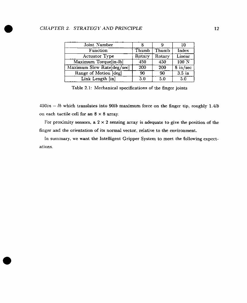
For tactile arrays, it is a compromise between sensor density and implementability.
As a low cost product prototype, it is realistic to have an 8 x 8 tactile array with O.lin
spacing. According to Table 2.1, the maximum torque of the rotational finger joint is
Joint Nuniber Function
Maximum Torque[in-lb] blaximum Slew Rate/deg/sec]
Table 2.1: Mechanical specifications of the finger joints
8 Thumb
. -,
Range of Motion [deg] Link L e n ~ t h lin1
450in - fb which translates into 9016 maximum force on the finger tip, roughly 1.416
on each tactile ce11 for an 8 x 8 array.
For proximity sensors, a 2 x 2 sensing array is adequate to give the position of the
finger and the orientation of its normal vector, relative to the environment.
In summary, we want the Intelligent Gripper System to meet the following expect-
ations.
-4ctuator Type 1 Rotary 450 200
9 Thumb
90 5-0
10 Indes
Rotary 450 200
Linear 100 N
8in/sec 90 5.0
3.5 in 5 .O
Tactile Sensing Subsystem:
Sensing Type: Capacitive
Array Type: Flat
Densi ty: 8 x 8 with O.lin spacing
Sensing Range: 0 - 1.41b
Prosimity Sensing Subsystem:
Sensing Type:
-4rray Type:
Density:
Sensing Range:
Infrared LED/Photo-transistor pair
Flat
2 x 2
O - 5 ~ m
Supporting Electronics:
Power Supply: 5.0C7, 5 1.OA
Sensor Resolution: 8 - 126it
weight : 5 1.016 (suitable to be installed on the robot arm)
Interface: One 8 bit parallel port, one RS-232 serial Port.
2.2 Tactile Sensing Principle
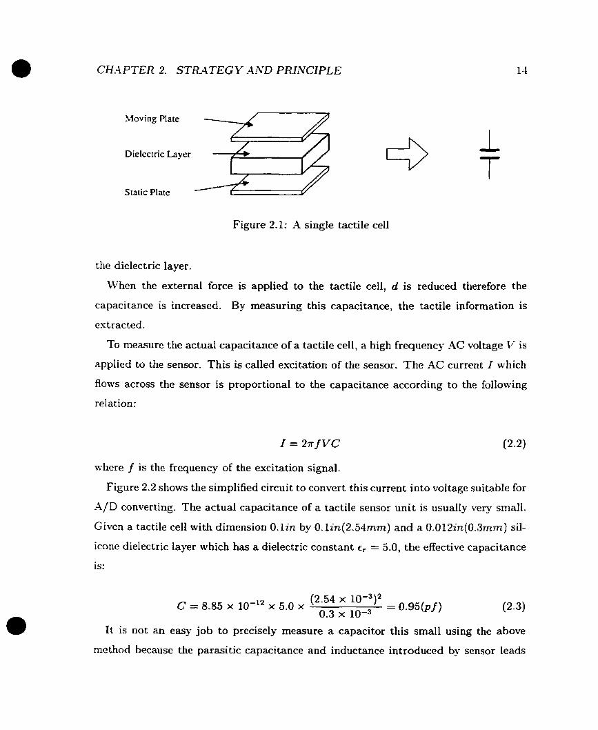
The Intelligent Gripper System uses capacitance based tactile sensing. Figure 2.1
shows the basic structure of a single tactiie sensor unit, a tactile cell. It has three
basic layers. The top is a moving plate and the bottom is a static plate, both are made
from conductive material. Between them is a dielectric layer, usually silicone or air.
If A is the area of the plates and assuming the distance d betwcen top and bottom
plates is much smaller than their dimensions, the capacitance of the ce11 is:
€of, A C=- d (2.1)
where €0 = 8.85 x 10-l2 Fm-' is the permittivity and c, is the dielectric constant of
Moving Plate
Dielcctric Layer
Static Plate
Figure 2.1: A single tactile ce11
the dielectric layer.
When the external force is applied to the tactile cell, d is reduced therefore the
capacitance is increased. By measuring this capacitance, the tactile information is
estracted.
To measure the actual capacitance of a tactile ceIl: a high frequency -4C voltage Ii is
applied to the sensor. This is called excitation of the sensor. The -4C current 1 which
Roms across the sensor is proportional to the capacitance according to the foliowing
relation:
where f is the frequency of the excitation signal.
Figure 2.2 shows the simplified circuit to convert this current into voltage suitable for
A/D converting. The actual capacitance of a tactile sensor unit is usually very small.
Given a tactile ce11 with dimension O. lin by O.lin(2.54mrn) and a 0.012in(0.3mm) sil-
icone dielectric layer which has a dielectric constant cr = 5.0, the effective capacitance
is:
I t is not an easy job to precisely measure a capacitor this small using the above
method because the parasitic capacitance and inductance introduced by sensor leads

Tactile Sensor R
1 - - -
Figure 2.2: Basic tactile sensing unit
I Multiplexor t-
Figure 2.3: Complex multiplexing for a tactile array
and the measuring circuitry can contribute significant errors. Besides, the circuit
shown above is a high gain, high impedance amplifier, a very small noise current
coupled by the wire at the input will easily cause significant damage to the signal
quality and integrity a t the output. It is a big challenge for the implementation.
There will be more discussion about this issue in the next chapter.
In order to stack a number of tactile sensors into an array, the multiplexing is
needed. One method (Figure 2.3) is to construct each tactile ce11 individually and use
independent multiplexing electronics for excitation and sampling.

CHAPTER 2. STRATEG k' AND PRINCIPLE
Figure 2.4: Buiit-in multiple'ung for a tactile array
-A better solution is to embed multiplexors into the architecture of the sensor array.
Figure 2.4 illustrates this design concept. There are two sets of conductive strips,
one functions as the static plates S and another functions as the moving plates M. -4
tactile ce11 is created at the intersection of each of S(s) and M(m) and is identified
by (s, m) where s and rn are indexes of the two conductit-e strip sets. The excitation
and the sampling are conducted through S(s) and R.l(m). Compared to Figure 2.3,
this method reduces the number of connections when there is a large number of tactile
cells involved, thereby improves the reliability.

Chapter 3
Development
3.1 Design at System Level
The systern architecture of the Intelligent Gripper System is directly based on its
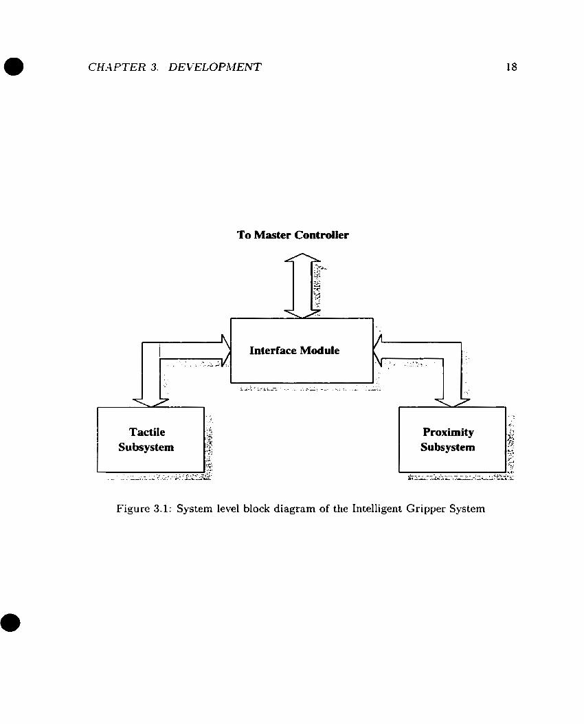
functionality defineci in Section 2.1. As sbown in Figure 3.1? there are three logical
modules. They are the tactile subsystem, the proximity subsystem and the interface
module. During the irnplementation, these three modules are not necessarily and
esclusively at three physical localities.
To develop a good system level design strategy so as to achieve the best performance
possible, we muse first understand the physical restrictions and establish the design
rules to deal with the real engineering problems caused by these restrictions.
3.1.1 Physical Restrictions and Design Rules
Tlic most significant physical restriction for the implementation is the lack of space.
The Intelligent Gripper System is an electronic product prototype which is ready for
production in small quantities. I t is not a customized product where the high material
and manufacturing cost can be tolerated. It also can not reach the quantity where the
application specific technology such as Application Specific Integrated Circuits (ASIC)
can be utilized. The only choice is to use off-the-shelf components and the mainstream
To Master Controller
r i Interface Module
Figure 3.1: System level block diagram of the Intelligent Gripper System
manufacturing process.
Like an- other human-sized robot arm, Sarcos Destrous Slave -4rm has a compact
sized gripper. Iiihile the tactile sensor array and proximity sensor heads including
LEDs and photo-transistors have to be located at the fingertip, there is barely enough
room in or on the finger to house al1 the associated electronic components and protect
them against wild movement of the gripper finger. The interface module, as defined
in the last chapter, has the intelligent capability to exchange sensor readings and con-
figuration information with master controller. Therefore it has to be a microprocessor
or microcontrollor based device, if not implemented with complex logical circuits. In
either case, it is more difficult to put the module a t the same place where both sensors
are located.
The solution is to pull some of the electronics away from the gripper finger and
put them close to the wrist, or remove the electronics off the robot arm if necessary.
This will certainly result in a modular design. It should be emphasized that, here
a "module" is physical module, which does not have to match the logical modules
esclusively(Figure 3.1). There could be less or more than three physical modules for
the system.
Whilc this sounds a good solution, it introduces problems and some could be serious.
First, the number of electrical connections among sensors, their associated electron-
ics, the interface module and the master controller must be reduced to minimum in
order to achieve good reliability. Meanwhile, al1 the wires have to be kept as short as
possible. This requires careful planning.
The second problem might be more significant. The Intelligent Gripper System is a
mixed analog/digital system. .4n improper inter-module wiring will cause severe defect
to the quality and integrity of small signals, in particular, the raw signals from tactile
sensors and photo-transistors. There are four types of electrical signals involved.
1. The small analog signals generated from both sensors and transferred to their
associated electronics for preliminary processing.

CH-4 PTER 3. DE VELOPAIENT 20
2 . The large magnitude analog signals transferred from sensor electronics to analog-
digital converting device.
3- The TTL level digital signals mainly presented in the interface module and the
master controller.
4. The power rail along with the ground connecting al1 components.
The broad band Radio Frequeiicy (RF) noise may be the most cornmon source
of noise to high gain, high impedance amplifiers which are used in both tactile and
proximity sensing subsystems. RF noises are normally generated by the brush of DC
motors and Pulse Width Modulation(PWM) power supplies, both are heavily used in
a robotics laboratory environment. An unshielded floating wire can easily pick up RF
interferences strong enough to cause an electrical system to malfunction. Since this
type of noise has a ver]- broad spectrum, it is very difficult to apply filtering without
significant delay
Besides RF interference, the sharing of the power supply and the common ground
by digital and analog components introduces additional noise, typically the ground
bounce or power dropping caused by Simultaneous Switching Operation (SSO) of
digital devices. The digital devices also consume much more power than analog com-
ponents and generate much stronger high frequency disturbances on the power rail
and ground.
Based on these arguments, a set of design rules has been identified. To achieve the
espected system performance, these rules have to be strictly enforced.
1. The system is composed with a number of physical modules. Keep analog cir-
cuitry and digital circuitry away from each other in separate physical modules.
There should be no small analog signals transmitted between physical modules.
The occurrence of mixed analog and digital signals exchange between any two
modules must be kept to the minimum or eliminated.

2. The tactile sensor array and its pre-processing circuitry must be kept as close to
each 0 t h as possible. -4 single compact physical module with good shielding is
strongly recommended. The same principle and requirement applies to prosimity
sensors as well. However, due to the limited space at the gripper finger tip, it
may not be possible to fulfill this requirement for both sensors. The tactile
sensor has a higher priority.
3. The anaiog c i r c u i t l must not share power supplies with the digital circuitry-
In the analog circuitry, the small signal part should be a t the far end of the
power rail and a decoupling network must be used. While the entire system may
have to share a common ground, effective noise de-coupling measures must be
applied.
4. -4n optimized system architecture should be developed to reduce the number
of inter-module connections to the minimum. This will make the system more
reliable and will improve its portability.
3.1.2 System Architecture
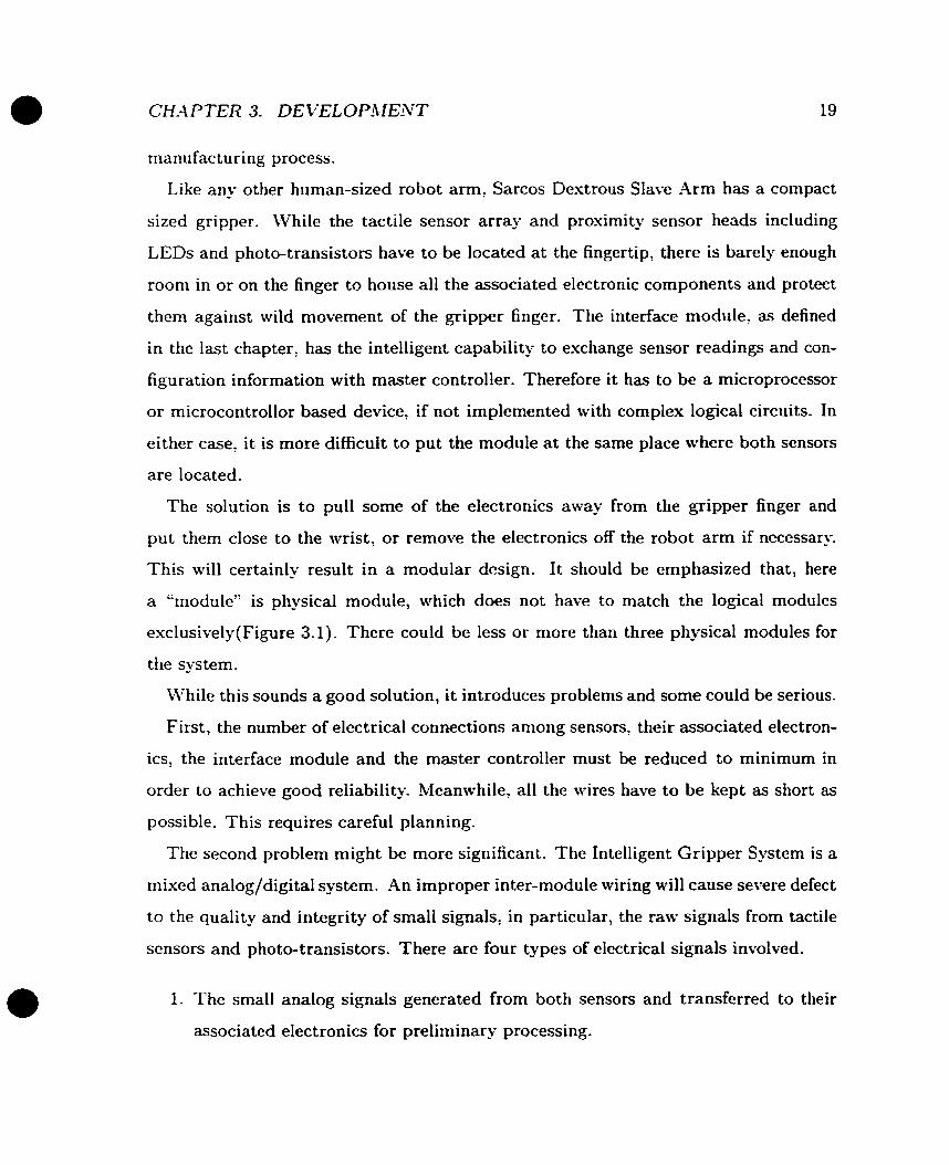
Following the design specification and rules, the overall modular architecture is estab-
lished as shown in figure 3.2.
Similar to functioning modularity, there are three physical modules. The tactile
sensing module, the proximity sensing module, and the interface module.
The tactile sensing module includes a tactile sensor arraÿ and its associated elec-
tronics. The task of the electronics is to preprocess tlie raw tactile information, to
multiplex and to de-multiplex. Al1 the relevant small signal processing is constrained
in this module. The entire module is a solid state device constructed frorn a base
Printed Circuit Board(PCB) and there is no out-of-PCB wiring.
The proximity sensing module is very sirnilar to the tactile sensing module. However,
due to the limited space on the finger tip, there are soft wirings between sensor
Interface and Control Module
Tactile Sensing Module
s 1 Associated Electronics I
Tactile A m y
Figure 3.2: Modular arc
Proximity Sensing Module
Associated Electronics
Ti-
iitecture for the Intelligent Gripper System
CH4 PTER 3. DE VELOPibfENT
\
2 x 2 Proximity Amy
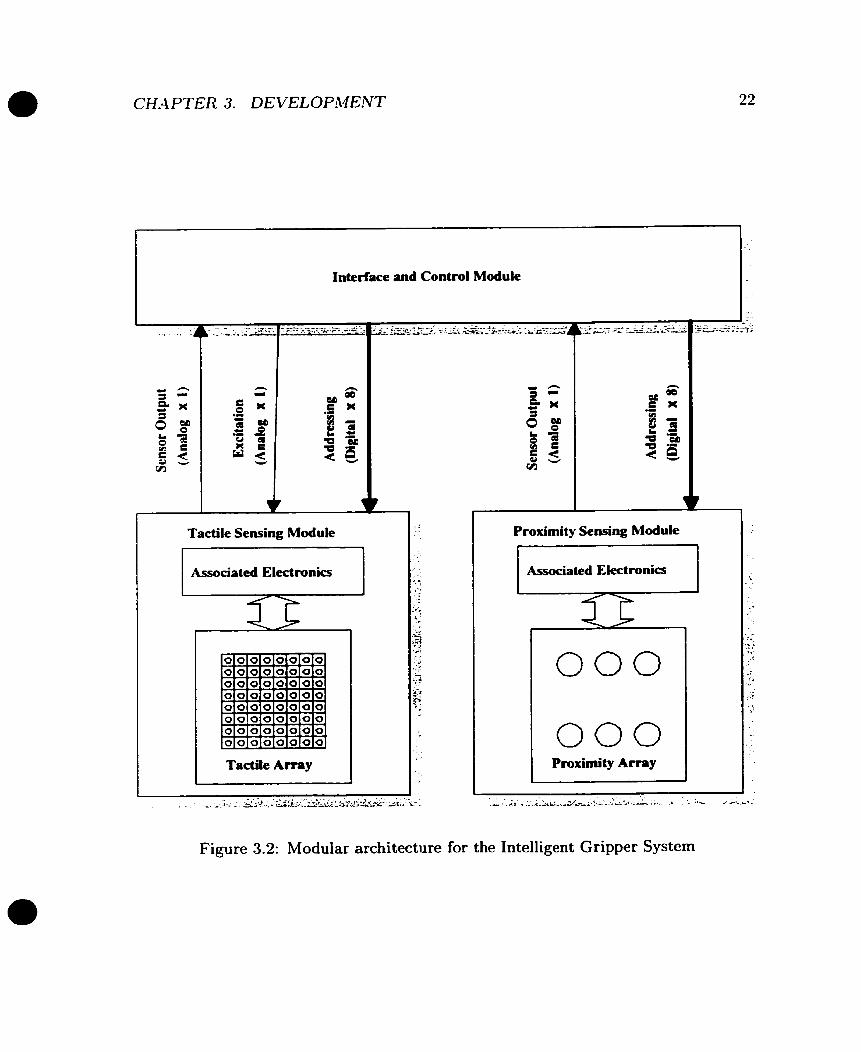
Figure 3.3:
I I 0.800"
d I
Layout of the gripper finger
Iieads and the c i r c u i t - Al1 the relevant small signal processing and multiplexing/de-
multiplexing are restrained in this module.
The interface module has the functionality defined in Chapter 2. It conducts the
control and the configuration to two sensing subsystems and converts sensing signals
from analog waveforms into digital data. Besides, this module has a part of the analog
circuitry for the tactile sensing subsystern. This part of the circuitry is mainly pre-A/D
converting processing, like gain and offset scheduling.
The analog and digital signals transmitted between three moduies are also shown
in figure 3.2.
Figure 3.3 is the physical layout of the gripper finger. In the center is a 8 x 8 tactile
sensing array. The four channel proximity sensors are located a t the four corners of the
finger. Instead of using one LED in each proximity sensor head, each LED is shared
by a pair of photo-transistors and is located in the middle of them. This configuration
saves the space and simplifies the circuits.
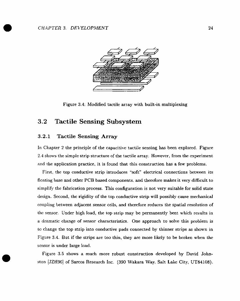
Figure 3.4: Modified tactile array with built-in multiplexing
3.2 Tactile Sensing Subsystem
3.2.1 Tactile Sensing Array
In Chapter 2 the principle of the capacitive tactile sensing has been esplored. Figure
2.4 show the simple strip structure of the tactile array However, from the experiment
and the application practice, it is found that this construction has a feu. problems.
First? the top conductive strip introduces "soft" electrical connections between its
floating base and other PCB based components, and therefore makes it very difficult to
simplify the fabrication process. This configuration is not very suitable for solid state
design. Second, the rigidity of the top conductive strip will possibly cause mechanical
cou pling between adjacent sensor cells, and therefore reduces the spatial resolu tion of
the sensor. Under high load, the top strip may be permanently bent which results in
a dramatic change of sensor characteristics. One approach to solve this problem is
to change the top strip into conductive pads connected by thinner strips as shown in
Figure 3.4. But if the strips are too thin, they are more Iikely to be broken when the
sensor is under large load.
Figure 3.5 shows a much more robust construction dcveloped by David John-
ston [JZH96] of Sarcos Research Inc. (390 Wakara \Va. Salt Lake City, UT84108).
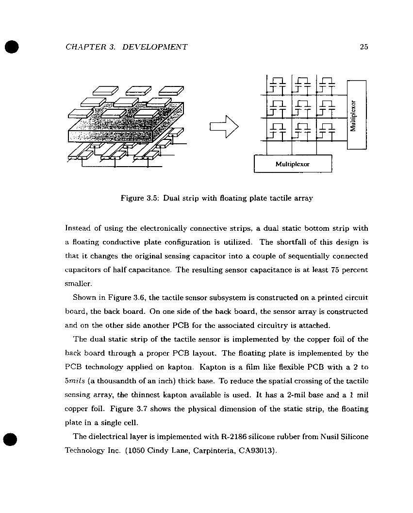
Multiplexor r--l Figure 3.5: Dual strip with floating plate tactile array
Instead of using the electronically connective strips, a dual static bottom strip with
a floating conductive plate configuration is utilized. The shortfall of this design is
that i t changes the original sensing capacitor into a couple of sequentially connected
capacitors of haif capacitance. The resulting sensor capacitance is at least 75 percent
smalIer.
Shown in Figure 3.6, the tactile sensor subsystem is constructed on a printed circuit
board, the back board. On one side of the back board, the sensor array is constructed
and on the other side another PCB for the associated circuitry is attached.
The dual static strip of the tactile sensor is implemented by the copper foil of the
back board through a proper PCB layout. The floating plate is implemented by the
PCB technology applied on kapton. Kapton is a film like flexible PCB with a 2 to
5mil.s (a thousandth of an inch) thick base. To reduce the spatial crossing of the tactile
sensing array, the thinnest kapton available is used. It has a 2-mil base and a 1 mil
copper foil. Figure 3.7 shows the physical dimension of the static strip, the floating
plate in a single cell.
The dielectrical layer is implemented with R-2186 silicone rubber from Nusil Silicone
Technology Inc. (1050 Cindy Lane, Carpinteria, C.493013).
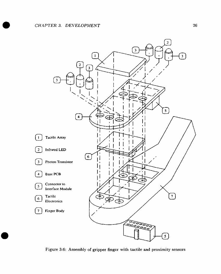
Figure 3.6: Assembly of gripper finger with tactile and proximity sensors

Via Hole
Dual Static Plates
Hoating Plaie
Figure 3.7: Physical dimension of a tactile ce11
.Above the floating plate layer and the kapton, there is an additional layer for protec-
tion and Electrical-hlagnetic (E14) shielding. -4s discussed earlier, the tactile sensor
electrodes, the two static strips, are directly connected to a higii impedance amplifier.
The tiny noise picked up by them will cause significant damage to the signal-noise
ratio. Theoretically, it is necessary to cover the entire sensor mith conductive and well
grounded material. One type of this shielding material is R-2637, also from Nusil.
However: esperiment shows there are shortfalls brought by the shielding layer and
more in-depth analysis will be presented in chapter 5.
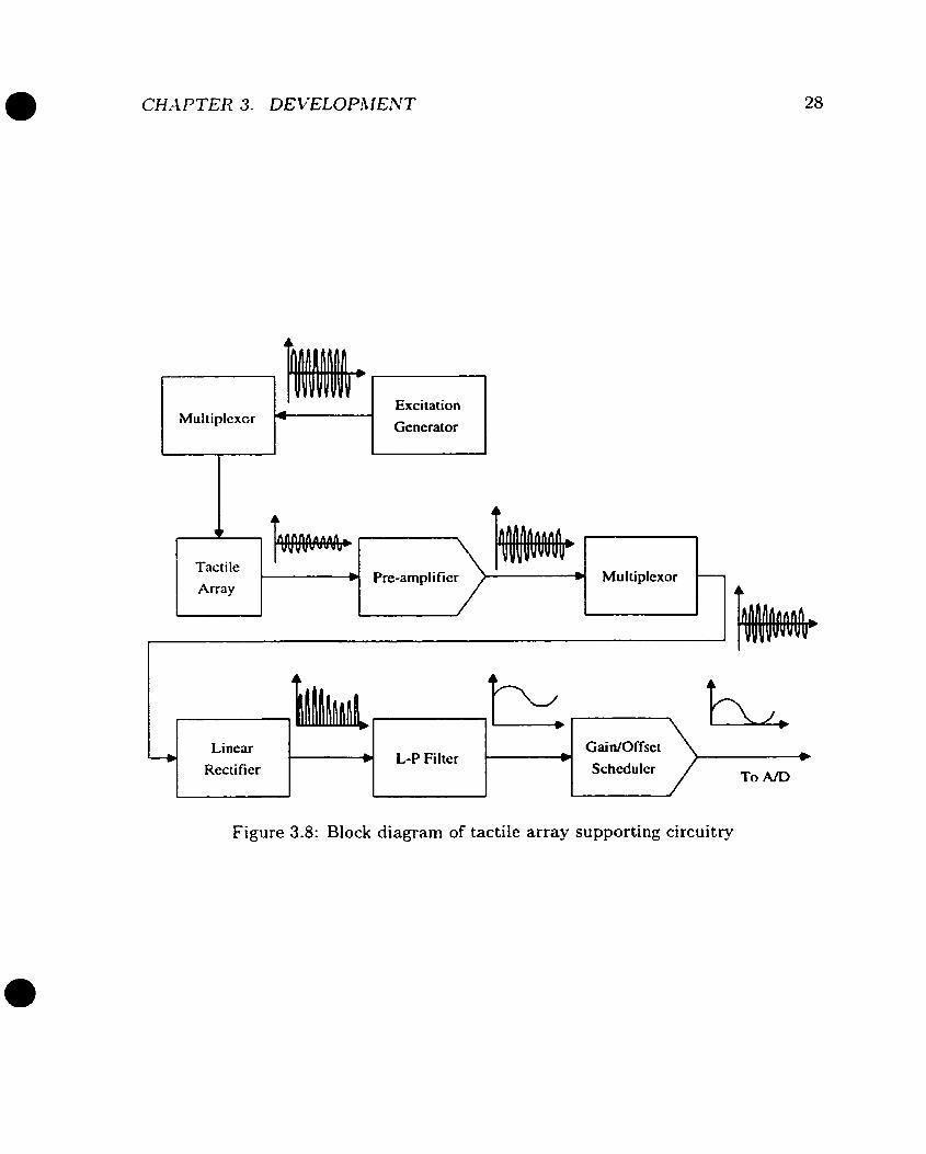
3.2.2 Tactile Sensing Electronics
Figure 3.8 is the block diagram of the supporting circuits of the tactile array
Each sensor ce11 has two connections, one for the excitation input and the other for
the sensor output. The system works in the serial manner in which only one sensor is
esci ted and sampled at one time. Therefore multiplexors are implementcd for both the
excitation and the sensor output. The device used is the CkIOS one-to-eight analog
Mu1 tiplexcr Excitation I 7 Generator
Li near GaidOffset 0 L-P Filter *
Rectifier Schcdulcr To A/D
Figure 3.8: Block diagram of tactile array supporting circuitry
switch ï4HC10-52. It has a low switching resistance of 50 Q.
There is a pre-amplifier associated to each row (eight in total) hefore the raw sensing
signals are rnultiplexed. T k reason not to multiples the raw current signal is because
its magnitude is very small while the multiplexor which behaves as a switch generates
h g e vide band noise. The signal-noise ratio will be catastrophically damaged if the
miiltiplesing is immediately applied to the sensor. The pre-amplifier acts as a buffer.
I t converts the raw sensing current into relatively large voltage n-hich is much easier
to handle.
Referring to Figure 8.2, the multiplexed sensor output is fonvarded to the linear
rectifier (U06C) where the AC voltage is converted to a DC signal, followed by a
Iow-pass filter (U06A). Before it is forwarded to the .4/D converter, the signal goes
through the offset scheduling circuit.
The tactile sensor response can be represented by this simplified model:
where \/, is the sensor response and x is the stimuli.
While the capacitance based tactile sensor output has a large offset b representing
the static (idle) capacitance, only the change of this capacitance is useful. If the
signal is directly sent to the 4 / D converter, a large part of the A/D resolution will
be wasted. This is especially true when the dynamic range of the sensor output is
relatively small compared to the offset. To solve the problem, an offset scheduling
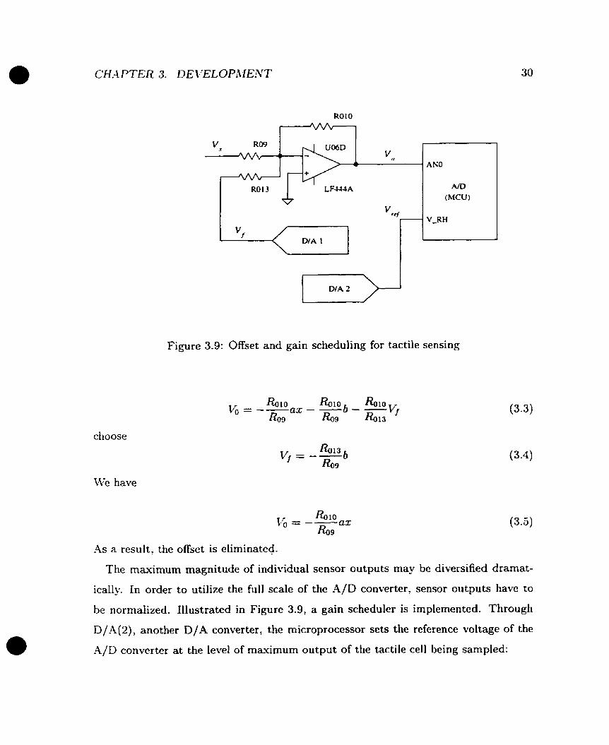
scheme is implemented as shown in Figure 3.9.
The output of D/A converter D/A(l) along with the raw sensor output are sent to
a subtracter (UOGD) which outputs
Ro 10 \ / O = -- R o i 0 \< - - &9 h l 3
Vf (3-2)
The microprocessor sends the calibrated offset value V, of the individual sensor ce11
through D/A(l ) . Combining 3.1, 3.2 becomes
choose
We have
ROlO
7
Figure 3.9: Offset and gain scheduling for tactile sensing
-4s a result, the offset is eliminated.
Tlie maximum magnitude of individual sensor outputs may be diversified drarnat-
ically. In order to utilize the full scale of the A/D converter, sensor outputs have to
be normalized. Illustrated in Figure 3.9, a gain scheduler is implemented. Through
D/..\(2), another D/A converter, the microprocessor sets the reference voltage of the
.4/D converter at the level of maximum output of the tactile ce11 being sarnpled:
The A/D reading is
The A/D reading is normalized.
The lOOKHz sinusoid excitation signal is generated by SR-2206, a universal signal
generator. According to Equation (2.2). the magnitude of the sensor output is propor-
tional to the excitation frequency. However, it can not be too higli due to the limited
bandwidth of the amplifier. The device used is an LF444 low noise OP amplifier
whose cut-off frequency is 2 M H z . lOOKHz is the trade-off frequency for optimized
performance.
Since there is only limited space on the gripper finger, only the sensor array, the
multiplesors and the pre-amplifiers are located on it. While the tactile sensor array is
at the contacting surface of the finger, al1 the other components are located on a srnall
PCB which is attached on the back of the base PCB and embedded in the body of the
finger. This structure not only gives greater physical protection but more importantly,
shields the small signal electronics against elect rical and magnetic contamination.
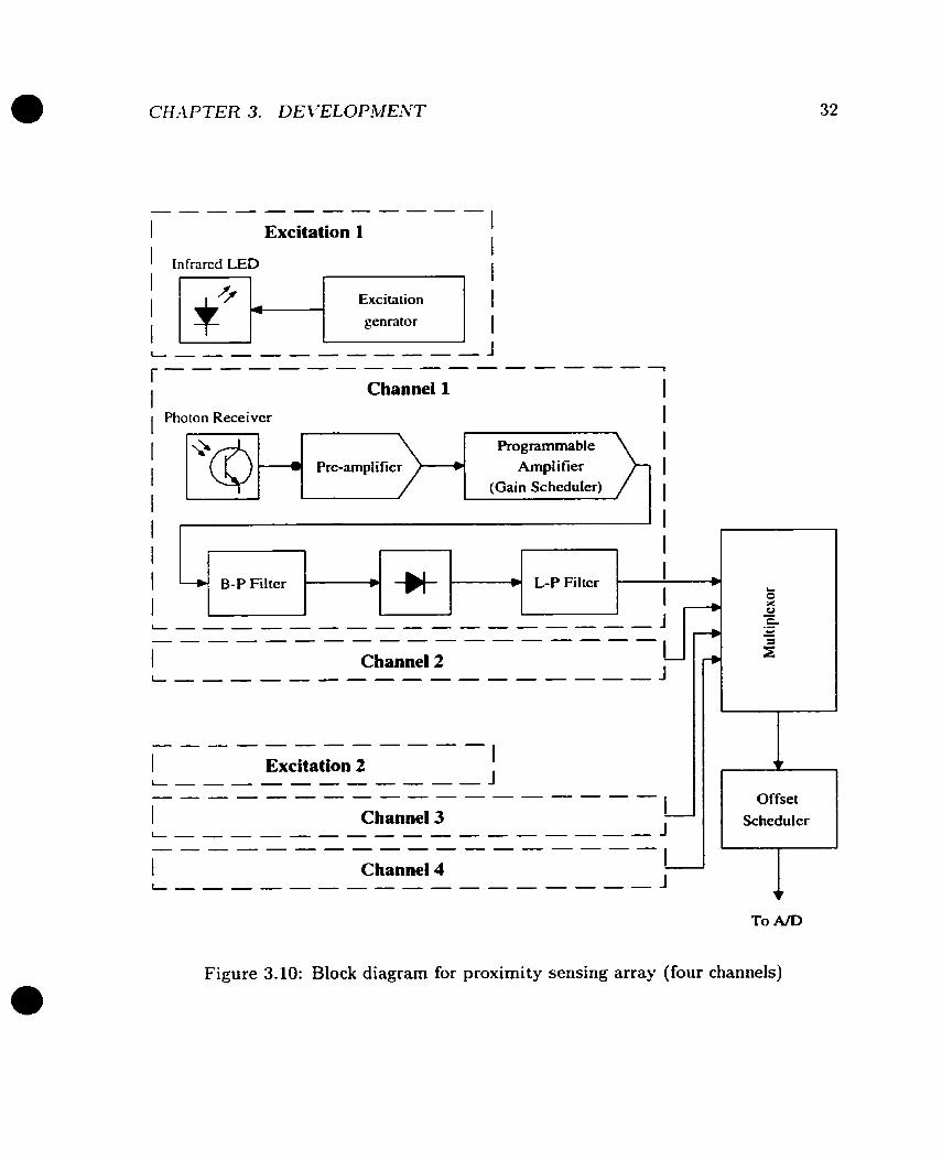
3.3 Proximity Sensing Subsystem
Figure 3.10 shows the block diagram of the circuitry supporting a 2 x 2 infrared LED-
photon-transistor prosimity sensing array- Essentially, the entire signal processing is
similar to that of the tactile subsystem.
Each proximity channel has its own pre-amplifier in order to reduce switching noises
caused by the rnultipiexor. In contrast to the tactile excitation, the LED is driven
independentlÿ and each LED is shared by a pair of sensing devices. This configuration
simplifies the design by utilizing the active nature of this type of sensing devices. The
1 Excitation 1
Excitation genrator
Channel 1
Photon Receiver
Programmable 1 Pre-ampli fier +I Arnpl i fier
(Gain ScheduIer) I I
4 I -+ B-P Filter wub + L-P Filter 1 +
I L.
2 A f - O
C
------------------ 1 Channel 2 !J
1 Channel 3 L - J
Figure 3.10: Block diagram for proximity sensing array (four channels)
-
.- - 4
- s
w
Offset Scheduler
v
Distance
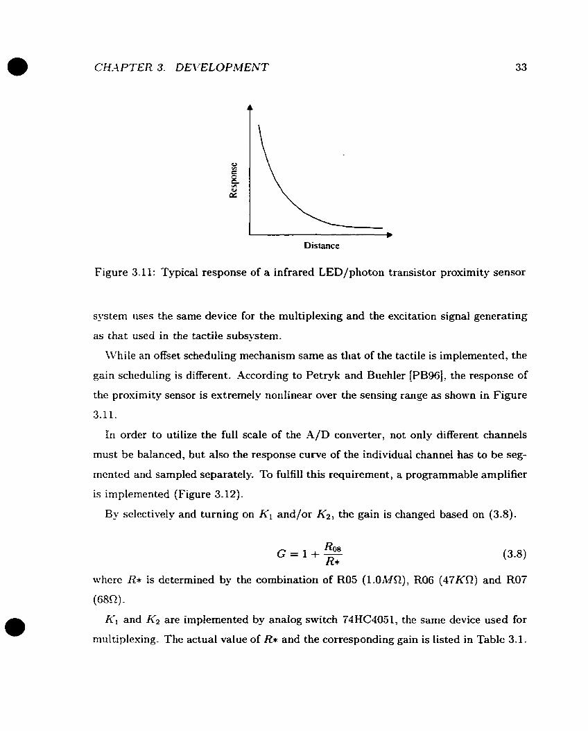
Figure 3.11: Typical response of a infrared LED/photon transistor proximity sensor
systern uses the same device for the multiplesing and the excitation signal generating
as that used in the tactile subsystern.
\\?hile an offset scheduling mechanism same as that of the tactile is implemented, the
gain scheduling is different. .4ccording to Petryk and Buehler [PB96], the response of
the prosimity sensor is extremely norilinear over the sensing range as shown in Figure
3.11.
In order to utilize the full scale of the A/D converter, not only different channels
must be balanced, but also the response curve of the individual channel has to be seg-
mented and sampled separately. To fulfill this requirement, a programmable amplifier
is implemented (Figure 3.12).
By selectively and turning on K I and/or K2, the gain is changed based on (3.8).
where R* is determined by the combination of R05 (l.OMQ), R06 (47KR) and Roi
(68C2).
KI and K2 are implemented by analog switch 74HC4051, the same device used for
multiplexing. The actual value of RI and the corresponding gain is listed in Table 3.1.
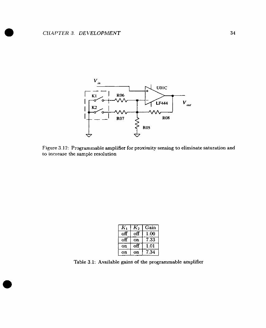
Figure 3.12: Programmable amplifier for proximity sensing to eliminate saturation and to i~icrease the sample resolution
Table 3.1 : Available gains of the programmable amplifier
Reset in high gain rnodc:
I
I Set in low gain mode I
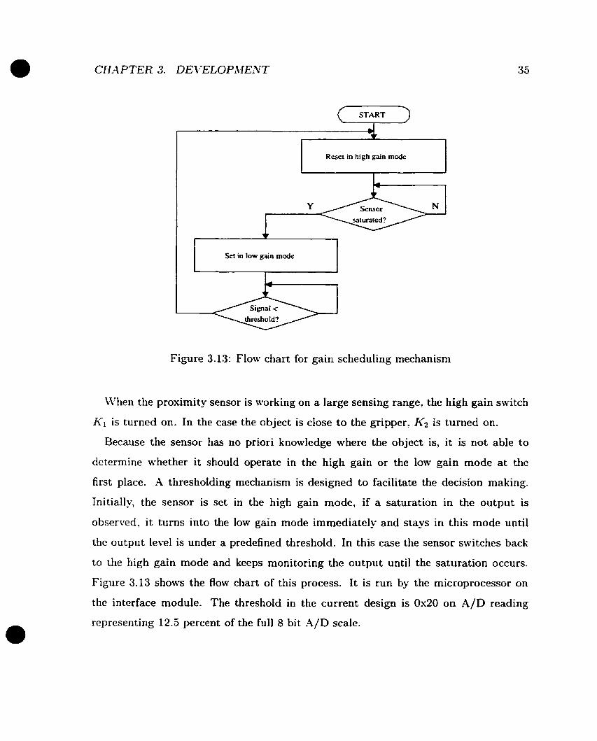
Figure 3.13: Flow chart for gain scheduling mechanism
When the proximity sensor is working on a large sensing range, the high gain switch
KI is turned on. In the case the object is close to the gripper, K2 is turned on.
Because the sensor has no priori knowledge where the object is, it is not able to
determine whether it should operate in the high gain or the low gain mode a t the
first place. A thresholding mechanism is designed to facilitate the decision making.
Initially, the sensor is set in the high gain mode, if a saturation in the output is
observed, it turns into the low gain mode immediately and stays in this mode until
the output level is under a predefined threshold. In this case the sensor switches back
to the high gain mode and keeps monitoring the output until the saturation occurs.
Figure 3.13 shows the flow chart of this process. It is run by the microprocessor on
the interface module. The threshold in the current design is 0x20 on A/D reading
representing 12.5 percent of the full 8 bit .4/D scale.
3.4 Interface Module
3.4.1 Architecture
Logically, the interface module is the "brain" of the entire Intelligent Gripper System.
It coordinates the operation of both sensor subsystems and regulates the data flow
bet~veen thern and the master controller.
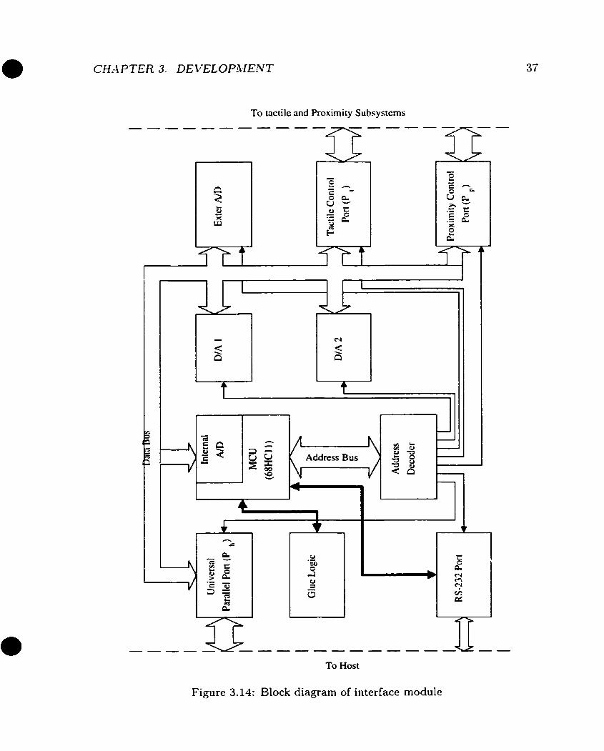
Figure 3.14 shows the functionai block diagram. The centra1 part is MC68HCf lE2,
an eight-bi t micro-controller (MCU) . Al1 the other components are essentially peri-
pheral devices connected to it through the data bus, the address bus, and the control
signals.
The hlC68HCllE2 has an interna1 2KB EEPROM (Electrical Erasable Program-
mable Read Only Memory) and a 256-byte RAM bay. These memory resources are
adequate to implement the application software through proper coding. Currentlx
there is no external ROM and RLZhl installed. The MC68HCllE2 has four opera-
tional modes selected by MOD-4 and MODB pins. They are listed in Figure 3.20.
Two modes may be activated in the current design. The special boot strap mode
is only for EEPROM programming and/or updating. Under the normal situation,
the micro-controller is operating in normal extended mode in which more external
peripheral devices can be supported.
Pt is an eight-bit unidirectional output parallel port which is used to latch the
niultiplesor input commands issued by MCU to the tactile sensing subsystem. -4ny of
the sensor cells in the array can be addressed (excited and sampled) by writing the
proper octet to Pt- Figure 3.15 shows the mapping between the address and actual
cells.
P, serves the similar role as Pt does for the four-channel proximity sensing subsys-
tem. In addition to sensor addressing, the gain scheduler is also controlled by MCU
through P,.
Both Pt and P, are implemented by 74HC3740 UOlO and UOl 1 respectively, as shown
To tactile and Proximity Subsystcms
To Host
Figure 3.14: Block diagram of interface module

CH.4 PTER 3. DEVELOPA.IENT
Top Front
O 1 2 3 4 5 6 7
Figure 3.15: Tactile ce11 address mapping (top view)

CH-M'TER 3. DEVELOPMENT
Signai S 1 'ame OSTR GKD
MODB hl1 O DA RESET
IHS OHS ISTR D W )
11 I Output I
Pin Number 1
2 to 6 T 8 9 10
I
12 I Output I
Direction Input 3 -4
Input (Set to high/low internally) Input (Set to high/low internally)
Input (Set to high internally) Input
Table 3.2: List of signals of host interface Pm
in Figure B.2
Pm is a universal parallel port used to communicate with the master controller.
It lias an eight bit bi-directional data bus and five control signals for hand-shaking.
M'hile the data bus is implemented witli 74HC24-I and 74HC374 (U021 and ü020 in
Figure B.3). the control signals use general purpose 1/0 lines of the MCü and they
can be configured either as input or as output. Figure 8 . 3 shows the schematics of
Pm and Table 3.2 lists the names and directions of the control signals. Notice MODA,
MODB and RESET are only used by the master controller for reset and initialization.
Figure 3.16 gives the bus/hand-shaking cycles for Pm read and write operations.
D/.4(1) (U07) and D/A(2) (U08) are eight bit digital to analog converters -4D558.
They are used for gain and offset scheduling for both sensing subsystems. as described
earlier. Thesc devices are U P compatible, therefore no additional component is needed
to interface with MCU (Figure 3.17).
-4ccording to the design functionality and specifications, the interface module must
send sensor readings to the master controller only in the digital format. Therefore, al1
the analog signals from sensors must be digitized in thc interface module. Fortunately,
G8HCll cornes with an interna1 8-bit A/D converter. It has the minimum converting
time of 20ps. Considering the sub one liundred bandwidth of a typical robot system,
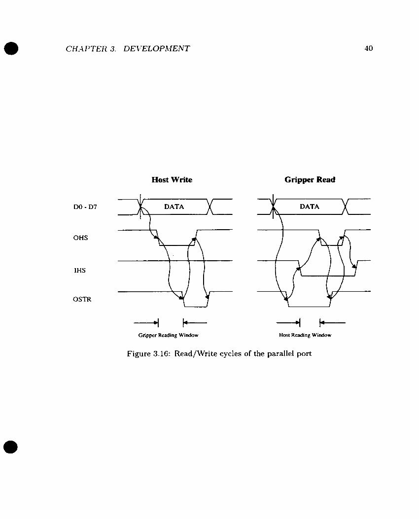
DO - D7
OHS
IHS
Host W rite Gripper Read
OSTR
--+ t-- Gripper Reading Window
Figure 3.16: Read/\Vrite cycles
-+ i t-- Host Reading Window
the parallel port

Figure 3.17: Interface between AD558 and MCU
i t is adequate to serve this purpose. .4n external Il-bit UP compatible .4/D converter
AD7871 (U09) is also ernployed (Figure 3.18) in case eight bit resolution is not high
enough for analysis.
MC68HC11 has its internal serial communication port (SCI) complying with the
RS232 format. While this port can be activated by the application for data collect-
ing/transmitting, it serves a more critical role to let users download programs into
EEPROM. -4 voltage translator M.4X202 is employed to translate MC68HCll's TTL
level to RS232 level and vice versa.
The only address space available for 68HCll is the memory space. Al1 the parallel
ports. D/A devices and esternal A/D devices are mapped into this space through
the address decoder (U02 in Figure B.1). Table 3.3 lists the addresses of al1 external
devices. The access to the internal A/D and serial port is through dedicated instruc-
tions. Therefore, they are not mapped in this space.
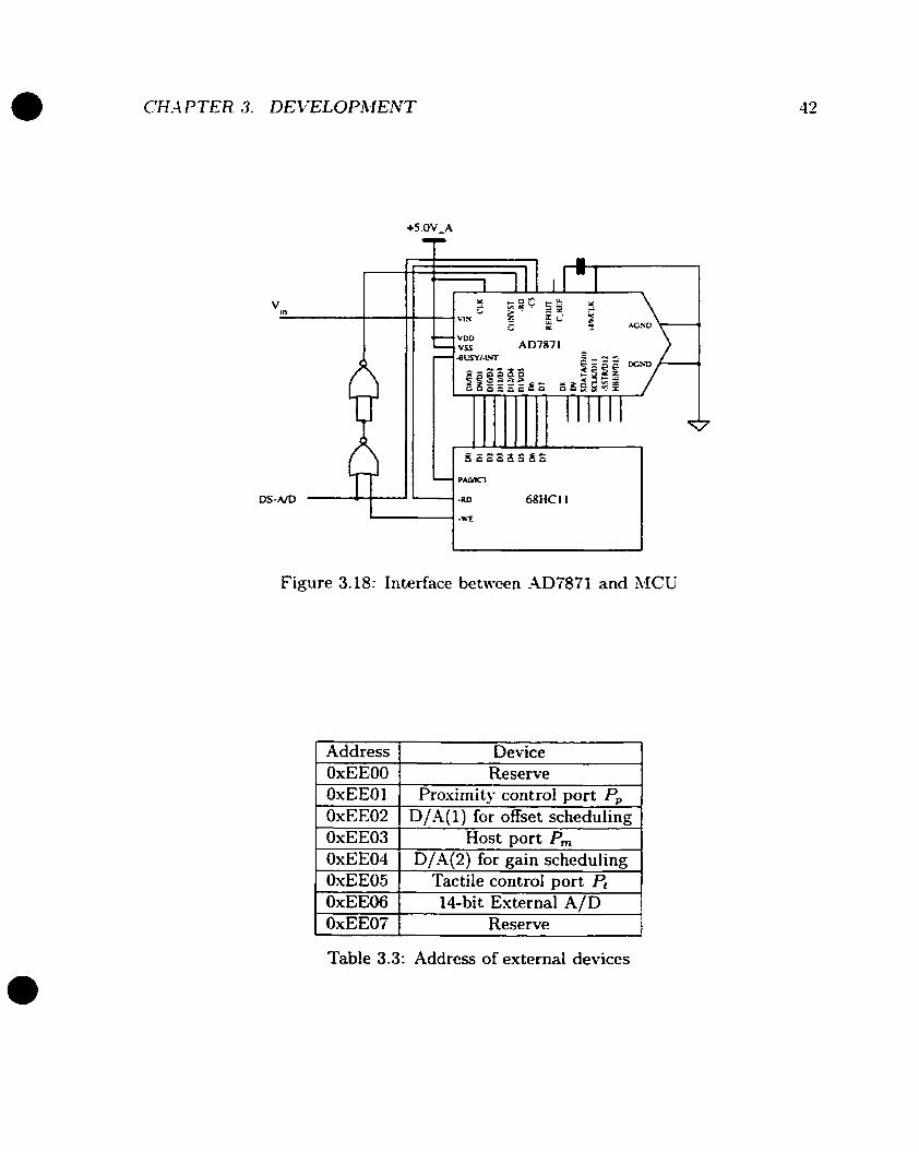
Figure 3.18: Interface between -4D7871 and MCU
Address 1 Device
1 OxEEO6 1 1
14-bit External A/D 1
OxEEOO OxEEOl OxEE02 OxEE03 OxEE04 OxEE05
Reserve 1
Reserve Proxirnity control port P,
D/.4(1) for offset scheduling Host port Pm
D/A(2) for gain scheduling Tactile control Dort P,
Table 3.3: Address of external devices
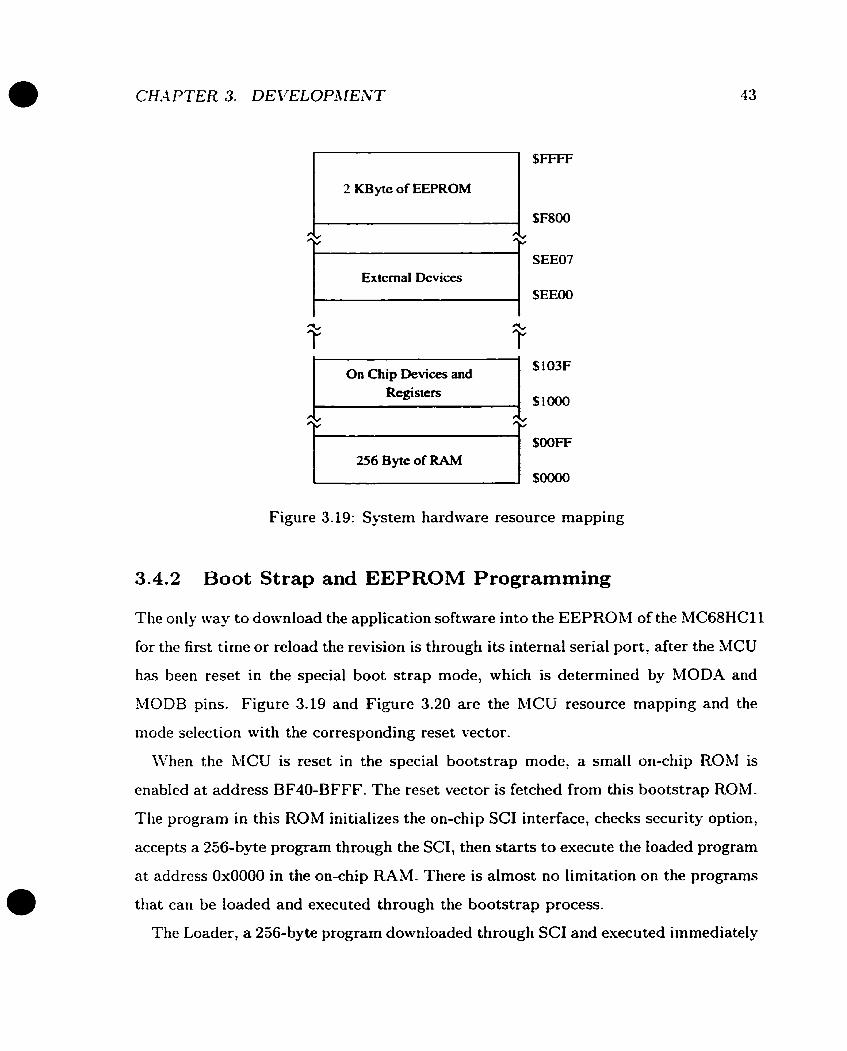
SFSOO
SEEO7 Extemal Devices kl SEEOO
Registe rs , $Io00
256 Byte of RAM
b J
On Chip Devices and
Figure 3.19: Sÿstem hardware resource mapping
S103F
3.4.2 Boot Strap and EEPROM Programming
The only way to download the application software into the EEPROM of the MC68HC11
for the first time or reload the revision is through its interna1 serial port, after the MCU
has been reset in the special boot strap mode, which is determined by MOD-4 and
h4ODB pins. Figure 3.19 and Figure 3.20 are the MCU resource mapping and the
mode selection with the corresponding reset vector.
IVhen the MCU is reset in the special bootstrap mode, a small on-chip ROM is
enabled at address BF40-BFFF. The reset vector is fetched from this bootstrap ROM.
The program in this ROM initializes the on-chip SC1 interface, checks security option,
accepts a 256-byte program through the SCI, then starts to execute the toaded program
at address 0x0000 in the on-chip RAM. There is almost no limitation on the programs
that can be loaded and executed through the bootstrap process.
The Loader, a 256-byte program downloaded through SC1 and executed immediately
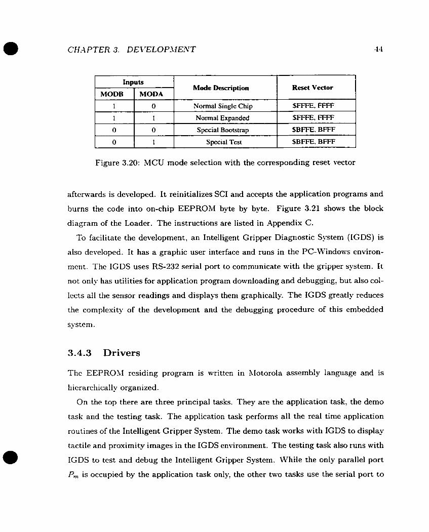
Inputs Mode Description Reset Vector
Figure 3.20: MCU mode selection with the corresponding reset vector
1
I
O
O
afterwards is developed. It reinitializes SC1 and accepts the application programs and
burns the code into on-chip EEPROM byte by byte. Figure 3.21 shows the block
diagram of the Loader. The instructions are listed in Appendiu C.
To facilitate the development, an Intelligent Gripper Diagnostic System (IGDS) is
also developed. It has a graphic user interface and runs in the PC-Windows environ-
ment. The IGDS uses RS-232 serial port to communicate with the gripper system. It
not only has utilities for application program downloading and debugging, but also col-
lects al1 the sensor readings and displays them graphically. The IGDS greatly reduces
the complesity of the development and the debugging procedure of this embedded
system.
3.4.3 Drivers
O
1
O
1
The EEPROM residing program is written in hlotorola assembly language and is
hicrarchically organized.
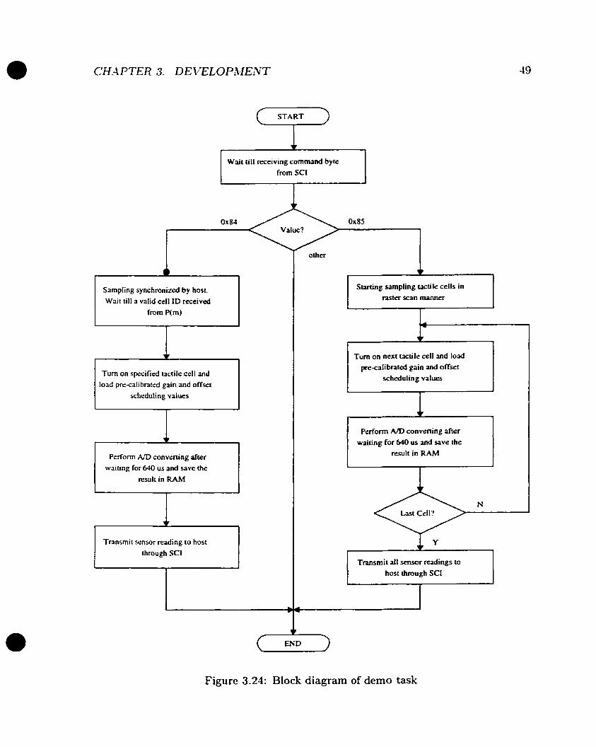
On the top there are three principal tasks. They are the application task, the demo
task and the testing task. The application task performs al1 the real time application
routines of the Intelligent Gripper System. The demo task works witli IGDS to display
tactile and prosimity images in the IGDS environment. The testing task also runs with
IGDS to test and debug the Intelligent Gripper System. While the only parallel port
Pm is occupied by the application task only, the other two tasks use the serial port to
Normal Single Chip
Normal Expanded
Special Boorstrap
Special Test
SFFFE, FFFF
SFFFE, FFFF
SB=. BFFF
SBFFE. BFFF

CH-4PTER 3. DEVELOPMENT
Initiolize SC1 and wait ri11 0x73 receivrd
Wait till octet received and 1
set "Lasi Linr" flog 1
Wait till receive one byte of "Length of the Linc"
Wait UII reseive IWO bytes of stvting address
into EEPROM. Increment addrcss by I
is loadrd
Send the content of al1 rcgisiers io host (64 octcrs) 1
Figure 3.21: Block diagram of Loader
CH.4 PTER 3. DE VELOPhIENT 46
cschange sensor readings and control parameters with IGDS.
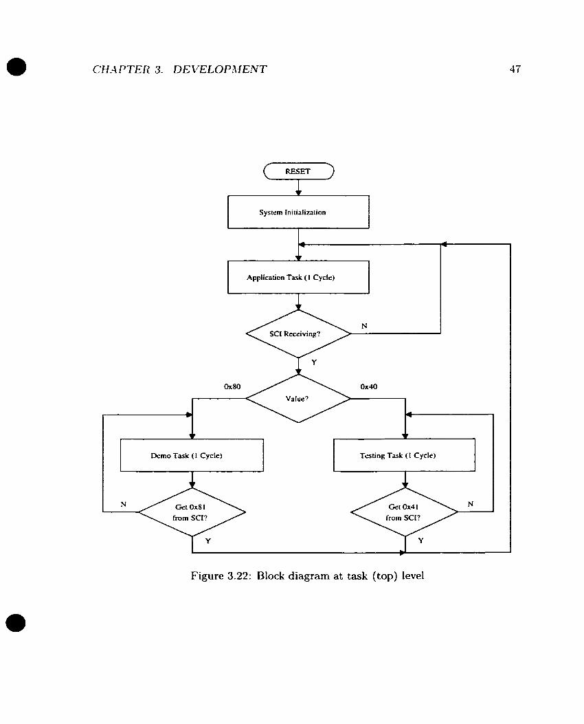
By dcfault, the system starts the application task after the reset. It is branched
into the demo task or the testing task at any time after the MCU receives branch
command octet (Os80 in demo task, Os40 in testing task) through SCI. The program
alu-ays returns to the application task as soon as LlCU receives termination comrnand
octet (Os81 in demo task, 0x41 in testing task).
Figure 3.22 shows the top level block diagram. Figure 3.23, Figure 3.24 and Figure
3.25 are block diagrams of the interna1 structure and organization of the three principal
tasks. The list of assembly code can be found in Appendix C.
Application Task ( 1 Cycle) e
Demo Task ( 1 Cycle) c Trsting Task ( 1 Cycle) c r
Figure 3.22: Block diagram at task (top) level

START (7 Wait till r ~ ~ e i v i n g command byte
from P(m) 1 Smpl ing synchronized by host. Wait till a valid ce11 ID m e i v e d
from P(m)
Turn on specified tactik cell and loîd prc-calibntd gain and offset
scheduling values
+ Perform A/D convming a f ~ e r
waiting for 64û us and save ihe result in RAM
Staning sampling ucüle cells in -ter scan m m n a
Turn on nexi mt i i e ce11 and load pre-calibnted gain and offset
schduling values
Perform An> convening afirr waiüng for 640 us and save the
msult in RAM
T m r n i t a11 scnsor rcadings to host through P(m)
Figure 3.23: Biock diagram of application task
CH-4 PTER 3. DE VELOPILIEVT
Wait till receiving cornrnand byte r frorn SCI
Value? r?- h Sampling synchronized by hosi.
Wait tilt a valid cell ID received
from P(m)
Tum on spcified tactile cell and load pre-calibnted gain and offset
scheduling values
Pcrform A/D convening afrer
waiting for 640 us and save the
result in €€AM
Transmit sensor rrading io hosr
ihrough SC1
Surcing smpl ing tactile cells in m t e r scan manner
Tum on next tactile cell and lo3d
pre-calibnid gain and offset schduling values
P r r f m A D convening after
waitinp for 640 us and save the m u l t in R A M
Transmit d l sensor radings to
host t h ro~gh SCI I END
Figure 3.24: Bloclc diagram of demo task
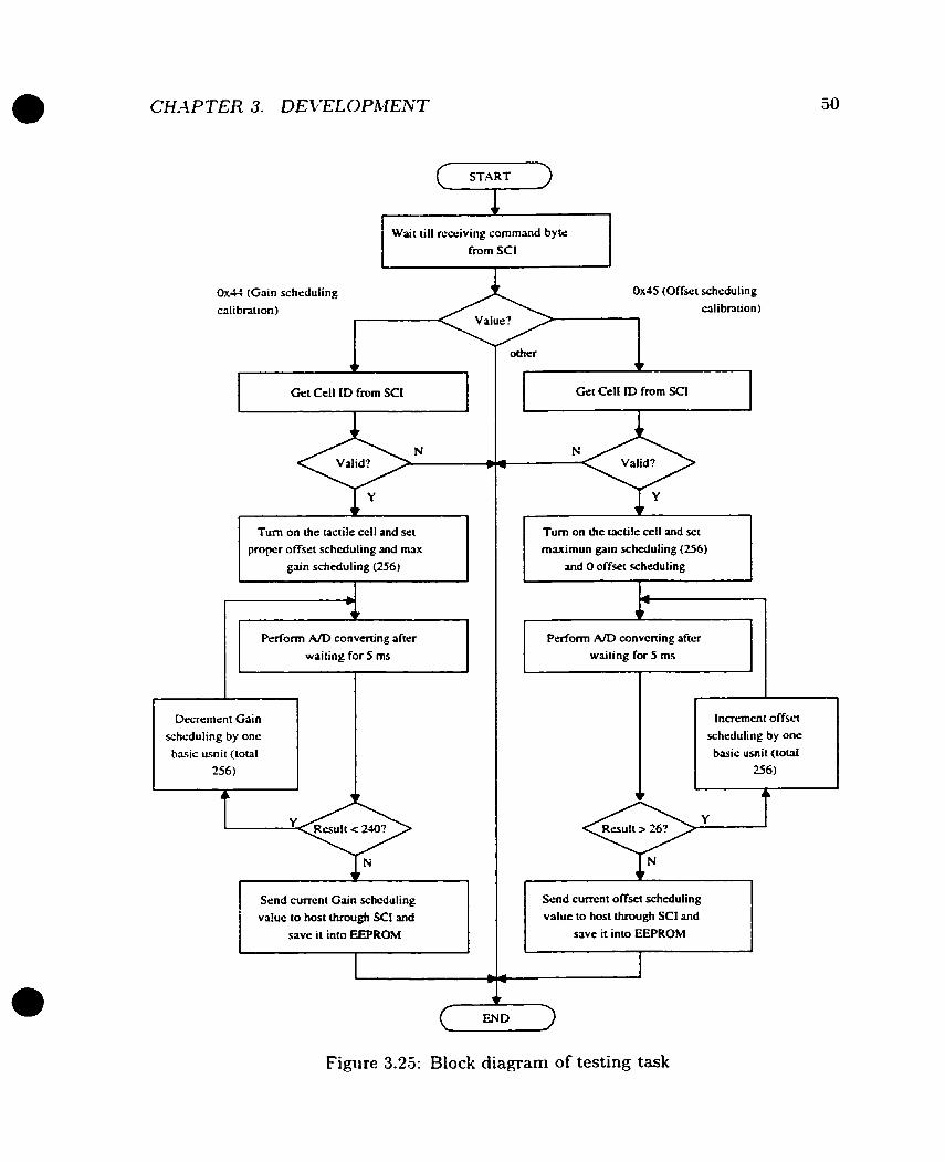
0 x 4 1 (Gain scheduling
calibraiion)
Turn o n the wctile cell and x t proper offset scheduling and rnax
S T ART
Wait till rcceiving command byte from SC1
0x45
I I
14
R 4
Perfonn A/D converthg d t e r
waiting for 5 ms
Decrement Gain 1 1 scheduling by one
basic usnit (total 1
Send current Gain scheduling value to host through SC1 and
save it into EEPROM
(Offset scheduling
calibralion)
o t h a ,
Turn on h e wctile cefl and set maximun gain scheduling (256)
I waiting for 5 ms
I 1 Innement offset
I 1 scheduling by one basic usnit (totai 1 L
Send cunent offset scheduling value to host through SC1 and
Save it inio EEPROM
END
Figure 3.23: Biock diagram of testing task
Chapter 4
Experimentation
The experimentation on the Intelligent Gripper System is composed with two aspects.
First is the testing and the verification. The major objectives of this part of the ex-
periment are to verif'; the effectiveness of the various design strategies, and to fully
understand the behavior of the system and sensing devices which are difficult to be
precisely modeled and predicted. The second aspect is the demonstration of the po-
tential application of the system. Since this thesis is mainly focusing on fundamental
issues on the design and the implementation, the dernonstration of the application mil1
be relatively preliminary. Besides, the proximity sensor implemented in the current
system is modified from the device developed by Petryk and Buehler which has been
fully investigated [PB96]. The work described in this chapter is mainly about the
tactile sensing subsystem.
4.1 Tactile Sensor Characterization
To understand and mode1 the tactile sensing subsystem, both mechanical and elect rical
properties have to be identified. The mechanical properties include static, dynamic
and spatial properties. The electrical properties include the sensor signal/noise ratio
and the sampling rate.

Linear Motor (Brucl & Kjar)
Accekromrter (BrueI & Kjar)
Figure 4.1: Experimental setup
4.1.1 Experiment Setup
The esperimental setup is shown in Figure 4.1. -4 flat palm tactile sensing array
identical to which is used in the Intelligent Gripper System is used for testing. A
transversed Bruel & Kjaer voice coi1 linear motor on the top enerts force ont0 a tactile
sensor ce11 through a 2.5rnm diameter probe. The tactile array is located under the
probe by a three DOF Cartesian stage. A combined LVDT-LVT rneasures the position
and the velocity of the probe. A Bruel & Kjaer force sensor installed between the probe
and the motor shaft rneasures the applied force and a Bruel & Kjaer accelerometer
installed right above the force sensor measures the linear acceleration. The vertical
position of the probe is controlled by an analog PD controller with an digital input
for set point commands.
The mechanical bandwidth of the system is determined by the motor whicii is around
50Hz. The sampling and control are provided by a Micron P9O persona1 computer
running Labview software, through a ComputerBoards analog 1/0 board with 8 chan-
nels of 16-bit A/D and 2 channels of 12-bit D/A. The maximum system sampling rate
is close to 4.5KH.z .
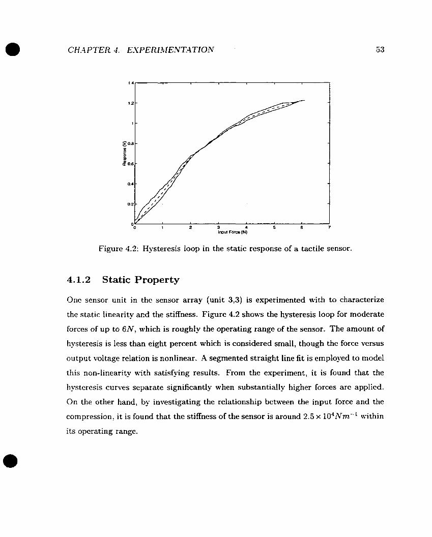
Figure 4.2: Hysteresis loop in the static response of a tactile sensor.
4.1.2 Static Property
One sensor unit in the sensor array (unit 3,3) is experimented with to characterize
the static linearity acd the stiffness. Figure 4.2 shows the hysteresis loop for modcrate
forces of u p to 6 N , which is roughly the operating range of the sensor. The amount of
hysteresis is less than eight percent which is considered small, though the force versus
output voltage relation is nonlinear. A segrnented straight line fit is employed to mode1
this non-linearity with satisfç-ing results. From the experimcnt, it is found that the
hysteresis curves separate significantly when substantially higher forces are applied.
On the other hand, by investigating the relationship between the input force and the
compression, it is found that the stiffness of the sensor is around 2.5 x 10⁴iVm-' within
its operating range.

4.1.3 Dynamic Property
A single tactile ce11 can be modeled as a second order mechanical system:
where x and y are the sensor response and the input force respectively, and stiffness
XI has alrcady been identified. In the esperiment, the probe and the sensor unit have
been kept well contacted. The input force measurement is made from the load cell.
Therefore the mass m is the total mass of the floating part of the sensor unit and the
mass of the probe plus the half of the loadcell which can be precisely measured. The
floating part of the sensor includes the floating pad and the top shielding rubber layer.
The dielectric rubber layer is very thin and its mass is ignored.
Using the Matlab System Identification Toolbos, it is found the system damping is
1.3 x 10²Nsm-' while the sensor mass is no larger than 0.05g. This is an estremely
over damped system and the projected bandwidth is 220Hz . The swept sine test
resuited in a flat response which indicates that the sensor is well beyond the 5OHz
bandwidth of the actuator.
4.1.4 Spatial Property
The spatial property of the tactile sensor is basically the crossing response over sensor
cells in a close neighborhood. To identify this property, the probe is scanncd across
the surface whiie the response of a single tactile ce11 is monitored. Figure 4.3 shows
this response in respective to the x-dimension scanning. The contiguous changes of the
sensor response with the probe position are due to underlying continuum mechanics
of the rubber layers.
One of the most significant applications of tactile sensing is the object localization.
To pinpoint more finely the location of the probe, a weighted averaging of responses
of neighboring sensor cells scheme is applied:
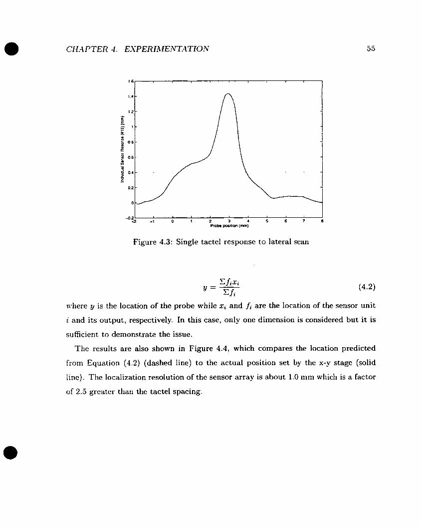
Figure 4.3: Single tactel response to lateral scan
where y iç the location of the probe while xi and fi are the location of the sensor unit
i and its output, respectively. In this case, only one dimension is considered but it is
sufficient to demonstrate the issue.
The results are also shown in Figure 4.4, which compares the location predicted
frorn Equation (4.2) (dashed line) to the actual position set by the x-y stage (solid
line). The localization resolution of the sensor array is about 1.0 mm wliich is a factor
of 2.5 greater than the tactel spacing.
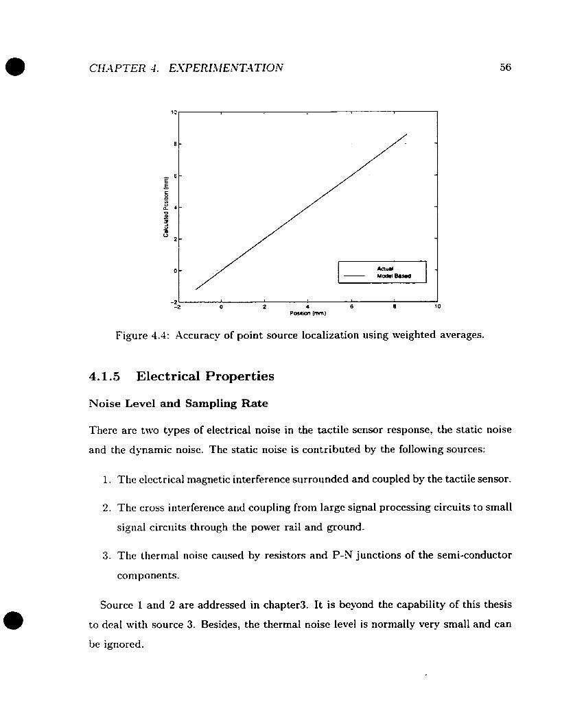
Figure 4.4: Accuracy of point source localization using weighted averages.
4.1.5 Electrical Properties
Noise Level and Sampling Rate
There are two types of electrical noise in the tactile sensor response, the static noise
and the dynamic noise. The static noise is contributed by the following sources:
1. The electrical magnetic interference surrounded and coupled by the tactile sensor.
2. The cross interference and coupling from large signal processing circuits to small
signal circuits through the p o w r rail and ground.
3. The thermal noise caused by resistors and P-N junctions of the serni-conductor
components.
Source 1 and 2 are addressed in chapter3. It is beyond the capability of this thesis
to dcal with source 3. Besides, the thermal noise Ievel is nornlally very small and can
be ignored.
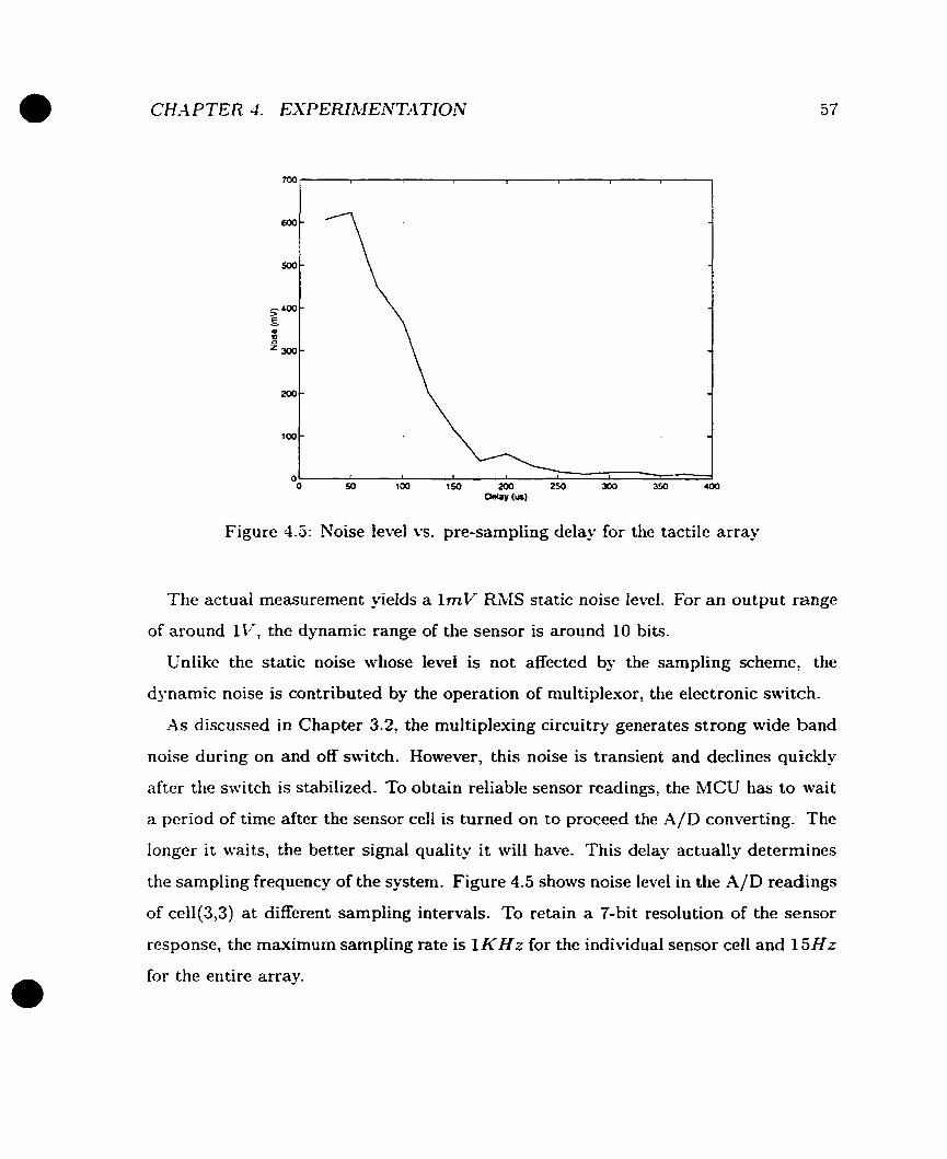
Figure 4.5: Noise level vs. pre-sampiing delay for the tactile array
The actual measurement yields a 1mV RMS static noise level. For an output range
of around IV, the dynamic range of the sensor is around 10 bits.
Unlike the static noise whose level is not affected by the sampling scheme, the
dynamic noise is contributed by the operation of multiplexor, the electronic suitch.
As discussed in Chapter 3.2, the multiplexing circuitry generates strong wide band
noise during on and off switch. However, this noise is transient and declines quickly
after the switch is stabilized. To obtain reliable sensor readings, the MCU has to wait
a period of time after the sensor ce11 is turned on to proceed the A/D converting. The
longer it waits, the better signal quality it will have. This delay actually determines
the sampling frequency of the system. Figure 4.5 shows noise level in the A/D readings
of ce11(3,3) a t different sampling intervals. To retain a 7-bit resolution of the sensor
response, the maximum sampling rate is l K H r for the individual sensor ce11 and 1 5 H z
for the entire array.

CH.4 PTE R 4 . E S P ERIAIEArT-4 TION 58
Non-conductive silicone which is identical to that used for the dielectric layer (R-2186).
Table 4.1: List of tactile arrays using different shielding materials
'
Sensor #l Sensor #2 Sensor $ 3 9
In the case where on1y one sensor ce11 is being used, the dynamic noise doesn't exist
since there is no switching activity
Xormal conductive silicone with silver cornpourid (R-2937)- Newly forrnulated conductive silicone with silver-aluminum
c o m ~ o u n d (LSR-9923).
The Shielding Rubber Layer
The tactile sensors are covered by a conductive silicone layer. The purpose to adopt
this layer is based on the assumption that the electrical-magnetic interference caused
by rnetal objects which touch the sensor may introduce a large amount of noise into
the scnsor readings or even cause the sensor to malfunction.
To investigate how serious this interference could be and what the effectiveness of
the shielding layer is, five tactile arrays using three different types of materials for
outer-most layer (shielding) have been fabricated and tested (Table 4.1):
The results show sensor #1 has a reasonably good static response on metal objects-
However, its performance decays over a short period of time. Four months later, the
response on metal objects becomes completely random and the cross talk between
individual sensor cells is radical on a global basis (Figure 4.G).
Sensor #2 and #3 essentially behave very much similarly as sensor #l does. They
fail to have any noticeable improvement over sensor #I .
Surprisingly, sensor #4 and #5 have a very good and long-lasting performance
(Figure 4.7). First, there has been no noticeable difference observed in noise level
when they handle metal objects or non-metal objects (plastic in this case). This
provides the evidence that under the current design, the electro-magnetic interference
is actually not as bad as originally anticipated. Second, these two sensors are about
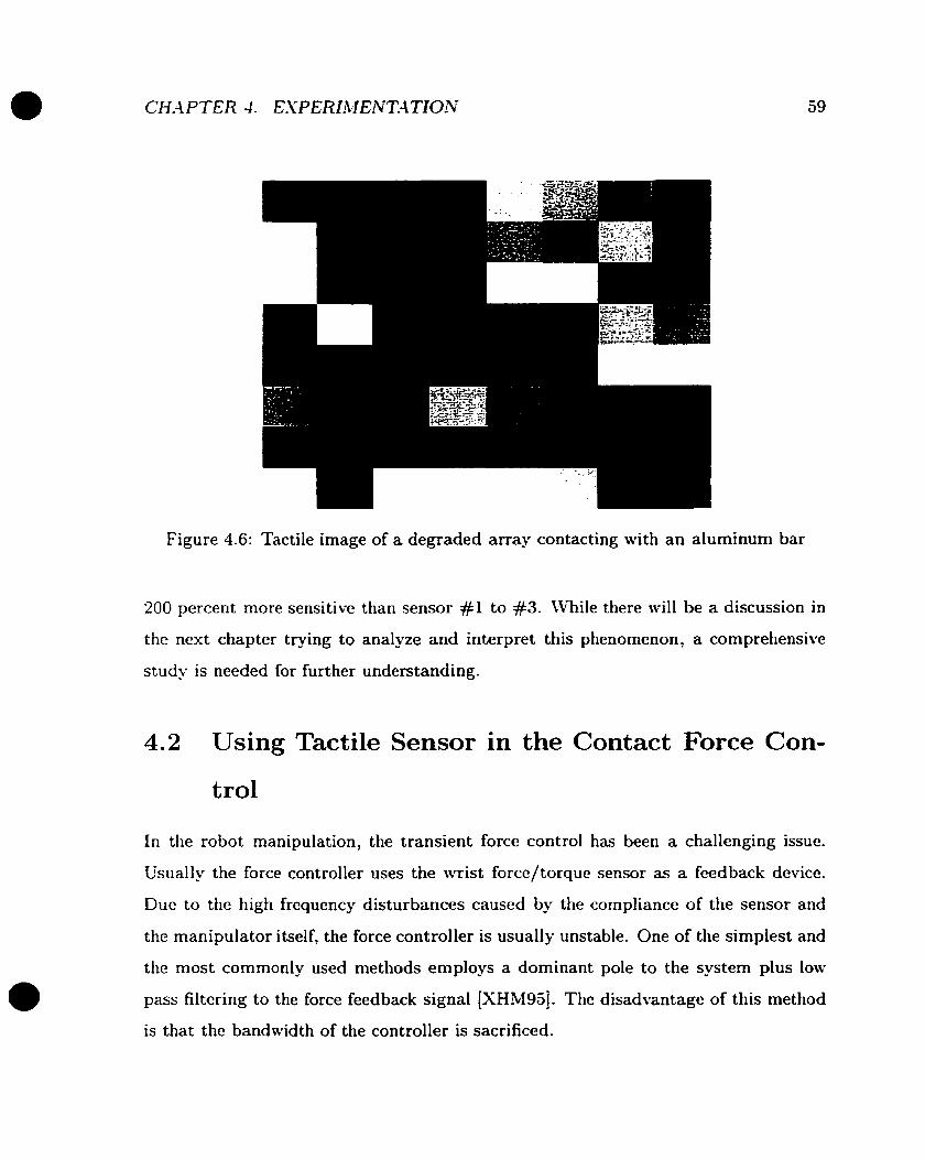
Figure 4.6: Tactile image of a degraded array contacting with an aluminum bar
200 percent more sensitive than sensor #l to #3. While there will be a discussion in
the nest chapter trying to analyze and interpret this phenornenon, a comprehensive
study is needed for further understanding.
4.2 Using Tactile Sensor in the Contact Force Con-
trol
In the robot manipulation, the transient force control has been a challenging issue.
Usually the force controller uses the wrist force/torque sensor as a feedback device.
Due to the high frequency disturbances caused by the cornpliance of the sensor and
the manipulator itself, the force controller is usually unstable. One of the simplest and
the most commonly used methods employs a dominant pole to the system plus low
pass filtering to the force feedback signal [XHM95]. The disadvantage of this method
is that the bandwidth of the controller is sacrificed.
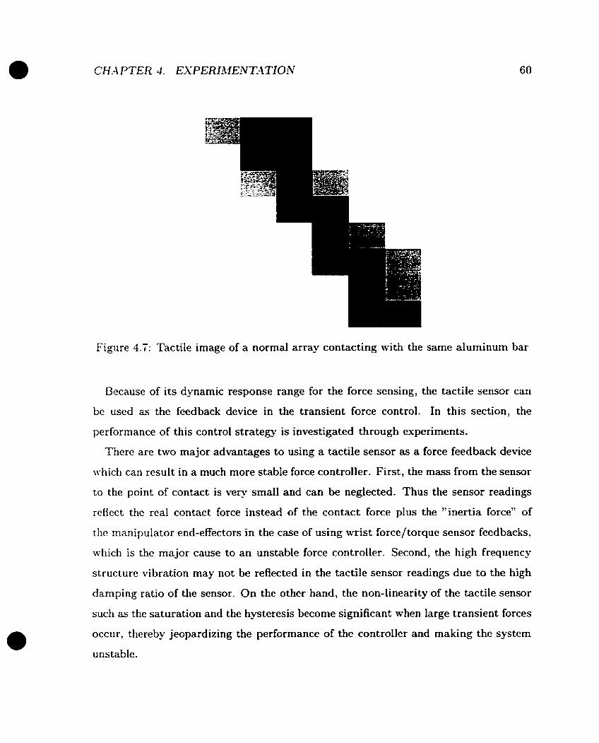
Figure 4.7: Tactile image of a normal array contacting with the same aluminum bar
Because of its dynamic response range for the force sensing, the tactile sensor can
be used as the feedback device in the transient force control. In this section, the
performance of this control strategy is investigated through esperirnents.
There are two major advantages to using a tactile sensor as a force feedback device
which can result in a much more stable force controller. First, the mass frorn the sensor
to the point of contact is very small and can be neglected- Thus the sensor readings
reflect the real contact force instead of the contact force plus the "inertia force" of
the manipulator end-effectors in the case of using wrist force/torque sensor feedbacks,
which is the major cause to an unstable force controller. Second, the high frequency
structure vibration may not be reflected in the tactile sensor readings due to the high
damping ratio of the sensor. On the other hand, the non-linearity of the tactile sensor
such as the saturation and the hysteresis become significant when large transient forces
occur, thereby jeopardizing the performance of the controller and making the system
unstable.

Force Control Using Y N Lnadccll or Tactile * Scnsor Feedback
b
1
Figure 4.8: Block diagram of a loadcell or tactile sensor based transient force controller
In the experiment, the actuator command is pre-filtered by a first order low-pass
digital filter with 1OOH.z cutoff frequency while no low pass filter is applied to either the
loadcell or the tactile sensor. The force set point is 3.ON and the threshold for position-
force switching is 0.1N. Before the tactile sensor/load ce11 reading exceeds O.IN, the
probe keeps moving towards the tactile array through a position PD control using
LVDT/LVVT as feed back devices. -4s soon as the tactile sensor/load ce11 reading
reaches O.IN, the control immediately switches to force PD control using either of
the tactile sensor or the loadcell as the feedback device. This strategy is depicted in
Figure 4.8. Figure 4.9 and Figure 4.10 show the results of the transient force control
using loadcell and tactile sensor readings as feedbacks, respectively. The controller
using the tactile sensor works well, while the controller using the loadcell is not stable.
-4 good force controller needs accurate force measurement for feedback. The reason
tactile based force control performs better is simply because the tactile sensor gcnerally
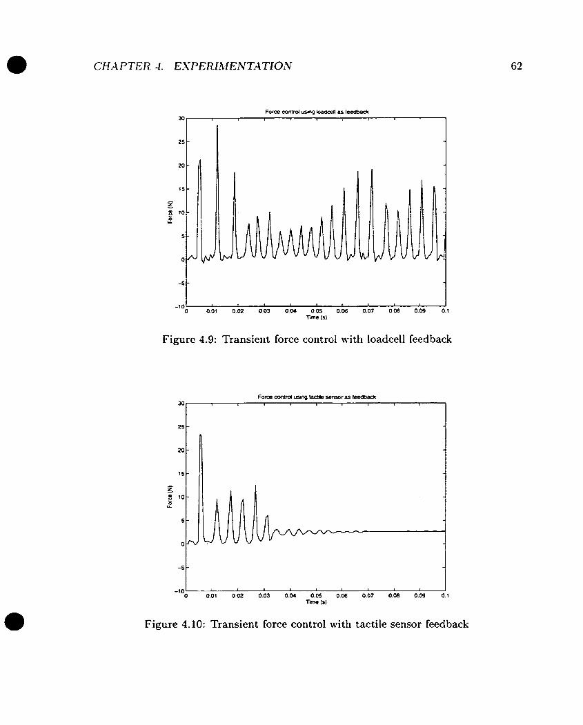
Figure 4.9: Transient force control with loadcell feedback
Figure 4.10: Transient force control with tactile sensor feedback

records actual contact force more precisely. However. this ma? not be always true.
Based on the fact that the tactile sensor gets saturated and larger hysteresis appears
in the response when large transient force occurs, the tactile sensor could be doing a
worse job. So why not switch back to the loadcell under such situation? Based on this
argument, a modified PD controller employing both the loadcell and the tactile sensor
is tested. The controiler simply switches to the loadcell from the tactile sensor when
the reading from the tactile sensor is beyond a threshold and switches back as soon as
the reading \iras below it. In this case, the threshold is 5.ON, a turning point bepnd
which the tactile sensor starts to be saturated. Figure 4.11 demonstrates the control
law graphically and Figure 4.12 shows the results. It is obvious that this strategy
results in a better controller compared to Figure 4.9 and Figure 4.10.
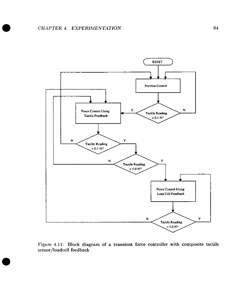
1 Position Control I
< Tactile Reading > Force Conirol Using A N - Tactile Feedback
Force Control Using Load Cell Fcedbwk
Figure 4.11: Block diagram of a transient force controller with composite tactile sensor/loadceli feedback
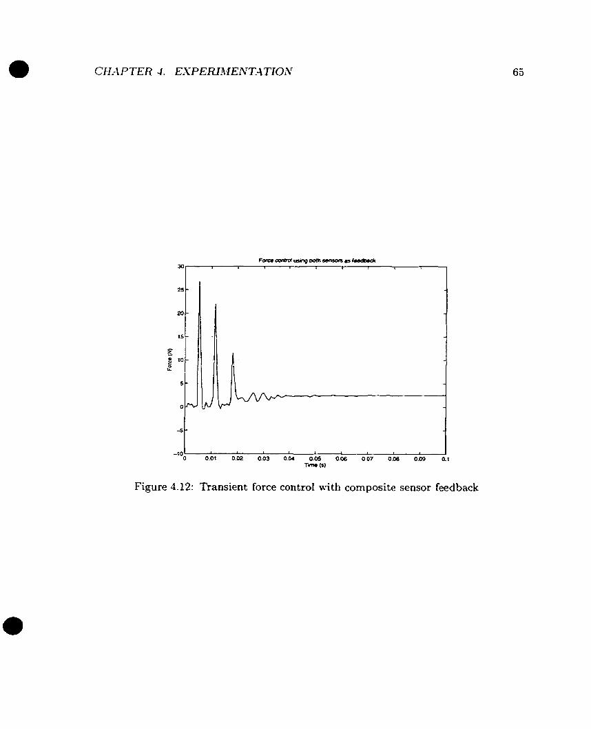
CH-4 PTE R 4. EXP EFUMENT-4 TION
Figure 4.12: Transient force control with composite sensor feedback
Chapter 5
Discussion and Conclusion
5.1 The Conductive Silicone S hielding
Tlie idea of using conductive silicone in the top layer of a tactile array is to forrn a
shielding which reduces the electrical-magnetic interference. Because of the limited
tools and highly complicated nature of the materials being used. an ideal shielding
l a y r is never guaranteed. It is interesting to observe that the use of this material
does not always have the positive impact on the sensor performance. In our case,
espcrimental results also show the Ehl interference does not cause noticeable damage
to the sensor reading. This is possibly due to the relativelÿ large size of individual
tactile cell.
The "conductive silicone" is actually the pure silicone which is a non-conductive
compound mised mith tiny silver (R-2937) or silwr-aluminum alloy balls (LSR-9923)
wliose maximum diameter is around 50pm. The density of these metal balls is high
enough to let them have constant contact to each other. The material therefore has a
very good conductivity but obviously it is not homogeneous compared to metal.
Figure 2.1 illustrates the basic electrical mode1 of a tactile sensor. Things get a little
more complicated when the sensor is covered by a conductive silicone layer. There
arc two additional parasitic capacitors introduced in this case and theÿ will possibly
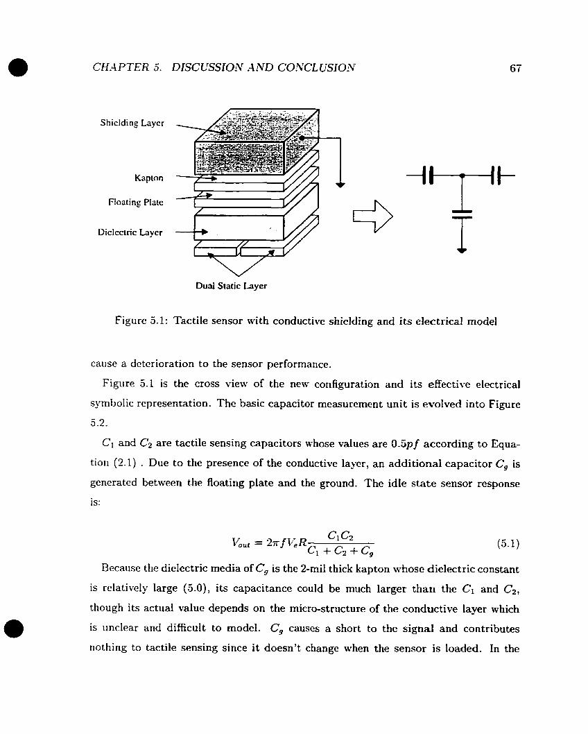
S hicldi ng Layer
Kapton
Floating Plate
Diclectric Layer
Dual Static Layer
Figure 5.1: Tactile sensor ivith conductive shielding and its electrical mode1
cause a deterioration to the sensor performance.
Figure 5.1 is the cross view of the new configuration and its effective electrical
symbolic representation. The basic capacitor measurement unit is evolved into Figure
5 -2.
Cl and Cz are tactile sensing capacitors whose values are 0.5~ f according to Equa-
tion (2.1) . Due to the presence of the conductive layer, an additional capacitor Cg is
generated between the floating plate and the ground. The idle state sensor responsc
is:
Because the dielectric media of Cg is the 2-mil thick kapton whose dielectric constant
is relatively large (5.0), its capacitance could be much larger than the Ci and C2,
though its actual value depends on the micro-structure of the conductive layer which
is unclear and difficult to modei. C, causes a short to the signal and contributes
nothing to tactile sensing since it doesn't change when the sensor is loaded. In the

CH-4 P TER 5. DISCUSSION A4rVD CONCL USION
Tactile Scnsor R r---- 1 I
V U U l
Figure 5.2: ivlodified tactile sensing unit
worst case, Cg can be as larger as:
which results in an attenuated sensor response of:
While in the the best case where Cg does not exist, the sensor response is:
Comparing (5.4) with (5.3), the sensor could be 5.7 times more sensitive using non-
conductive silicone. This may esplain the result from the experiment. On the other
hand, from the fact that a sensor with a non-conductive top layer is twvo hundred
percent more sensitive, Cg can be calculated:
More serious problems occur when the conductivity of this shielding is degraded
which is observed over a period of time after the rubber has cued. Under such a
situation the grounding of this shielding layer could become very poor and even broken

Two coupled cells
Ground ring 1 \
Dcgnded shielding
One not well shielded cell : '/?--%--'L-
- - - - - - - - - - - - - shielded cell
I Cell onc I l
I
Figure 5.3: Illustration of a tacti!e array with degraded shiclding and its electrical mode1
(this could happen due to the limited contact between shielding layer and the PCB
ground ring). In this case, the shielding layer becornes a large floating conductive layer
or a set of isolated conductive islands floating on the top of kapton as shown in Figure
5.3.
The shielding becomes an "antenna" and is closely coupled with the floating plates
through C,, the second parasitic capacitor. The "antenna" introduces huge noise and
dramatically changes the entire electrical characteristic of the sensor when the sensor
makes a contact with a metal object, which is often remotely grounded through a very
large loop. Notice that C, is distributed al1 over the sensor arra- the noise introduced
from one contact location may cause a false sensor response at a distant location.
Viewing from the output of the entire array, this appears as a radical cross talk as
observed from the experiment (Figure 4.6).
In the case of non-conductive silicone top layer, this "antenna effect" is highly
reduced because this out-most layer is 20 times thicker (40rnils vs. 2mils) therefore

the coupling between the floating plate and the metal object can be reduced. This
may esplain why the performance of the sensor with the conductive silicone shielding
gets worse after being used for a certain period of time. It is unclear how the silicone
loscs its conductivity. It could be caused by the changes of chernical characteristics of
the material or caused by fatigue of the rubber.
Based on above arguments and esperimental results, it is clear that a poor shielding
is worse than no shielding at all. Since the conductive silicone is not a homogeneous
conductive material, it is not guaranteed that the entire piece is always well grounded.
The "antenna effect" exists more or less depending on its condition. The interna1
micro structure of this material is unclear and complicated therefore is very difficult
to model. While the fully understanding of this phenomena is a further research topic,
the sensor with normal non-conductive silicone top layer works estremely well and is
adopted in the current design.
5.2 Future Work
The work covered in this thesis is the research and development of a rubber based tact-
ile scnsing array and al1 the essential supporting hardware and software. Combining
an infrared proximity sensing array, the InteIIigent Gripper System is composed. A
tactile sensor based force control scheme is also investigated. Based on these achieve-
ments, more research is able to be conducted.
5.2.1 Application of the Intelligent Gripper System
The robot manipulation based on both tactile sensors and prosimity sensors remains
an very interesting topic in the future. A typical experiment could have a robot, for
esample, a Sarcos Dextrous Slave Arrn equipped with the Intelligent Gripper to track,
grâsp and manipulate an object in a planned manner. The moving object is plastic or
fragile which only sustains small forces.
The esperimcnt has three phases. Each of them should be studied separately.
During the tracking phase, tlie gripper position/velocity controller uses infrared
prosimity sensors to retain the location and orientation of the object' though this
information is normally not very accurate due to the nature of the prosimity sensor.
At the end of the tracking phase, the gripper is ready to perform grasping at a planned
location and orientation.
During the grasping phase, both sensors are used. The controller uses the prosimity
sensor as the feedback before the contact occurs and the gripper is under the position
control. Meanwhile, the controller monitors the tactile sensor response to detect the
occurrence of the contact. As soon as the contact occurs, the control switches into the
transient force control immediately using feedbacks from the tactile or tactile/loadcell
pair. The controller will normally switch between the position control and the force
control a few times until the grasping is stabilized.
The third phase is thc manipulation which actually involves actirities described in
tlie tracking and grasping phases. The gripper may release and re-grasp the object on
a constant basis. The management and utilization of tactile and prosimity information
is critical. Further study may be focused on optimized grasping in which case, the
object surface information observed by tactile sensors is used to develop an optimized
surface to surface grasping.
5.2.2 Sensor Improvements
Ii7hile tlie current tactile scnsor meets the spccifications and fulfills the requirement
during riormal operations, there are a number of issues to bc addressed which may
furthcr improve the performance.
First is the spatial resolution. The spacing of the current design is 2.54mm. Though
a lmm spatial resolution is achieved by analyzing the sensor response from the neigh-
borhood cells 4.2, this scheme is only valid for large object localization. The sensor
array is not able to identify or to locate objects smaller than 2.54 mm in an accurate
CH-4 PTER 5. DISCUSSION -4 ND CONCL USION - t 3
manner. The tactile resolution of the human finger is about 1 mm [PJ8l]. In order to
achieve this performance, the density of the tactile sensor matris over the array has
to be increased considerately.
However: this approach reduces the physical dimension of an individual sensor ce11
by the order of two and results in a proportionally smaller sensing capacitance. Not
only is it more difficult to rneasure a smaller tactile capacitor but also, in this case, the
noise introduced by environment interference will be more visible- One approach is to
find new material with larger dielectric constant for dielectric layer to compensate the
loss of sensing capacitance. Nevertheless, to improve the resolution of a tactile sensor
in this category is a big challenge to researchers.
The second issue is the non-linearity in the sensor response, the hysteresis in par-
ticiilar. It is suspectcd that the kapton is the major cause of this problem. While
the silicon used in the dielectric layer has an excellent elasticity, the kapton which
hosts the floating plate recovers from deformation v e l slowly. A large contact force
may even bend it permanently The use of thinner and more cornpliant kapton wi11 be
a good solution though the kapton thinner than 2 mil (which is used in the current
design) has not been seen in the market. The best solution is to get rid of this kapton
completely. But this approach raises the question of how to implant the floating plates.
The third issue is about the conductive silicone shielding layer. A bad conductive
top layer will jeopardize the sensor performance dramatically. Though in the current
design, a shielding layer is not a necessity, it may be mandatory if the size of an
individual tactile ce11 is reduced since the signal/noise ratio will be worse. To find
an escellent compound of conductive silicon is a challenging job but will definitely
contribute a great deal to the tactile sensing research.

5.3 Conclusion
In this thesis. the Intelligent Gripper Systern as a product prototype is presented.
The system integrates a rubber based tactile sensing array and an infrared prosim-
itj- sensing system with the complete supporting and interfacing electronics into one
standalone and portable package. Though the system is specifically designed for the
Sarcos Destrous h m , it is ready to be adapted or recast to other robot end effectors
due to its modular and portable approach.
The Intelligent Gripper System is composed with three functional modules. The
tactile sensing subsystem module integrates a tactile array and its supporting elec-
tronics. The 8 x 8 tactile sensor array is based on the capacitance rneasurement and
constructed with multiple rubber layers. To achieve goals of robustness, manufactur-
ability and iow cost, the tactel spacing is designed as 2.54mm. -4s a result, at least
two tactile sensor arrays with very good working order have been built. In order to
reduce the nonlinearity in the sensor response and estend the life of sensors. a float-
ing conductive layer configuration instead of conventional strips has been succcssfully
adopted. To reduce the noise in sensor response, the supporting electronics including
pre-amplification and multiplesing is completely localized in the form of a solid-state
part.
The infrared proximity subsystem is based on the LED/photo-transistor pair, the
dcvice developed by Petryk and Buehler [PB961 though the associated electronics is
spccially designed to support four sensing channels. The sensor head including the
LEDs and photo-transistors are integrated into the gripper fingcr along with the tactile
sensing subsystem. To simplify the design one LED excitation is shared bu two scnsing
channels. Al1 the associated electronics is packed into one small printed circuit board
which can be easily installed anywhere close to the finger tip.
The interface module performs a role as an electronic and data hub for two sensor
subsystems and the master controller. The module is based on an MC68HCll rnicro-
processor (MCU) which makes the whole system "intelligent". The analog signal from

110th sensors is converted to digital signal by an 8-bit on-chip -A/D converter before
bcing further directed to the master controller through a universal bi-directiorial par-
allel port. An esternal on-board analog to digital converter offering 14-bit resolution
is also available and can be used for analysis. There are two additional digital to ana-
log converters which serve as gain and offset schedulers to eliminate the static offset
in tlic sensor response and to normalize the signals beforc converting them into di-
gital signals- The interface module also accepts commands from the master controller
through the parallel port to configure and to trigger the sensing operation. The MCU
also allocates the necessary hardware resources to perform a possible low level digital
data processing in the future applications. Since al1 small signal processing circuits
are strictly localized or constrained into the two subsystems, there are only digital
signals and large analog signais exchanged among three modules, the systein has an
optimized Electrical-Magnetic Compatibility (EMC).
As a by-product, a Windoivs based development and evaluation system for the
lK68HCll based embedded system is devcloped. ft is a powerful tool for similar
systern research and development and lias potential commercial value.
There are three parts of experiments conducted in the thesis. First is the evaluation
and the verification of al1 the electronics and programs running in the h.1CU. It insures
that al1 the issues raised in the design stage are addressed. The overail electronic
dcsign is proved successful.
Tlic second part of the experiment is to evaluate and characterize the tactile sensor
in terms of electrical properties such as noise level and masimum sampling rate, and
mechanical properties inciuding static, dynamic and spatial perforniances. Under cur-
rent design, the tactile sensor ce11 can be sampled as fast as 1h'H.z (13Hz for the entire
array) with 1mV noise in I V range. The sensor has a small 7 perccrit non-linearity
witii a composite lmm spatial resolution, although the tactel spacing is 2.54mm. Thc
sensor can be modeled as a second order system with 220Hz bandwidth.
The third part of the esperiment is a preliminary investigation on the use of the

tactile sensor in the transient force control. It has been shown that the contact force
is better coritrolled through less-local joint force/torque sensors. Furthermore, a com-
posi te tactile-joint force/torque sensor based force cont rol st rategy has been proposed.
I t yields the best performance, as the dynamic range could be divided between them.
These results further support the argument of the utility of tactile sensors.
Finally. the effectiveness of the conductive shielding layer on the top of the tactile
array and how it affects the sensor performance have been addressed. Though it is
more on the theoretical basis, this will certainly help to further improve the sensor
performance in the future.
Appendix A
Materials used for Tactile Array
1. R-2186. Non-conductive silicone used for dielectric iayer and top layer. Nusil
Silicone Technology Inc. (1050 Cindy Lane, Carpinteria, C-493013).
3. R-2937. Silver based conductive silicone used for shielding Iayer. Nusil Silicone
Technology Inc. (1050 Cindy Lane, Carpinteria, CA93013).
3. LSR-9923: Silver-aluminum based conductive silicone used for shielding layer.
Nusil Silicone Technology Inc. (1050 Cindy Lane, Carpinteria, C.493013).
4. Tactile base PCB. 60 mil - 85 mil, available from local PCB manufacturer,
5 . Kapton layer. 2 mil, available in local PCB Manufacturer.

Appendix B
Schematics

Figure B.1: Interface module: MCU: address decoding and SC1
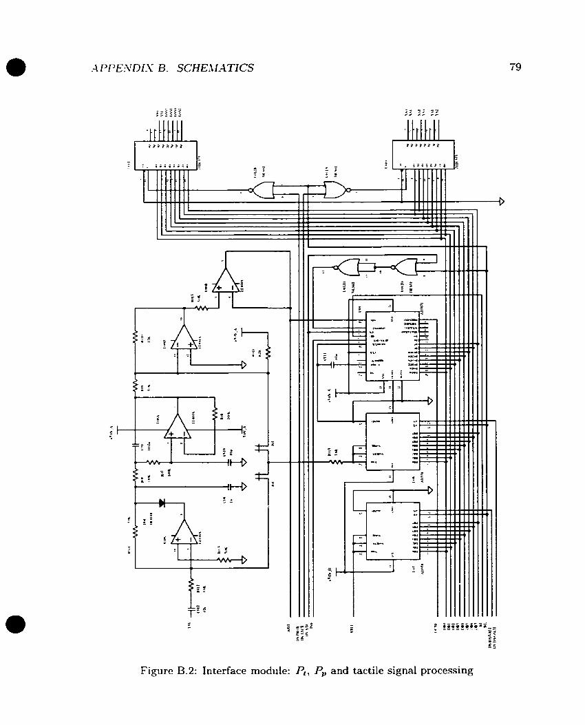
Figure B.2: Interface module: Pt, P, and tactile signal processing
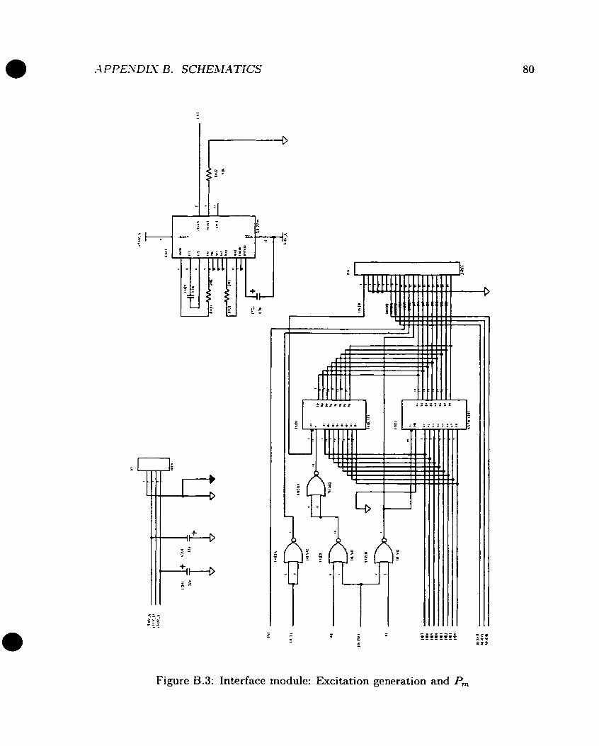
Figure B.3: Interface module: Excitation generation and Pm
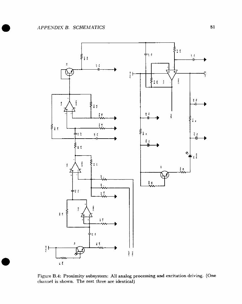
Figure B.4: Proximity subsystem: Al1 analog processing and excitation driring. (One channel is shown. The rest three are identical)
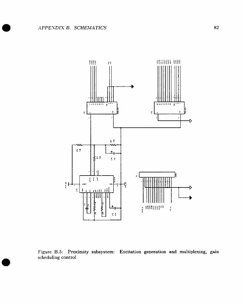
Figure B.5: Proximity subsystem: Excitation generation and multiplexing, gain scheduling control

Appendix C
Lists of the MC68HCll Program
Due to the limit of the space, lists of the MC68HCll Program are available upon
request.

Bibliography
Kazuo Asakawa. Robot assembly of precision parts using tactile sensors.
ildvanced Robotics, v. 1 n. 159-69, 1986.
Alan D. Berger and Pradeep K. Khosla. Using tactile data for real-time
feedback. International Journal of Robotics Research, v. 10: n. 2:88-102:
4 1991.
R. A. Boie. Capacitive impedance readout tactile image sensor. In Proc.
1st IEEE Computer Society Int. Conf. on Robotics, pages 370-379, March
1984.
P. Dario. Tactile sensing for robots: present and future. The Robotics
Review 1, pages 133-146, 1989.
R. S. Fearing and T. O. Binford. Using a cylindrical tactile sensor for
determining curvature. IEEE Trans. Robotics and Automation, v. 72306-
817, 1991.
-4. S. Fiorillo, P. Dario, and hl. Bergamasco. Sensorized robot gripper.
Robotics, v. 4, n. 1:49-55, Mar 1988.
R. S. Fearing. Tactile sensing mechanisms. Int. J. Robotics Research, v.
9, n. 3:3-23, 1990.
Steven J. Gordon and William T. Townsend. Integration of tactile-force
and joint-torque information in a whok-arm manipulator. In IEEE Int
84

BIBLIOG R-4PHY 85
Conf Rob Autom, volume VI (of 3), pages 464-469, Intelligent Autom Sÿst
Inc. Cambridge, M A , US-\. 1989. IEEE, IEEE Service Center, Pisçataway,
SJ, USA.
[HC92] R. D. Hoive and M. R. Cutkosk. Touch sensing for robotic manipulation
and recognition. The Robotics Review 2, pages 55-112, 2992.
[Hi1821 1 . D i l l i s Active touch sensing. International .Journal of Robotics
Research, v. 1, n. 2:33-44, Summer, 1982.
[.JhlBP88] S. C. Jacobsen, I. D. McCammon, K. B. Biggers, and R. P. Phillips.
Design of tactile sensing systems for dextrous manipulators. IEEE Control
Systems Magazine, v. 8 , n. 1:3-13, 1988.
D. Johnston, P. Zhang, and J.hL Hollerbach. -4n full tactile sensing suite
for dextrous robot bands and use in contact force control. In IEEE inter-
national Conference for Robotic.~ and Automation, pages 1286-1291, -4pril
1996.
Sukhan Lee. Distributed optical proximity sensor system: Heseye. In Pro-
ceedzngs - IEEE international Con ference on Ro botics and Automation,
volume (IEEE cat n 92CH3140-2). v. 2, pages 1567-1572, Jet Propulsion
Lab, California Inst of Technol, Pasadena, CA, US-4, 1992. IEEE, IEEE
Service Center, Piscataway, N J , US-4-
Sukhan Lee and Hernsoo Hahn. Recognition and localization of 3-d natural
quadric objects based on active sensing. In Proceedings - IEEE Intema-
tional Conference on Robotics and Automation, volume (91CH2969-4).
v. 1, pages 156-161, Jet Propulsion Lab, California Inst of Technol, Pas-
adena, CA, USA, 1991. IEEE, IEEE Service Center, Piscataway, N J , USA.
1. D. McCammon. Tactile Sensing for Dextrous Robot Hands. PhD thesis,
Dept. Mechanical Engineering, University of Utah, 1990.
1. D. McCammon and S. C. Jacobsen. Tactile sensing and control for the
Utah/MIT hand. Springer-Vcrlag, NY, 1990.
J. L. Wovak and J. T. Feddema. -4 capacitance-based prosimity sensor
for whole arm obstacle avoidance. In Proceedings - IEEE International
Conference on Robotics and Automation. volume ( I E E E cat n 92CH314O-
1). T. 2? pages 1307-1314. IEEE. IEEE Service Center. Piscataway, KJ?
USA, 1992.
G. Petryk and M. Buehler. Dynamic object localization via a prosimity
sensor network. In IEEE/SICE/RSJ Int. Conf. Multisensor Fusion and
Integration for Intelligent Systems, pages 337-34 1 , Dec 1996.
J. R. Phillips and K.O. Johnson. Tactile spatial resolution. ii. rieural
represe~itation of bars, edges, and gratings in monkey primary afferents.
J . Neurophysiol., v. 46: llW-I203, 1981.
[PhIYTSâ] Emil LI. Petriu, William S. blchlath, Stephen S.K. Yeung: and Xiculaie
Trif. Active tactile perception of object surface geometric profiles. IEEEE
Transactions on Instrumentation & Measurement, v. 41, n. 1, Feb 1992.
[RIi89] Rocky R. Reston and Edward S. Kolesar. Pressure-sensitive field-effect
transistor sensor array fabricated from a piezoelectric polyvinylidene flu-
oride film. In Proceedings of the Annual Conference on Engineering in
Medicine and Biology, volume v. 11: pt. 3, pages 918-919! US Air Force
Inst of Technol, Dep of Electr Si Comput Eng, Dayton, OH, USA, 1989.
Alliance for Engineering in Medicine & Biology, Bethesda, MD, US.4.
Available from IEEE Service Cent (cat n 89CH2770-6), Piscataway, NJ,
US.4.
IV. 1. Rafla and F. L. Mcrat. Vision-taction integration for surface repres-
entation. In IEEE International Conference on Systems Engineering, Aug
1990.
Dominiek Reynaerts and Hendrik Van Brusse. T w d n g e r e d full envelope
desterous manipulation. In Proceedings - IEEE International Conference
on Robotics and Automation, volume v. 2: pages 436-441, Katholieke Univ
Leuven, Heverlee, Belg, 1993. IEEE, IEEE Service Center, Piscatawap
NJ, USA.
Hiroyuki Shinoda and Shigeru Ando. Ultrasonic emission tactile sensor
for contact localization and characterizatioii. In IEEE International Con-
ference on Robotics and Automation, pages 2536-2543, Univ of Tokyo.
Tokyo: Jpn. 1994. IEEE Service Center, Piscataway, NJ, US-4. pt 3.
D. M. Siegel, 1. Garabieta, and J. M. Hollerbach. An i~itegrated tactile
and thermal sensor. In lEEE International Conference for Robotics and
Automation, pages 1286-1291, April 1986.
Jeffrey S. Schoenwald and Jim F. Martin. Fiber optic tactile sensor for ro-
bot grippers. Technical report, Technical Paper - Society of Manufacturing
Engineers, Rockwell Ent Science Cent, Thousand Oaks, C-4, USA.
T. Speeter. -4 tactile scnsing system for robotic manipulation. Interna-
tional Journal of Robotics Research, v. 9, n. 6:25-36, December 1990.
Jean-Pierre Uldry and R. -4ndrew Russell. Developing conductivc elast-
omers for applications in robotic tactile sensing. Aduanced Robotics, v. 6 ,
n. 2:233-271, 1992.
John M. Vranish. Magnetoinductive Skin for Robots. IFS Pub1 Ltd, K e m p
ston, Engl, & Springer-Verlag, Heidelberg, West Ger & Yew York, NY,
US.4, NBS, USA.

(SHIrl95I Y. Su: J . kl. Hollerbach, and D. bla. -4 nonlinear PD controller for force
and contact transient control. IEEE Control Systen, v. 15: n. 1:l5-21,
1995.