integrating design and construction through virtual
TRANSCRIPT

INTEGRATING DESIGN AND CONSTRUCTION THROUGH VIRTUAL
PROTOTYPING
Ting Huang1, Heng Li1, C W Kong1, H L Guo1, Andrew Baldwin2 , Neo Chan1 and Johnny Wong1
1 Department of Building and Real Estate, The Hong Kong Polytechnic University
2 Faculty of Construction and Land Use, The Hong Kong Polytechnic University
Abstract
Construction Virtual Prototyping (CVP) is the use of integrated product, process and
resource models of construction projects to support the construction planning in virtual
environment. This paper describes an integrated framework and process for efficient
application of CVP to support project teams on construction planning. It includes specific
examples of models and objectives as well as detailed suggestions on how to implement
CVP in practice.
Keywords: Construction planning; 3D modeling; Process simulation; Virtual prototyping
1. Introduction
A comparison of productivity data between manufacturing and construction industries is
interesting and revealing. For example, Figure 1 indicates that within last 40 years, the
manufacturing industry has made approximately 10% incremental annual improvements
while the construction industry continuously declined.
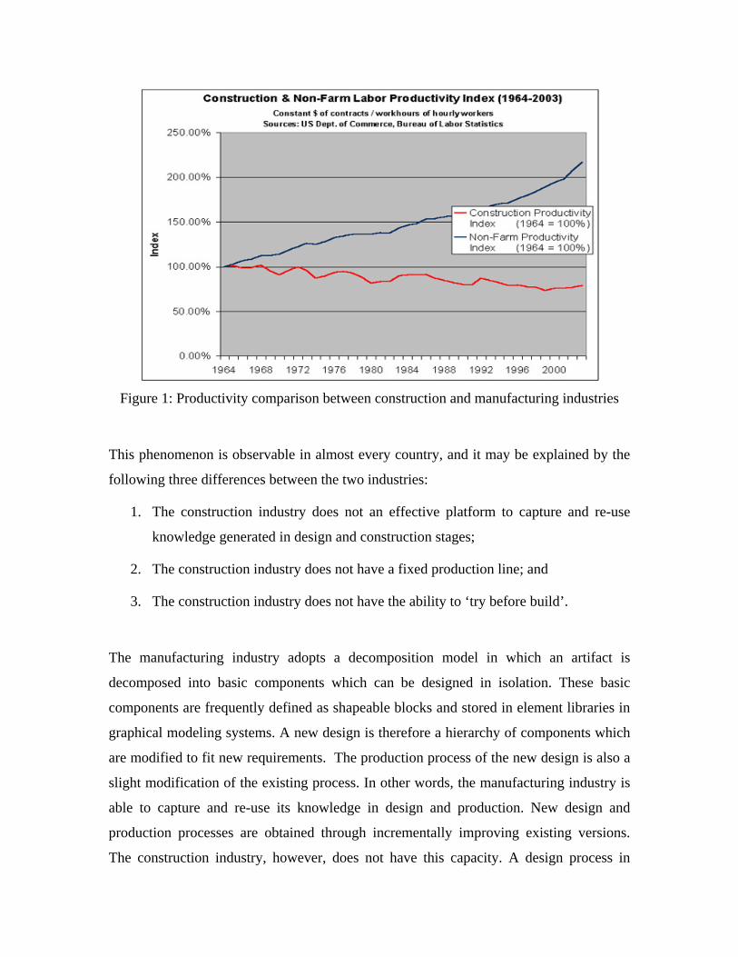
Figure 1: Productivity comparison between construction and manufacturing industries
This phenomenon is observable in almost every country, and it may be explained by the
following three differences between the two industries:
1. The construction industry does not an effective platform to capture and re-use
knowledge generated in design and construction stages;
2. The construction industry does not have a fixed production line; and
3. The construction industry does not have the ability to ‘try before build’.
The manufacturing industry adopts a decomposition model in which an artifact is
decomposed into basic components which can be designed in isolation. These basic
components are frequently defined as shapeable blocks and stored in element libraries in
graphical modeling systems. A new design is therefore a hierarchy of components which
are modified to fit new requirements. The production process of the new design is also a
slight modification of the existing process. In other words, the manufacturing industry is
able to capture and re-use its knowledge in design and production. New design and
production processes are obtained through incrementally improving existing versions.
The construction industry, however, does not have this capacity. A design process in

construction typically starts from a blank sheet of paper, and this goes through the entire
construction process where new contract, new teams and processes are formed. When the
project is completed, little knowledge is captured and retained.
In addition, the manufacturing industry has a fixed production line where the productivity
is dominated by the speed of machinery; whereas the construction industry does not have
a production line and project participants have to exercise personal judgments to find the
best way to complete their tasks.
Moreover, the lack of ability to ‘try before build’ turns construction to a very risky
business. A construction project is by and large an experimental process guided by design
and planning information which is particularly full of incompleteness and mistakes. As a
result, rework has been ubiquitous and time and cost overruns are common.
The above three issues are the bottleneck that hinders the incremental improvement of the
construction industry. In order to remove the bottleneck, research team at The Hong
Kong Polytechnic University started a research project in 2004 to develop the virtual
prototyping technology. Virtual prototyping (VP) is a computer-aided design process
concerned with the construction of digital product models (‘virtual prototypes’) and
realistic graphical simulations that address the broad issues of physical layout,
operational concept, functional specifications, and dynamics analysis under various
operating environments [1-3]. Dedicated VP technology has been extensively and
successfully applied to the automobile and aerospace fields [4]. However, the
development and application of VP technology in the construction industry (i.e.
construction process simulation) has been limited. This is probably because that each
construction project is unique in terms of the site conditions, requirements, and
constraints. Sarshar et al. [5] identified three major industrial barriers to uptake VP
technology, including cultural and risk issues related to information sharing,
fragmentation of business interests and the lack of piloting on real construction projects.

3D/4D models support planners by relating building components from a 3D CAD system
to construction activities from a project planning system, using a graphical interface. The
construction process can then be simulated by executing the process modeler built in the
VP system and the user can visually check how the process proceeds. 4D CAD systems
can be used for construction analysis and communication [6]. Hartmann and Fischer [7]
developed an integrated process of how project teams can use 3D/4D models efficiently
to support the knowledge communication and generation needed during the
constructability review on construction projects. Although 3D/4D model can help the
planners to analyze the design, find out the collision and discover missing or conversed
sequence, the 4D process developed by Hartmann and Fischer emphasized the knowledge
transfer to engineer or none-construction managers during the construction planning. This
application is quite useful because the efficient communication is the key factor of
successful construction. But at most of time, verifying the appropriate construction
method and making sure the feasible construction schedule are the first issues concerned
by general contractor before transferring the planning knowledge. The experience from
our research told us that the process of supporting the construction planning with the VP
technology should assist planners to verify their planning as well as transfer their
planning knowledge.
This paper presents a case study of applying virtual prototyping technology to a real life
construction project. It identifies the need of virtual prototyping technology and presents
a new profession which is named process modeler. The role of the process modeler in the
project procurement process is discussed. Skill set for the process modeler is defined. The
paper concludes that the virtual prototyping technology can remove the bottleneck of the
construction industry.
2. Process Modeler as a new profession

The Construction Virtual Prototyping Laboratory (CVPL) at The Hong Kong Polytechnic
University has applied VP technology to several real construction projects in Hong Kong.
VP technology enables contractors to “construct the building many times” in the
computer. All sorts of scenarios can be previewed and potential problems identified in
advance in this simulation process. The simulation process performs such tasks as the
production, transportation, handling and assembly of different construction components,
including all the associated operational processes. All the variables affecting the
construction processes, such as site layout, plant locations, rate of machinery operation,
quantities of resources, etc., can be considered in order to evaluate the feasibility of the
proposed construction methods and sequences, and to explore possible solutions and
improvements to the methodology prior to actual work beginning.
However, the VP technology is unfamiliar to contractors. Contractors expected but
doubted the VP application on their projects in the beginning. General contractors and
their planners often have little idea about how construction VP can help them. Some
regard VP technology as only animation tools that represent their planning ideas more
clearly. Although the new technology is useful to construction planning and project
management, the misunderstanding of planners can be a major impediment for the
adoption of the VP technology in the industry. In order to demonstrate the usefulness of
the technology, researchers of the Construction Virtual Prototyping Lab at The Hong
Kong Polytechnic University have worked very closely with contractors of several real
life projects in Hong Kong. In fact, for each project, a researcher has been seconded to
the site office to assist the planning and project monitoring process.
Due to the fact that neither the design team nor the construction team has the capacity to
apply the virtual prototyping technology, researchers of the Construction Virtual
Prototyping Lab act as the process modeler to connect the design and construction teams.
The process modeler accepts the BIM model from the designer, and decomposes it into
formats required by the main contractor, subcontractors and consultants. At the same time,
the process modeler integrates information provided by the construction team into the

BIM model to create a virtual prototyping of construction processes. Information from
the construction team typically includes temporary designs, preliminary planning and
costing information. Through an iterative process, the process modeler enables the
construction team to conduct ‘what-if’ analyses of different construction methods in the
virtual prototyping environment, until a satisfactory method is obtained.
From our experience of conducting virtual prototyping studies of over 10 real life
construction projects, we consider that the process modeler needs skills that can be
categorized under three headings:
Technical skill. This requires the process modeler to understand construction processes,
to have a strong hands-on knowledge of virtual prototyping software systems,
Human skill. The ability to work with other people of the construction team. The process
modeler needs to be self-aware, understanding and sensitive to the feeling and thoughts
of others to maintain a healthy interpersonal relationships with the rest of construction
team.
Conceptual skill. The process modeler needs to understand the schematic representations
for process, product and resource models. These schematic models provide a theoretical
underpinning for construction virtual prototyping technology.
These three categories of skill need to be presented in different proportion. In a very
empirical sense, the technical skill dominates and should be within the range of 40%; the
human skill 35% and the conceptual skill 25%.

3. Traditional construction planning process
Construction project planning has been considered as a critical process in the early
project phases that determines the successful implementation and delivery of project.
During this stage, project planners need to develop main construction strategies, to
establish construction path and assembly sequences, to arrange construction methods and
resources required for the execution of work packages, and even to write daily work
instructions for field crews [8-10]. The left part of Figure 2 is a diagram representing the
process of construction planning. The planning process requires the transformation of
information into analysis, decisions and actions. The general process of the VP models
application is showed as the right part of Figure 2. Within this process, VP models
support the knowledge generation and transformation at each of the planning step.
Analyze design information
Static 3D product models
Propose construction method
Static 3D resource models
Verify construction method
Dynamic process simulation
Submit and deliver construction method
Visualized schedule and work instruction
Virtual Prototyping
Fig. 2. Underpinning the construction planning with VP
In the first step of the application process, static 3D product models are built to help the
project team analyze and communicate design information. The design errors can be
detected in 3D product models. The preparation of 3D product models also includes the

modeling of site environment that can be used to study the site layout and review the
constructability.
The second step is to build static 3D resource models including construction equipment
and temporary works. Planners will propose some potential construction methods which
may be suitable for the uniqueness of project design and construction site. Using the 3D
resource models with the previous product models, the optional construction methods can
be expressed in the virtual platform.
The third step is to simulate the construction process. The dynamic process simulation is
a series of activities, each of which can have a defined duration, linked with construction
components and resources (Figure 3). First, the abstract construction methods can be
visualized by assigning the 3D product and resource models. Then the visualized
methods can be tested and verified by integrating temporal and spatial considerations.

Fig. 3. Integrated product, process and resource models of the construction project
In the final step of the construction planning process, the project team needs to submit or
deliver the developed construction method to other participants such as project client,
subcontractors and field crews. The visualized schedule and work instruction can help the
construction planning effectively communicated and implemented.
The CVPL researcher’s experience on the several real construction projects shows that
the above described integrated process effectively supported the construction planning of
project teams. However, due to the pressure of planning time, the timeliness of VP
models is quite important for the efficiency and effectiveness of construction project
management. VP models which require information can not be built after the information

is complete. Therefore, the content of VP models varied to satisfy with the different
stages of construction planning. The construction planning process usually is broken
down into two stages: macro and micro planning processes [8]. Although the main
process of the planning is the same, the tasks of the planning are different. During the
preconstruction stage, the macro planning process involves reviewing the design for
constructability improvement, selecting major construction methods and resources, and
planning site layout. During the construction stage, the micro planning process develops
detail schedules to instruct the day-to-day operation. The above integrated process in
Figure 2 can meet the different planning tasks in the preconstruction and construction
stages by adjusting the content of VP models. In the following part, we will present a
case study of applying virtual prototyping technology to a real life construction project
and describe the content of VP models for different stages in this project. The detail
approach for 3D modeling and process simulation are skipped over in this paper and can
be found in Huang et al [11].
4. Case study
Island East project
Island East project consists of the development of a 70-story office building located in a
central business area of Hong Kong. The structural type is core wall with eight mega
columns in the typical floor. One outrigger is designed for strengthening the structural
system between the core wall and columns from the 34th floor to 40th floor. And floor
area reduced from 55th floor to the roof by incline the column. The research works in this
project include planning the typical floor construction, and resolve the constructability
problems during the outrigger installation (Figure. 4).

Fig. 4. The research works for Island East Project
In this project, the duration is of paramount important, because the delay could result in
potential claim from the client. In order to win the project in the tendering stage, general
contractor has committed a pressing schedule to client. Therefore, the four-day typical
floor cycle and the outrigger installation will be big challenges for the general contactors.
The VP technology is applied to support the contractor to plan the detail schedule,
generate shop drawings and instruct the construction work. The following subsection will
describe the product modeling process, resource modeling process, detail method
simulation process, and work instruction process in the construction stage.
1st floor
33th floor
Typical floor construction
70th floor
Outrigger area construction
Roof area construction
Typical floor construction 55th floor
40th floor

3D product model supported analyzing design process
Before propose the construction method, the planners will analyze the project design and
site environment. So the 3D Models of product model and site model can provide a
virtual experiment platform to review the design, select the construction equipment and
method, plan the site layout, and verify the safety issues, et al.
4.1 Construction components modeling To select the construction equipment and method, the project team will review the design
drawings and breaks down the building or facility into major components such as
columns, beams, slabs, and walls. The 3D component models, which attributes such as
length, volume and weight can be directly measured, can assist planners to study how
these components will be built and controlled on site.
3D product model is also good at analyze the spatial relationship of the construction
components. In this work, the reinforcement embedded in the outrigger are difficult to
design and fix because the steel members’ shape are irregular and working space is strait
in the climb form. The contractor needed to make sure that the reinforcement detailing
was extremely well coordinated with steel members so that it could ensure the on-time
installation of outrigger. The process modeler used detailed, parametric 3D models to
support the design of the reinforcement embedded in the outrigger. The 3D model
prototype was used for design coordination of this complicated area as well as detail
drawing production and prefabrication. Over a two week period, the rebar detailer built
the virtual 3D prototype model with the aid of our process modeler on the computer
(Figure 5.a).
4.2 Site modeling In Hong Kong, the construction site is quite confined. Site investigation usually occurs at
the beginning of the project and includes major issues such as site access and planning
[8]. Planners will study the location of unloading area and the entrance of vehicle when
the construction material is coming. In addition, the hazardous areas of lifting the
materials need to be considered in planning.

In this project, the weight of some outrigger steel members is close to the capacity of
tower crane. The path of the lifting and hazardous area is built in 3D site model. And also
the vehicle for outrigger might conflict with the concrete mixer truck. The paths of these
vehicles are built in the site model for the planners (Figure 5.b).
The static 3D product model and site model can assist the planners to analyze the site
constraint, identify the potential problems, and plan some possible construction methods.
These modeling efforts also reduced the number of review sessions to a minimum and
ensured that the detailed design was well coordinated and maximized prefabrication
opportunities and field productivity and safety.
3D resource model supported proposing construction method process
4.3 Construction equipment modeling Construction methods are determined by the building products and the construction
equipment. After review the design and site survey information, the planners will find
some possible construction equipment which is thought to be suitable to the construction
product and site. Construction equipment’s installation, dismantlement, site layout,
loading limit, and space requirement while moving are sorts of concerns in the planning.
So, the next step of VP modeling is the construction equipment modeling.
In this project, the climb form is fixed on the core wall by support pins and support
beams, which are inserted into the pockets reserved on the wall. Planners will study the
height of every climb form lifting. The location of the pockets is one of the
considerations. The 3D models of support pins and support beams are added to the
original rough climb form model (Figure 5.c). Once the planners adjust the height of
climb form lifting, the location of the pocketed can showed if it is clashed with the
reinforcement of beams.
4.4 Temporary works modeling The temporary works usually cost a large part in contract. Failure in planning appropriate
temporary works affects safety, quality, and productivity adversely [12]. To build the 3D
temporary works model is benefit to the contractor because the design error and the

collision with construction components will be checked. In addition, the safety provided
by the temporary works can be reviewed by safety consultants before the construction.
In this work, the wall formwork designed for the typical floor did not fit these non-typical
floors for outrigger. Temporary formworks will be used to make up the unfit area. These
areas are irregular changed due to the variable beam size and the location of the original
wall formworks. The 3D temporary formwork was built to content the unfit areas (Figure
5.d). The quantity and dimension of the temporary formworks needed can be generated
from the model and provided to planners to study.
(a)
(c) (d)
(b)
Fig. 5. 3D product and resource models of Island East project
Construction method simulation and verification
4.5 Construction method visualization In a traditional planning process, planners need to construct a 3D mental model of the
construction project by mentally integrating 2D drawings, CPM based schedules and

other information. This is largely an experience based process, thus more experienced
planners often construct more comprehensive mental models and therefore generate
better construction plans. The VP technology overcomes this weakness as it provides a
platform to visually simulate construction process including all 3D models of the design,
the site environment and the resources to be used in the project. The simulation can not
only provide the same level of understanding to all project participants, but only facilitate
effective communication among them. More importantly, the simulation model provides
an in-expensive and safe platform for project participants to evaluate different
construction methods and identify possible risks and problems.
To develop the VP simulation model, the following information is needed.
• What construction equipment is used for specific component and how does it
operate?
• How are the construction components installed and what are the installation
sequence?
• What kind of temporary works are needed and where to install them?
With the above information and 3D models of the design and site environment, the
construction project can be digitally represented and its processes digitally simulated and
evaluated.
4.6 Method verification process Virtual prototyping technology can help planners to study every step of the construction
activities by running through the whole construction process in the simulation system. If
problems are found, planners need to propose remedial actions and then re-run the
simulation process to verify if the proposed remedial actions are workable. This trial and
error process continues until the whole construction process is evaluated. Thus, with the
use of VP technology, most construction risks and problems can be identified and solved
before the commencement of the project.

In this project, table formworks were selected for the slab construction and the climb
form for the core wall construction. Planners must ensure the safe and smooth operation
of the four-day floor cycle by using the detailed, step-by-step, simulation of the
construction process. During this simulation, many problems were identified and
corrective measures were taken. Figure 6 shows some examples of identified problems
such as the collision between the table formwork and column working platform and
conflict between tower crane and climb form. After going through the whole project, the
contractor has gained sufficient confidence of the selected construction method.
Fig. 6. Identified problems during the method verification process
Visualized schedule and work instruction
4.7 Visualization of construction process as a communication tool between project participants
Once the simulation is completed, it can used for many purposes. For example, as the
simulation visually presents the construction process, it can be easily understood by the
client. A complex schedule is hard to be understood and implemented by many
subcontractors and field crews. At the construction stage, the learning period for field
crews is often required. The effective work instruction will shorten this learning period.
The pictures extracted from the VP model were used to give subcontractors and field
crews a visualized work instruction. The project has been completed on time within

budget. After the completion, both the client and contractor admitted that it would not be
possible without the use of virtual prototyping technology.
4.8 Working space visualization In the detail planning process, planners need to optimize the time and resource use based
on the master program. The detail method can be developed to provide work instruction
to crews. The working space is an important factor affecting the efficiency of
construction work. Planners must develop the detail method and schedule according to
the working space. However, it is difficult for planners to image the working space in the
mental model. In addition, once the construction joint or the location of the construction
equipment is changed, the working space will be different. The VP technology can help
planners to visualize the working space and to examine the available working.
As an example, Figure 7 indicates how the VP technology is used to examine the
availability of working space.
Fig. 7. Visualized work instruction versus the real installation

5. Conclusions
The development and application of the Virtual Prototyping (VP) technology in the
construction industry is still relatively new. This paper describes an integrated framework
and process for general contractors to apply the VP technology. The process described in
this paper can assist planners to verify their plans so that construction risks can
eliminated before the commencement of the project.
The benefits of using VP can be summarized as follows:
• The creation, analysis and optimization of construction schedules
• Effective constructability analysis
• Elimination of construction risks through digital mockup of processes
• Clearer understanding of project scope and better work instruction from main
contractor to subcontractors
• Effective communication between the client and contractors
• Effective management of design changes and,
• Better capture and re-use of knowledge
The application of VP trims down the managerialism but introduces a new profession,
process modeler, into the industry, the skill set required by the process modeler has been
identified.
In addition, the use of VP may enable the industry to remove the three bottleneck issues.
As VP technology requires designers to modularize design into BIM (Building
Information Management) models which are 3D models with information for
performance evaluation of the models, this encourages standardization and prefabrication.
Prefabrication indirectly introduces a production line into the construction industry. VP
can realistically simulate construction processes and effectively capture design and

construction knowledge which can be re-used in future projects. In addition, VP provides
the platform for practitioners to ‘try before build’ the project.
Acknowledgements Funding for data collection and analysis was supplied through the Research Grants
Council of Hong Kong through allocation from the Competitive Earmarked Research
Grant for 2005/06 under Grant Number PolyU5103/05E. The research has also been
supported by another Competitive Earmarked Research Grant for 2005/06 under Grant
Number PolyU 5209/05E.
References [1] Q. Shen, J. Gausemeier, J. Bauch, R. Radkowski, A cooperative virtual prototyping system for
mechatronic solution elements based assembly, Advanced Engineering Informatics 19 (2005) 169–177.
[2] W. Xiang, S.C. Fok, G. Thimm, Agent-based composable simulation for virtual prototyping of fluid power system, Computers in Industry 54 (2004) 237–251.
[3] M.J. Pratt, Virtual prototyping and product models in mechanical engineering, Virtual Prototyping—Virtual Environments and the Product Design Process, Chapman and Hall, London, 1995, pp. 113–128.
[4] S.H. Choi, A.M.M. Chan, A virtual prototyping system for rapid product development, Computer-Aided Design 36 (2004) 401–412.
[5] M. Sarshar, P. Christiansson, J. Winter, Towards virtual prototyping in the construction industry: the case study of the DIVERCITY project, Proceedings of the World IT Conference for Design and Construction, 18–24 Feb 2004, Langkawi, Malaysia, 2004, pp. 581–588.
[6] B. de Vries, M.J. Harink, Generation of a construction planning from a 3D CAD model, Automation in Construction 16 (2007) 13 – 18.
[7] T. Hartmann, M. Fischer, Supporting the constructability review with 3D/4D models, Building Research & Information 35(1) (2007) 70–80.
[8] A.F. Waly, W.Y. Thabet, A virtual construction environment for preconstruction planning, Automation in Construction 12 (2002) 139–154.
[9] B. Koo, M. Fischer, Feasibility study of 4D CAD in commercial construction, Journal of Construction Engineering and Management 126(4) (2000) 251–260.
[10] A. Jaafari, K.K. Manivong, M. Chaaya, Interactive system for teaching construction management, Journal of Construction Engineering and Management 127 (2001) 66–75.
[11] T. Huang, C.W. Kong, H.L. Guo, A. Baldwin, H. Li, A virtual prototyping system for simulating construction processes, Automation in Construction (2006), doi:10.1016/j.autcon.2006.09.007
[12] A. Chini, G. Genauer, Technical guidance available to designers of temporary structures, American Society of Civil Engineers Fifteenth Structures Congress, Portland, Oregon, 1997.