integrated analysis of afterburning in a gas turbine ...integrated analysis of afterburning in a gas...
TRANSCRIPT

Integrated analysis of afterburning in a gas turbine cogenerative power
plant on gaseous fuel
BARBU ENE, IONESCU SILVIU, VILAG VALERIU, VILCU CONSTANTIN, POPESCU JENI,
IONESCU ADINA, PETCU ROMULUS, PRISECARU TUDOR, POP ELENA, TOMA TATIANA
Cogeneration Department
COMOTI Romanian Research and Development Institute for Gas Turbines
220D Iuliu Maniu Ave. 061126 Bucharest
ROMANIA
[email protected] http://www.comoti.ro
Abstract: - The afterburning installation allows the increase in the cogenerative group’s flexibility according to
the requirements of the technologic process and increases the steam quantity delivered by the heat recovery
steam generator. The requirements concerning the development of high performance equipments with low
environment impact and high flexibility have increased lately. Therefore a complex analysis is needed for
obtaining the necessary data for designing the afterburning installation. The paper presents the researches
carried out at Suplacu de Barcau gas turbine cogenerative power plant on the afterburning installation as well as
the phase of bench experimentations for an intimate research of the processes and for the elimination of
disturbing factors in the plant. The researches at the cogenerative plant were carried out in different operating
conditions, in terms of stack emissions, noise, external superficial temperature profile and electric energy
quality.
Key-Words: - Afterburning, Gas turbine, Cogeneration, Noise, Infrared, Emissions, Flue gases
1 Introduction Through a more efficient utilization of the fuel the
cogeneration leads on the one hand to decrease in
costs and increase in product competitiveness and
on the other hand to a significant decrease of
emissions. The development of gas turbines in terms
of performances as well as life time, exploitation
cost and reliability made these installations
preferable for cogenerative processes, the reduced
investment costs leading to 3 – 4 years dumping and
15 – 20 years total life cycle. The improvement of
the overall efficiency of a cogenerative power plant
depends on the use of waste heat from the turbo-
engine and is accomplished by using a heat recovery
steam generator. The performances of the heat
recovery steam generator depend on the turbo-
engine operating conditions making the steam
parameters difficult to control. It is possible to apply
supplementary fuel combustion (afterburning) for
increasing the steam flow, compared to a heat
recovery steam generator as the combustion turbine
process consumes a small fraction of oxygen. The
afterburning is commonly used in aviation to
increase the thrust of supersonic aircraft engines, its
introduction in cogenerative applications leading to
increased overall efficiency of the cogenerative
group. The trend in the field of heat recovery steam
generator and afterburning installations are related
to the development in gas turbines. The increase in
the temperature of the turbo-engine exhaust
temperature requires new materials that withstand
operating regimes in terms of appropriate norms
pollutants. Turbo-engine performance is affected by
ambient temperature and load, which affect the heat
recovery steam generator operation. The burned
gases flow is turbulent and unevenly distributed in
the outlet cross section of the turbo-engine. In some
areas at the heat recovery steam generator inlet
backflow may occur. A uniform distribution of flow
is an important factor participating to afterburning
good functioning and ensuring the heat recovery
steam generator performance. The gases discharged
from the turbo-engine already have a high
temperature (about 550 °C) leading to high burner
thermal efficiency [1]. Network type burners are
designed to evenly distribute the heat in the heat
recovery steam generator cross section which
requires a careful oxygen supply in order to avoid
high emissions of pollutants and flame length
variation. Designing the turbine-afterburning-heat
recovery steam generator system must take into
account these variables to ensure the steam
parameters required by the technological process.
The major manufacturers of afterburning equipment
aim the accomplishment of high performance
installations with low exhaust emissions. As a result
WSEAS TRANSACTIONS on ENVIRONMENT and DEVELOPMENT
Barbu Ene, Ionescu Silviu, Vilag Valeriu, Vilcu Constantin, Popescu Jeni, Ionescu Adina, Petcu Romulus, Prisecaru Tudor, Pop Elena, Toma Tatiana
ISSN: 1790-5079 405 Issue 6, Volume 6, June 2010

of these trends researches have been carried out at
2xST 18 – Suplacu de Barcau Cogenerative Plant
(superheated steam boiler) concerning the
afterburning installation under contracts 22-
108/2008 and 21-056/2007 (Partnerships in priority
areas), financed by Ministry of Education, Research
and Youth [1,3]. The researches aimed to analyze
the processes in the afterburning installation at 2xST
18 Cogenerative Plant at different operational
regimes in order to improve the performance. The
research examined the afterburning as part of the
cogenerative group in terms of stack emissions,
noise, surface temperature profile and power
quality. Based on these measurements and a
numerical model [1] the combustion modules have
been redesigned and experiments have been started
to establish the performance of the new burner
geometry.
2 Afterburning at 2xST 18 - Suplacu
de Barcau Cogenerative Plant.
Integrated analysis system for
afterburning 2xST 18 – Suplacu de Barcau Cogenerative Plant
(Fig. 1), beneficiary PETROM Group OMV, is
located in Romania, Bihor county, 75 km from
Oradea. 2xST 18 – Suplacu de Barcau
Cogenerative Plant simultaneously produces
electricity and heat and is the first product of its
kind equipped with gas turbines, designed and built
entirely in Romania by Romanian specialists. The
Plant was fully put into operation in 2004, operating
within the oil scaffolding of Suplacu de Barcau.
Fig. 1 View of 2xST 18 Suplacu de Barcau
Cogenerative Plant
2xST 18 Suplacu de Barcau Cogenerative Plant
consists of two groups (Fig. 2) that can operate
simultaneously or separately. Each group is
composed mainly of one ST 18 gas turbine, one heat
recovery steam generator, one afterburning
installation and associated installations. The heat
recovery steam generator corresponding to each
cogenerative group is ignitubular type, with two gas
lines – one horizontal, the other vertical, consisting
of: afterburning chamber without water cooling;
superheater to ensure steam at 300 °C; pressure
body to provide saturated steam; saver assembly –
water preheater to ensure water parameters needed
for pressure body feeding [2]. The exhaust gases
produced by the turbo-engine pass through the
burner of the afterburning installation where they
reach the corresponding temperature. The gases
follow the horizontal line of the heat recovery steam
generator (superheater – pressure body) and then the
vertical one (saver – water preheater – stack). 2xST
18 Suplacu de Barcau Cogenerative Plant works in
automatic mode, the operating personnel receiving
information at the control panel by optical signal
boxes or acoustic signals on the occurrence of
irregularities on supervised parameters or on
production of damage. Certain parameters
(pressures, temperatures, flow etc.) of the
equipments from the Plant may be stored or
displayed through a data acquisition system. The
electricity is used in the scaffolding to drive the
reduction gears of the wells, compressors, pumps as
well as for the lightning, and the thermal energy
(steam) is injected into the deposit, as required by
the technologic process of oil extraction and /or
other requirements of the scaffolding (buildings or
technological pipelines heating).
Fig. 2 Machines layout at 2xST 18 Suplacu de
Barcau Cogenerative Plant
WSEAS TRANSACTIONS on ENVIRONMENT and DEVELOPMENT
Barbu Ene, Ionescu Silviu, Vilag Valeriu, Vilcu Constantin, Popescu Jeni, Ionescu Adina, Petcu Romulus, Prisecaru Tudor, Pop Elena, Toma Tatiana
ISSN: 1790-5079 406 Issue 6, Volume 6, June 2010
2.1 The afterburning of 2xST 18 - Suplacu de
Barcau Cogenerative Plant The afterburning installation (burner with
automation) of 2xST 18 – Suplacu de Barcau Plant
was delivered by Saacke Company
(www.saacke.com - Germany) with the
characteristics calculation in Table 1 [2, 3]. The
burner (Fig. 3) delivered by Saacke (produced by
Eclipse - Netherlands) is “FlueFire” type, dedicated
to this type of application. It can be placed directly
into the combustion gases between the turbo-engine
and heat recovery steam generator, but can also
function on fresh air. The burner has 21 firing
modules placed on three natural gas supply ramps
and two modules for flame propagation. In the
“FlueFire” burner the gases from the turbo-engine
are introduced through an adaptation section,
ensuring an intimate mixture with the fuel through
vortex generation of the gases in the combustion
fuel jets. This leads to cooling and stabilizing the
front burner combustion, allowing high
temperatures downstream, at a low content of
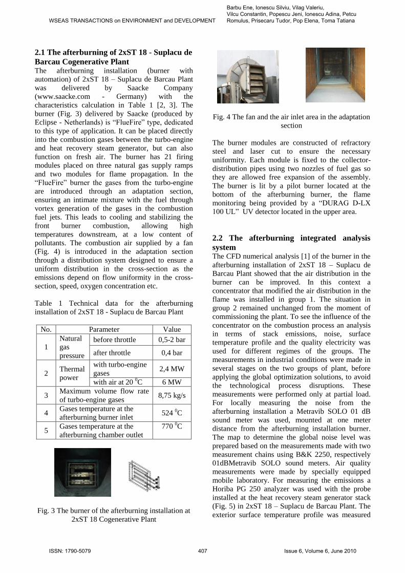
pollutants. The combustion air supplied by a fan
(Fig. 4) is introduced in the adaptation section
through a distribution system designed to ensure a
uniform distribution in the cross-section as the
emissions depend on flow uniformity in the cross-
section, speed, oxygen concentration etc.
Table 1 Technical data for the afterburning
installation of 2xST 18 - Suplacu de Barcau Plant
No. Parameter Value
1
Natural
gas
pressure
before throttle 0,5-2 bar
after throttle 0,4 bar
2 Thermal
power
with turbo-engine gases
2,4 MW
with air at 20 0C 6 MW
3 Maximum volume flow rate
of turbo-engine gases 8,75 kg/s
4 Gases temperature at the
afterburning burner inlet 524
0C
5 Gases temperature at the
afterburning chamber outlet
770 0C
Fig. 3 The burner of the afterburning installation at
2xST 18 Cogenerative Plant
Fig. 4 The fan and the air inlet area in the adaptation
section
The burner modules are constructed of refractory
steel and laser cut to ensure the necessary
uniformity. Each module is fixed to the collector-
distribution pipes using two nozzles of fuel gas so
they are allowed free expansion of the assembly.
The burner is lit by a pilot burner located at the
bottom of the afterburning burner, the flame
monitoring being provided by a “DURAG D-LX
100 UL” UV detector located in the upper area.
2.2 The afterburning integrated analysis
system The CFD numerical analysis [1] of the burner in the
afterburning installation of 2xST 18 – Suplacu de
Barcau Plant showed that the air distribution in the
burner can be improved. In this context a
concentrator that modified the air distribution in the
flame was installed in group 1. The situation in
group 2 remained unchanged from the moment of
commissioning the plant. To see the influence of the
concentrator on the combustion process an analysis
in terms of stack emissions, noise, surface
temperature profile and the quality electricity was
used for different regimes of the groups. The
measurements in industrial conditions were made in
several stages on the two groups of plant, before
applying the global optimization solutions, to avoid
the technological process disruptions. These
measurements were performed only at partial load.
For locally measuring the noise from the
afterburning installation a Metravib SOLO 01 dB
sound meter was used, mounted at one meter
distance from the afterburning installation burner.
The map to determine the global noise level was
prepared based on the measurements made with two
measurement chains using B&K 2250, respectively
01dBMetravib SOLO sound meters. Air quality
measurements were made by specially equipped
mobile laboratory. For measuring the emissions a
Horiba PG 250 analyzer was used with the probe
installed at the heat recovery steam generator stack
(Fig. 5) in 2xST 18 – Suplacu de Barcau Plant. The
exterior surface temperature profile was measured
WSEAS TRANSACTIONS on ENVIRONMENT and DEVELOPMENT
Barbu Ene, Ionescu Silviu, Vilag Valeriu, Vilcu Constantin, Popescu Jeni, Ionescu Adina, Petcu Romulus, Prisecaru Tudor, Pop Elena, Toma Tatiana
ISSN: 1790-5079 407 Issue 6, Volume 6, June 2010

using a Fluke infrared camera, type Ti45FT,
targeting being done at the top of the burner of the
afterburning installation (Fig. 6). The process
parameters for the turbo-engine, heat recovery
steam generator and afterburning were read either
on display (Fig. 7) or locally. Data correlation was
made in terms of pollutants, noise, exterior surface
temperature profile and power quality by reporting
the recording time. Electro-energetic measurements
were made in the electric generator cell (Fig. 8) by
means of measuring transformers. The electro-
energetic measurements were made using both fixed
devices mounted in panels (ammeters, voltmeters,
active and reactive energy meters) and portable
equipment (power network analyzer and power
quality type CA 8332B).
Fig. 5 Mobile laboratory and Horiba PG 250
analyzer with the probe installed at the heat
recovery steam generator stack
Fig. 6 Scope of endorsement by the Ti45FT type
Fluke camera and sound level meter
Fig. 7 Command and control room at 2xST 18 Plant
with data acquisition system
Fig. 8 Power distribution station (left) and CA
8332B network analyzer (right)
3. Experimental data and numerical
modelling The data obtained so far consist of experiments at
2xST 18 Cogenerative Plant, numerical simulations
in CFD environment and bench experiments on gas
and air.
3.1 Data obtained at experimentations in
2xST 18 Cogenerative Plant In a first stage the noise map for the second group of
the power plant (without air concentrator) have been
performed), to have comparative data for recording
state of local noise at the afterburning system
burner. The noise map was first realized by adding
the sound power of 12 measured points close to the
turbo-engines, and then correction of sound
directivity and correction for wall reflections have
been achieved. Also based on measurements with
sound level meter in 50 points outside and inside
around the cogeneration plant, the noise map
presented in Fig. 9 has been verified and corrected
by changing the acoustic parameters of the software
related to reflections and transmissibility trough
walls. Note that in the area of the afterburning
installation, burner noise level is in the 80 - 85 dB
range, and the strong noise curves deformation and
large values are met in the turbo-engines hall area.
WSEAS TRANSACTIONS on ENVIRONMENT and DEVELOPMENT
Barbu Ene, Ionescu Silviu, Vilag Valeriu, Vilcu Constantin, Popescu Jeni, Ionescu Adina, Petcu Romulus, Prisecaru Tudor, Pop Elena, Toma Tatiana
ISSN: 1790-5079 408 Issue 6, Volume 6, June 2010

In the second stage were performed measurements
on group 1 (with air concentrator) in terms of NOx
emissions, noise and superficial external
temperature profile to the heat recovery steam
generator operation of the afterburning working on
fresh air. During this time group 2 worked in
cogeneration regime (turbo-engine + afterburning +
heat recovery steam generator). There was obtained
the set of experimental data corresponding to five
operating regimes, defined by the temperature of the
flue gases at the end of the afterburning chamber
(tca): 500 0C, 552
0C, 604
0C, 645
0C, 700
0C.
Variation of NOx emissions and noise, locally
recorded in the afterburning installation burner,
depending on the temperature of the flue gases,
recorded with a thermocouple at the end of
afterburning chamber, is given in Fig. 10.
Fig. 9 Noise Map of 2xST 18 Cogeneration Power
Plant - Suplacu de Barcau, group 2 in operation and
group 1 stopped
0
20
40
60
80
500 550 600 650 700
tca [0C]NOx [ppm] Noise [dB]
Fig. 10 NOx and noise variation depending on gas
temperature at the end of afterburning chamber -
group 1 (afterburning + heat recovery steam
generator)
From Fig. 10 we can see that the increase of flue gas
temperature leads to NOx emissions increase, while
the noise is almost constant, at approx. 81 dB. In
terms of the superficial external temperature profile,
concerned according to Fig. 6, there is a growing of
region occupied by isothermal line with
temperatures above 200 0C (Fig. 11, left), as the
temperature at the end of afterburning chamber
grow from 500 0C to 645
0C. In the third stage
we’ve performed noise, emissions and superficial
external temperature profile measurements at the
group 2 (without air concentrator). The cogenerative
group was functioning without afterburner (turbo-
engine + heat recovery steam generator) and with
afterburner (turbo-engine + afterburning + heat
recovery steam generator). There were obtained two
experimental sets of data. One of the experimental
data set corresponds to three different working
regimes of the turbo-engine + heat recovery steam
generator configuration, and is defined by the flue
gases temperature measured at the end of the
afterburning chamber (tca), respectively: 423 0C, 437
0C, 475
0C. The other experimental data set
corresponds to turbo-engine + afterburner + heat
recovery steam generator configuration and has
been conducted at followings flue gases
temperatures measured at the end of the
afterburning chamber (tca): 536 0C, 569
0C, 605
0C,
645 0C. In Fig. 11 and 12 (right side) are given the
isotherms configuration and the histogram for turbo-
engine + afterburning + heat recovery steam
generator arrangement. Working at fresh air rating,
more than 645 0C, the region occupied by the
isotherms is reduced, but is much larger than the
isotherms corresponding to the group 2 (without air
concentrator – Fig. 11 right side) working in
cogenerative regime (turbo-engine + afterburning +
heat recovery steam generator) or turbo-engine +
heat recovery steam generator (without afterburner).
These observations are confirmed by the histograms
in Fig. 12.
Fig. 11 Isotherms configuration at groups 1 (left)
and 2 (right), through infrared registration at tca =
645 0C;
left – group 1 (with concentrator): heat recovery
steam generator + fresh air afterburning;
right – group 2 (without concentrator): turbo-engine
+ afterburning + heat recovery steam generator
WSEAS TRANSACTIONS on ENVIRONMENT and DEVELOPMENT
Barbu Ene, Ionescu Silviu, Vilag Valeriu, Vilcu Constantin, Popescu Jeni, Ionescu Adina, Petcu Romulus, Prisecaru Tudor, Pop Elena, Toma Tatiana
ISSN: 1790-5079 409 Issue 6, Volume 6, June 2010

Fig. 12 Histograms at groups 1 (left) and 2 (right),
through infrared registration at tca = 645 0C;
left – group 1 (with concentrator): heat recovery
steam generator + fresh air afterburning;
right – group 2 (without concentrator): turbo-engine
+ afterburning + heat recovery steam generator
The area occupied by the isotherms in the central
region (to the board of the afterburning chamber) to
group 2 (without concentrator), for these operating
regimes, is reduced as the gas temperature at the
afterburning chamber outlet (tca increases). Unlike
this situation, as noted above, the functioning of
group 1 (with concentrator) the area occupied by the
isotherms increases with the increase in gas
temperature at the afterburning chamber outlet (tca).
For group 2 (without concentrator, turbo-engine +
afterburning + heat recovery version), the NOx
variation and the noise locally recorded to the
burner of the afterburning installation (Fig. 6) with
the burned gases temperature is given in Fig. 13.
Fig. 13 shows that the NOx emissions increase with
the increase in temperature, but the values are
higher than the ones in Fig. 10 (group 1 with
concentrator). It is possible that the pollutant level is
caused by the irregularities introduced by the gas
turbine as well as by the lack of the concentrator.
The noise also increases with the increase in
temperature. The local noise measurements made
near the burner in the second and third stage
confirm the values in Fig. 9. The electro-energetic
measurements are presented in Fig. 14 - 19, tracking
the power variation at the electric generator
terminals and the distortion coefficients variation
from fundamental (THD), for current and voltage,
depending on gas temperature at the afterburning
chamber outlet. In the turbo-engine + heat recovery
steam generator version the variation in the heat
recovery steam generator load is made by variation
the turbo-engine parameters. This leads to an
increase in power at the electric generator terminals
along with the increase in temperature at the
afterburning chamber outlet (Fig. 14). In the turbo-
engine + afterburning + heat recovery steam
generator version the variation of the heat recovery
steam generator load is made by variating the
afterburning parameters leading to a quasi-constant
power at the electric generator terminals
(approximately 1220 kW) while the temperature at
the afterburning chamber outlet increases (Fig. 15).
80
100
120
140
160
180
520 570 620
tca [0C]NOx [ppm] Noise [dB]
Fig. 13 NOx and noise variation depending on
temperature at the afterburning chamber outlet –
group 2 (turbo-engine + afterburning + heat
recovery steam generator)
In the turbo-engine + heat recovery steam generator
version the value of the distortion coefficients from
the fundamental (THD), for current and voltage,
decrease with the increase in the temperature at the
afterburning chamber outlet (Fig. 16 - 17). This
decrease is more acute for the current (Fig. 16)
indicating an aggravation in the electrical energy
quality.
0
500
1000
1500
420 440 460 480
tca [0C]
PG [
kW
]
Fig. 14 Electrical power variation at electrical
generator terminals depending on gas temperature at
the afterburning chamber outlet, for turbo-engine +
heat recovery steam generator version
In the turbo-engine + afterburning + heat recovery
steam generator version the values of the distortion
coefficients from the fundamental (THD), for
current and voltage, remain quasi-constant while the
WSEAS TRANSACTIONS on ENVIRONMENT and DEVELOPMENT
Barbu Ene, Ionescu Silviu, Vilag Valeriu, Vilcu Constantin, Popescu Jeni, Ionescu Adina, Petcu Romulus, Prisecaru Tudor, Pop Elena, Toma Tatiana
ISSN: 1790-5079 410 Issue 6, Volume 6, June 2010

temperature at the afterburning chamber outlet
increases (Fig. 18 - 19). An analysis of Fig. 16 – 19
shows that in the turbo-engine + heat recovery
steam generator version the variation of the
distortion coefficients from the fundamental (THD)
for current is higher than 5%. This can be seen at
temperatures lower than 460 °C at the afterburning
chamber outlet. The experimentations made at 2xST
18 Cogenerative Plant indicated an improvement of
the flow in the burner section, particularly in the
upper area, but they did not allow an appreciation of
the performances deriving from the geometrical
modification of the ST 18 burning module. This fact
imposed new numerical simulations to indicate a
new geometry for a burning module with higher
performances.
1205
1210
1215
1220
1225
1230
500 550 600 650
tca [0C]
PG [
kW
]
Fig. 15 Electrical power variation at electrical
generator terminals depending on gas temperature at
the afterburning chamber outlet, for turbo-engine +
afterburning + heat recovery steam generator
version
0
5
10
15
20
420 440 460 480
tca [0C]I1 [%] I2 [%] I3 [%]
Fig. 16 Distortion coefficients variation from
fundamental (THD) for current, depending on gas
temperature at the afterburning chamber outlet, for
turbo-engine + heat recovery steam generator
version
0
0,5
1
1,5
2
420 440 460 480
tca [0C]U1 [%] U2 [%] U3 [%]
Fig. 17 Distortion coefficients variation from
fundamental (THD) for voltage, depending on gas
temperature at the afterburning chamber outlet, for
turbo-engine + heat recovery steam generator
version
0
0,51
1,5
22,5
3
500 550 600 650
tca [0C]I1 [%] I2 [%] I3 [%]
Fig. 18 Distortion coefficients variation from
fundamental (THD) for current, depending on gas
temperature at the afterburning chamber outlet, for
turbo-engine + afterburning + heat recovery steam
generator version
0
0,5
1
1,5
500 550 600 650
tca [0C]U1 [%] U2 [%] U3 [%]
Fig. 19 Distortion coefficients variation from
fundamental (THD) for voltage, depending on gas
temperature at the afterburning chamber outlet, for
turbo-engine + afterburning + heat recovery steam
generator version
WSEAS TRANSACTIONS on ENVIRONMENT and DEVELOPMENT
Barbu Ene, Ionescu Silviu, Vilag Valeriu, Vilcu Constantin, Popescu Jeni, Ionescu Adina, Petcu Romulus, Prisecaru Tudor, Pop Elena, Toma Tatiana
ISSN: 1790-5079 411 Issue 6, Volume 6, June 2010

It is known that the analytical programs for gas
turbines combustion chambers and afterburning
installations cannot be considered quantitatively
exact. Significant improvements are needed for the
numerical physical models and the simulation
techniques, as well as for their verification with
experimental data in order to increase the
approximation capacity of the current simulations.
3.2 Numerical simulations For building the numerical model in CFD
environment, based on which it was shown that the
performances of the existing burner at 2xST 18
Plant can be improved, there were considered the
work drawing of the burning module, transposed in
3D (Fig. 20) and the design data of the basic
burning module at 2xST 18 – Suplacu de Barcau
cogenerative Plant. The geometrical model was
framed in a domain of 152 x 315 x 140 mm
obtaining, by dislocation, a fluid domain.
Fig. 20 Base burning module at 2xST 18
Cogenerative Plant, 3D representation
The obtained domain suffered a meshing process,
very fine near the solid boundaries. This volume
was introduced in a larger domain of 3549 x 152 x
315 mm meshed corresponding to operating
conditions. The meshing was made with tetrahedron
elements. For simulating the operation with multiple
burning modules, the surfaces of the burning
module were assimilated to periodic surfaces. The
turbulence model used in simulations was standard
k-ε. The distance from the air inlet section to the
turbulence plate is 370 mm, corresponding to at
least five diameters of the first met obstacle. The
reference temperature at 2.5 m was set to 770 °C
(1043.15 K – according to the design data of the
afterburning at 2xST 18 Plant) and the error was
less than 1% (7.7 °C). The numerical simulation was
made in CFD environment for operation on natural
gas with fresh air or burned gases from the gas
generator for the basic burning module of the
afterburning installation of 2xST 18 – Suplacu de
Barcau Cogenerative Plant. The numerical
simulations were made on a Pentium IV dual-core, 3
GHz, 4 GB computer. From the numerical and
experimental data resulted that the numerical results
approximated in a satisfactory manner (in the limit
of ± 10%) the temperature variation in the
afterburning chamber outlet section and the oxygen
concentration measured at the heat recovery steam
generator stack with the fuel gases volume flow
(Fig. 21 – 22).
0
200
400
600
800
1000
0 2 4 6 8 10 12
Qcombc [Nm3/h]
t ca
[0C
]
Num. Data Exp. Data
Fig. 21 Temperature variation depending on natural
gas flow at the afterburning chamber outlet (Exp.
Data = experimental data; Num. Data = numerical
data from simulation)
Based on the experimental data obtained at 2xST 18
– Suplacu de Barcau Cogenerative Plant a new
geometry of the burning module was elaborated (ST
18-R), which, in first stage was analyzed by
numerical simulations in CFD environment. The
new geometry of the burning module (ST 18-R) has
an incorporated air (gases) concentrator and the ST
18 burning module suffered a leaning of 15° (ST 18-
15 module) leading to an increased turbulence and a
better mixing of the gas fuel and the comburant [4].
The CFD numerical simulations, based on the
previously described numerical model, relieved a
shorter flame for ST 18-R module (Fig. 23, right
side) filling in a better manner the burning point
compared to the old burning module ST 18 (Fig. 23,
left side). The numerical simulations also indicate
(Fig. 24), for the nominal afterburning operating
WSEAS TRANSACTIONS on ENVIRONMENT and DEVELOPMENT
Barbu Ene, Ionescu Silviu, Vilag Valeriu, Vilcu Constantin, Popescu Jeni, Ionescu Adina, Petcu Romulus, Prisecaru Tudor, Pop Elena, Toma Tatiana
ISSN: 1790-5079 412 Issue 6, Volume 6, June 2010

temperature (770 °C) at the new ST 18-R burning
module, NOx emissions approximately three times
lower than for the old ST 18 module.
0
5
10
15
20
0 2 4 6 8 10 12
Qcombc [Nm3/h]
O2 [
%]
Num. Data Exp. Data
Fig. 22 Oxygen concentration variation with the
natural gas volume flow at the heat recovery steam
generator stack (Exp. Data = experimental data;
Num. Data = numerical data from simulation)
.
Fig. 23 Temperature variation along the
afterburning chamber for ST 18 burning module
(left) and ST 18-R burning module (right), operating
on natural gas and exhaust gases from the turbo-
engine
0,2
0,4
0,6
0,8
1
550 650 750tca [
0C]
NO
x R
atio
Fig. 24 The NOx ratio variation between ST18-R
and ST18 modules depending on hot gases
temperature
3.2 Experimental data obtained on test
bench For the intimate research of the processes and for
removing disturbing factors in the plant, there were
necessary some validations on the test bench for the
data obtained from 2xST 18 – Suplacu de Barcau
Cogenerative Plant and the numerical results in
CFD environment. For this purpose two gas fuelled
burners were built, the INCDT APC 1MGN burner
(Fig. 25) and the INCDT APC 1-3MGN burner (Fig.
26). The INCDT APC 1MGN burner has a thermal
power of approximately 350 kW. The INCDT APC
1-3MGN burner conforms to the ST 18-R burner
module geometry and is to be experimented at
INCDT COMOTI Bucharest on the test bench (Fig.
27), after the test cell arrangement. The INCDT
APC 1-3MGN burner will allow, on INCDT
COMOTI Bucharest test bench, testing individual
ST 18 burning modules or multiple modules
(maximum three ST 18, at approximately 1MW
thermal power) but it can be adjusted for other
burning modules geometries in the ST 18 modules
range.
.
Fig. 25 INCDT APC 1MGN burner with ST 18-15
module - 3D representation
Fig. 26 INCDT APC 1-3MGN burner - 3D
representation
Fig. 27 Command room and the turbo-engine in the
INCDT COMOTI Bucharest test cell
WSEAS TRANSACTIONS on ENVIRONMENT and DEVELOPMENT
Barbu Ene, Ionescu Silviu, Vilag Valeriu, Vilcu Constantin, Popescu Jeni, Ionescu Adina, Petcu Romulus, Prisecaru Tudor, Pop Elena, Toma Tatiana
ISSN: 1790-5079 413 Issue 6, Volume 6, June 2010
The INCDT APC 1MGN burner allows testing only
one ST 18 burning module (or leaned at 15°) but it
can be adapted to other burning modules geometries
framed in the ST 18 range. The natural gas is
introduced through the nozzle in the lower area and
the combustion air is introduced through the flanged
lateral lead-in. Experimentations of the INCDT
APC 1MGN burner with the ST 18 burner module
(or leaned at 15°) were made on the test bench at
University Politehnica of Bucharest (UPB), Classic
and Nuclear Thermo-mechanic Equipment
Department (Fig. 28).
Fig. 28 Testing the INCDT APC 1MGN burner in
the UPB test cell
The testing for the two types of burning modules
was made on natural gas (0.5; 0.7 and 0.88 m3/h).
The experimentations were made in a parallelepiped
enclosure (890 x 890 x 990 mm), continued in the
upper area with a truncated pyramid connected to
the exhaust gases stack. The walls of the enclosure
are built in glass allowing monitoring the flame
from all four flanks, one flank being provided with
an access door (Fig. 28). The connection of the
burner to the natural gas network was made through
a flexible pipe while the one to the air fan consisted
in a flanged detachable assembly. The placement of
the burner in the enclosure was made with the help
of a position plate fasted with bolts (Fig. 25, 28).
The emission measurements were achieved with a
MRU – Analyzer Vario Plus Ind. gas analyzer while
for the noise measurements a 01dBMetravib SOLO
sound meter was used, installed in the upper area of
the enclosure. The exterior superficial temperature
profile was determined with the help of a infrared
elevation camera – Ti45FT Fluke. In order to avoid
errors in the displayed temperature profile caused by
the glass walls, the flame was visualized with the
enclosure door open (Fig. 28). The emissions and
noise measurements at the three values of the gas
volume flow were made with the enclosure door
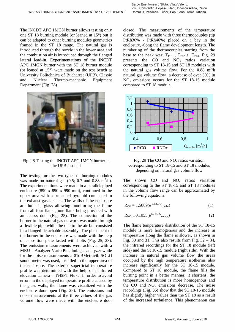
closed. The measurements of the temperature
distribution was made with three thermocouples (tip
PtRh30% - PtRh46%) placed on a bay in the
enclosure, along the flame development length. The
numbering of the thermocouples starting from the
base to the peak was: TFL1 , TFL2 si TFL3. Fig. 29
presents the CO and NOx ratios variation
corresponding to ST 18-15 and ST 18 modules with
the natural gas volume flow. For the 0.88 m3/h
natural gas volume flow a decrease of over 30% in
NOx emissions occurs for the ST 18-15 module
compared to ST 18 module.
0
0,2
0,4
0,6
0,8
1
1,2
0,4 0,6 0,8 1
Qcombs [m3/h]RCO RNOx
Fig. 29 The CO and NOx ratios variation
corresponding to ST 18-15 and ST 18 modules
depending on natural gas volume flow
The shown CO and NOx ratios variation
corresponding to the ST 18-15 and ST 18 modules
in the volume flow range can be approximated by
the following equations:
RCO = 1,5889(e-0,9297Q
combs) (1)
RNOx = 0,1055(e1,7473 Q
combs) (2)
The flame temperature distribution of the ST 18-15
module is more homogenous and the increase in
temperature along the flame is slower, as shown in
Fig. 30 and 31. This also results from Fig. 32 – 34,
the infrared recordings for the ST 18 module (left
side) and the St 18-15 module (right side). With the
increase in natural gas volume flow the areas
occupied by the high temperature isotherms also
increase significantly for the ST 18-15 module.
Compared to ST 18 module, the flame fills the
burning point in a better manner, it shortens, the
temperature distribution is more homogenous and
the CO and NOx emissions decrease. The noise
recordings (Fig. 35) show that the ST 18-15 module
has slightly higher values than the ST 18 as a result
of the increased turbulence. This phenomenon can
WSEAS TRANSACTIONS on ENVIRONMENT and DEVELOPMENT
Barbu Ene, Ionescu Silviu, Vilag Valeriu, Vilcu Constantin, Popescu Jeni, Ionescu Adina, Petcu Romulus, Prisecaru Tudor, Pop Elena, Toma Tatiana
ISSN: 1790-5079 414 Issue 6, Volume 6, June 2010

be observed particularly at high volume flows (0.88
m3/h).
0
0,2
0,4
0,6
0,8
1
1,2
1 1,5 2 2,5 3TFL No.
RT
FL
Fig. 30 Temperatures ratio variation in the flame
(for TFL1 , TFL2 si TFL3), corresponding to ST 18-15
and ST 18 modules, at Qcombs = 0.5 m3/h
0,75
0,8
0,85
0,9
1 1,5 2 2,5 3
TFL No.
RT
FL
Fig. 31 Temperatures ratio variation in the flame
(for TFL1 , TFL2 si TFL3), corresponding to ST 18-15
and ST 18 modules, at Qcombs = 0.88 m3/h
Fig. 32 Isotherms in infrared recording for ST 18
(left) and ST 18-15 (right) modules, at Qcombs = 0.5
m3/h
Fig. 33 Isotherms in infrared recording for ST 18
(left) and ST 18-15 (right) modules, at Qcombs = 0.7
m3/h
Fig. 34 Isotherms in infrared recording for ST 18
(left) and ST 18-15 (right) modules, at Qcombs = 0.88
m3/h
65
75
85
95
0,4 0,6 0,8 1
Qcombs [m3/h]ST 18 [dB]
ST 18-15 [dB]
Fig. 35 Noise variation corresponding to ST 18-15
and ST 18 modules, depending on natural gas
volume flow
The researches accomplished until now have shown
that the ST 18-15 module proves to be superior to
the ST 18 module, the numerical simulation data
being confirmed by the experimental ones obtained
on test bench.
4 Conclusions 1. The analysis in CFD environment of the
afterburning from the 2xST 18 – Suplacu de Barcau
Cogenerative Plant has shown that the performances
can be improved by redistributing the air in the
burner with the help of a concentrator. The
concentrator was installed to group 1 before the
afterburning.
2. After installing the concentrator, new researches
have been made at 2xST 18 – Suplacu de Barcau
Cogenerative Plant concerning the afterburning
installation at different operating regimes in terms
of emissions, noise, exterior superficial temperature
profile and energy quality.
3. Higher NOx emissions were recorded at group 2
operated in cogenerative regime, where there is no
concentrator installed. It is possible that additional
irregularities occur from the gas generator.
WSEAS TRANSACTIONS on ENVIRONMENT and DEVELOPMENT
Barbu Ene, Ionescu Silviu, Vilag Valeriu, Vilcu Constantin, Popescu Jeni, Ionescu Adina, Petcu Romulus, Prisecaru Tudor, Pop Elena, Toma Tatiana
ISSN: 1790-5079 415 Issue 6, Volume 6, June 2010

4. The noise locally recorded in the afterburning
area shows a slightly increase at group 2 with the
increase in the burned gases temperature. The noise
values in the afterburning area were commonly in
the 80 – 85 dB range.
5. At group 1 the areas occupied by the isotherms
increase with the increase in temperature in the
afterburning chamber outlet section in a large
operating regimes range.
6. At low loads for the case of the turbo-engine
operating with the heat recovery steam generator
the distortion coefficients variation from the
fundamental (THD). for current, is higher than 5%.
7. Based on experiments the burner of the
afterburning installation was redesigned for a new
burning module geometry (ST 18-R). The numerical
simulations have shown approximately three times
lower NOx emissions for the new burning module
(ST 18-R) compared to the old one (ST 18).
8. Test bench experimentations were made for an
intimate research of the processes and for
eliminating the disturbing factors from the
experimental data obtained at the cogenerative
plant. Tests were made for a modular burner on
natural gas and air in terms of emissions, noise and
temperature profile for the ST 18 and the ST 18-15
burning modules.
9. In the experimented natural gas volume flow (0.5
– 0.88 m3/h) with air results a decrease of over 30%
in NOx emissions for the ST 18-15 module
compared to ST 18. The flame fills better the
burning point, it shortens, the temperature
distribution is more homogenous and the CO and
NOx emissions decrease.
10. The analysis of the numerical and experimental
results in terms of emissions, noise and temperature
profile have shown that the ST 18-15 module is
superior to the ST 18, the numerical results being
validated by the experimental ones.
11. The researches will continue with test bench
experiments for natural gas and burned gases (fresh
air) for individual and multiple burning modules.
The burner optimized on test bench will also be
experimented in industrial conditions.
References:
[1] Barbu E., Petcu R., Vilag V., Research regarding
an afterburning system from a cogeneration power
plant on gas fuel, International Journal of Low
Carbon Technologies, Vol. 3/1, 2008, pp. 1-11
[2] Barbu E., Rosu I., Cazanele de abur ale centralei
cogenerative 2xST 18-Suplacu de Barcau’,
Conferinta “Producerea, transportul si utilizarea
energiei“, Cluj-Napoca, 13-14 Mai 2004 , p. 101-
107, ISBN 973-656-660-9
[3] Barbu E., Zavodnic F., Ionescu S., Vilag V.,
Integrated analysis system of afterburning in 2xST
18 cogeneration power plant, 3rd
International
Conference on Experiments/Process/System
Modeling/Simulation & Optimization (3rd IC-
EpsMsO), Athens, 8-11 July, 2009
[4] Cuciumita C., Barbu E,. Silivestru V., Petcu R.,
Vilag V., Numerical Analysis of Two Types of
Natural Gas Burners for the Comparison of NO
Emissions, Proceedings of the 3rd WSEAS Int. Conf.
On Waste Management, Water Pollution, Air
Pollution, Indoor Climate (WWAI `09), University
of La Laguna, Tenerife, Canary Islands, Spain, July
1-3, 2009, WSEAS Press, pp. 452-455
[5] Cuciumita C., Barbu E., Ionescu S., Prisecaru T.,
Vilag V., Vilcu C., The numerical and experimental
of the NO emissions for two types of natural gas
burners, Proceedings of the International
Conference on Energy and Environment
Technologies and Equipment, Bucharest, Romania,
April 20-22, 2010, WSEAS Press, pp. 27-30
[6] Barbu E., Ionescu S., Vilcu C., Prisecaru T.,
Petcu R., Vilag V., The integrated analysis of
afterburning in cogeneration power plant,
Proceedings of the International Conference on
Energy and Environment Technologies and
Equipment, Bucharest, Romania, April 20-22, 2010,
WSEAS Press, pp. 31-34
[7] Chicco G., Mancarella P., Performance
Evaluation of Cogeneration Systems: an Approach
Based on Incremental Indicators, Proceedings of the
6th WSEAS International Conference on Power
Systems, Lisbon, Portugal, September 22-24, 2006,
pp. 34-39
[8] Coman A., Boscoianu M., An Analysis of the
Mixing and Diffuse Burning Processes in the
Afterburning Chamber of a Scramjet, Proceedings
of the 4th WSEAS International Conference on
Fluid Mechanics and Aerodynamics, Elounda,
Greece, August 21-23, 2006, pp. 209-214
[9] Ghorbanzadeh D., Ghashami B.,
Khanmohammadi Sh., Exergy Analysis of NEKA-
IRAN Heat Recovery Steam Generator at Different
Ambient Temperatures, Proc. of the 3rd
IASME/WSEAS Int. Conf. on Energy, Environment,
Ecosystems and Sustainable Development, Agios
Nikolaos, Greece, July 24-26, 2007, pp. 493-498
[10] Chicco G., Mancarella P., Planning evaluation
and economic assessment of the electricity
production from small-scale trigeneration plants,
WSEAS Transactions om Power Systems, Vol. 1,
No.2, 2006. pp. 393-400
[11] Bejan A., Termodinamica tehnica avansata,
Editura Tehnica, Bucuresti, 1996, ISBN 973-31-
0994-0
WSEAS TRANSACTIONS on ENVIRONMENT and DEVELOPMENT
Barbu Ene, Ionescu Silviu, Vilag Valeriu, Vilcu Constantin, Popescu Jeni, Ionescu Adina, Petcu Romulus, Prisecaru Tudor, Pop Elena, Toma Tatiana
ISSN: 1790-5079 416 Issue 6, Volume 6, June 2010