integra · 5 step 6 • compression after all screws are locked in place, compress the integra...
TRANSCRIPT

SURGICAL TECHNIQUEIntegra™ Uni-CP™ Compression Plate

As the manufacturer of this device, Integra does not practice medicine and does not recommend this or any other surgical technique for use on a specific patient. The surgeon who performs any implant procedure is responsible for determining and using the appropriate techniques for implanting the device in each patient.
Indications
The Integra™ Uni-CP™ compression plate is indicated for fixation of bone fractures or for bone reconstruction. Examples include:
• Arthrodesis in hand or foot surgery• Fracture management in the foot or hand• Mono or bi-cortical osteotomies in the foot or hand• Distal or proximal metatarsal or metacarpal osteotomies• Fixation of osteotomies for Hallux Valgus treatment (such as Scarf, chevron, etc.)
The Uni-CP™ U-shaped plate is indicated for arthrodesis of the second and third cuneometatarsal and the inter-cuneiform second and third joints. The size and number of the plate(s) used should be adapted to the specific indication.
Contraindications
The implant should not be used in a patient who has currently, or who has a history of:
• Active infection or inflammation• Suspected or documented metal allergy or intolerance• Poor soft tissue quality at surgical site
Description
• Plate configurations:
– 2 hole design (17, 20, 25, and 30mm interaxis) – 4 hole design (20, 25, and 30mm interaxis)– 4 hole T-shape design (20mm interaxis)– 4 hole U-shape design (17, 19, and 21mm interaxis)
• 3.5mm diameter range of screw lengths:
– 12-34mm in 2mm increments
• Surfix® Locking Technology
• Material: Stainless Steel
Surgical Site Preparation
The articular surfaces should be prepared using standard technique to resect the necessary amount of cartilage and, if necessary, to remove bone graft material.
Obtain adequate reduction and provisional fixation using guide wires or reduction forceps.
Surgical TechniqueThis technique has been developed in conjunction with Stephen Conti, MD.
2
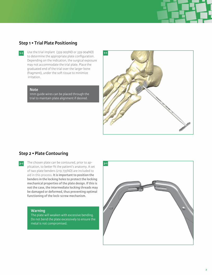
Step 1 • Trial Plate Positioning
Step 2 • Plate Contouring
Use the trial implant (339 005ND or 339 004ND) to determine the appropriate plate configuration. Depending on the indication, the surgical exposure may not accommodate the trial plate. Place the graduated end of the trial over the larger bone (fragment), under the soft tissue to minimize irritation.
The chosen plate can be contoured, prior to ap-plication, to better fit the patient’s anatomy. A set of two plate benders (219 735ND) are included to aid in this process. It is important to position the benders in the locking holes to protect the locking mechanical properties of the plate design. If this is not the case, the intermediate locking threads may be damaged or deformed, thus preventing optimal functioning of the lock-screw mechanism.
1 - 1
2 - 1
1- 1
2- 1
WarningThe plate will weaken with excessive bending. Do not bend the plate excessively to ensure the metal is not compromised.
Note1mm guide wires can be placed through the trial to maintain plate alignment if desired.

3
Step 3 • Drill Guides
Step 4 • Implant Positioning
Insert the drill guides (219 635ND) into the appropri-ately contoured plate. The screwdrivers (219 835ND) can be used to ease introduction into the threaded hole. Make sure that each guide is fully seated in the plate to maintain proper alignment.
Position the plate in the desired location. An implant holder (339 003ND) can be secured to any one of the drill guides to aid in this process. 1mm guide wires can then be inserted into the wire holes in the plate for temporary fixation.
3 - 1
4 - 1
3- 1
4- 1
NoteIf 1mm guide wires were introduced through the trial instrument, the plate can be intro-duced over them, positioning the guide wires through the holes in the plate.
NoteThe drill guides are slotted to allow for the removal of bodily debris during the drilling process.

4
Step 5 • Screw Insertion
A B
C D
E F
WarningWhen using the 4-hole plate, always place diagonal screws first to maintain accurate placement and optimally contour the plate to the bone surface.
WarningSteps A through F should be completed for each screw before beginning preparation of the subsequent screw(s). If not, the axes of the screw and the prepared hole may be misaligned.
Place the lock-screw on the appropriate screwdriver. The lock-screw should be inserted after each screw, and before preparation and insertion of the subsequent screw. This prevents potential damage to the thread.
Fully seat the lock-screw using the screwdriver (over tighten-ing the lock-screw provides no additional benefit and increases the chances of strip-ping). When it is fully inserted, the lock-screw should be flush with the top of the plate.
Remove the drill guide and chamfer the drill hole with the screwdriver (219 835ND). Ensure that the threaded hole is not damaged when performing the chamfering.
Prepare holes with the 2.7 mm drill (219 535ND) through the drill guide. The screw length can be determined from the calibrated scale on the drill. The depth is determined from the top side of the drill guide.
Insert the screw (286 312SND-286 340SND) into the pre-pared hole and tighten until the plate is fully seated in the plate. Clean the threaded hole before and after introducing the screw. (Unlike a traditional locking mechanism, the screw can be continually tightened to contour the plate to the bone.)
Alternately, measure the nec-essary screw length using the depth gauge (219 336ND). It can be used with or without the drill guide. Each depth gauge has two sets of markings to use with or without the drill guide.

5
Step 6 • Compression
After all screws are locked in place, compress the Integra Uni-CP compression plate using the com-pression forcep (spreading) instrument (339 001ND). Upon opening the diamond designed bridge, the compressive forces will pull the ends of the plate toward one another.
Compress the Uni-CP U-shape compression plate using the compression forcep (spreading) instrument (339001ND). The transverse intercuneiform diamond bridge should be compressed first, followed by compression of the tarsometatarsal segments. Upon opening the diamond designed bridge, the compressive forces will pull the ends of the plate toward one another.
6 - 1 6- 1
SPEC
IFIC
U-S
hape
Pla
te

6
X-Rays

For more information or to place an order, please contact:Integra n 311 Enterprise Drive, Plainsboro, NJ 08536877-444-1122 USA n 609-936-5400 outside USA n 866-800-7742 faxintegralife.com
Catalog Number
Catalog Number
Uni-CP Compression Plate
Sterile Stainless Steel ScrewsDiam. 3.5mm + Lock-Screw
330 217SND 2 holes 17mm interaxis330 220SND 2 holes 20mm interaxis330 225SND 2 holes 25mm interaxis330 230SND 2 holes 30mm interaxis
330 420SND 4 holes 20mm interaxis330 425SND 4 holes 25mm interaxis330 430SND 4 holes 30mm interaxis
330 030SND 4 holes 20mm interaxis T-shape
330 021SND 4 holes 17mm interaxis U-shape 330 023SND 4 holes 19mm interaxis U-shape330 025SND 4 holes 21mm interaxis U-shape
286 312SND Length 12mm286 314SND Length 14mm286 316SND Length 16mm286 318SND Length 18mm286 320SND Length 20mm286 322SND Length 22mm286 324SND Length 24mm286 326SND Length 26mm286 328SND Length 28mm286 330SND Length 30mm286 332SND Length 32mm286 334SND Length 34mm
186 300SND Lock-screw
Description
Description
Catalog Number
Catalog Number
Instrument Container
Instrumentation
339 900ND Container339 910ND Base339 901ND Lid339 911ND Module
219 835ND Screwdriver Hex diam. 2.0mm219 435ND Screwdriver AO Hex diam. 2.0mm219 635ND Drilling guide diam. 2.7mm219 535ND Drill AO diam. 2.7mm219 735ND Bending forceps diam. 3.5mm hole219 336ND Depth gauge diam. 3.5mm screws339 001ND Compression plate forceps (spreader)339 005ND Trial implant 2 hole and 4 hole339 004ND Trial implant T and U plate339 003ND Implant holder115 101ND K-wire, 100mm
Description
Description
Integra™
Uni-CP™ Compression Plate
Surfix is a registered trademark of Integra LifeSciences Corporation or its subsidiaries. Uni-CP, Integra, and the Integra logo are trademarks of Integra LifeSciences Corporation or its subsidiaries. ©2011 Integra LifeSciences Corporation. All rights reserved. Printed in the USA 5k ER5368-03/12