00. initial installation manual ap integra€¦ · initial installation manual ap integra (er-n) /...
TRANSCRIPT
DOC14003D
Ref. 0147630D
TP PAGE : 1
Date of rev.: FEB 12/2015
Revision 03
First issue: JUN 06/2014
Orolia S.A.S. - A Company of the McMurdo Group
Emergency Locator Transmitters
INITIAL INSTALLATION MANUAL
AP INTEGRA (ER-N) / AP-H INTEGRA (ER-N)With built-in GPS and Integral Antenna
© O
rolia
S.A
.S. :
Thi
s do
cum
ent i
s th
e pr
oper
ty o
f Oro
lia S
.A.S
. and
con
tain
s pr
oprie
tary
and
con
fiden
tial i
nfor
mat
ion.
The
doc
umen
t is
loan
ed o
n th
e ex
pres
s co
nditi
on th
at n
eith
er th
e do
cum
ent i
tsel
f nor
the
info
rmat
ion
cont
aine
d th
erei
n sh
all b
e di
sclo
sed
with
out t
he e
xpre
ss c
onse
nt o
f Oro
lia S
.A.S
. and
that
the
info
rmat
ion
shal
l not
be
used
by
the
reci
pien
t with
out p
rior
writ
ten
acce
ptan
ce b
y O
rolia
S.A
.S..
Fur
ther
mor
e, th
e do
cum
ent s
hall
be r
etur
ned
imm
edia
tely
to O
rolia
S.A
.S. u
pon
requ
est.

Users are kindly requested to notify Orolia S.A.S. of any discrepancy, omission or error found in this manual.Please report to our customer support:
E-mail: [email protected].: +33 (0)2 97 02 49 00
INITIAL INSTALLATION MANUAL AP INTEGRA (ER-N) / AP-H INTEGRA (ER-N)
TABLE OF CONTENTSIntroduction ........................................................................................... 1KANNAD INTEGRA System Presentation ............................................ 1
System overview ................................................................................................... 1Transmitter and bracket ......................................................................................... 3INTEGRA ARINC e-NAV ....................................................................................... 4Remote Control Panels (RCP) ............................................................................... 4
RC100 KIT .......................................................................................................... 5RC200 ................................................................................................................. 5RC300 / RC300 NVG .......................................................................................... 6RC310 ................................................................................................................. 6RC600 NVG ........................................................................................................ 7RC800 ................................................................................................................. 7
External antennas .................................................................................................. 8Registration ........................................................................................... 9
General .................................................................................................................. 9Registration in USA ............................................................................................... 9Registration in Canada ........................................................................................ 10
ELT Installation ................................................................................... 11ELT and bracket installation recommendations ................................................... 11
FAA Recommendations .................................................................................... 11TSO C126b Section a (3), Application Data Requirements .............................. 11RTCA DO-182 Recommandations .................................................................... 11RTCA DO-204a Requirements ......................................................................... 11
ELT location recommendations ........................................................................... 12Bracket installation procedure ............................................................................. 12
Determine location and direction ....................................................................... 12Fix the mounting bracket ................................................................................... 14
INTEGRA ARINC e-NAV and ELT Installation Procedure ................................... 16Optional Programming Dongle Installation ........................................................ 16ELT Installation ................................................................................................. 18ELT Fixing ......................................................................................................... 20
External Antenna Installation .............................................................. 22Antenna Installation Recommendations .............................................................. 22
FAA Recommendations .................................................................................... 22RTCA DO-204 Recommendations for external antenna location ..................... 22External Antenna Location ................................................................................ 22
Antenna installation procedure ............................................................................ 23INTEGRA ARINC e-NAV, Connection to ELT ..................................... 25RCP Installation .................................................................................. 25
RCP Installation Recommendations .................................................................... 25RCP Installation Procedure ................................................................................. 25
RC100 ............................................................................................................... 26RC200 ............................................................................................................... 28RC300 / RC300-NVG ........................................................................................ 30RC310 ............................................................................................................... 31RC600 NVG ...................................................................................................... 32RC800 ............................................................................................................... 33
TOC PAGE: 1
FEB 12/2015
INITIAL INSTALLATION MANUAL AP INTEGRA (ER-N) / AP-H INTEGRA (ER-N)
TABLE OF CONTENTS
Outside Buzzer Installation ................................................................. 33ELT Connection .................................................................................. 34First power up procedure .................................................................... 35
ELT operational tests .......................................................................................... 35RCP operational tests ......................................................................................... 36406 and 121.5 MHz transmission test ................................................................. 37
406 MHz ........................................................................................................... 37121.5 MHz ........................................................................................................ 37
Outline dimensions and weights ......................................................... 39Wiring diagrams .................................................................................. 55Compatibility list for INTEGRA ELTs System ..................................... 62
Mounting brackets ............................................................................................... 62Remote control panels (RCP) ............................................................................. 62Connector for RCP Cable INTEGRA ARINC e-NAV Cable ................................ 62Programming Dongle .......................................................................................... 62Outside buzzer .................................................................................................... 62Auxiliary Antenna / External Antennas ................................................................ 63
TOC PAGE: 2
FEB 12/2015
INITIAL INSTALLATION MANUAL AP INTEGRA (ER-N) / AP-H INTEGRA (ER-N)
1. Introduction
The instructions in this manual provide the information necessary for the initial installation of AP INTEGRA (ER-N) / AP-H INTEGRA (ER-N) ELT system and INTEGRA ARINC e-NAV interface.
CAUTION: INTEGRA (ER-N) ELTs shall always be connected to an INTEGRA ARINC e-NAV. Installing an INTEGRA (ER-N) ELT without INTEGRA ARINC e-NAV is not authorized.
2. KANNAD INTEGRA System Presentation
A. System overview
NOTE: for details of approved part number of AP INTEGRA / AP-H INTEGRA system, Refer to Section 13. Compatibility list for INTEGRA ELTs System, page 61.
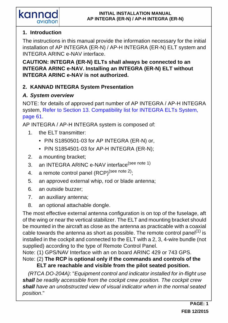
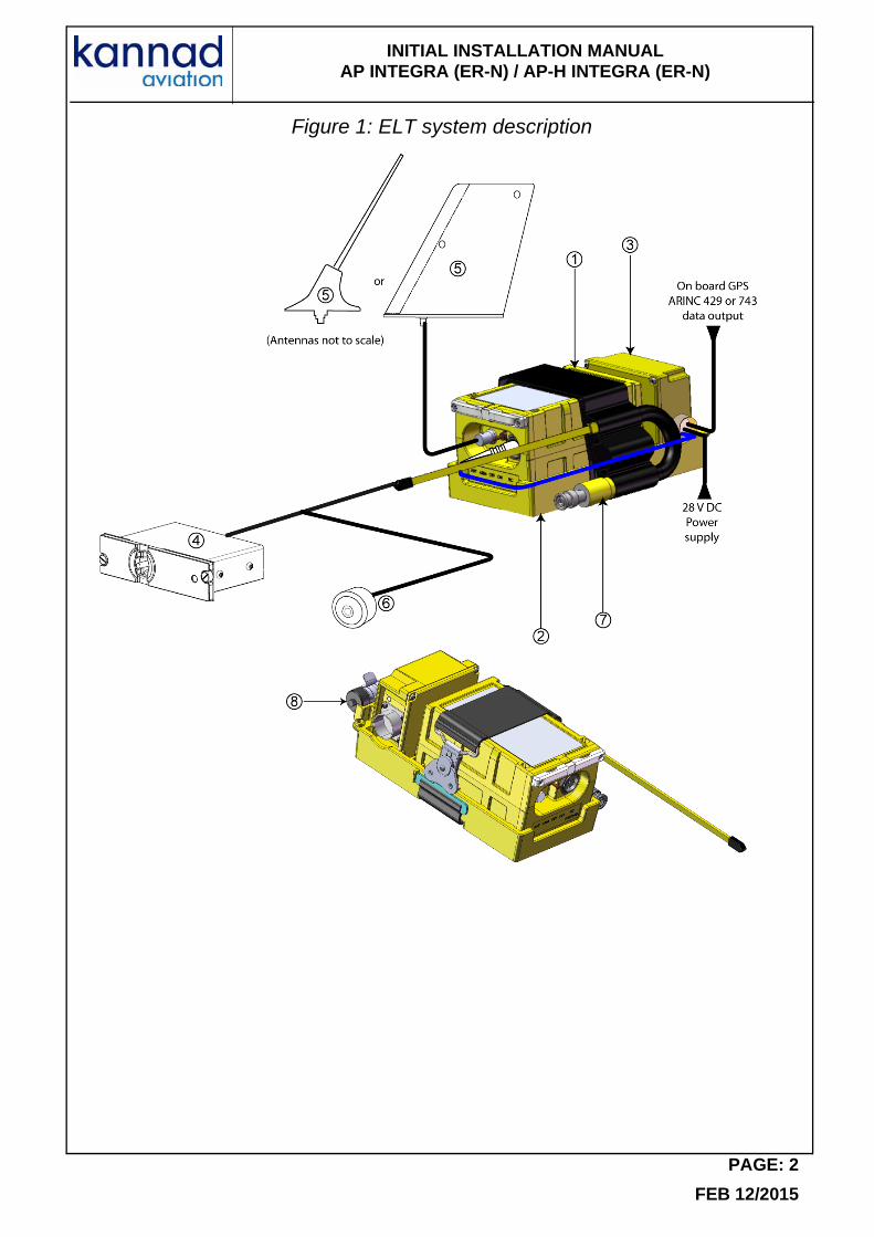
AP INTEGRA / AP-H INTEGRA system is composed of:
1. the ELT transmitter:
• P/N S1850501-03 for AP INTEGRA (ER-N) or,
• P/N S1854501-03 for AP-H INTEGRA (ER-N);
2. a mounting bracket;
3. an INTEGRA ARINC e-NAV interface(see note 1)
4. a remote control panel (RCP)(see note 2);
5. an approved external whip, rod or blade antenna;
6. an outside buzzer;
7. an auxiliary antenna;
8. an optional attachable dongle.
The most effective external antenna configuration is on top of the fuselage, aft of the wing or near the vertical stabilizer. The ELT and mounting bracket should be mounted in the aircraft as close as the antenna as practicable with a coaxial cable towards the antenna as short as possible. The remote control panel(1) is installed in the cockpit and connected to the ELT with a 2, 3, 4-wire bundle (not supplied) according to the type of Remote Control Panel.Note: (1) GPS/NAV Interface with an on board ARINC 429 or 743 GPS.Note: (2) The RCP is optional only if the commands and controls of the
ELT are reachable and visible from the pilot seated position.
(RTCA DO-204A): "Equipment control and indicator installed for in-flight use shall be readily accessible from the cockpit crew position. The cockpit crew shall have an unobstructed view of visual indicator when in the normal seated position."
PAGE: 1
FEB 12/2015
INITIAL INSTALLATION MANUAL AP INTEGRA (ER-N) / AP-H INTEGRA (ER-N)
Figure 1: ELT system description
PAGE: 2
FEB 12/2015
INITIAL INSTALLATION MANUAL AP INTEGRA (ER-N) / AP-H INTEGRA (ER-N)
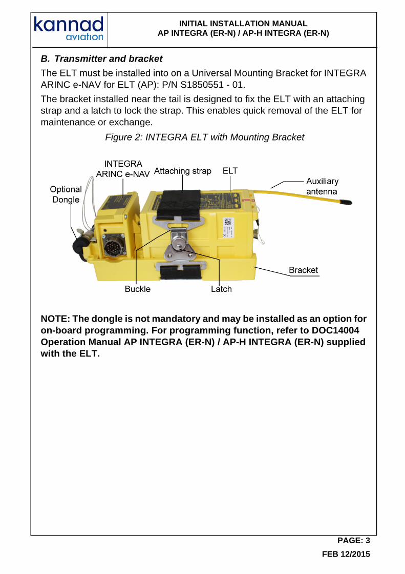
B. Transmitter and bracket
The ELT must be installed into on a Universal Mounting Bracket for INTEGRA ARINC e-NAV for ELT (AP): P/N S1850551 - 01.
The bracket installed near the tail is designed to fix the ELT with an attaching strap and a latch to lock the strap. This enables quick removal of the ELT for maintenance or exchange.
Figure 2: INTEGRA ELT with Mounting Bracket
NOTE: The dongle is not mandatory and may be installed as an option for on-board programming. For programming function, refer to DOC14004 Operation Manual AP INTEGRA (ER-N) / AP-H INTEGRA (ER-N) supplied with the ELT.
PAGE: 3
FEB 12/2015
INITIAL INSTALLATION MANUAL AP INTEGRA (ER-N) / AP-H INTEGRA (ER-N)
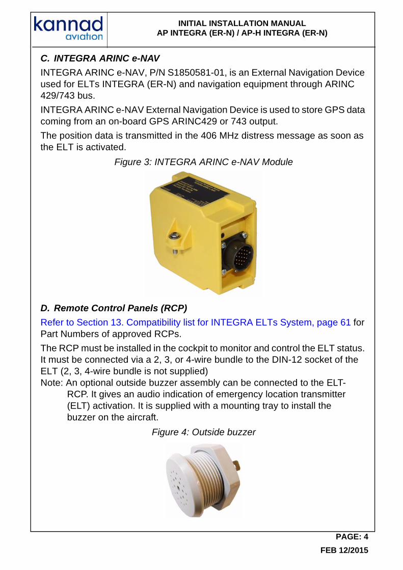
C. INTEGRA ARINC e-NAV
INTEGRA ARINC e-NAV, P/N S1850581-01, is an External Navigation Device used for ELTs INTEGRA (ER-N) and navigation equipment through ARINC 429/743 bus.
INTEGRA ARINC e-NAV External Navigation Device is used to store GPS data coming from an on-board GPS ARINC429 or 743 output.
The position data is transmitted in the 406 MHz distress message as soon as the ELT is activated.
Figure 3: INTEGRA ARINC e-NAV Module
D. Remote Control Panels (RCP)
Refer to Section 13. Compatibility list for INTEGRA ELTs System, page 61 for Part Numbers of approved RCPs.
The RCP must be installed in the cockpit to monitor and control the ELT status. It must be connected via a 2, 3, or 4-wire bundle to the DIN-12 socket of the ELT (2, 3, 4-wire bundle is not supplied)Note: An optional outside buzzer assembly can be connected to the ELT-
RCP. It gives an audio indication of emergency location transmitter (ELT) activation. It is supplied with a mounting tray to install the buzzer on the aircraft.
Figure 4: Outside buzzer
PAGE: 4
FEB 12/2015
INITIAL INSTALLATION MANUAL AP INTEGRA (ER-N) / AP-H INTEGRA (ER-N)
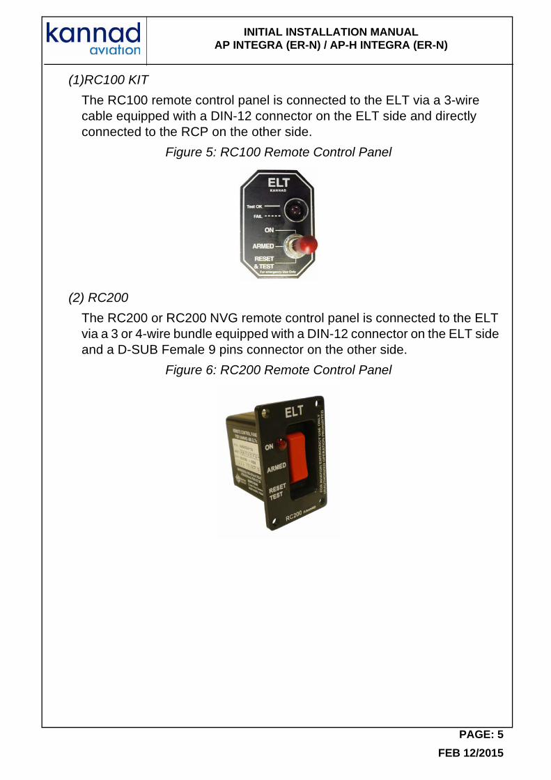
(1)RC100 KIT
The RC100 remote control panel is connected to the ELT via a 3-wire cable equipped with a DIN-12 connector on the ELT side and directly connected to the RCP on the other side.
Figure 5: RC100 Remote Control Panel
(2) RC200
The RC200 or RC200 NVG remote control panel is connected to the ELT via a 3 or 4-wire bundle equipped with a DIN-12 connector on the ELT side and a D-SUB Female 9 pins connector on the other side.
Figure 6: RC200 Remote Control Panel
PAGE: 5
FEB 12/2015
INITIAL INSTALLATION MANUAL AP INTEGRA (ER-N) / AP-H INTEGRA (ER-N)
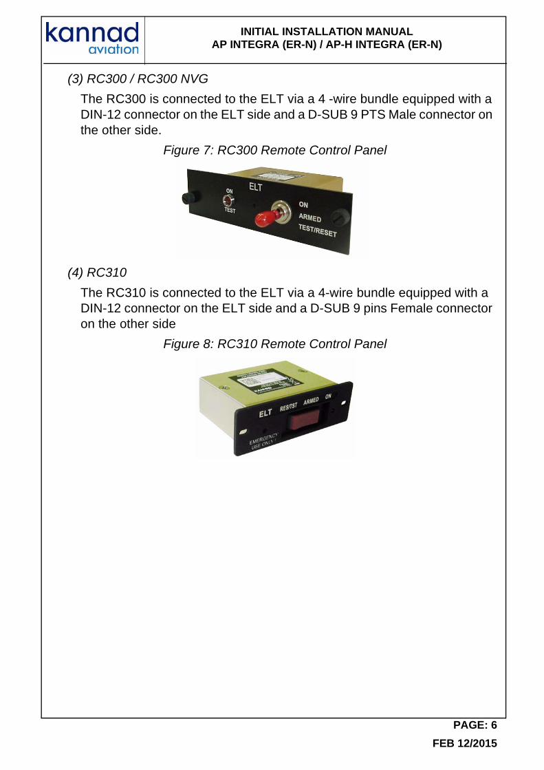
(3) RC300 / RC300 NVG
The RC300 is connected to the ELT via a 4 -wire bundle equipped with a DIN-12 connector on the ELT side and a D-SUB 9 PTS Male connector on the other side.
Figure 7: RC300 Remote Control Panel
(4) RC310
The RC310 is connected to the ELT via a 4-wire bundle equipped with a DIN-12 connector on the ELT side and a D-SUB 9 pins Female connector on the other side
Figure 8: RC310 Remote Control Panel
PAGE: 6
FEB 12/2015
INITIAL INSTALLATION MANUAL AP INTEGRA (ER-N) / AP-H INTEGRA (ER-N)
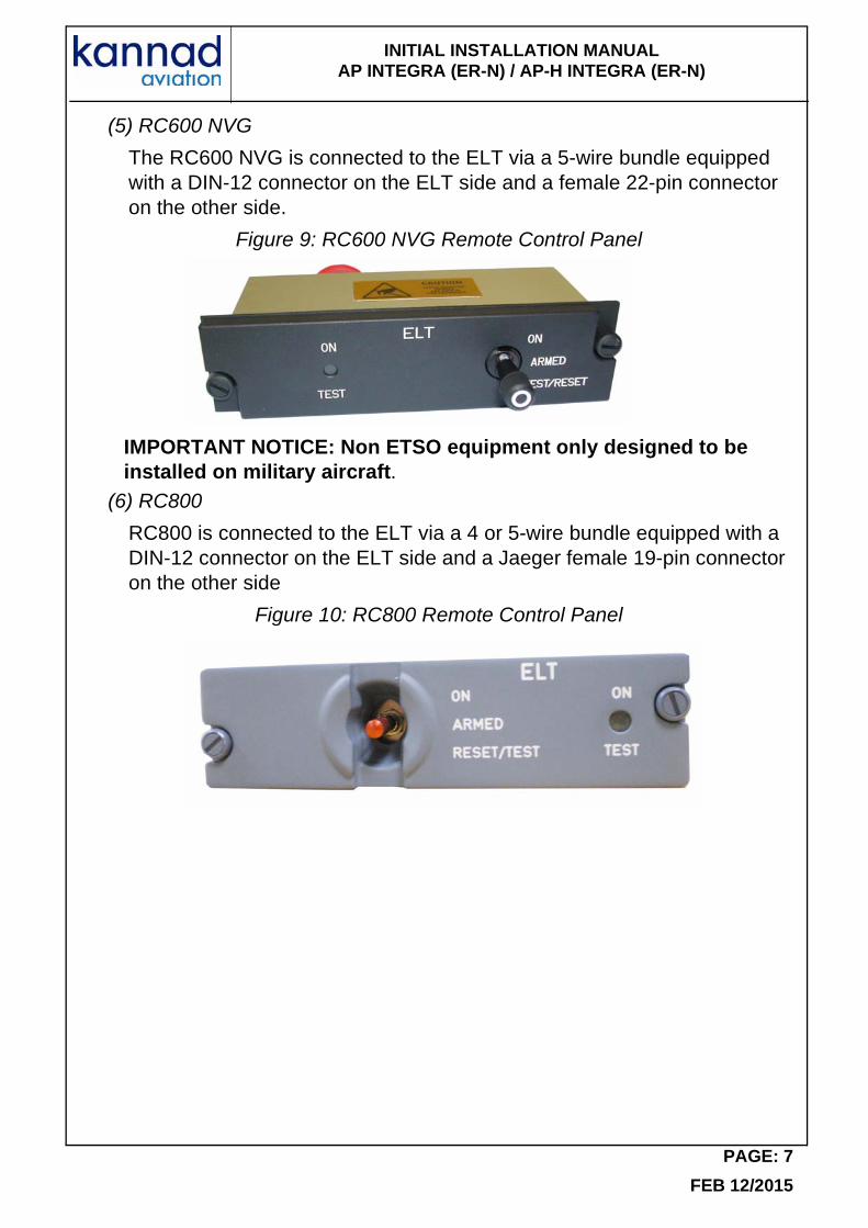
(5) RC600 NVG
The RC600 NVG is connected to the ELT via a 5-wire bundle equipped with a DIN-12 connector on the ELT side and a female 22-pin connector on the other side.
Figure 9: RC600 NVG Remote Control Panel
IMPORTANT NOTICE: Non ETSO equipment only designed to be installed on military aircraft.
(6) RC800
RC800 is connected to the ELT via a 4 or 5-wire bundle equipped with a DIN-12 connector on the ELT side and a Jaeger female 19-pin connector on the other side
Figure 10: RC800 Remote Control Panel
PAGE: 7
FEB 12/2015
INITIAL INSTALLATION MANUAL AP INTEGRA (ER-N) / AP-H INTEGRA (ER-N)
PAGE: 8
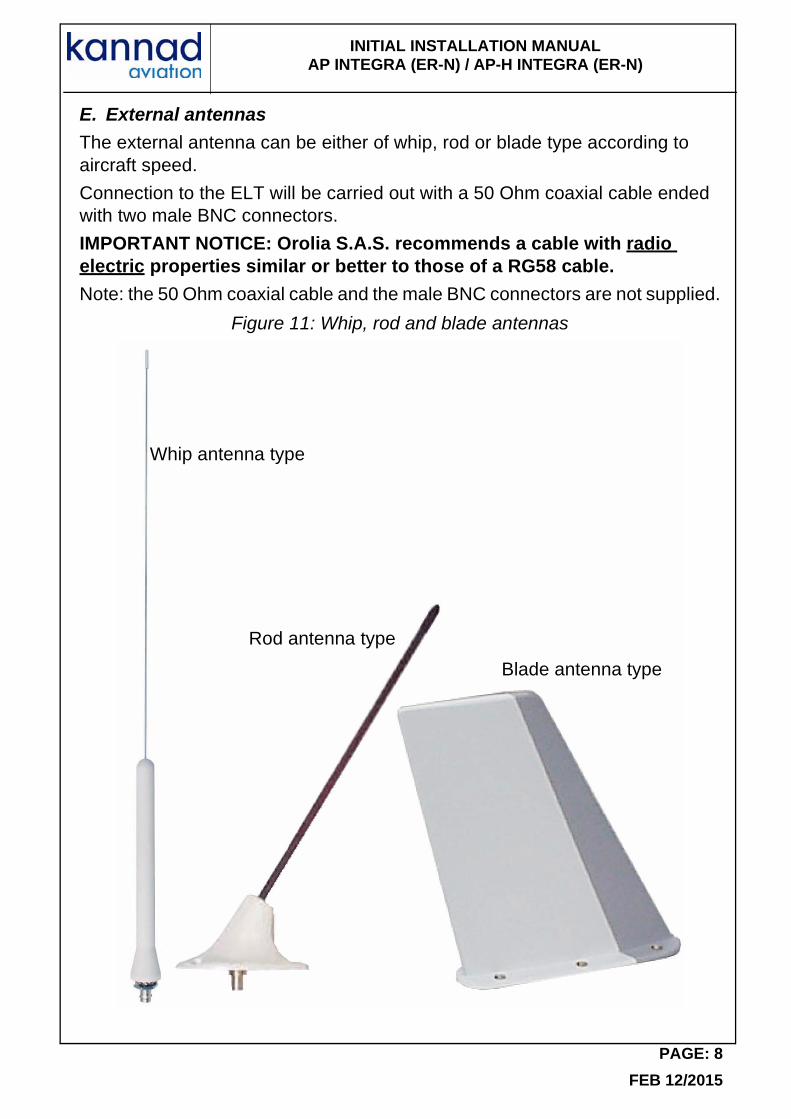
E. External antennas
The external antenna can be either of whip, rod or blade type according to aircraft speed.
Connection to the ELT will be carried out with a 50 Ohm coaxial cable ended with two male BNC connectors.
IMPORTANT NOTICE: Orolia S.A.S. recommends a cable with radio electric properties similar or better to those of a RG58 cable.
Note: the 50 Ohm coaxial cable and the male BNC connectors are not supplied.
Figure 11: Whip, rod and blade antennas
Whip antenna type
Rod antenna type
Blade antenna type
FEB 12/2015
INITIAL INSTALLATION MANUAL AP INTEGRA (ER-N) / AP-H INTEGRA (ER-N)
3. Registration
A. General
The ELT must be registered prior to installation on board.
When a 406 MHz ELT is installed in an aircraft, it is imperative that the aircraft owner register the ELT. Each 406 MHz ELT contains a unique identification code that is transmitted to the satellite. This helps the “Rescue Coordination Center” (RCC) determine whether an emergency has actually occurred. The unique identification permits accessing a data base.
The registration card available from the local registration authority must be completed and returned to this authority.
Any change of ownership shall also be declared and registered with the local registration authority.
B. Registration in USA
Mail or Fax your registration form to:
SARSAT BEACON REGISTRATION
NOAA
NSOF, E/SPO53
1315 East West Hwy
Silver Spring, MD 20910
or Save Time! Register your beacon online at:
www.beaconregistration.noaa.gov
All online registrations will be entered into the National 406 MHz Beacon Registration Database on the same day of entry. Registration forms received via postal mail will be entered within 2 business days of receipt. For online registrations, a confirmation letter with your completed registration information form will be sent immediately via e-mail or fax (if provided). Confirmation letters sent via postal mail should arrive within two weeks. Once your registration confirmation is received, please review all information. Any changes or updates to your registration information can be done via the internet, fax, e-mail or postal mail. If you do not receive your registration confirmation from NOAA on the same day you submit it over the internet or within two weeks if you submit it by postal mail, please call NOAA toll-free at: 1-888-212-SAVE (7283) or
301-817-4515 for assistance.
After initial registration (or re-registration) you will receive a NOAA Proof of Registration Decal by postal mail. This decal is to be affixed to the beacon and should be placed in such a way that it is clearly visible. If for some reason you do not receive the registration decal within two weeks, please call NOAA
PAGE: 9
FEB 12/2015

INITIAL INSTALLATION MANUAL AP INTEGRA (ER-N) / AP-H INTEGRA (ER-N)
toll-free at: 1-888-212-SAVE (7283) or 301-817-4515.
Failure to register, re-register (as required every two years), or to notify NOAA of any changes to the status of your 406 MHz beacon could result in penalties and/or fines being issued under Federal Law. The owner or user of the beacon is required to notify NOAA of any changes to the registration information at any time. By submitting this registration the owner, operator, or legally authorized agent declares under penalty of law that all information in the registration information is true, accurate, and complete. Providing information that is knowingly false or inaccurate may be punishable under Federal Statutes. Solicitation of this information is authorized by Title 47 - Parts 80, 87, and 95 of the U.S. Code of Federal Regulations (CFR). Additional registration forms can be found on the NOAA-SARSAT website at:
www.sarsat.noaa.gov or at: www.beaconregistration.noaa.gov
C. Registration in Canada
Beacon information is held in the Canadian Beacon Registry maintained by the National Search and Rescue Secretariat for use in search and rescue operations. Online access to the Registry is available for all beacon owners to register new beacons or to update their beacon information. You can add or update your beacon information by accessing the registry directly, sending in a completed registration form or by talking to one of our beacon registry representatives.
You can access the registry:• online: www.canadianbeaconregistry.com• by email: [email protected]• by fax: 1-613-996-3746• by telephone: 1-800-727-9414 or 1-613-996-1616
The registration information must be updated when the aircraft ownership changes as per the Canadian Airworthiness Notice AN B029 (refer to following link):
http://www.nss.gc.ca/site/Emergency_Beacons/canadian_beacon_registry_e.asp
Additional information and registration forms can be found on the Canadian NSS website at:
http://www.nss.gc.ca/site/cospas-sarsat/INTRO_e.asp
PAGE: 10
FEB 12/2015
INITIAL INSTALLATION MANUAL AP INTEGRA (ER-N) / AP-H INTEGRA (ER-N)
4. ELT Installation
A. ELT and bracket installation recommendations
The ELT shall not be installed within 30cm (1 ft.) of a compass or flux gate.
The distance between ELT and antenna shall be determined so that, according to the coaxial cable chosen.
The ELT front panel should be easily accessible to connect the external antenna and the remote control panel device and to check the ELT good operation (controls and lights).
(1)FAA Recommendations
Installation must be made by qualified personnel in accordance with FAA regulations. Duplicating a previous installation may not be acceptable. Refer to:
FAA - Advisory Circular 43.13-2B (Acceptable Methods, Techniques, and Practices - Aircraft Alterations), specifically, Chapters 1, 2, 11 and 13.
(2) TSO C126b Section a (3), Application Data Requirements
Limitations:
"This article meets the minimum performance and quality control standards required by a technical standard order (TSO). Installation of this article requires separate approval".
(3) RTCA DO-182 Recommendations
"All ELT system components which must survive to a crash intact,...should be attached to the airframe in such a manner that the attachment system can support a 100g load... in the plus and minus directions of the three principal axes of the aircraft."
(4) RTCA DO-204a Requirements
"The ELT unit shall be mounted to primary aircraft load-carrying structures such as trusses, bulkheads, longerons, spars or floor beams (not aircraft skin) or a structure that meets the requirements of the following test. The mounts shall have a maximum static local deflection no greater than 2.5 mm when a force of 450 Newtons (l00 lbf) is applied to the mount in the most flexible direction. Deflection measurements shall be made with reference to another part of the airframe not less than 0.3 m or more than 1.0 m from the mounting location. Typical approaches for adding shelf and rail platform mounting provisions to aircraft structure as shown an FAA Advisory circular 43.13-2(), Chapter 2."
PAGE: 11
FEB 12/2015
INITIAL INSTALLATION MANUAL AP INTEGRA (ER-N) / AP-H INTEGRA (ER-N)
B. ELT location recommendations
Orolia S.A.S. provides additional safety functions in the INTEGRA ELTs such as built-in GPS and integral antenna.
If the link towards the external antenna is defective, the integral antenna, protected by the high resistance housing of the ELT, may help to establish a link towards the satellites COSPAS-SARSAT system.
However, Orolia S.A.S. cannot control neither the environment of the ELT when a crash occurs nor a too important metallic structure around the ELT. For these reasons, Orolia S.A.S. recommends to install the ELT in a location in such a way that the vertical extension of the integral antenna is exposed to a RF transparent window.
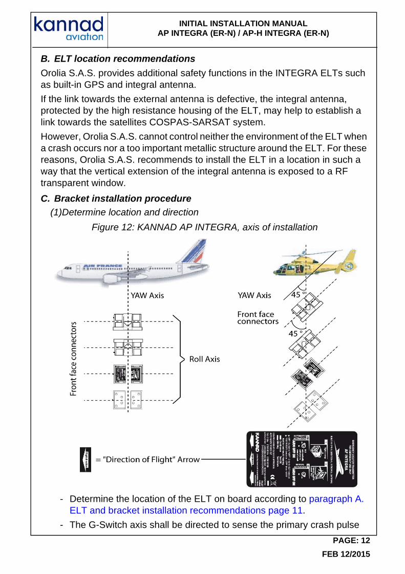
C. Bracket installation procedure(1)Determine location and direction
Figure 12: KANNAD AP INTEGRA, axis of installation
- Determine the location of the ELT on board according to paragraph A. ELT and bracket installation recommendations page 11.
- The G-Switch axis shall be directed to sense the primary crash pulse
PAGE: 12
FEB 12/2015
INITIAL INSTALLATION MANUAL AP INTEGRA (ER-N) / AP-H INTEGRA (ER-N)
along the longitudinal axis of the aircraft. Reference to the G-Switch is given by the arrow "Flight direction" on the label affixed to the top of the ELT.
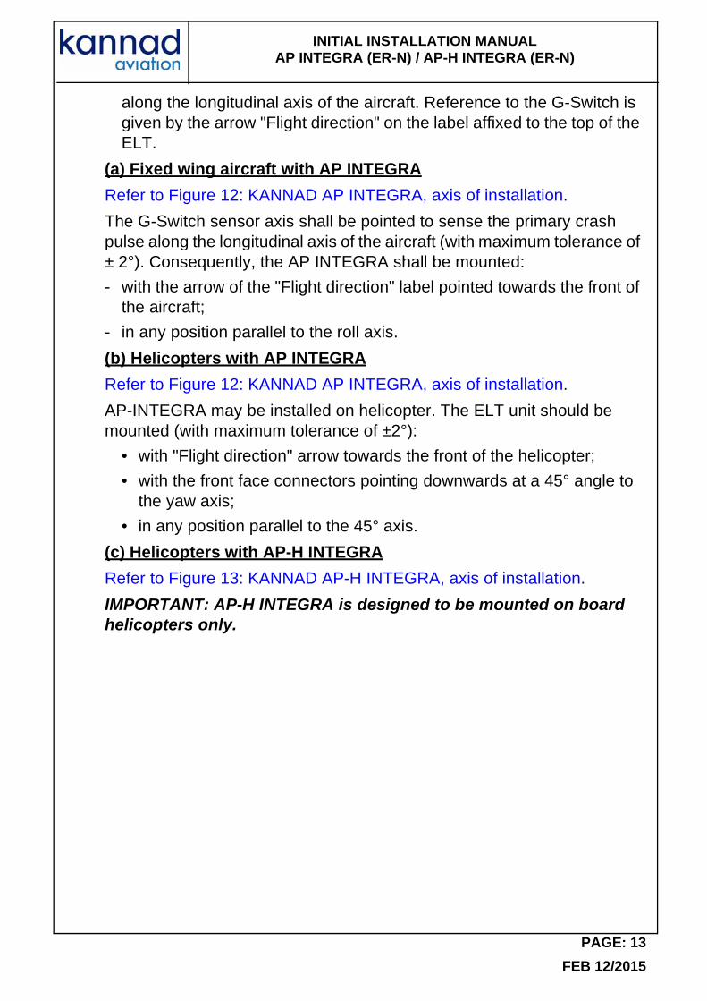
(a) Fixed wing aircraft with AP INTEGRA
Refer to Figure 12: KANNAD AP INTEGRA, axis of installation.
The G-Switch sensor axis shall be pointed to sense the primary crash pulse along the longitudinal axis of the aircraft (with maximum tolerance of ± 2°). Consequently, the AP INTEGRA shall be mounted:
- with the arrow of the "Flight direction" label pointed towards the front of the aircraft;
- in any position parallel to the roll axis.
(b) Helicopters with AP INTEGRA
Refer to Figure 12: KANNAD AP INTEGRA, axis of installation.
AP-INTEGRA may be installed on helicopter. The ELT unit should be mounted (with maximum tolerance of ±2°):
• with "Flight direction" arrow towards the front of the helicopter;
• with the front face connectors pointing downwards at a 45° angle to the yaw axis;
• in any position parallel to the 45° axis.
(c) Helicopters with AP-H INTEGRA
Refer to Figure 13: KANNAD AP-H INTEGRA, axis of installation.
IMPORTANT: AP-H INTEGRA is designed to be mounted on board helicopters only.
PAGE: 13
FEB 12/2015

INITIAL INSTALLATION MANUAL AP INTEGRA (ER-N) / AP-H INTEGRA (ER-N)
Figure 13: KANNAD AP-H INTEGRA, axis of installation
The "Direction of Flight " arrow shall point towards the front or the bottom of the helicopter (and not pointing 45° downwards):
- If the AP-H INTEGRA is installed with the "Direction of Flight " arrow pointing towards the front of the helicopter, the ELT shall be mounted with the upper side pointing towards the top of the helicopter.
- If the AP-H INTEGRA is installed with the "Direction of Flight " arrow pointing towards the bottom of the helicopter, the ELT shall be installed with the lower side pointing towards the front of the helicopter
(2) Fix the mounting bracket
- Drill 4 holes Ø 6 mm in the aircraft structure according to "Drilling mask": Refer to Mounting Bracket, Outline dimensions, page 41 [Inner holes (1, 2, 3, 4) should be preferred].
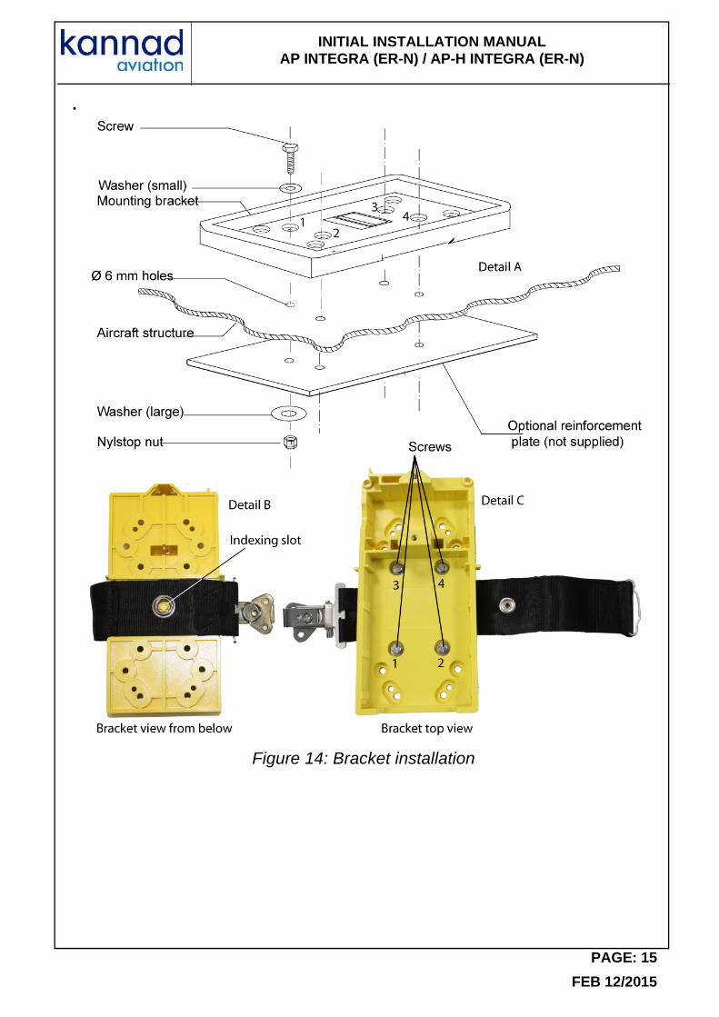
- If the attachment system is not solid enough to withstand a 100G load ([ELT + INTEGRA ARINC e-NAV + bracket] weight x 100) on the bracket, a reinforcement plate (not supplied) should be installed as shown Figure 14: Bracket installation in order to be compliant with the RTCA DO-182 recommendation (see Detail A).
- Place the strap onto the back side of the mounting bracket. Engage the hole of the strap onto the indexing slot of the mounting bracket (see Detail B)
- Fix the bracket with the 4 screws, 8 washers and 4 nylstop nuts supplied.IMPORTANT: tighten to a torque between 4 and 5 Newton x meter.
PAGE: 14
FEB 12/2015
INITIAL INSTALLATION MANUAL AP INTEGRA (ER-N) / AP-H INTEGRA (ER-N)
.
Figure 14: Bracket installation
PAGE: 15
FEB 12/2015
INITIAL INSTALLATION MANUAL AP INTEGRA (ER-N) / AP-H INTEGRA (ER-N)
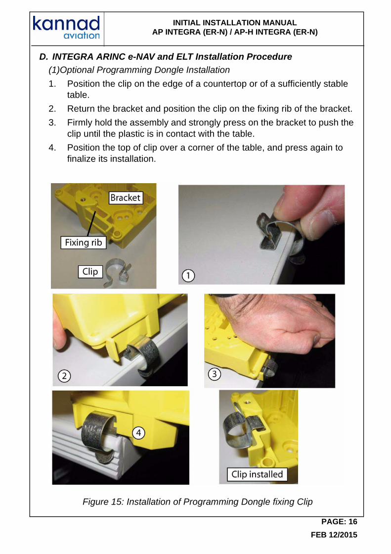
D. INTEGRA ARINC e-NAV and ELT Installation Procedure(1)Optional Programming Dongle Installation
1. Position the clip on the edge of a countertop or of a sufficiently stable table.
2. Return the bracket and position the clip on the fixing rib of the bracket.
3. Firmly hold the assembly and strongly press on the bracket to push the clip until the plastic is in contact with the table.
4. Position the top of clip over a corner of the table, and press again to finalize its installation.
Figure 15: Installation of Programming Dongle fixing Clip
PAGE: 16
FEB 12/2015
INITIAL INSTALLATION MANUAL AP INTEGRA (ER-N) / AP-H INTEGRA (ER-N)
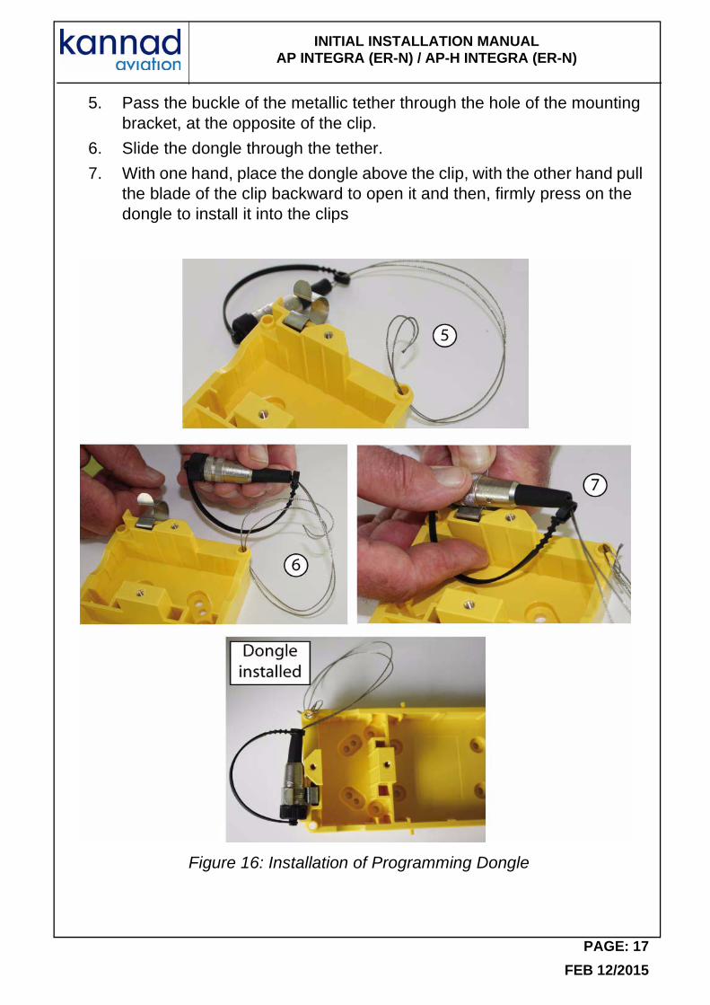
5. Pass the buckle of the metallic tether through the hole of the mounting bracket, at the opposite of the clip.
6. Slide the dongle through the tether.
7. With one hand, place the dongle above the clip, with the other hand pull the blade of the clip backward to open it and then, firmly press on the dongle to install it into the clips
Figure 16: Installation of Programming Dongle
PAGE: 17
FEB 12/2015
INITIAL INSTALLATION MANUAL AP INTEGRA (ER-N) / AP-H INTEGRA (ER-N)
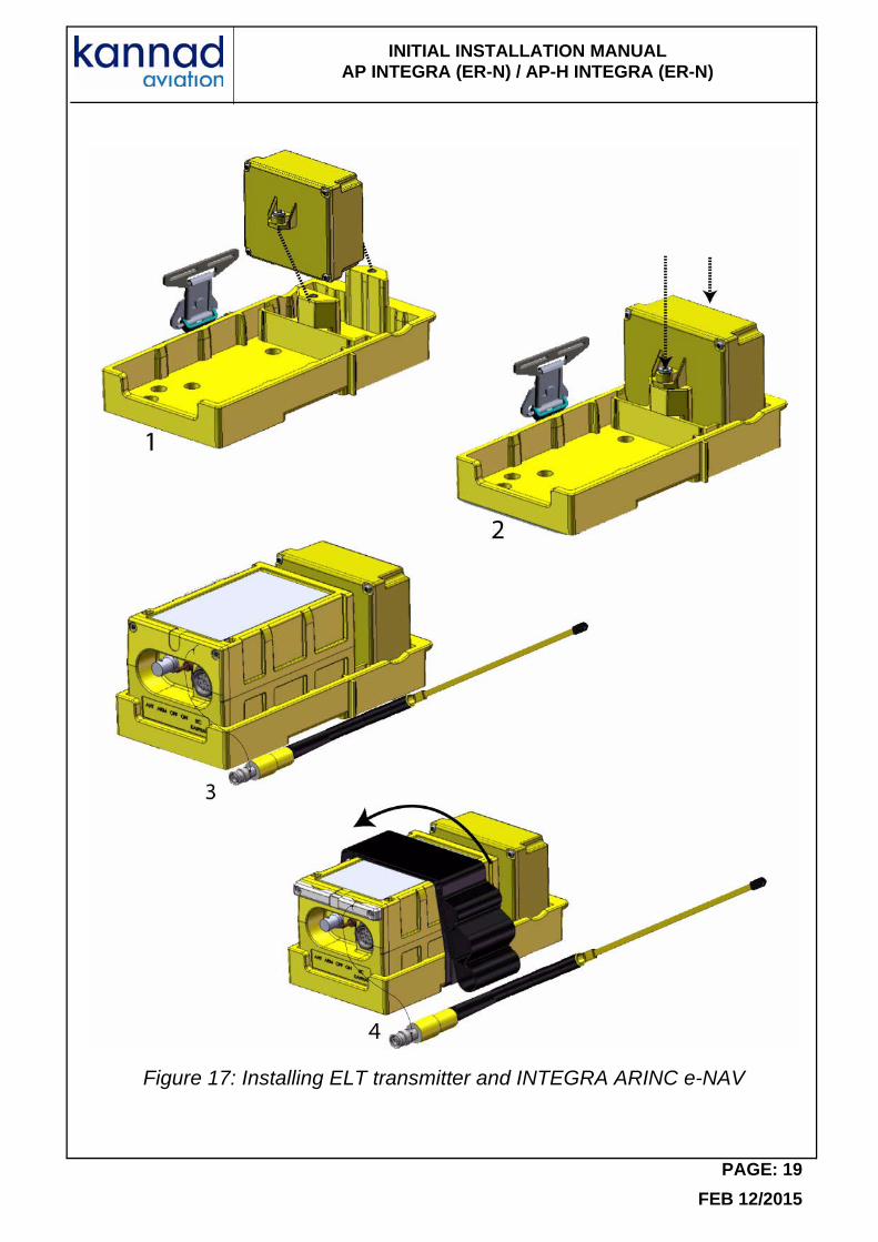
(2) ELT Installation
Refer to Figure 17: Installing ELT transmitter and INTEGRA ARINC e-NAV page 19
1. On the mounting bracket, place INTEGRA ARINC e-NAV housing onto its supports either with its connector on the left side or on the right side.
2. Fix the INTEGRA ARINC e-NAV onto the mounting bracket with the 2 captive screws and tighten to a torque of 1.4 Newton per meter using a torque driver with a 2.5 mm Allen bit.
3. Place the INTEGRA (ER-N) ELT onto the Bracket with "Flight Direction Arrow" of the ELT pointed towards the front of the aircraft.
• For AP INTEGRA (ER-N), refer to Figure 12: KANNAD AP INTEGRA, axis of installation page 12.
• For AP-H INTEGRA (ER-N) refer to Figure 13: KANNAD AP-H INTEGRA, axis of installation page 14.
4. Pass the attaching strap with the buckle above the ELT.
PAGE: 18
FEB 12/2015
INITIAL INSTALLATION MANUAL AP INTEGRA (ER-N) / AP-H INTEGRA (ER-N)
Figure 17: Installing ELT transmitter and INTEGRA ARINC e-NAV
PAGE: 19
FEB 12/2015
INITIAL INSTALLATION MANUAL AP INTEGRA (ER-N) / AP-H INTEGRA (ER-N)
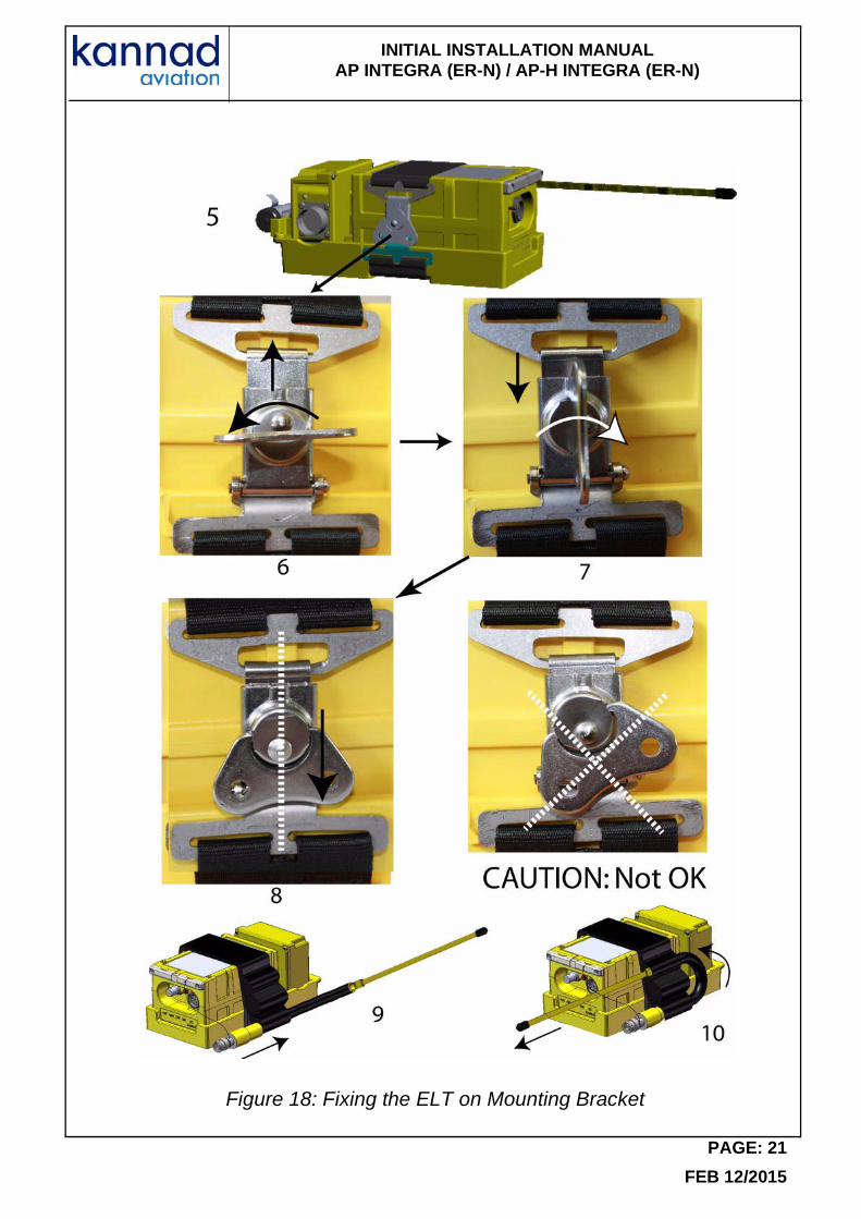
(3) ELT Fixing
Refer to Figure 18: Fixing the ELT on Mounting Bracket page 21
5. Fix the strap of the mounting bracket by locking the latch on the buckle of the strap.
6. Do a quarter turn counterclockwise to the latch then bring the hook of the latch onto the buckle of the attaching strap.
7. Do a quarter turn clockwise to the latch to fix the attaching strap by sliding the hook down.
8. Pull down the latch to lock the attaching strap.CAUTION: When locked, the center of the latch shall be aligned with the center of the buckle.
Check that the ELT is firmly attached:
IMPORTANT:
Once installed in the mounting bracket, the installer must be sure that the transmitter is firmly attached in its bracket by trying to extract it manually, thereby verifying there is no play and that it remains attached when extraction from the bracket is attempted.
CAUTION:
AN INCORRECT LOCKING OF THE LATCH COULD LEAD TO AN UNSAFE SITUATION BY THE ELT PREVENTING THE TRANSMISSION OF THE DISTRESS MESSAGE.
9. Slide the auxiliary antenna (extremity first) into the lower antenna housing of the attaching straps. Only the TNC connector shall be visible from this antenna housing.
10. Bent the antenna, then slide the extremity of the antenna into the upper antenna housing of the attaching straps.
PAGE: 20
FEB 12/2015
INITIAL INSTALLATION MANUAL AP INTEGRA (ER-N) / AP-H INTEGRA (ER-N)
Figure 18: Fixing the ELT on Mounting Bracket
PAGE: 21
FEB 12/2015
INITIAL INSTALLATION MANUAL AP INTEGRA (ER-N) / AP-H INTEGRA (ER-N)
5. External Antenna Installation
Use only whip, rod or blade approved antennas.
A. Antenna Installation Recommendations(1)FAA Recommendations
Installation must be made by qualified personnel in accordance with FAA regulations. Duplicating a previous installation may not be acceptable. Methods for installing antenna are outlined in AC43.13-12, refer to:
FAA - Advisory Circular 43.13-2B (Acceptable Methods, Techniques, and Practices - Aircraft Alterations), specifically, Chapters 1, 3, 11 and 13.
(2) RTCA DO-204 Recommendations for external antenna location
"ELT antennas should be located away from other antennas to avoid disruption of antenna radiation patterns."
"Idealistically, for the 121.5 MHz ELT antenna, 2.5 meter separation is sufficient separation from VHF communications and navigation receiving antennas to minimize unwanted interferences."
"ELT antennas should be vertically polarized when the aircraft is in the normal flight attitude."
"ELT antenna mounting surface should be able to withstand a static load equal to 100 times the antenna weight applied at the antenna mounting base in all directions."
"The antenna should be mounted as close to the respective ELT as applicable. The proximity of the ELT antenna to any vertically-polarized communications antenna shall be such as to minimize radio frequency interference and radiation pattern distortion of either antenna. Coaxial cable connecting the ELT antenna installation should not cross the aircraft production breaks and should have vibrations proof RF connectors on each end. The coaxial connecting the ELT transmitter to the external Antenna should be secured to the aircraft structure and when the coaxial cable is installed and the connectors are mated, each end should be have some slack."
(3) External Antenna Location
EUROCAE ED62A § 6.1.10.2
"The most effective antenna configuration for typical high-wing and low-wing aircraft is an external antenna, on top of the fuselage, and aft of the wing (high-wing), or near the vertical stabilizer (low-wing). Both ELT antennas should be located away from other antennas to avoid disruption
PAGE: 22
FEB 12/2015
INITIAL INSTALLATION MANUAL AP INTEGRA (ER-N) / AP-H INTEGRA (ER-N)
of antenna radiation patterns. Detuning of the 121.5 MHz antenna may be required avoid the effects of radiated inter-modulation products which may be possible from non-operating 121.5 MHz ELTs exposed to high levels of RF energy.
Idealistically, for the 121.5 MHz ELT antenna, 2.5 meter separation is sufficient separation from VHF communications and navigation receiving antennas to minimize unwanted interference. The 406 MHz ELT antenna should be positioned at least 0.8 m from VHF communications and navigation receiving antennas to minimize interference.
External antennas, which have been shown to be compatible with particular ELT will either be part of the ETSO/TSO's ELT or will be identified in the ELT manufacturer's installation instructions. Recommended methods for installing antenna are outlined in FAA AC 43.13-2B. The Antenna should be mounted as close to the respective ELT as practicable."
B. Antenna installation procedure
The antenna must be mounted on the top of the aircraft to assure maximum visibility of satellites. The upper aft portion of the fuselage should be preferred. It should be mounted away from projections such as a propeller, tail surfaces, or the shadow of large antennas. It is the responsibility of the installation agency to determine the appropriate and adequate antenna installation.
Locate a position on the fuselage according to Section (2) RTCA DO-204 Recommendations for external antenna location, page 22:
A double plate may be necessary for the antenna to meet rigidity specifications in Section (2) RTCA DO-204 Recommendations for external antenna location, page 22.
A 9 Kilogram force (20 pound force) applied in all direction should not cause an appreciable distortion in the aircraft skin.
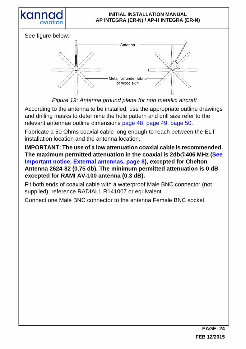
Each of the approved antennas requires a ground plane. On fabric-covered aircraft or aircraft with other types on nonmetallic skins, a ground plane must be added. This can be accomplished by providing a number of metal foil strips in a radial position from the antenna base and secured under the fabric or wood skin of the aircraft. The length of each foil radial should be at least equal to the antenna length and width at least 1 inch due to the diameter of the antenna. The ground plane must be connected to the shield of the antenna connector.
PAGE: 23
FEB 12/2015
INITIAL INSTALLATION MANUAL AP INTEGRA (ER-N) / AP-H INTEGRA (ER-N)
See figure below:
Figure 19: Antenna ground plane for non metallic aircraft
According to the antenna to be installed, use the appropriate outline drawings and drilling masks to determine the hole pattern and drill size refer to the relevant antennae outline dimensions page 48, page 49, page 50.
Fabricate a 50 Ohms coaxial cable long enough to reach between the ELT installation location and the antenna location.
IMPORTANT: The use of a low attenuation coaxial cable is recommended. The maximum permitted attenuation in the coaxial is 2db@406 MHz (See Important notice, External antennas, page 8), excepted for Chelton Antenna 2624-82 (0.75 db). The minimum permitted attenuation is 0 dB excepted for RAMI AV-100 antenna (0.3 dB).
Fit both ends of coaxial cable with a waterproof Male BNC connector (not supplied), reference RADIALL R141007 or equivalent.
Connect one Male BNC connector to the antenna Female BNC socket.
PAGE: 24
FEB 12/2015
INITIAL INSTALLATION MANUAL AP INTEGRA (ER-N) / AP-H INTEGRA (ER-N)
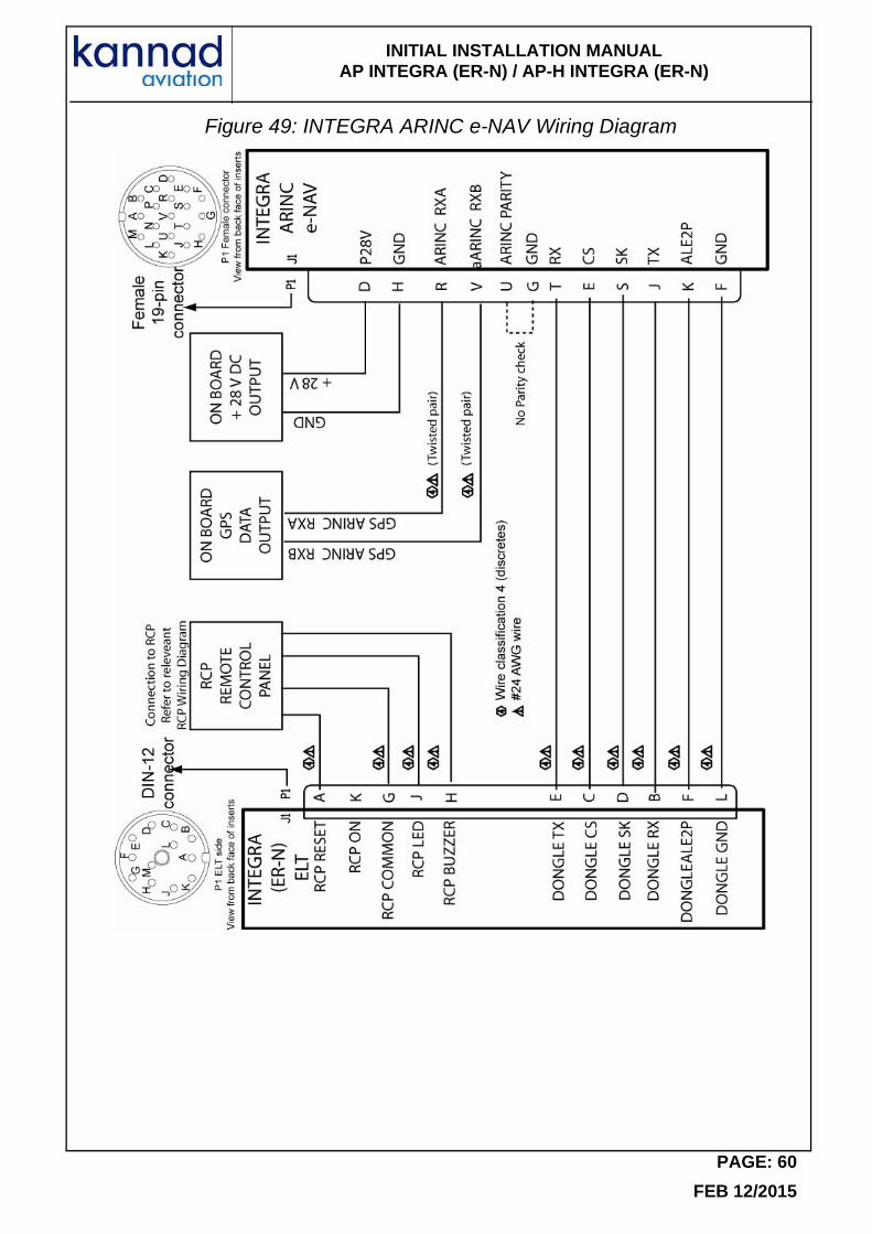
6. INTEGRA ARINC e-NAV, Connection to ELT
INTEGRA ARINC e-NAV must be connected to the ELT via a DIN-12 connector (P/N S1820514-03), on the ELT side and the relevant mating connector (19 Pin female connector reference SOURIAU 851 02 E14 19 S50) of the INTEGRA ARINC e-NAV on the INTEGRA ARINC e-NAV side.
Refer to Figure 49: INTEGRA ARINC e-NAV Wiring Diagram
Note: The DIN-12 connector is also used to connect the RCP to the ELT, see section 7 below.
7. RCP Installation
A. RCP Installation RecommendationsThe RCP shall be installed in the cockpit. The RCP shall be readily accessible from the pilot’s normal seated position.
B. RCP Installation Procedure
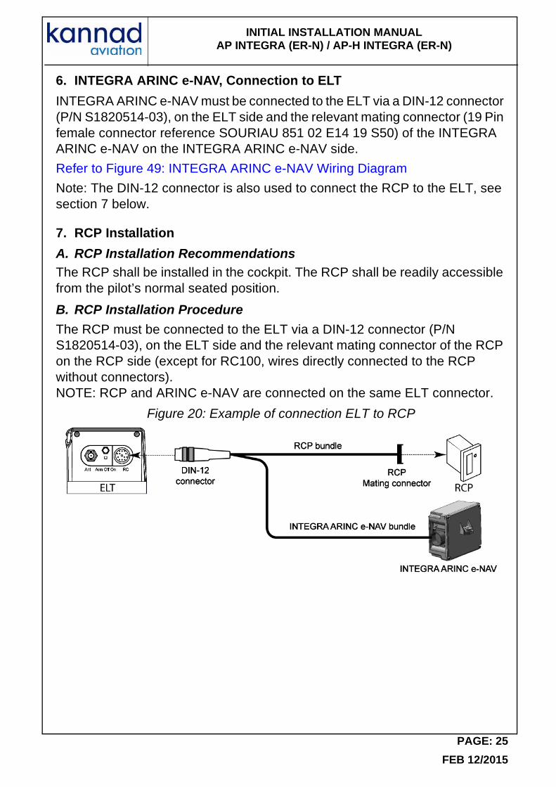
The RCP must be connected to the ELT via a DIN-12 connector (P/N S1820514-03), on the ELT side and the relevant mating connector of the RCP on the RCP side (except for RC100, wires directly connected to the RCP without connectors).NOTE: RCP and ARINC e-NAV are connected on the same ELT connector.
Figure 20: Example of connection ELT to RCP
PAGE: 25
FEB 12/2015
INITIAL INSTALLATION MANUAL AP INTEGRA (ER-N) / AP-H INTEGRA (ER-N)
(4) RC100
RC100 RCP is supplied as a kit (Refer to Figure 21: RC100 mounting diagram).
Connection of RC100 requires a 3-wire bundle or 5-wire bundle if an outside buzzer is connected. A pin-to-pin wiring has to be provided by the installer with AWG24 wires. Shielded wires are recommended.
The wires are soldered to the switch pins, a resistor and LED pins. This operation can be carried out before installation.
On the ELT side, the wires are soldered to a standard "DIN12 connector" (P/N S1820514-03).
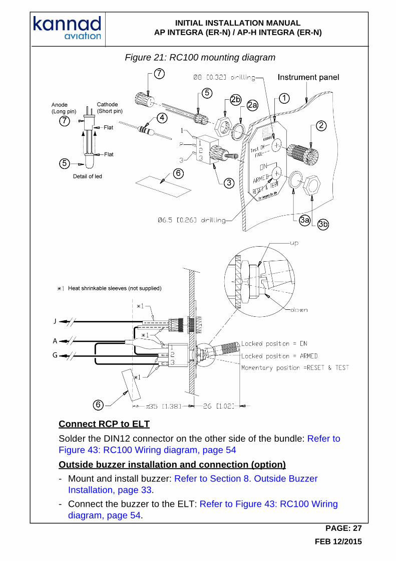
Mount and install RCPRefer to Figure 21: RC100 mounting diagram
NOTE: Pins of LED, pins of switch and resistor must be protected by heat shrinkable sleeves.
- Place the front plate (1) on the instrument panel;
- Trace the centers of the two holes according to drilling mask supplied;
- Drill a hole Ø 8 mm for the LED mounting (2) (top of the panel);
- Drill a hole Ø6.5 mm for the switch (3) (bottom of the panel);
- Tear off protection from self-adhesive film;
- Stick the front plate (1) on the instrument panel;
- Install the LED mounting (2), with washer (2a) and nut (2b). Tighten nut;
- Solder the resistor (4) to pin 1 of Switch (3);
- Connect the anode (long pin) of LED (5) to pin 2 of switch (3);
- Make a strap between pin 3 of switch (3) and resistor (4);
- Connect wires to pin 2 of switch (3), the resistor (4) and the cathode (short pin) of LED (5);
- Stuck the "identification label" (6) on the cable bundle near the switch;
- Insert the LED into the LED stand (7) taking care the flat part of the LED be in front of the flat part of the LED stand;
- Insert LED (5) fitted with LED stand (7) inside the LED mounting (2);
- Install the switch (3) with washer (3a) and nut (3b), locked position upwards. Tighten nut.
PAGE: 26
FEB 12/2015
INITIAL INSTALLATION MANUAL AP INTEGRA (ER-N) / AP-H INTEGRA (ER-N)
Figure 21: RC100 mounting diagram
Connect RCP to ELT
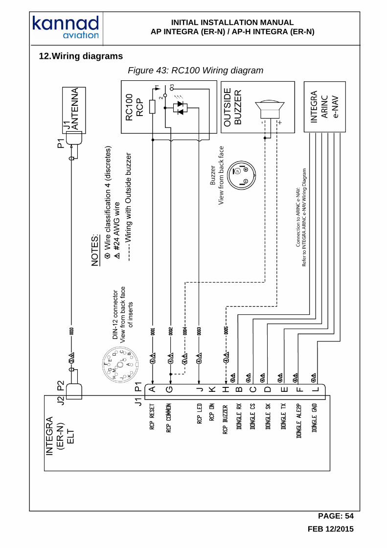
Solder the DIN12 connector on the other side of the bundle: Refer to Figure 43: RC100 Wiring diagram, page 54
Outside buzzer installation and connection (option)
- Mount and install buzzer: Refer to Section 8. Outside Buzzer Installation, page 33.
- Connect the buzzer to the ELT: Refer to Figure 43: RC100 Wiring diagram, page 54.
PAGE: 27
FEB 12/2015
INITIAL INSTALLATION MANUAL AP INTEGRA (ER-N) / AP-H INTEGRA (ER-N)
(5) RC200
The RC200 RCP is designed to be installed:
- either on the instrument panel with 4 screws (rivets bush recommended, not supplied);
- or below the instrument panel with a special mounting tray (supplied).
Installation on the instrument panel
- Determine RC200 location on the instrument panel:
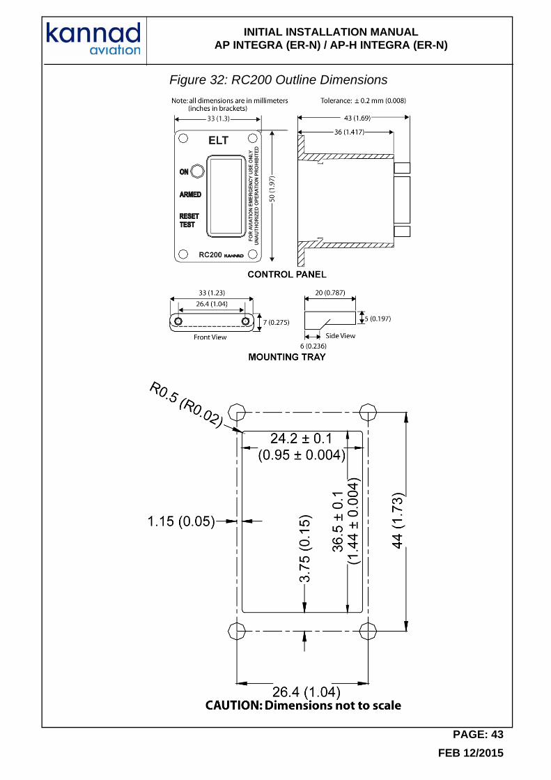
- Make a cutout on the instrument panel according to the Drilling mask (Refer to RC200 Outline Dimensions, page 43).
- Mark the 4 holes needed for the RC200 using the drilling mask or the RC200 as a guide.
- Drill the 4 marked holes, diameter depending on rivets bush used.
- Install the RC200 by fitting it into the cutout.
- Secure the RC200 (4 rivets bush recommended).Note: Rivets bush are not supplied.
Installation below the instrument panel
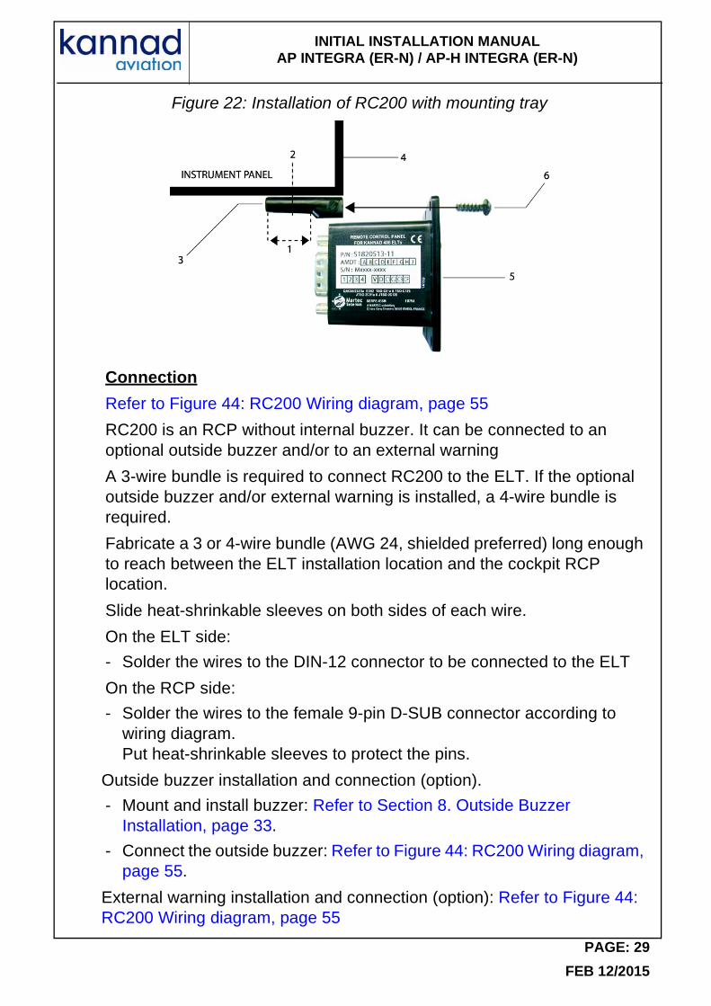
Refer to Figure 22: Installation of RC200 with mounting tray.
Determine RC200 location below the instrument panel (be sure the location meets the requirements established in RTCA-DO-204).
- According to the "area to be drilled" (1) of the mounting tray (3), determine the location of the screws or rivets (2) used to secure the mounting tray (3) to the instrument panel (4).
- Drill 2 holes on the mounting tray and on the instrument panel, diameter depending on screws or rivets used.
- Secure the mounting tray (3) to the instrument panel (4).
- Secure the RC200 (5) to the mounting tray (3) with the 2 screws (6) supplied (torque 0.8 Nm).
PAGE: 28
FEB 12/2015
INITIAL INSTALLATION MANUAL AP INTEGRA (ER-N) / AP-H INTEGRA (ER-N)
Figure 22: Installation of RC200 with mounting tray
Connection
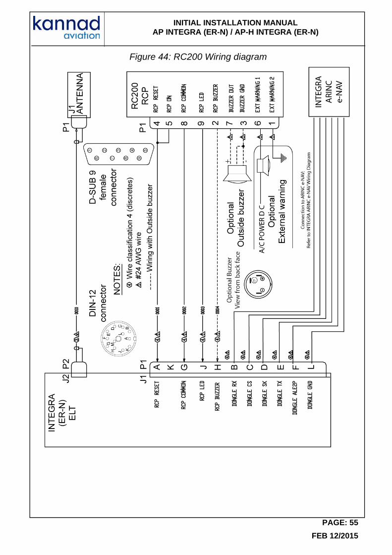
Refer to Figure 44: RC200 Wiring diagram, page 55
RC200 is an RCP without internal buzzer. It can be connected to an optional outside buzzer and/or to an external warning
A 3-wire bundle is required to connect RC200 to the ELT. If the optional outside buzzer and/or external warning is installed, a 4-wire bundle is required.
Fabricate a 3 or 4-wire bundle (AWG 24, shielded preferred) long enough to reach between the ELT installation location and the cockpit RCP location.
Slide heat-shrinkable sleeves on both sides of each wire.
On the ELT side:
- Solder the wires to the DIN-12 connector to be connected to the ELT
On the RCP side:
- Solder the wires to the female 9-pin D-SUB connector according to wiring diagram.Put heat-shrinkable sleeves to protect the pins.
Outside buzzer installation and connection (option).
- Mount and install buzzer: Refer to Section 8. Outside Buzzer Installation, page 33.
- Connect the outside buzzer: Refer to Figure 44: RC200 Wiring diagram, page 55.
External warning installation and connection (option): Refer to Figure 44: RC200 Wiring diagram, page 55
PAGE: 29
FEB 12/2015

INITIAL INSTALLATION MANUAL AP INTEGRA (ER-N) / AP-H INTEGRA (ER-N)
Connect the female 9-pin D-SUB connector to the male 9-pin D-SUB plug of the RC200.
(6) RC300 / RC300-NVG
Installation
The RC300 RCP is designed to be installed in a standard rack of an aircraft cockpit. As compliant with NF L 65-211 standard, no drilling is necessary to install this RCP.The precise location of RC300 is to be determined according to aircraft manufacturer instruction.
A male 9-pin D-SUB connector, reference AMPHENOL 17DE09PTZ or equivalent, must be used as mating connector to connect the bundle to the RCP connector.
Connection
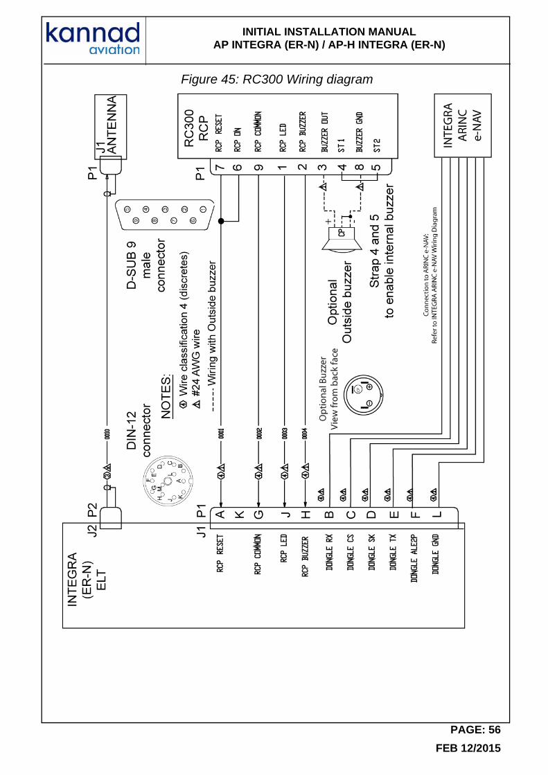
Refer to Figure 45: RC300 Wiring diagram, page 56
Fabricate a 4-wire bundle (AWG 24, shielded preferred) long enough to reach between the ELT installation location and the cockpit panel RCP location. Slide heat-shrinkable sleeves on both sides of each wire.
On the ELT side:
- Solder the wires to the DIN-12 connector.
On the RCP side:
- Solder the wires to the male 9-pin D-SUB connector according to wiring diagram.
- If an optional outside buzzer is connected:
• Mount and install the buzzer: Refer to Section 8. Outside Buzzer Installation, page 33
• Connect the buzzer: Refer to Figure 45: RC300 Wiring diagram, page 56.Put heat-shrinkable sleeves to protect the pins.
- Connect the male 9-pin D-SUB connector to the female 9-pin D-SUB plug of RC300.
PAGE: 30
FEB 12/2015
INITIAL INSTALLATION MANUAL AP INTEGRA (ER-N) / AP-H INTEGRA (ER-N)
(7) RC310
RC310 is designed to be installed on the instrument panel with two screws, washers and nuts.
The following connections are required:
- A 4-wire bundle for connection with the ELT. A pin-to-pin wiring has to be provided by the installer with AWG24 wires. Shielded cable is recommended.
- 2 wires for NVG function.
- 2 wires for Dimming function.
Installation
-Determine RC310 location on the instrument panel.
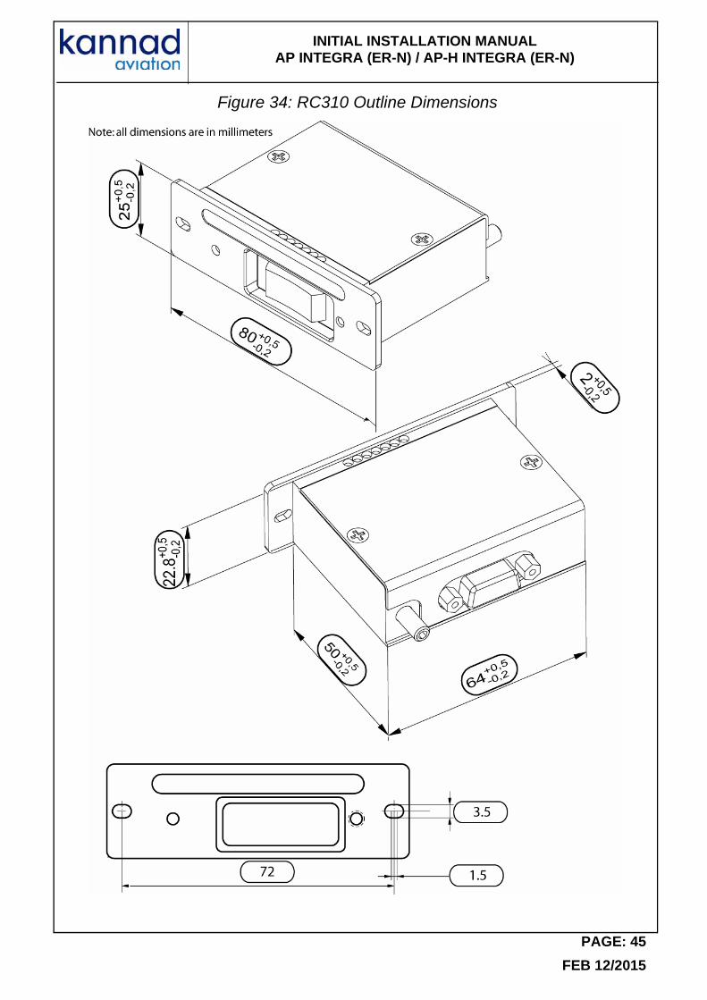
-Mark a cut out on the instrument panel according to the outline dimensions (Refer to Figure 34: RC310 Outline Dimensions, page 45).
- Make the cut out.
- Mark the 2 holes needed for RC310 using the front panel as a guide.
- Drill the 2 marked holes, diameter depending on screws used (see Note below).
- Instal RC310 by fitting into the cut out.
- Secure RC310 using two screws, washers and nuts.
Note: M3 screws LN9439, M3 washers LN9016 and anchor nuts with self-locking threads LN29671 are recommended.
Connection
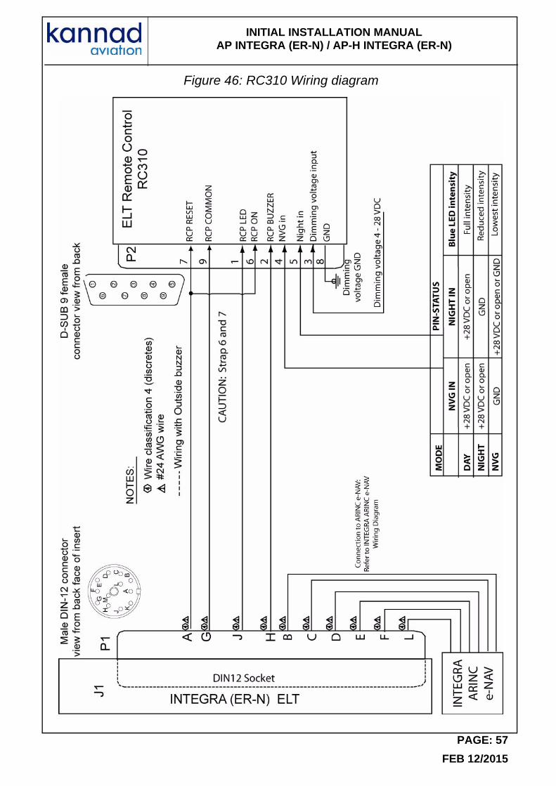
Refer to Figure 46: RC310 Wiring diagram, page 57
Fabricate a 4-wire bundle (AWG 24, shielded preferred) long enough to reach between the ELT installation location and the cockpit panel RCP location. Slide heat-shrinkable sleeves on both sides of each wire.
On the ELT side:
- Solder the wires to the DIN-12 connector.
On the RCP side:
- Solder the wires to the female 9-pin D-SUB connector according to wiring diagram.Put heat-shrinkable sleeves to protect the pins.
Connect the male 9-pin D-SUB connector to the female 9-pin D-SUB plug of RC300.
PAGE: 31
FEB 12/2015
INITIAL INSTALLATION MANUAL AP INTEGRA (ER-N) / AP-H INTEGRA (ER-N)
Backlight and night vision functions
For backlight and Night Vision functions, 4 wires shall be connected to the female D-SUB 9-Pin connector as follows:
- Slide heat-shrinkable sleeves on connector sides of each wire.
- Pin 3 has to be connected to Dimmfunction of aircraft.
- Pin 4 has to be connected to NVG in of aircraft.
- Pin 5 has to be connected to Night in of aircraft.
- Pin 8 has to be connected to GND Dimming voltage.
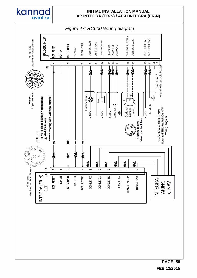
- Put heat-shrinkable sleeves to protect the pins.(8) RC600 NVG
Installation
The RC600 NVG RCP is designed to be installed in a standard rack of a military helicopter cockpit. As compliant with NF L 65-211 standard, no drilling is necessary to install this RCP.The precise location of RC600 is to be determined according to aircraft manufacturer instruction.
A female 22-pin socket, reference D38999/26JC35SA, must be used as mating connector to connect the bundle to the RCP connector.
Connection
Refer to Figure 47: RC600 Wiring diagram, page 58
Fabricate a 4-wire bundle (AWG 24, shielded preferred) long enough to reach between the ELT installation location and the cockpit panel RCP location. Slide heat-shrinkable sleeves on both sides of each wire.
On the ELT side:
- Solder the wires to the DIN-12 connector.
On the RCP side:
- Solder the wires to the female 22-pin socket according to wiring diagram.
- Connect Outside Lamp, Horn, Lamp test and Backlight.
- If an optional outside buzzer is connected:
• Mount and install the buzzer: Refer to Section 8. Outside Buzzer Installation, page 33
• Connect the buzzer: Refer to Figure 47: RC600 Wiring diagram, page 58.Put heat-shrinkable sleeves to protect the pins.
- Connect the female 22-pin socket to the male 22-pin plug of RC600.
PAGE: 32
FEB 12/2015
INITIAL INSTALLATION MANUAL AP INTEGRA (ER-N) / AP-H INTEGRA (ER-N)
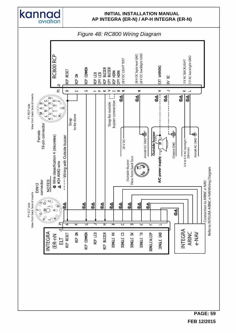
(9) RC800
Installation
RC800 is an RCP designed to be fixed with 2 DZUS locks on a standard mounting tray of the aircraft’s instrument panel. As compliant with NF L 65-211 standard, no drilling is necessary to install this RCP.The precise location of RC800 is to be determined according to aircraft manufacturer instruction.
A female 19-pin socket, reference HE301 B 06 E 14 19 S 1A, must be used as mating connector to connect the bundle to the RCP connector.
Connection
Refer to Figure 48: RC800 Wiring Diagram, page 59.
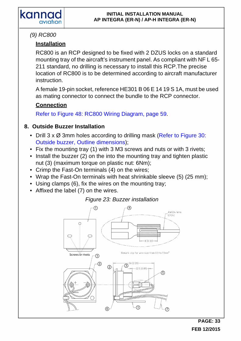
8. Outside Buzzer Installation
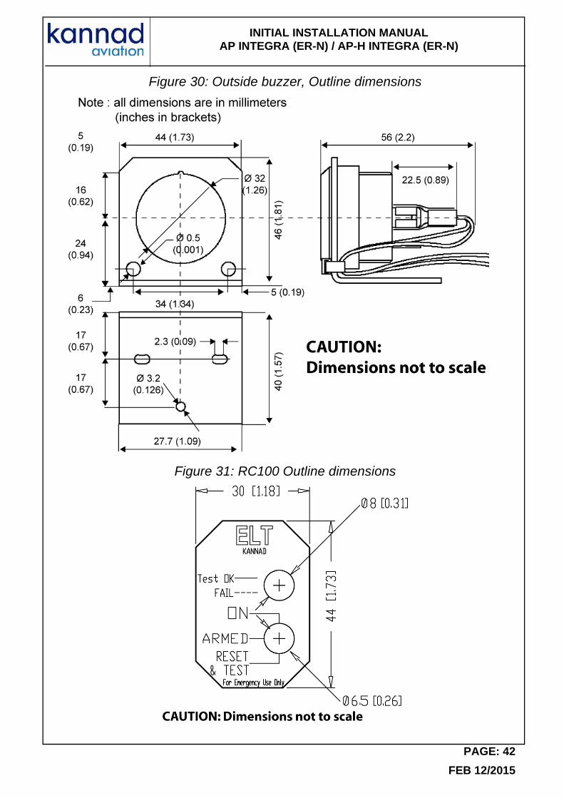
• Drill 3 x Ø 3mm holes according to drilling mask (Refer to Figure 30: Outside buzzer, Outline dimensions);
• Fix the mounting tray (1) with 3 M3 screws and nuts or with 3 rivets;• Install the buzzer (2) on the into the mounting tray and tighten plastic
nut (3) (maximum torque on plastic nut: 6Nm);• Crimp the Fast-On terminals (4) on the wires;• Wrap the Fast-On terminals with heat shrinkable sleeve (5) (25 mm);• Using clamps (6), fix the wires on the mounting tray;• Affixed the label (7) on the wires.
Figure 23: Buzzer installation
PAGE: 33
FEB 12/2015
INITIAL INSTALLATION MANUAL AP INTEGRA (ER-N) / AP-H INTEGRA (ER-N)
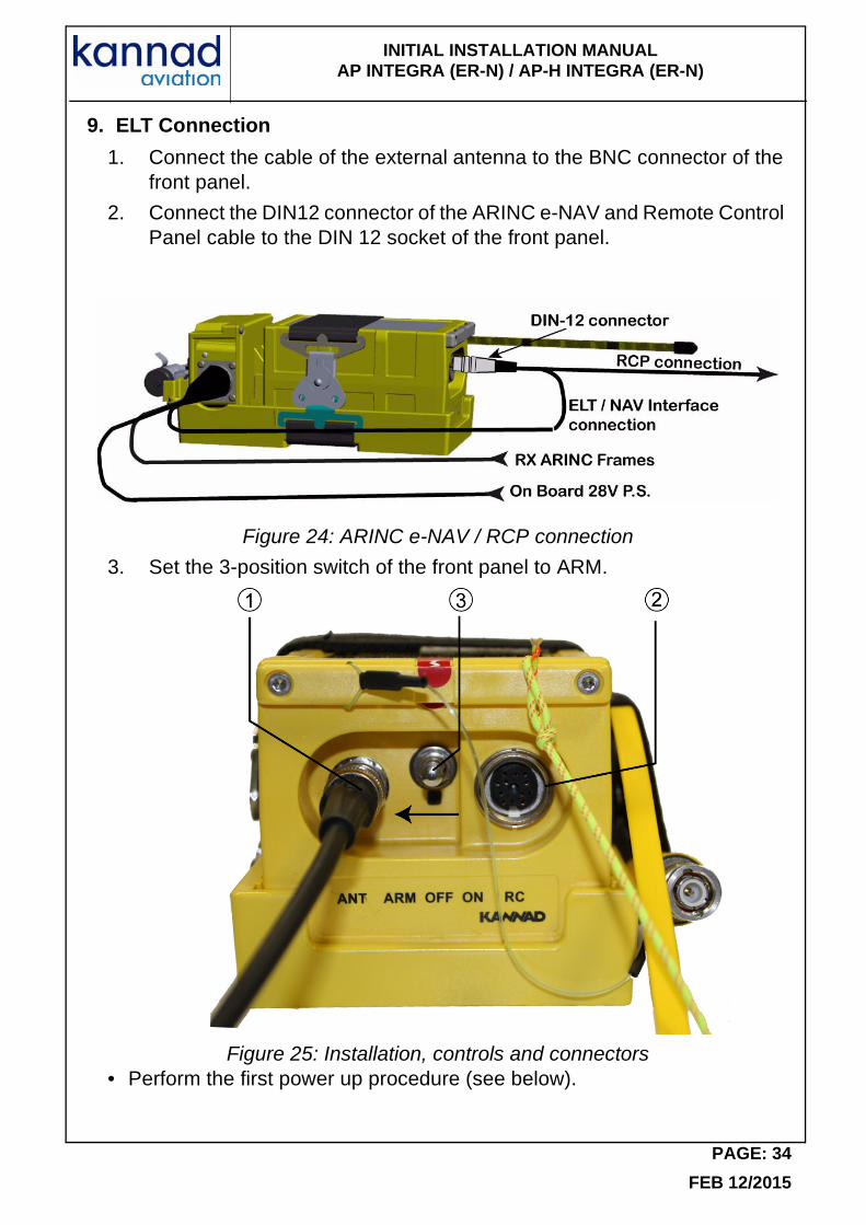
9. ELT Connection
1. Connect the cable of the external antenna to the BNC connector of the front panel.
2. Connect the DIN12 connector of the ARINC e-NAV and Remote Control Panel cable to the DIN 12 socket of the front panel.
Figure 24: ARINC e-NAV / RCP connection
3. Set the 3-position switch of the front panel to ARM.
Figure 25: Installation, controls and connectors• Perform the first power up procedure (see below).
PAGE: 34
FEB 12/2015
INITIAL INSTALLATION MANUAL AP INTEGRA (ER-N) / AP-H INTEGRA (ER-N)
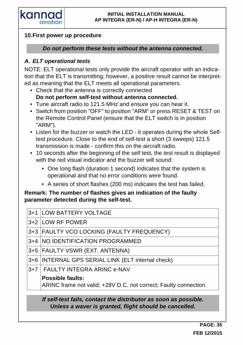
10.First power up procedure
A. ELT operational testsNOTE: ELT operational tests only provide the aircraft operator with an indica-tion that the ELT is transmitting; however, a positive result cannot be interpret-ed as meaning that the ELT meets all operational parameters.
• Check that the antenna is correctly connectedDo not perform self-test without antenna connected.
• Tune aircraft radio to 121.5 MHz and ensure you can hear it.• Switch from position "OFF" to position "ARM" or press RESET & TEST on
the Remote Control Panel (ensure that the ELT switch is in position "ARM").
• Listen for the buzzer or watch the LED - it operates during the whole Self-test procedure. Close to the end of self-test a short (3 sweeps) 121.5 transmission is made - confirm this on the aircraft radio.
• 10 seconds after the beginning of the self test, the test result is displayed with the red visual indicator and the buzzer will sound:
• One long flash (duration 1 second) indicates that the system is operational and that no error conditions were found.
• A series of short flashes (200 ms) indicates the test has failed.
Remark: The number of flashes gives an indication of the faulty parameter detected during the self-test.
Do not perform these tests without the antenna connected.
3+1 LOW BATTERY VOLTAGE
3+2 LOW RF POWER
3+3 FAULTY VCO LOCKING (FAULTY FREQUENCY)
3+4 NO IDENTIFICATION PROGRAMMED
3+5 FAULTY VSWR (EXT. ANTENNA)
3+6 INTERNAL GPS SERIAL LINK (ELT internal check)
3+7 FAULTY INTEGRA ARINC e-NAV
Possible faults:ARINC frame not valid; +28V D.C. not correct; Faulty connection.
If self-test fails, contact the distributor as soon as possible.Unless a waver is granted, flight should be cancelled.
PAGE: 35
FEB 12/2015
INITIAL INSTALLATION MANUAL AP INTEGRA (ER-N) / AP-H INTEGRA (ER-N)
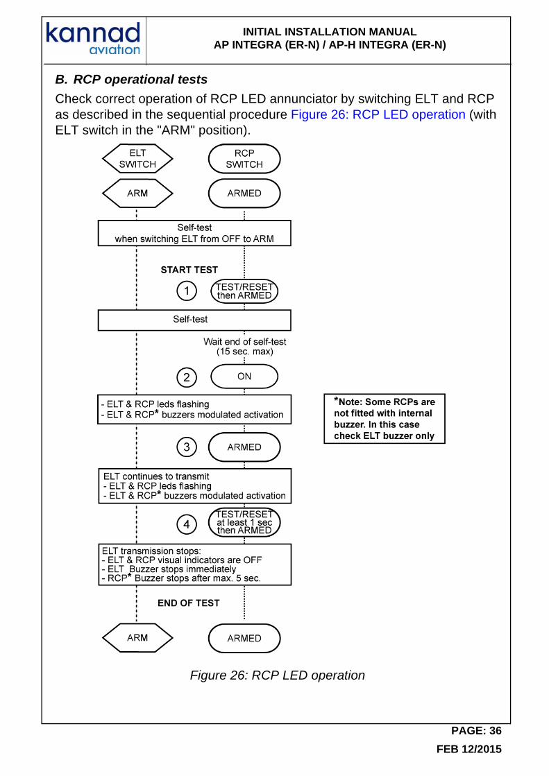
B. RCP operational tests
Check correct operation of RCP LED annunciator by switching ELT and RCP as described in the sequential procedure Figure 26: RCP LED operation (with ELT switch in the "ARM" position).
Figure 26: RCP LED operation
PAGE: 36
FEB 12/2015
INITIAL INSTALLATION MANUAL AP INTEGRA (ER-N) / AP-H INTEGRA (ER-N)
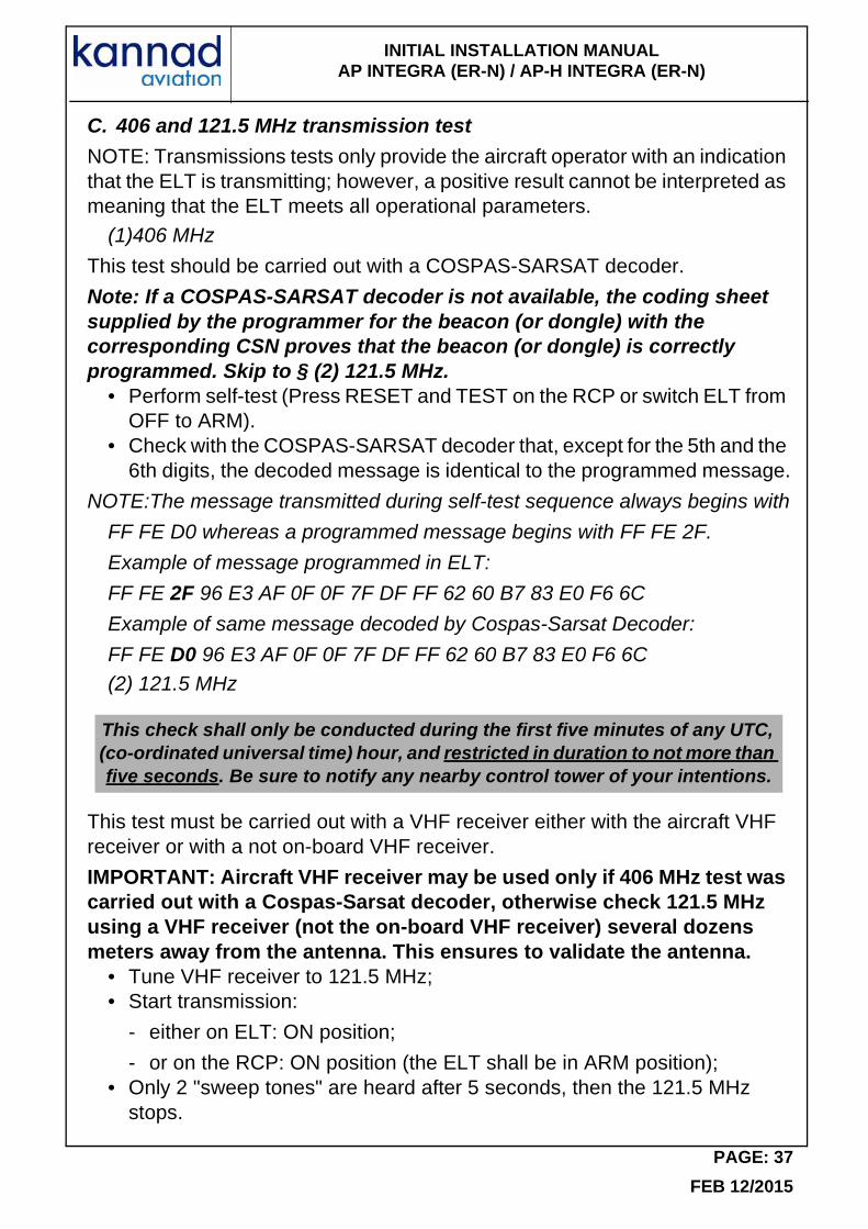
C. 406 and 121.5 MHz transmission test
NOTE: Transmissions tests only provide the aircraft operator with an indication that the ELT is transmitting; however, a positive result cannot be interpreted as meaning that the ELT meets all operational parameters.
(1)406 MHz
This test should be carried out with a COSPAS-SARSAT decoder.
Note: If a COSPAS-SARSAT decoder is not available, the coding sheet supplied by the programmer for the beacon (or dongle) with the corresponding CSN proves that the beacon (or dongle) is correctly programmed. Skip to § (2) 121.5 MHz.
• Perform self-test (Press RESET and TEST on the RCP or switch ELT from OFF to ARM).
• Check with the COSPAS-SARSAT decoder that, except for the 5th and the 6th digits, the decoded message is identical to the programmed message.
NOTE:The message transmitted during self-test sequence always begins with
FF FE D0 whereas a programmed message begins with FF FE 2F.
Example of message programmed in ELT:
FF FE 2F 96 E3 AF 0F 0F 7F DF FF 62 60 B7 83 E0 F6 6C
Example of same message decoded by Cospas-Sarsat Decoder:
FF FE D0 96 E3 AF 0F 0F 7F DF FF 62 60 B7 83 E0 F6 6C(2) 121.5 MHz
This test must be carried out with a VHF receiver either with the aircraft VHF receiver or with a not on-board VHF receiver.
IMPORTANT: Aircraft VHF receiver may be used only if 406 MHz test was carried out with a Cospas-Sarsat decoder, otherwise check 121.5 MHz using a VHF receiver (not the on-board VHF receiver) several dozens meters away from the antenna. This ensures to validate the antenna.
• Tune VHF receiver to 121.5 MHz;• Start transmission:
- either on ELT: ON position;
- or on the RCP: ON position (the ELT shall be in ARM position);• Only 2 "sweep tones" are heard after 5 seconds, then the 121.5 MHz
stops.
This check shall only be conducted during the first five minutes of any UTC, (co-ordinated universal time) hour, and restricted in duration to not more than five seconds. Be sure to notify any nearby control tower of your intentions.
PAGE: 37
FEB 12/2015

INITIAL INSTALLATION MANUAL AP INTEGRA (ER-N) / AP-H INTEGRA (ER-N)
• Stop transmission:
- either on ELT: OFF or ARM position;
- or on the Remote Control Panel: press TEST and RESET (the ELT shall be in ARM position).
- continue to listen to 121.5 MHz for a few seconds to ensure that the ELT does not continue to transmit after the test is terminated.
IMPORTANT: If the ELT operates for approximately 50 seconds, a 406 MHz signal is transmitted and is considered valid by the satellite system.
At the end of the first power up procedure, switch the ELT to ARM.
The ELT is now in stand by mode and ready to be activated:• either automatically by G-Switch sensor if a crash occurs;• or manually by Remote Control Panel.
Note: switching to ON directly on the ELT front panel will also activate the ELT.
PAGE: 38
FEB 12/2015
INITIAL INSTALLATION MANUAL AP INTEGRA (ER-N) / AP-H INTEGRA (ER-N)
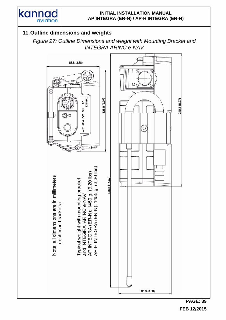
11.Outline dimensions and weights
Figure 27: Outline Dimensions and weight with Mounting Bracket and INTEGRA ARINC e-NAV
PAGE: 39
FEB 12/2015
INITIAL INSTALLATION MANUAL AP INTEGRA (ER-N) / AP-H INTEGRA (ER-N)
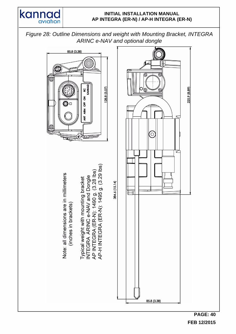
Figure 28: Outline Dimensions and weight with Mounting Bracket, INTEGRA ARINC e-NAV and optional dongle
PAGE: 40
FEB 12/2015
INITIAL INSTALLATION MANUAL AP INTEGRA (ER-N) / AP-H INTEGRA (ER-N)
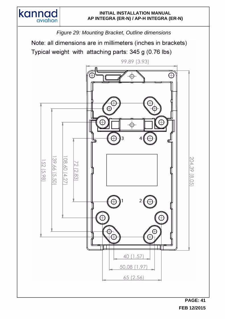
Figure 29: Mounting Bracket, Outline dimensions
PAGE: 41
FEB 12/2015
INITIAL INSTALLATION MANUAL AP INTEGRA (ER-N) / AP-H INTEGRA (ER-N)
Figure 30: Outside buzzer, Outline dimensions
Figure 31: RC100 Outline dimensions
PAGE: 42
FEB 12/2015
INITIAL INSTALLATION MANUAL AP INTEGRA (ER-N) / AP-H INTEGRA (ER-N)
Figure 32: RC200 Outline Dimensions
PAGE: 43
FEB 12/2015
INITIAL INSTALLATION MANUAL AP INTEGRA (ER-N) / AP-H INTEGRA (ER-N)
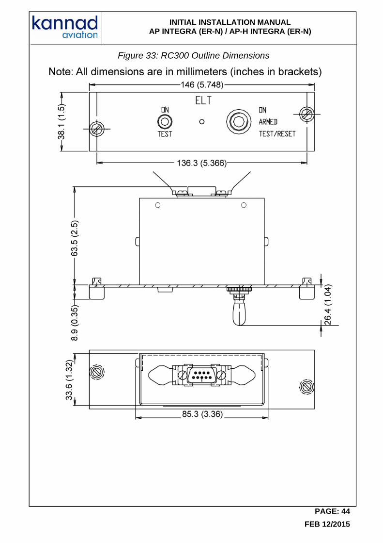
Figure 33: RC300 Outline Dimensions
PAGE: 44
FEB 12/2015
INITIAL INSTALLATION MANUAL AP INTEGRA (ER-N) / AP-H INTEGRA (ER-N)
Figure 34: RC310 Outline Dimensions
PAGE: 45
FEB 12/2015
INITIAL INSTALLATION MANUAL AP INTEGRA (ER-N) / AP-H INTEGRA (ER-N)
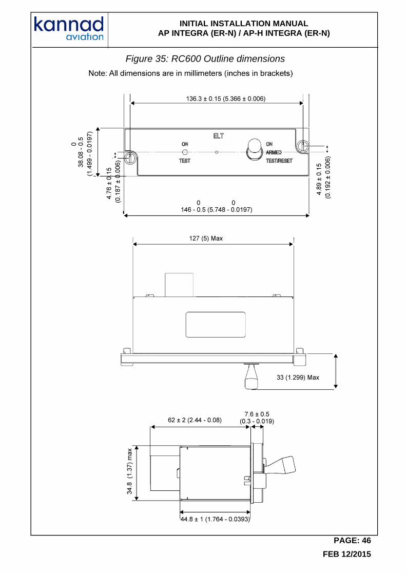
Figure 35: RC600 Outline dimensions
PAGE: 46
FEB 12/2015
INITIAL INSTALLATION MANUAL AP INTEGRA (ER-N) / AP-H INTEGRA (ER-N)
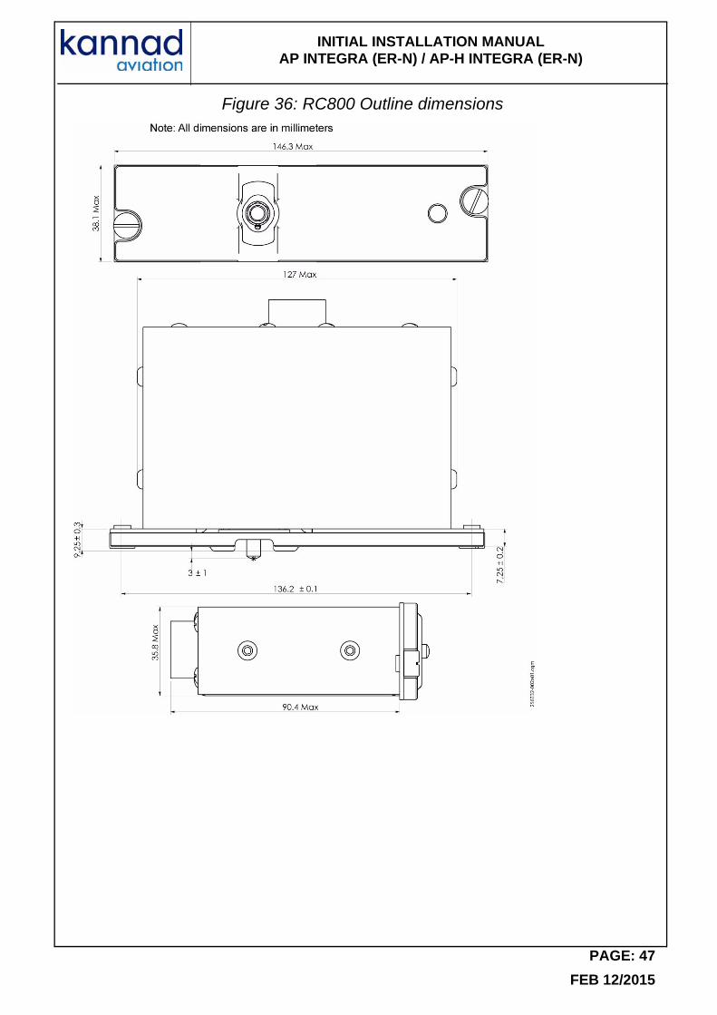
Figure 36: RC800 Outline dimensions
PAGE: 47
FEB 12/2015
INITIAL INSTALLATION MANUAL AP INTEGRA (ER-N) / AP-H INTEGRA (ER-N)
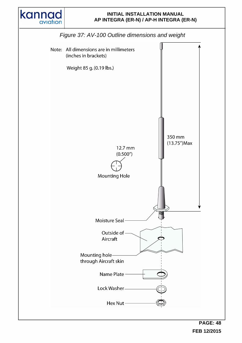
Figure 37: AV-100 Outline dimensions and weight
PAGE: 48
FEB 12/2015
INITIAL INSTALLATION MANUAL AP INTEGRA (ER-N) / AP-H INTEGRA (ER-N)
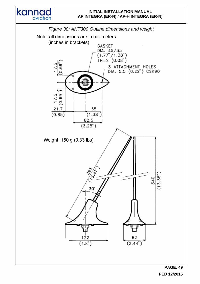
Figure 38: ANT300 Outline dimensions and weight
PAGE: 49
FEB 12/2015
INITIAL INSTALLATION MANUAL AP INTEGRA (ER-N) / AP-H INTEGRA (ER-N)
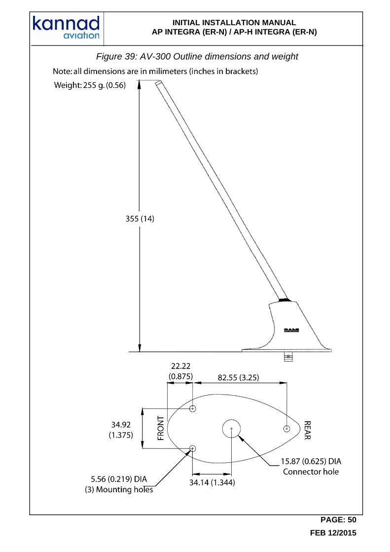
Figure 39: AV-300 Outline dimensions and weight
PAGE: 50
FEB 12/2015
INITIAL INSTALLATION MANUAL AP INTEGRA (ER-N) / AP-H INTEGRA (ER-N)
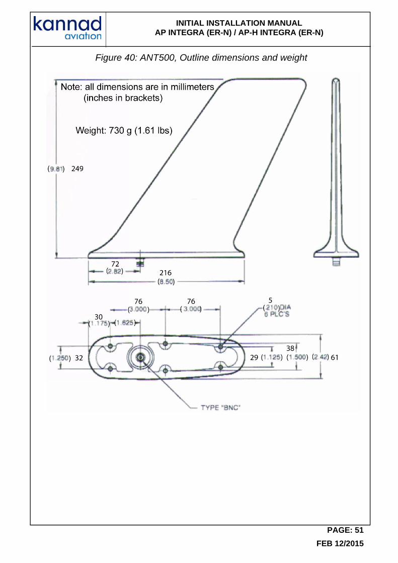
Figure 40: ANT500, Outline dimensions and weight
PAGE: 51
FEB 12/2015
INITIAL INSTALLATION MANUAL AP INTEGRA (ER-N) / AP-H INTEGRA (ER-N)
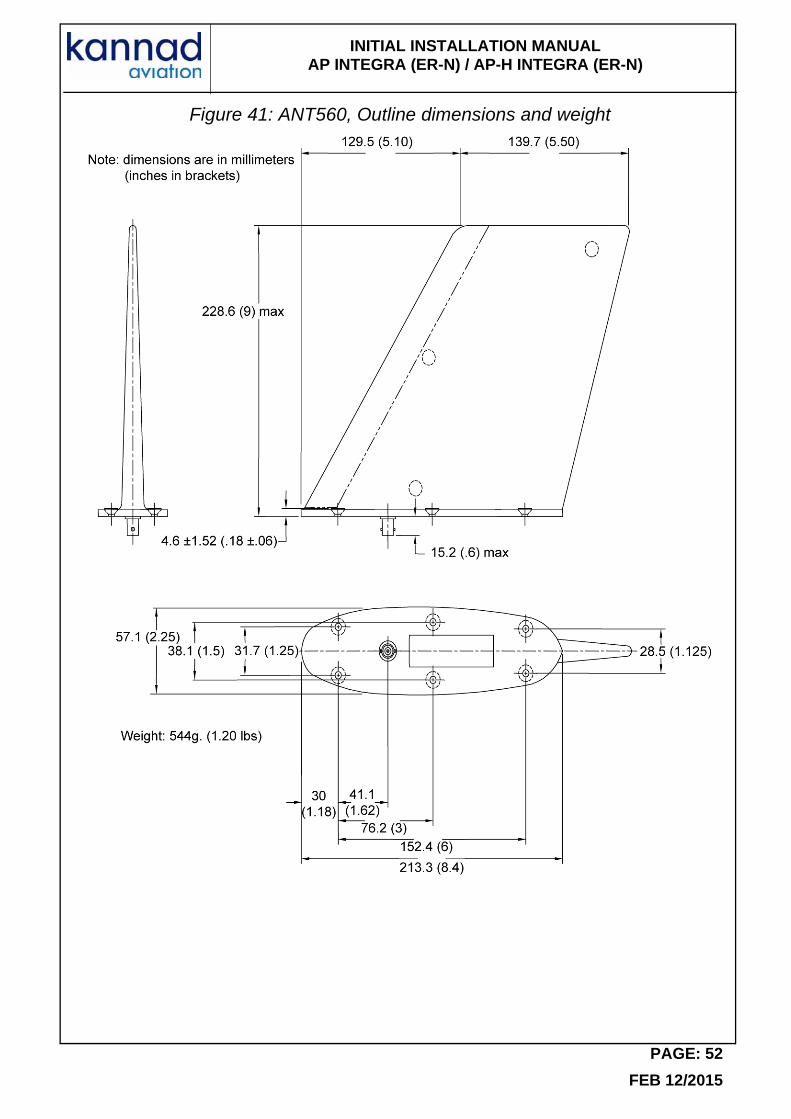
Figure 41: ANT560, Outline dimensions and weight
PAGE: 52
FEB 12/2015
INITIAL INSTALLATION MANUAL AP INTEGRA (ER-N) / AP-H INTEGRA (ER-N)
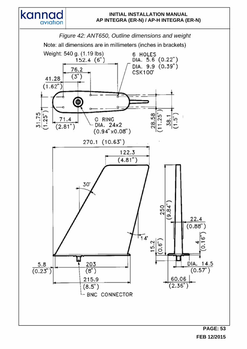
Figure 42: ANT650, Outline dimensions and weight
PAGE: 53
FEB 12/2015
INITIAL INSTALLATION MANUAL AP INTEGRA (ER-N) / AP-H INTEGRA (ER-N)
12.Wiring diagrams
Figure 43: RC100 Wiring diagram
PAGE: 54
FEB 12/2015
INITIAL INSTALLATION MANUAL AP INTEGRA (ER-N) / AP-H INTEGRA (ER-N)
Figure 44: RC200 Wiring diagram
PAGE: 55
FEB 12/2015
INITIAL INSTALLATION MANUAL AP INTEGRA (ER-N) / AP-H INTEGRA (ER-N)
Figure 45: RC300 Wiring diagram
PAGE: 56
FEB 12/2015
INITIAL INSTALLATION MANUAL AP INTEGRA (ER-N) / AP-H INTEGRA (ER-N)
Figure 46: RC310 Wiring diagram
PAGE: 57
FEB 12/2015
INITIAL INSTALLATION MANUAL AP INTEGRA (ER-N) / AP-H INTEGRA (ER-N)
Figure 47: RC600 Wiring diagram
PAGE: 58
FEB 12/2015
INITIAL INSTALLATION MANUAL AP INTEGRA (ER-N) / AP-H INTEGRA (ER-N)
Figure 48: RC800 Wiring Diagram
PAGE: 59
FEB 12/2015
INITIAL INSTALLATION MANUAL AP INTEGRA (ER-N) / AP-H INTEGRA (ER-N)
Figure 49: INTEGRA ARINC e-NAV Wiring Diagram
PAGE: 60
FEB 12/2015
INITIAL INSTALLATION MANUAL AP INTEGRA (ER-N) / AP-H INTEGRA (ER-N)
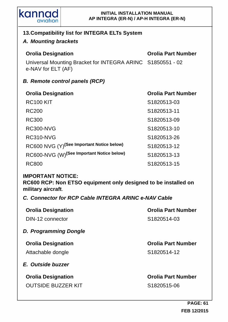
13.Compatibility list for INTEGRA ELTs System
A. Mounting brackets
B. Remote control panels (RCP)
IMPORTANT NOTICE:RC600 RCP: Non ETSO equipment only designed to be installed on military aircraft.
C. Connector for RCP Cable INTEGRA ARINC e-NAV Cable
D. Programming Dongle
E. Outside buzzer
Orolia Designation Orolia Part Number
Universal Mounting Bracket for INTEGRA ARINC e-NAV for ELT (AF)
S1850551 - 02
Orolia Designation Orolia Part Number
RC100 KIT S1820513-03
RC200 S1820513-11
RC300 S1820513-09
RC300-NVG S1820513-10
RC310-NVG S1820513-26
RC600 NVG (Y)(See Important Notice below) S1820513-12
RC600-NVG (W)(See Important Notice below) S1820513-13
RC800 S1820513-15
Orolia Designation Orolia Part Number
DIN-12 connector S1820514-03
Orolia Designation Orolia Part Number
Attachable dongle S1820514-12
Orolia Designation Orolia Part Number
OUTSIDE BUZZER KIT S1820515-06
PAGE: 61
FEB 12/2015
INITIAL INSTALLATION MANUAL AP INTEGRA (ER-N) / AP-H INTEGRA (ER-N)
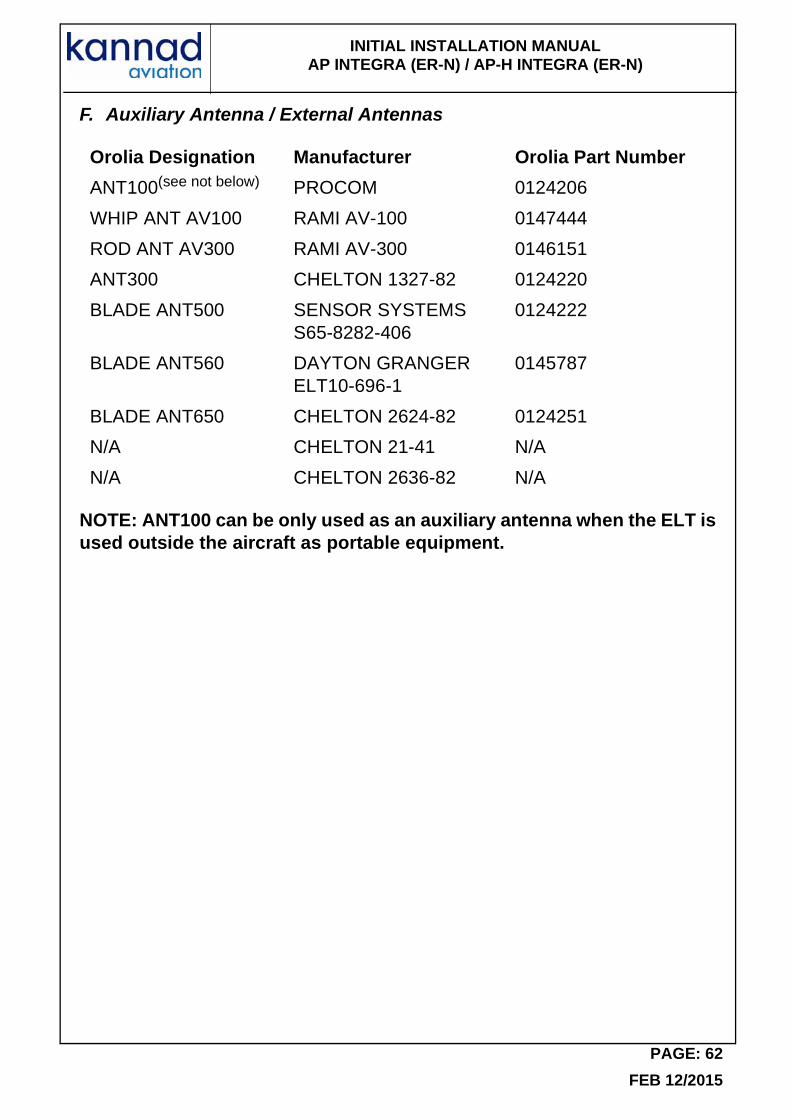
F. Auxiliary Antenna / External Antennas
NOTE: ANT100 can be only used as an auxiliary antenna when the ELT is used outside the aircraft as portable equipment.
Orolia Designation Manufacturer Orolia Part Number
ANT100(see not below) PROCOM 0124206
WHIP ANT AV100 RAMI AV-100 0147444
ROD ANT AV300 RAMI AV-300 0146151
ANT300 CHELTON 1327-82 0124220
BLADE ANT500 SENSOR SYSTEMS S65-8282-406
0124222
BLADE ANT560 DAYTON GRANGER ELT10-696-1
0145787
BLADE ANT650 CHELTON 2624-82 0124251
N/A CHELTON 21-41 N/A
N/A CHELTON 2636-82 N/A
PAGE: 62
FEB 12/2015


DOC14003DRef.: 0147630D
Distributed by
Manufactured by
Orolia S.A.S.
Z.I. des Cinq Chemins CS1002856520 GUIDEL - FRANCE
Phone: +33 (0) 2 97 02 49 49 Fax: +33 (0) 2 97 65 00 20
A Company of the McMurdo Group