insulation assessment -...
TRANSCRIPT

Insulation Assessment
by
Randy Keener
Torq Engineering Ltd.
Insulation assessment is one of the more complex issues in electrical predictive
maintenance. There are many different types of insulation systems found in rotating
equipment, transformers, switchgear, etc. There are many different diagnostic
technologies available. And there are many differences of opinion regarding what and
how to implement a testing program. But, insulation failures are common and are an
important part of any electrical condition monitoring or preventive maintenance program.
One way to categorize insulation assessment technologies is by nondestructive and
destructive techniques. A few insulation diagnostic technologies are considered to be
nondestructive. But, most are classified as destructive tests.
Predictive tests are those which help verify that an insulation system is likely to survive
for a significant period of time. Let me be clear. It is not presently possible to perform
thorough predictive tests on an insulation system without performing potentially
destructive tests. On-line and off-line tests which are performed at line voltage or below
do help assess the condition of an insulation system. But, there are numerous insulation
failure modes which cannot be detected without stressing the insulation above its
normal operating voltage.
Potentially destructive overvoltage tests are performed by manufacturers and as proof
tests after installation. Without them there is low confidence in an asset’s life
expectancy. Would you buy a motor or a transformer from a manufacturer who did not
perform overvoltage tests? Would you use a motor rewind shop which did not verify the
quality of the rewind with testing? Would you install a transmission line without
performing proof tests? Would you rely on fault protection equipment which was not
properly tested by the manufacturer?
A predictive maintenance professional has the same dilemma. To gain high confidence
in the longevity of an insulation system, it must be tested using over voltage tests.
It is common to hear statements like “High voltage testing damages insulation”. Or “I
don’t want to be blamed for causing a problem”.
The main question which must be answered when designing an insulation assessment
program for your assets is “What are the ramifications of unexpected insulation

failure?”. Then we can determine if a monitoring program is warranted and design it to
meet the need. When the cost of repairing or replacing a critical asset during an
unplanned outage is greater than the cost of repairing or replacing it during a planned
outage, that asset probably warrants predictive insulation testing.
Overvoltage predictive insulation testing reveals insulation which has significant
weakness and is likely to fail in the not too distant future. Still overvoltage testing is
different from many PdM technologies in that it is potentially destructive. The insulation
breakdown voltage often is usually lower after the weak insulation is detected than it
was before the test was performed.
There are a lot of different ways to test insulation. There are a lot of different
manufacturers of test equipment. Some overvoltage insulation tests are less destructive
than others. And even though they perform the same test, equipment from different
vendors may cause significantly different levels of damage when a fault is detected.
Later you will read about the use of partial discharge detection which allows overvoltage
testing to be performed with much less concern for causing damage to an insulation
system.
Still, a good rule of thumb is to perform overvoltage tests on critical assets only during a
planned outage when there is time to deal with the discovery of faulty insulation. Never
test when there is no time to remedy a problem you discover.
Insulation Resistance/Polarization Index Testing
The most common insulation test is the Insulation Resistance (IR) test. It may also be
called a Megger test. This test applies a DC high voltage between two conductors
separated by an insulating material. A very small current flows through and on the
surface of the insulator. The current is measured in micro-amps.
Recommended IR test voltages are typically greater than 500 VDC. In general, the IR
test is considered a nondestructive test since a DC power supply has low power and the
test is usually performed below line voltage. It is very possible for an insulation system
to pass an IR test and still have a serious flaw.
When the DC voltage is applied, there is initially a large capacitive charging current
which rapidly decays to zero. The remaining current which flows through the insulator is
called the absorption or resistive current. In the presence of the electric field, a solid
material’s dielectric dipoles slowly align causing some reduction in the resistive current
over time. In addition, there may be some current which flows on the surface of the
insulator. The total resistive current leakage is the sum of the absorption and surface
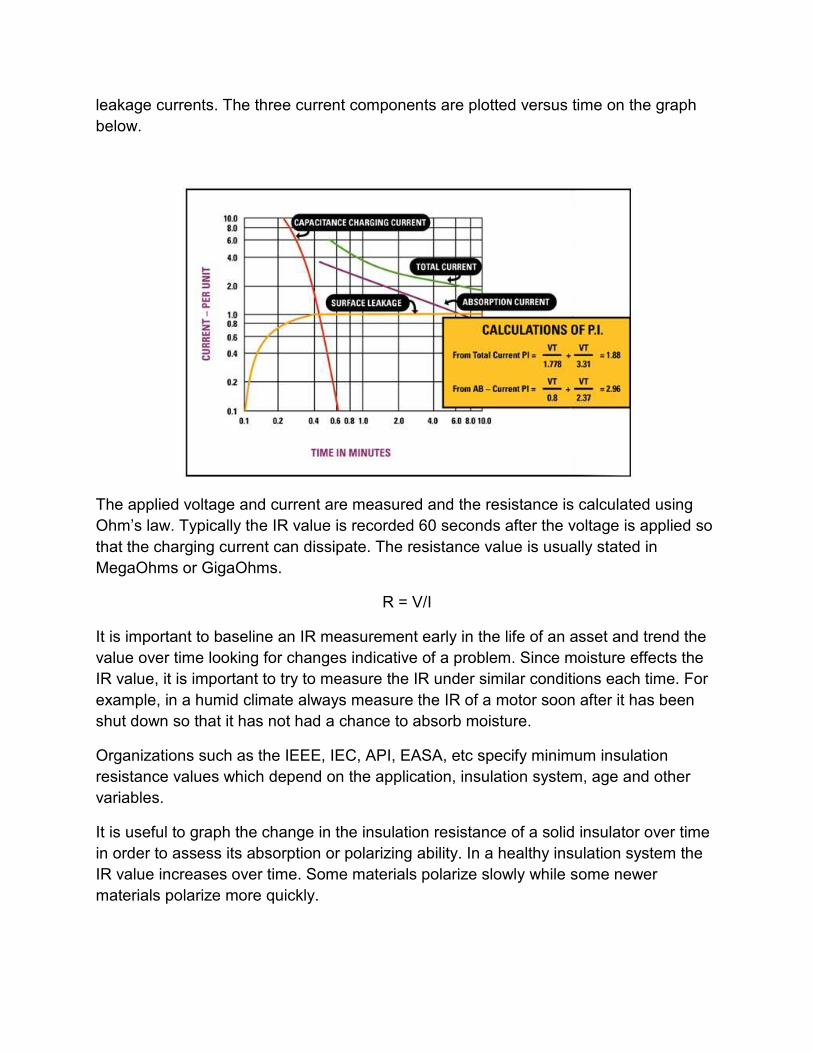
leakage currents. The three current components are plotted versus time on the graph
below.
The applied voltage and current are measured and the resistance is calculated using
Ohm’s law. Typically the IR value is recorded 60 seconds after the voltage is applied so
that the charging current can dissipate. The resistance value is usually stated in
MegaOhms or GigaOhms.
R = V/I
It is important to baseline an IR measurement early in the life of an asset and trend the
value over time looking for changes indicative of a problem. Since moisture effects the
IR value, it is important to try to measure the IR under similar conditions each time. For
example, in a humid climate always measure the IR of a motor soon after it has been
shut down so that it has not had a chance to absorb moisture.
Organizations such as the IEEE, IEC, API, EASA, etc specify minimum insulation
resistance values which depend on the application, insulation system, age and other
variables.
It is useful to graph the change in the insulation resistance of a solid insulator over time
in order to assess its absorption or polarizing ability. In a healthy insulation system the
IR value increases over time. Some materials polarize slowly while some newer
materials polarize more quickly.

A measure of the polarizing ability of insulation is called the Polarization Index (PI). PI is
a ratio of the IR value after the insulation is highly polarized divided by the initial IR
value. Usually the numerator is the IR value at 10 minutes.
PI = IR @ 10 min / IR @ 1 min
A minimum PI value of 1.5 or 2.0 is normally expected in a healthy solid insulation. In
the example shown below, the IR value at 1 minute is about 4,800 MegaOhms. The IR
value at 10 minutes is about 14,500 MegaOhms. So the PI ratio is about 3. It is helpful
to baseline the PI value early in the life of an asset and trend the PI over time looking for
changes indicative of a developing problem.
With very fast polarizing materials, the IR value at 1 minute may be similar to the 10
minute value resulting in a PI value which may seem low. IEEE 43 allows the tester to
choose times shorter than 1 and 10 minutes to achieve a PI ratio which more accurately
represents what is happening on the resistance versus time graph. A common
alternative is the 30 second/3 minute PI ratio.
PI = IR @ 3 min / IR @ 30 sec
If times other than 1 minute and 10 minutes are used, it is important to document and
always be consistent with the times for the IR and PI measurements.
IR and PI are measurements which quantify the bulk condition of an insulation system
which may be complex and made up of numerous components with various defects. It
will be necessary to isolate and test individual components if a weakness is detected. In
addition, IR and PI testing does not provide insight into the integrity of the insulation
between turns and phases in wound products such as motors, generators or
transformers.
The IR and PI tests may be used as a first step in ground insulation assessment. They
must be combined with other more conclusive insulation tests in a “predictive”
maintenance program.
The IR and PI tests are useful as a maintenance test for identifying:
• Moisture
• Surface contaminants
• Mechanical stress
• Aging and thermal damage
Electric Circuit Analysis
Electric Circuit Analysis tests are resistance, inductance and capacitance tests. They
are low voltage tests which identify insulation failures only after they are catastrophically
affecting the electrical system. It is a waste of effort to routinely perform ECA insulation
inspection tests on your assets. ECA tests are useful only as troubleshooting tools on
already failed assets.
Some maintenance professionals believe that ECA tests are more predictive than they
really are. It is a common false belief is that ECA can identify developing insulation
issues well before they affect the operation of the electrical system. Yet it is not
uncommon for a motor to pass the ECA tests even after it has already failed
catastrophically. Other times a motor will pass the ECA tests and then fail very soon
after testing. This happens because the operating voltage of the motor is much greater
than the test voltage of these tests. The motor has a short a line voltage, but, appears to
be okay when tested with a low voltage meter.
I regularly encounter PdMA and AllTest equipment users who believe they have a good
insulation testing program. The test equipment vendors are largely to blame because of
frequent misleading claims which defy the laws of physics. I have never talked to an
electrician who has predictively detected an insulation problem with an ECA tester. But,
I have talked with hundreds who have had motors fail very soon after ECA testing.
Low voltage ECA tests are not adequate for any kind of scheduled insulation inspection
program.

Overvoltage Hipot
Hipot is a very general term which is short for high potential or high voltage testing. The
term is used any time that a high voltage is applied between two conductors to assess
the insulation between the conductors. Usually Hipot refers to a test voltage which
exceeds the operating voltage of the equipment. Hipot test power supplies can be DC,
AC or impulse.
Historically, a Hipot is used to check for breakdown of an inadequate insulation system
by verifying that the current does not exceed a specification. Hipot tests are routinely
used by manufacturers and by installers who must verify the integrity of an insulation
system. When breakdown does not occur, a hipot test is not destructive. If breakdown
occurs, the Hipot test becomes destructive. Visible arcing occurs which damages the
insulation system. Some hipots cause much more damage than others.
Line Frequency AC Hipot
AC Hipot testing is an over voltage test performed at a frequency close to operating
frequency. In general, Hipot testing performed at frequencies of 20 – 300 Hz are
considered to be equivalent to line frequency tests. AC Hipot testing is a well
understood technology preferred by those who want to most closely replicate actual
operating conditions.
AC Hipot testing has traditionally been used for most manufacturer and installation proof
testing. Modern AC Hipot instruments usually incorporate capacitive compensation and
arc detection circuitry. The goal of capacitive compensation is to measure the resistive
part of the leakage current on a primarily capacitive load. The purpose of the arc
detection circuit is to detect small arcs which may not affect the measured total leakage
current and terminate the test in order thereby minimizing the damage caused.
AC Hipot is the most potentially destructive of all the Hipot tests because of the large
currents which severely damage insulation during breakdown. Because of the damage it
can cause, AC Hipot has limited application as a maintenance test. Most users prefer
alternatives.
With the advent of PD testing, it has become desirable to Hipot test with AC. Some
companies now promote AC testing for PdM applications. A drawback of AC testing is
the large size and cost of the HV power supplies required to test capacitive loads. They
can be semi tractor trailer sized. So alternatives to AC Hipots which enable PD
detection in PdM applications are being introduced. The tan delta value can be
measured during an AC Hipot test.

AC Hipot is used to detect:
• Insulation weakness between isolated conductors
• Moisture
• Surface contaminants
• Aging and thermal damage
DC Hipot
DC Hipot has long been the preferred test method for most maintenance applications.
Industry accepted DC test procedures are well defined for a wide variety of applications.
The standards generally require that a DC test should be performed at 1.7 times the
RMS voltage of the AC Hipot test. The 20% higher peak voltage is necessary to achieve
a comparable breakdown voltage.
DC Hipot testing employs the same techniques as the insulation resistance test except
that the test voltages are greater. DC is considered to be the least potentially
destructive of all the Hipot tests because of its relatively low current levels and the
rapidity of extinguishing a breakdown arc
There is one application where DC is no longer an accepted test methodology. DC
Hipot has been identified as causing damage in water-treed extruded Polyethelene
cables above 5 kV and is therefore discouraged by the IEEE, IEC and EPRI when
testing through cables.
DC Hipot testing is usually carried out by incrementally stepping or ramping from low
voltage to the target test voltage. As the voltage increases, the insulation resistance is
measured and evaluated. If the IR starts to increase nonlinearly or falls below a
specified limit, it is a sign of insulation weakness and the test is terminated hopefully
before breakdown occurs.
DC Hipot test equipment is relatively compact and light weight and it is easy to learn to
use. New DC Hipot testers are computer controlled and have solid-state power supplies
with a stable output voltage which allow them to be sensitive to small changes in IR. Dc
Hipot is used to detect:
• Insulation weakness between isolated conductors
• Moisture
• Surface contaminants
• Aging and thermal damage

The one major disadvantage of DC Hipot testing is that it cannot be used in conjunction
with partial discharge (PD) detectors. DC voltage does not generate PD. In applications
where PD detection is important, DC Hipot testing is no longer the preferred predictive
test method.
Very Low Frequency AC Hipot
Very Low Frequency (VLF) Hipot is an over voltage AC test performed at frequencies
between 0.01 and 0.1 Hz. Like AC Hipot, the voltage swings positive and negative
compared to earth. Most often the waveform is sinusoidal, but, may also be triangular or
other shaped. The duration of the test is usually several minutes to hours.
VLF Hipot is a resurging technology being promoted as the preferred method of Hipot
testing when PD detection is important. Since the cable industry began discouraging the
use of DC, they are driving the move to VLF. The size of a VLF power supply required
to test a large capacitive load is much smaller, lighter and less expensive than a line
frequency AC Hipot.
The tan δ value can also be measured with a VLF.
VLF Hipot is used to detect:
• Insulation weakness between isolated conductors
• Moisture
• Surface contaminants
• Aging and thermal damage
New VLF test standards have recently be introduced by the IEC, IEEE and EPRI. They
generally require a peak test voltage 15% higher than AC Hipot to achieve a
comparable breakdown voltage. Generally VLF test voltages are specified in peak
voltage rather than RMS. A VLF hipot usually measures instantaneous current rather
than RMS current. The current of VLF Hipot is still large when compared to a DC Hipot
due to the capacitive charging effect. VLF current is typically measured in milli-amps.
Damped AC/Impulse Hipot
The Damped AC (DAC) Hipot is a very new test technology being promoted as another
alternative to line frequency AC Hipot testing when PD testing is required. DAC Hipot is
an impulse test used with capacitive loads. A DC power supply with a series high
voltage inductor is used to quickly charge a capacitive load to a target test voltage and

then discharge the circuit to ground. The LC circuit results in a damped sinusoidal
waveform which oscillates above and below earth ground. The inductance value is
selected such that the resonant frequency is between 20 – 300 Hz.
Like VLF, the power supply size is relatively small and light weight compared to line
frequency AC. Proponents of DAC state that it is better than VLF since the test
frequency is at line frequency and therefore enables more realistic PD results.
Opponents of DAC state that the short duration damped impulses can never be
considered as a proof test because they do not stress the insulation system for a long
enough period of time. Typically the impulse test is repeated for about 50 pulses for PD
assessment.
In addition to the PD assessment, DAC can be used to get an approximation of
insulation tan δ. DAC is used to detect:
• Insulation weakness between isolated conductors
• Moisture
• Surface contaminants
• Aging and thermal damage
DAC testing is so new that there is very little data to support or detract from its value as
a PdM tool. The IEC and IEEE have included DAC in their new cable test standards.
But, the creation of this part of the standard was especially political and will be subject
to future revision as data on DAC becomes available.
Winding Impulse
All of the insulation diagnostic methods discussed previously relate to the insulation
system between isolated conductors. But, there is another very important insulation
system of concern in wound machines such as motors, generators and transformers.
The insulation between turns or phases of the windings cannot be fully diagnosed with
any of the technologies previously discussed. A winding can have weakness between
turns which an IR test or a Hipot test will not detect. What makes this situation even
worse is that several studies have shown that failures in the turn or phase insulation are
even more common than in the ground insulation. Power line voltage transients stress
the turn insulation. And the turn and phase insulation is usually not as heavy as the
ground insulation causing failure.
In the 1950s, Westinghouse set out to develop technology to detect weak turn to turn
and phase to phase insulation. They tried to simulate the fast rise time impulses of
voltage transients. They developed a test called the high voltage surge or impulse test.

This impulse test is now utilized in combination with the Hipot test by virtually every
motor manufacturer and rewind shop to ensure the integrity of the complete winding
insulation. For predictively evaluating the insulation system between turns of an
electrical winding, there is only one effective option, the fast rise time high voltage
impulse test.
The high voltage impulse test is generated by discharging a capacitor into the inductive
winding. The response is a damped sinusoid. Any weaknesses in the turn or phase
insulation breakdown causing a change in the number of turns and therefore a change
in the inductance which results in a change in the sinusoidal response. The sinusoidal
responses of all three phases are compared to each other in what is commonly called
the surge comparison test. There are also techniques for comparing windings in DC
motors, field coils, etc.
The surge comparison test works especially well on unassembled motors. But,
assembled squirrel cage motors have a surge imbalance caused by inductive coupling
between the stator and rotor. The solution is to rotate the rotor when testing each phase
to eliminate the imbalance. The new generation of surge testers has an automatic pulse
to pulse comparison test capability which does not require rotor movement.
Like the hipot tests, the surge test is a potentially destructive test because it relies on
arcing in the insulation to detect the weakness. And like the hipot tests, the surge test is
normally performed by incrementally increasing the test voltage to a target voltage.
When a breakdown failure is detected the test is terminated so no further damage is
caused. The older generation of surge testers use a fast pulse repetition rate and rely

on the operator to recognize a breakdown and stop the test. This type of surge tester is
not suitable for maintenance testing. The newer testers are automatically controlled and
terminate testing at the first instance of breakdown. Impulse testing is used to detect:
• Turn insulation weakness
• Phase insulation weakness
• Mechanical stress
Impulse testing can be combined with partial discharge detection to significantly
improve our ability to detect weak insulation and to reduce the likelihood of damaging
insulation via testing.
Off-Line Partial Discharge Detection
Partial Discharge (PD) is a very small electrical discharge which occurs when oxygen
ionizes and becomes ozone in the presence of a strong electric field. PD may also be
called Corona. A partial discharge appears as a faint blue glow of light as opposed to a
complete discharge or arc which appears as a white flash of light.
PD has long been known to be a major cause of insulation damage in high voltage
insulation systems. With the advent of variable speed drives, PD is also an issue for low
and medium voltage applications. The PD damage to insulation occurs very, very
slowly. Typically an insulation system may take several years to fail due to PD. PD
damage is caused when the charged ozone molecules combine with nitrogen making
nitric acid which slowly bombards and erodes the insulation system.
PD detection has been available for many years. It was primarily used as an on-line
evaluation tool for high voltage cables and machines. It was a very expensive
technology mostly used in the power generation and transmission industry. PD is still a
very useful on-line insulation assessment technology. Recently technology has become
available which allows PD to be more useful and affordable for both on-line and off-line
insulation evaluation in medium and low voltage applications.
Off-line predictive insulation testing is being revolutionized by partial discharge
technology. Until relatively recently, it was not possible to have high confidence in the
longevity of an insulation system without performing potentially destructive off-line
overvoltage tests. Off-line tests can now be performed in combination with partial
discharge detection. Weak insulation usually exhibits PD well before breakdown occurs.
As the voltage is incrementally increased, weak insulation is detected and the test is
terminated. The voltage at which PD is first detected is called the partial discharge
inception voltage (PDIV). The ability to identify insulation issues without much danger of

breakdown provides the insulation testing professional with a nondestructive
technology. There is little concern of causing additional damage to an insulation system
while performing predictive insulation testing.
Most of the overvoltage testing technologies can be combined with partial discharge
detection to ensure that the test voltage never reaches the destructive breakdown
voltage. The AC, VLF and DAC Hipot tests can be performed with PD detection. And
the high voltage impulse test can be performed with PD detection. Historically
overvoltage insulation test systems were designed to filter out the bothersome high
frequency “noise” associated with PD. Very few insulation test instruments have built-in
PD detection. Separate PD detection instruments must be utilized.
Sometimes there is a concern about the damage caused by PD during overvoltage
testing. This damage is immeasurably small. The very slight erosion of the insulation
system caused by a few minutes of high voltage testing cannot be detected and has no
significant effect on the expected life of an insulation system. The benefits gained
through insulation assessment far outweigh any concerns about damage.
The newer generation of partial discharge detectors has the ability to quantify the level
of PD and to resolve the phase of the PD. This allows the user to locate the source of
the PD in a transmission line or to get some insight into the location of the PD in a
complex asset such as an electric motor.

Now that PD detection allows predictive overvoltage insulation testing to be performed
with little fear of damage to an insulation system, there is more compelling justification
to perform over voltage testing of critical assets. Partial discharge is used to detect:
• Insulation weakness between isolated conductors
• Turn and phase insulation weakness in a winding
• Insulation voids
• Water trees in cable
• Air bubbles in oil insulation
Tan Delta
Tan Delta is an evaluation methodology used with AC, VLF and DAC Hipot. The tan
delta value is the ratio of the real or resistive current to the imaginary or capacitive
current. The benefit of tan delta is that the ratio can be used as a pass/fail criteria
regardless of the total value of the measured current. There are standardized values for
acceptable tan delta for many types of insulation systems. The tan delta of an insulation
system can be baselined and trended over time looking for changes in tan delta
indicative of developing issues.
Tan δ = Ir / Ic, where Ir = resistive current, Ic = capacitive current
In many insulation systems, the capacitive current is much larger than the resistive
current. Often the test equipment is not able to resolve the resistive current very
accurately. Practical measurements of tan delta are usually limited to 0.0001 or higher.
Like all Hipot tests, the voltage is incrementally increased while the tan delta is
measured. The tan delta value should be relatively stable or should increase slowly and
linearly as the voltage increases. A tan delta value which increases nonlinearly is
indicative of a problem identified as “tip up”. Tip up is caused by partial discharge or by
semiconductive materials in an insulation system which increase the real current value.
Tan Delta testing is not as sensitive for detecting and locating partial discharge as is
modern partial discharge detection equipment.
The tan delta value is a bulk measurement and like absolute current measurement, it
provides an indication of overall insulation system quality. It is more sensitive to small
changes in the resistive current than other AC measurement techniques. Often tan delta
and PD measurements are made simultaneously.
Tan delta is useful for the detection of:
• Moisture

• Surface contaminants
• Aging and thermal damage
On-Line Partial Discharge
On-line partial discharge is presently the only effective electrical method for detecting
insulation problems while assets are operational. Like the off
detect the minute electrical discharges which occur in an insul
oxygen ionizes. But, in the on
by the medium or high voltage assets.
With on-line PD monitoring, the level of PD is measured periodically and trended over
time to determine if the PD level is
are PD levels which indicate a need for maintenance
Partial Discharge signal detectors include:
• Capacitive coupler voltage dividers
• High frequency CTs placed
• Antennas
Aging and thermal damage
line partial discharge is presently the only effective electrical method for detecting
insulation problems while assets are operational. Like the off-line PD tests, it is used to
detect the minute electrical discharges which occur in an insulation system when the
es. But, in the on-line case, the power source is the operating voltage used
by the medium or high voltage assets.
line PD monitoring, the level of PD is measured periodically and trended over
the PD level is increasing. For various assets and applications there
a need for maintenance of the insulation system.
Partial Discharge signal detectors include:
Capacitive coupler voltage dividers
High frequency CTs placed over transmission lines or grounds
line partial discharge is presently the only effective electrical method for detecting
tests, it is used to
ation system when the
line case, the power source is the operating voltage used
line PD monitoring, the level of PD is measured periodically and trended over
increasing. For various assets and applications there
of the insulation system.
• Inductive couplers
Partial Discharge analyzers are used to filter and signal process the PD signal to
quantify the amount of PD and resolve its locations.
Other on-line partial discharge test methods include ultrasonic detection used with oil
filled transformers, ultraviolet cameras used with line of sight applications and ozone
monitoring devices.