instructions for: inverters - sealey - home - air · pdf fileinstructions for: inverters...
TRANSCRIPT

MWE80CMWE130CMWE160C
Models:
INsTRUCTIoNs FoR:
INVERTERS
MWe80C, MWe130C, MWe160C Issue No.1 25/05/10
MWe130C, MWe160C
INsTRUCTIoNs FoR:
INVERTERSModel Nos: MWE80C, MWE130C, MWE160C
Thank you for purchasing a sealey product. Manufactured to a high standard this product will, if used according to these instructions and properly maintained, give you years of trouble free performance.
IMPORTANT: BEFORE USING THIS PRODUCT, PLEASE READ THE INSTRUCTIONS CAREFULLY. MAKE CAREFUL NOTE OF SAFETY INSTRUCTIONS, WARNINGS AND CAUTIONS. THIS PRODUCT SHOULD ONLY BE USED FOR ITS INTENDED PURPOSE. FAILURE TO DO SO MAY CAUSE DAMAGE AND/OR PERSONAL INJURY AND WILL INVALIDATE THE WARRANTY. RETAIN THESE INSTRUCTIONS FOR FUTURE USE.
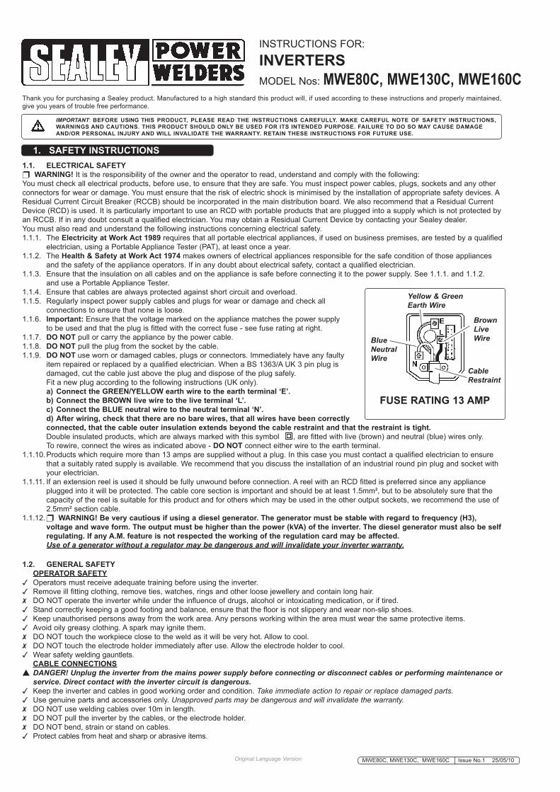
1. SAFETY INSTRUCTIONS1.1. ELECTRICAL SAFETY WARNING! It is the responsibility of the owner and the operator to read, understand and comply with the following:You must check all electrical products, before use, to ensure that they are safe. You must inspect power cables, plugs, sockets and any other connectors for wear or damage. You must ensure that the risk of electric shock is minimised by the installation of appropriate safety devices. A Residual Current Circuit Breaker (RCCB) should be incorporated in the main distribution board. We also recommend that a Residual Current device (RCd) is used. It is particularly important to use an RCd with portable products that are plugged into a supply which is not protected by an RCCB. If in any doubt consult a qualified electrician. You may obtain a Residual Current device by contacting your sealey dealer. You must also read and understand the following instructions concerning electrical safety.1.1.1. The Electricity at Work Act 1989 requires that all portable electrical appliances, if used on business premises, are tested by a qualified electrician, using a Portable Appliance Tester (PAT), at least once a year.1.1.2. The Health & Safety at Work Act 1974 makes owners of electrical appliances responsible for the safe condition of those appliances and the safety of the appliance operators. If in any doubt about electrical safety, contact a qualified electrician.1.1.3. ensure that the insulation on all cables and on the appliance is safe before connecting it to the power supply. see 1.1.1. and 1.1.2. and use a Portable Appliance Tester.1.1.4. ensure that cables are always protected against short circuit and overload.1.1.5. Regularly inspect power supply cables and plugs for wear or damage and check all connections to ensure that none is loose.1.1.6. Important: ensure that the voltage marked on the appliance matches the power supply to be used and that the plug is fitted with the correct fuse - see fuse rating at right.1.1.7. DO NOT pull or carry the appliance by the power cable.1.1.8. DO NOT pull the plug from the socket by the cable.1.1.9. DO NOT use worn or damaged cables, plugs or connectors. Immediately have any faulty item repaired or replaced by a qualified electrician. When a Bs 1363/A UK 3 pin plug is damaged, cut the cable just above the plug and dispose of the plug safely. Fit a new plug according to the following instructions (UK only). a) Connect the GREEN/YELLOW earth wire to the earth terminal ‘E’. b) Connect the BROWN live wire to the live terminal ‘L’. c) Connect the BLUE neutral wire to the neutral terminal ‘N’. d) After wiring, check that there are no bare wires, that all wires have been correctly connected, that the cable outer insulation extends beyond the cable restraint and that the restraint is tight. double insulated products, which are always marked with this symbol , are fitted with live (brown) and neutral (blue) wires only. To rewire, connect the wires as indicated above - DO NOT connect either wire to the earth terminal.1.1.10. Products which require more than 13 amps are supplied without a plug. In this case you must contact a qualified electrician to ensure that a suitably rated supply is available. We recommend that you discuss the installation of an industrial round pin plug and socket with your electrician.1.1.11. If an extension reel is used it should be fully unwound before connection. A reel with an RCd fitted is preferred since any appliance plugged into it will be protected. The cable core section is important and should be at least 1.5mm², but to be absolutely sure that the capacity of the reel is suitable for this product and for others which may be used in the other output sockets, we recommend the use of 2.5mm² section cable.1.1.12. WARNING! Be very cautious if using a diesel generator. The generator must be stable with regard to frequency (H3), voltage and wave form. The output must be higher than the power (kVA) of the inverter. The diesel generator must also be self regulating. If any A.M. feature is not respected the working of the regulation card may be affected. Use of a generator without a regulator may be dangerous and will invalidate your inverter warranty.
FUSE RATING 13 AMP
Blue Neutral Wire
Yellow & Green Earth Wire
Cable Restraint
BrownLive Wire
1.2. GENERAL SAFETY OPERATOR SAFETY operators must receive adequate training before using the inverter. Remove ill fitting clothing, remove ties, watches, rings and other loose jewellery and contain long hair. do NoT operate the inverter while under the influence of drugs, alcohol or intoxicating medication, or if tired. stand correctly keeping a good footing and balance, ensure that the floor is not slippery and wear non-slip shoes. Keep unauthorised persons away from the work area. Any persons working within the area must wear the same protective items. Avoid oily greasy clothing. A spark may ignite them. do NoT touch the workpiece close to the weld as it will be very hot. Allow to cool. do NoT touch the electrode holder immediately after use. Allow the electrode holder to cool. Wear safety welding gauntlets. CABLE CONNECTIONS DANGER! Unplug the inverter from the mains power supply before connecting or disconnect cables or performing maintenance or service. Direct contact with the inverter circuit is dangerous. Keep the inverter and cables in good working order and condition. Take immediate action to repair or replace damaged parts. Use genuine parts and accessories only. Unapproved parts may be dangerous and will invalidate the warranty. do NoT use welding cables over 10m in length. do NoT pull the inverter by the cables, or the electrode holder. do NoT bend, strain or stand on cables. Protect cables from heat and sharp or abrasive items.
Original Language Version MWe80C, MWe130C, MWe160C Issue No.1 25/05/10
2.1. These compact lightweight units are suitable for arc welding using scratch-start method. Automatic Arc-Force circuitry makes the units suitable for arc welding with a wide variety of rods including rutile, basic and stainless from Ø1.6mm up to Ø5.0mm (depending on model). Also includes thermal cut-out and mains voltage leds. Compatible for generator use providing power fluctuation does not exceed +/-15%. Fitted with Hot-start system to counter electrode sticking during scratch starting.
2. INTRODUCTION
3. SPECIFICATION
Model No. .......................................................MWE80C .........................................................MWE130C ...................................................... MWE160C Peak Power: ...................................................80A ..................................................................130A ............................................................... 160A output: ............................................................10 - 80A...........................................................10 - 130A........................................................ 10 - 160A duty Cycle: .....................................................40% @ 80A .....................................................35% @ 130A .................................................. 40% @ 160A electrode Capacity: .........................................Ø1.6 - 2.5mm ..................................................Ø1.6 - 4.0mm ................................................. Ø1.6 - 5.0mm Max Absorbed Power: .....................................2.5kW ..............................................................4.0kW ............................................................. 5.2kW Mains Voltage: ................................................230V - 1ph ......................................................230V - 1ph ..................................................... 230V - 1ph Insulation Class: .............................................B ......................................................................B ..................................................................... B Protection: ....................................................... IP21 ................................................................. IP21 ................................................................ IP21 Weight: ............................................................3.5kg ...............................................................5.0kg .............................................................. 5.0kg ARC Accessory Kit: .........................................Yes (10mm²) ................................................Yes (16mm²) ............................................... Yes (16mm²)
Original Language Version MWe80C, MWe130C, MWe160C Issue No.1 25/05/10
do NoT place cables where they will endanger others. long lengths of slack must be gathered and neatly coiled. do NoT connect the return cable to any metallic structure which is not part of the workpiece. This will jeopardise weld quality and may be dangerous. Exception: Metallic work bench, but connect as near to weld as possible. WARNING! Cable connectors must be fully inserted into the sockets and turned to ensure a good electrical contact. Loose cable connections will cause overheating, rapid deterioration and loss in efficiency. VENTILATION & TOXIC FUMES DANGER! DO NOT weld near flammable materials - solids, liquids, or gases. Severe discomfort, illness or death can result from fumes, vapours, heat, or oxygen enrichment or depletion that welding may produce. ensure that the area has adequate ventilation as welding fumes are harmful. ensure that there is no obstruction to the flow of clean, cool air and ensure that there are no conductive dusts, corrosive vapours or humidity which could enter the inverter and cause serious damage. do NoT weld containers or pipes which have held flammable materials - gases, liquids or solids. DANGER! Avoid welding on materials cleaned with chlorinated solvents or near such solvents. Vapours from chlorinated solvents (such as de-greasers) can be decomposed by the heat of the arc to form PHosGeNe, a highly toxic gas, and other lung and eye irritating products. The ultraviolet (radiant) energy of the arc can also decompose trichloroethylene and perchloroethylene vapours to form phosgene. do NoT weld where solvent vapours can be drawn into the welding or cutting atmosphere or where the radiant energy can penetrate to atmospheres containing even minute amounts of trichloroethylene or perchloroethylene. Prevent dangerous conditions arising by providing adequate ventilation. NeVeR ventilate with oxygen. DANGER! Lead-, cadmium-, zinc-, mercury- and beryllium-, bearing materials, when welded (or cut) may produce harmful concentrations of toxic fumes. Adequate local exhaust ventilation must be used, or each person in the area as well as the operator must wear an air- supplied respirator. For beryllium, both must be used. Metals coated with or containing materials that emit toxic fumes should not be heated unless coating is removed from the work surface, the area is well ventilated, or the operator wears an air-supplied respirator. do NoT work in an unventilated confined space. If necessary, wear an air-supplied respirator. WARNING: Generator engine exhaust must be vented to the outside air. Carbon monoxide can kill. PROTECTION FROM ARC WARNING: Use welding head shield to protect eyes and avoid exposing skin to ultraviolet rays given off by electric arc. looking at an arc momentarily with unprotected eyes (particularly a high intensity gas-shielded arc) can cause a retinal burn that may leave a permanent dark area in the field of vision. Before welding whilst wearing contact lenses, seek advice from your optician. Avoid unintentional contact with workpiece. Accidental or uncontrolled arcing on the electrode holder may be dangerous. do NoT hit the electrode on the workpiece, this may damage the electrode and make strike-up difficult. Wear safety welding gauntlets. WELDING ENVIRONMENT locate the inverter in a suitable work area. see section 11 regarding electromagnetic Compatibility. Keep the work area clean and tidy and free from unrelated materials. Also ensure that the work area has adequate lighting. do NoT get inverter wet or use in damp or wet locations or areas where there is condensation. First aid facilities and a qualified first aid person should be available during welding operations. For production welding, a separate room or enclosed bay should be provided. In open areas, surround the operation with low reflective, non-combustible screens or panels. Allow for free air circulation, particularly at floor level. Provide face shields for all persons who will be looking directly at the weld. Before starting to weld, make sure that screen or bay doors are closed. AlWAYs ensure that there is full free air circulating around the outer casing of the machine, and that the louvres are unobstructed. FIRE HAZARD WARNING: Be aware that flying sparks or falling slag can pass through cracks, along pipes, through windows or doors, and through wall or floor openings, out of sight of the operator. Sparks and slag can fly 10m. do NoT weld within 10 metres of combustible materials (including building construction materials). do NoT weld adjacent to openings (concealed or visible) in floors or walls within 10m that can expose combustibles to sparks. do NoT weld near to walls, ceilings, roofs or metal partitions where there are combustibles that can be ignited by radiant or conducted heat. Have suitable fire extinguishing equipment available and someone to use it during welding operations and for some time after welding ceases. After work is done, check that area is free of sparks, glowing embers, and flames. PRODUCT CARE & MAINTENANCE do NoT attempt to fit any unapproved electrode holder, components, or parts to the inverter unit. When not in use, store the inverter in a safe, dry, childproof area. Keep the inverter clean for best and safest performance. WARNING: If the case is opened for maintenance or repair, wait 10-15 seconds after the unit is switched off for the capacitor to discharge. do NoT remove any of the panels unless the machine is disconnected from the supply, do NoT use the inverter with any of the panels removed.
Original Language Version MWe80C, MWe130C, MWe160C Issue No.1 25/05/10
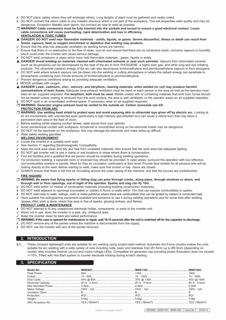
4. CABLE CONNECTION WARNING! Ensure that the inverter is not plugged into the mains power supply before connecting or disconnecting cables. For electrical installation, see Safety Instructions (Section 1). WARNING! Failure to follow the electrical safety instructions may affect the operating performance and could damage the built-in safety system which, in turn, could result in personal injury or fatality and will invalidate the warranty.4.1. WELDING CABLE “ELECTRODE HOLDER” CONNECTION Before connecting cables it is important to refer to the electrode manufacturer’s instructions on the electrode packaging which will indicate the correct polarity connection for the electrode, together with the most suitable current to use.4.2. ARC WELDING In principle, when ARC welding the electrode Holder ”PosITIVe” is normally connected to the “PosITIVe” (+) terminal (fig. 1).
4.3. WELDING “RETURN CABLE” - (WORK CLAMP) CONNECTION The WoRK ClAMP cable is connected to the terminal not occupied by the electrode holder cable. The clamp is connected to: a) The workpiece, or b) A metallic work bench. The connection must be as close to the proposed weld as possible. WARNING! Cable connectors must be turned fully into the quick plugs to ensure a good electrical contact. Loose connections will cause overheating, rapid deterioration and loss in efficiency. DO NOT use welding cables over 10m in length. With the exception of a metallic workbench DO NOT connect the return cable to any metallic structure which is not part of the workpiece, as this will jeopardise weld quality and may be dangerous. MWE130C, MWE160C
fig.1
5. CONTROLS
6. PREPARATION
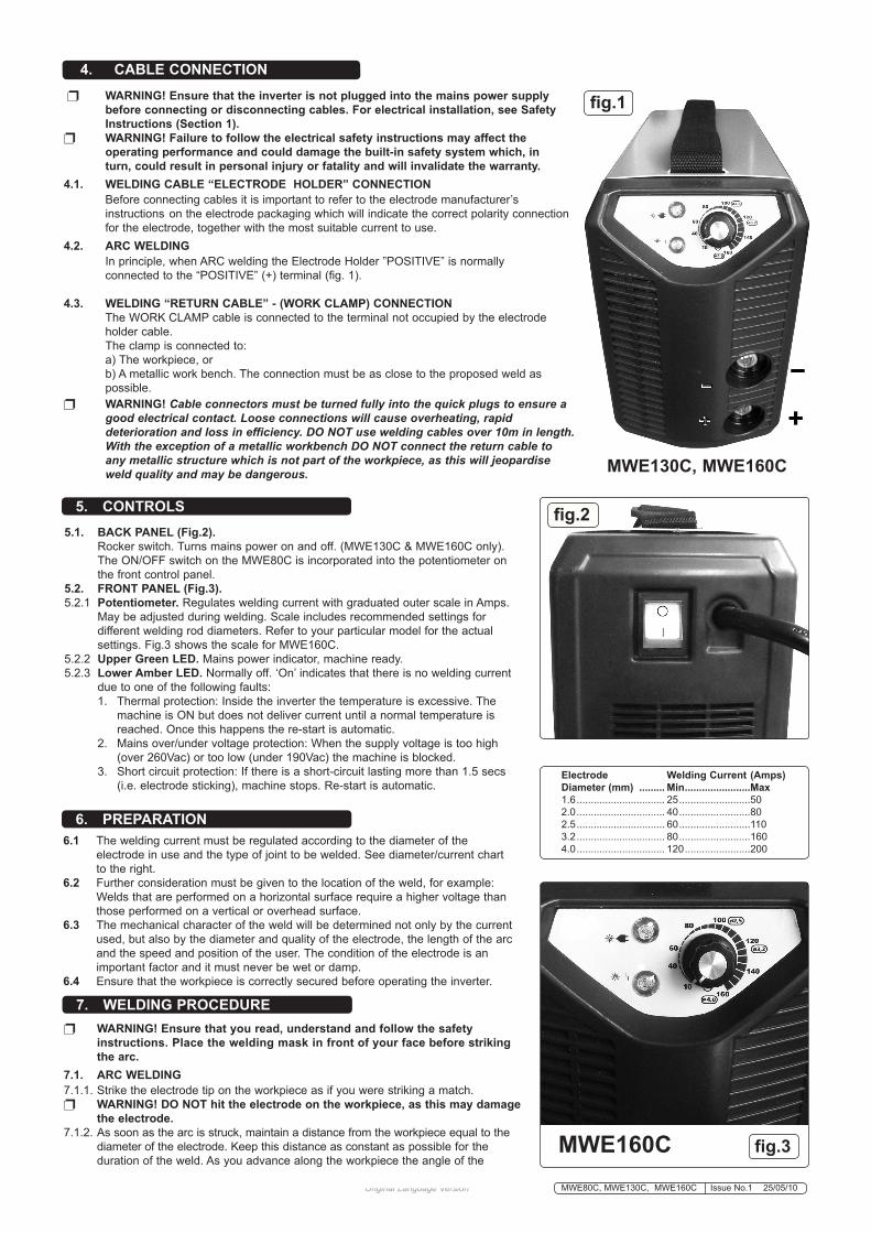
5.1. BACK PANEL (Fig.2). Rocker switch. Turns mains power on and off. (MWe130C & MWe160C only). The oN/oFF switch on the MWe80C is incorporated into the potentiometer on the front control panel.5.2. FRONT PANEL (Fig.3).5.2.1 Potentiometer. Regulates welding current with graduated outer scale in Amps. May be adjusted during welding. scale includes recommended settings for different welding rod diameters. Refer to your particular model for the actual settings. Fig.3 shows the scale for MWe160C. 5.2.2 Upper Green LED. Mains power indicator, machine ready.5.2.3 Lower Amber LED. Normally off. ‘on’ indicates that there is no welding current due to one of the following faults: 1. Thermal protection: Inside the inverter the temperature is excessive. The machine is oN but does not deliver current until a normal temperature is reached. once this happens the re-start is automatic. 2. Mains over/under voltage protection: When the supply voltage is too high (over 260Vac) or too low (under 190Vac) the machine is blocked. 3. short circuit protection: If there is a short-circuit lasting more than 1.5 secs (i.e. electrode sticking), machine stops. Re-start is automatic.
6.1 The welding current must be regulated according to the diameter of the electrode in use and the type of joint to be welded. see diameter/current chart to the right. 6.2 Further consideration must be given to the location of the weld, for example: Welds that are performed on a horizontal surface require a higher voltage than those performed on a vertical or overhead surface.6.3 The mechanical character of the weld will be determined not only by the current used, but also by the diameter and quality of the electrode, the length of the arc and the speed and position of the user. The condition of the electrode is an important factor and it must never be wet or damp.6.4 ensure that the workpiece is correctly secured before operating the inverter.
WARNING! Ensure that you read, understand and follow the safety instructions. Place the welding mask in front of your face before striking the arc.7.1. ARC WELDING7.1.1. strike the electrode tip on the workpiece as if you were striking a match. WARNING! DO NOT hit the electrode on the workpiece, as this may damage the electrode.7.1.2. As soon as the arc is struck, maintain a distance from the workpiece equal to the diameter of the electrode. Keep this distance as constant as possible for the duration of the weld. As you advance along the workpiece the angle of the
7. WELDING PROCEDURE
fig.2
fig.3MWE160C
Electrode Welding Current (Amps) Diameter (mm) ......... Min .......................Max 1.6 ............................... 25 .........................50 2.0 ............................... 40 .........................80 2.5 ............................... 60 .........................110 3.2 ............................... 80 .........................160 4.0 ............................... 120 .......................200

10. RATINGS PLATE The ratings plate on the inverter gives the following data: 1 - Rating of internal protection provided by casing. 2 - symbol for power supply line: 1= single-phase AC. 3 - S: Indicates that welding may be carried out in environments with a heightened risk of electric shock e.g. very close to large metallic objects. 4 - Welding procedure: manual arc welding with covered electrode 5 - symbol for internal structure of the welding machine. 6 - The eURoPeAN standard relating to the safety and construction of arc welding machines.. 7 - Manufacturers serial Number for welding machine identification. 8 - output Uº: Maximum no load voltage. I², U²: Current and corresponding normalised voltage that the welding machine can supply during welding. X: Welding ratio based on a 10 minute duty cycle. 30% indicates 3 minutes welding and 7 minutes rest, 100% indicates continuous welding. A/V-A/V: shows the range of adjustment for the welding current (minimum - maximum) at the corresponding arc voltage. 9 - Power supply U1: Alternating voltage and power supply frequency of welding machine. (allowed limit ± 10%) I1 max: Maximum current absorbed by the line. I1 eff: effective current supplied. 10 - size of delayed fuse for protection of power supply. 11 - symbols referring to safety regulations.
9. TROUBLESHOOTING If you have a problem with the inverter, check to ensure that the following are correct:● Check that the welding current, which is controlled by the potentiometer (fig.3), is suitable for the diameter and type of electrode being used.● When the mains switch is on, check that the green mains lamp is on. If this is not the case then there may be a mains supply problem.● Check the amber led - has the thermal cut-out activated? This indicates either an over or under voltage or short circuit. If the thermal interrupter has activated, wait for the machine to cool down before restarting.● Check the nominal interruptance ratio is correct, and check that the fan is working correctly.● ensure that you are using the correct supply voltage. ● Check the machine output and ensure there is nothing causing a short-circuit.● Check that all circuit connections are correct. In particular check that the work clamp is correctly attached to the workpiece. ensure that there is no grease, paint etc. on the surface.
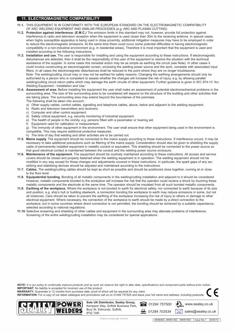
electrode must be maintained at between 20º and 30º. see fig.4.7.1.3. At the finish of the weld, bring the end of the electrode backward in order to fill the weld crater and then quickly lift the electrode from the weld pool to extinguish the arc. WARNING! Hot metal such as electrode stubs and workpieces should never be handled without gloves.
8 . MAINTENANCE WARNING! BEFORE CARRYING OUT ROUTINE MAINTENANCE, SWITCH OFF THE WELDING MACHINE AND DISCONNECT IT FROM THE MAINS POWER SUPPLY. WARNING! IF THE WELDING MACHINE IS NOT FUNCTIONING PROPERLY REPAIRS SHOULD BE CARRIED OUT ONLY AND EXCLUSIVELY BY AUTHORISED SERVICE ENGINEERS. WARNING! BEFORE REMOVING THE WELDING MACHINE PANELS, SWITCH OFF THE MACHINE AND DISCONNECT IT FROM THE MAINS POWER SUPPLY. Wait 10-15 seconds after the unit is switched off for the capacitor to discharge.8.1 Periodically remove the casing and, with a low pressure air flow (max 10bar), remove dust from inside the machine. 8.2 do not direct compressed air onto the electronic circuit boards, these should be cleaned with a very soft brush.8.3 ensure that all electrical connections are tight and check the wiring for damage to the insulation.8.4 ensure that the casing is correctly replaced and secured before attempting to use the inverter.8.5 Keep the outside of the machine clean by wiping with a soft, dry cloth.8.6 do not direct compressed air onto the electronic circuit boards, these should be cleaned with a very soft brush.8.7 ensure that all electrical connections are tight and check the wiring for damage to the insulation.8.8 ensure that the casing is correctly replaced and secured before attempting to use the inverter.8.9 Keep the outside of the machine clean by wiping with a soft, dry cloth. For any other service or maintenance, contact your local Sealey service agent.
Original Language Version
fig.4
MWe80C, MWe130C, MWe160C Issue No.1 25/05/10
11. ELECTROMAGNETIC COMPATIBILITY11.1. THIs eQUIPMeNT Is IN CoNFoRMITY WITH THe eURoPeAN sTANdARd oN THe eleCTRoMAGNeTIC CoMPATIBIlITY oF ARC WeldING eQUIPMeNT ANd sIMIlAR PRoCesses (e.g. ARC ANd PlAsMA CUTTING)11.2. Protection against interference. (E.M.C.) The emission limits in this standard may not, however, provide full protection against interference to radio and television reception when the equipment is used closer than 30m to the receiving antenna. In special cases, when highly susceptible apparatus is being used in close proximity, additional mitigation measures may have to be employed in order to reduce the electromagnetic emissions. At the same time there could occur some potential difficulties in having electromagnetic compatibility in a non-industrial environment (e.g. in residential areas). Therefore it is most important that the equipment is used and installed according to the following instructions.11.3. Installation and use. The user is responsible for installing and using the equipment according to these instructions. If electromagnetic disturbances are detected, then it shall be the responsibility of the user of the equipment to resolve the situation with the technical assistance of the supplier. In some cases this remedial action may be as simple as earthing the circuit (see Note). In other cases it could involve constructing an electromagnetic screen, enclosing the welding power source and the work, complete with associated input filters. In all cases the electromagnetic disturbances shall be reduced to the point where they are no longer troublesome. Note: The welding/cutting circuit may or may not be earthed for safety reasons. Changing the earthing arrangements should only be authorised by a person who is competent to assess whether the changes will increase the risk of injury, e.g. by allowing parallel welding/cutting circuit return paths which may damage the earth circuits of other equipment. Further guidance is given in IeC 974-13 ’Arc Welding equipment - Installation and Use.’11.4. Assessment of area. Before installing the equipment the user shall make an assessment of potential electromechanical problems in the surrounding area. The size of the surrounding area to be considered will depend on the structure of the building and other activities that are taking place. The surrounding area may extend beyond the boundaries of the premises. The following shall be taken into account : a) other supply cables, control cables, signalling and telephone cables, above, below and adjacent to the welding equipment. b) Radio and television transmitters and receivers. c) Computer and other control equipment. d) safety critical equipment, e.g. security monitoring of industrial equipment. e) The health of people in the vicinity, e.g. persons fitted with a pacemaker or hearing aid. f) equipment used for calibration or measurement. g) The immunity of other equipment in the environment. The user shall ensure that other equipment being used in the environment is compatible. This may require additional protective measures. h) The time of day that welding and other activities are to be carried out.11.5. Mains supply. The equipment should be connected to the mains supply according to these instructions. If interference occurs, it may be necessary to take additional precautions such as filtering of the mains supply. Consideration should also be given to shielding the supply cable of permanently installed equipment in metallic conduit or equivalent. This shielding should be connected to the power source so that good electrical contact is maintained between the conduit and the welding power source enclosure.11.6. Maintenance of the equipment. The equipment should be routinely maintained according to these instructions. All access and service covers should be closed and properly fastened when the welding equipment is in operation. The welding equipment should not be modified in any way except for those changes and adjustments covered in these instructions. In particular, the spark gaps of any arc striking and stabilising devices should be adjusted and maintained according to the instructions.11.7. Cables. The welding/cutting cables should be kept as short as possible and should be positioned close together, running at or close to the floor level.11.8. Equipotential bonding. Bonding of all metallic components in the welding/cutting installation and adjacent to it should be considered. However, metallic components bonded to the workpiece will increase the risk that the operator could receive a shock by touching these metallic components and the electrode at the same time. The operator should be insulated from all such bonded metallic components. 11.9. Earthing of the workpiece. Where the workpiece is not bonded to earth for electrical safety, nor connected to earth because of its size and position, e.g. ship’s hull or building steelwork, a connection bonding the workpiece to earth may reduce emissions in some, but not all instances. Care should be taken to prevent the earthing of the workpiece increasing the risk of injury to others or damage to other electrical equipment. Where necessary, the connection of the workpiece to earth should be made by a direct connection to the workpiece, but in some countries where direct connection is not permitted, the bonding should be achieved by a suitable capacitance, selected according to national regulations.11.10. selective screening and shielding of other cables and equipment in the surrounding area may alleviate problems of interference. screening of the entire welding/cutting installation may be considered for special applications.
Original Language Version MWe80C, MWe130C, MWe160C Issue No.1 25/05/10
NOTE: It is our policy to continually improve products and as such we reserve the right to alter data, specifications and component parts without prior notice.IMPORTANT: No liability is accepted for incorrect use of this product. WARRANTY: Guarantee is 12 months from purchase date, proof of which will be required for any claim. INFORMATION: For a copy of our latest catalogue and promotions call us on 01284 757525 and leave your full name and address, including postcode.
01284 757500
01284 703534 [email protected]
Sole UK Distributor, Sealey Group, Kempson Way, suffolk Business Park, Bury st. edmunds, suffolk,IP32 7AR
www.sealey.co.ukWeb