instructions - electricalpartmanuals.com...i.l. 41-891 instructions type cn-33p primary networ1<...
TRANSCRIPT

I .L . 41-891
INSTRUCTIONS
TYPE CN-33P PRIMARY NETWOR1< RELAY
c AuT 1 oN: Before putting relays into service, re
move all blocking which may have been inserted for
the purpose of securing the parts during shipment,
make sure that all moving parts operate freely, in
spect the contacts to see that they are clean and
close properly, and operate the relay to check the
settings and electrical connections.
APPLICATION The type CN33P relay supplies the tripping and
closing requirements of a primary disfribution net
work relay. These requirements are:
1. Close its TRIP contacts for primary supply line
or network transformer faults.
2. Close its TRIP contacts, when the primary supply
line breaker is open, and the network is ener
gfzing the transformer. The current which flows
can be either the transformer magnetizing current
or a combination of the magnetizing current and
the primary line charging current.
3. Not close its TRIP contacts for faults within the
network.
4. Close its CLOSE contacts when the relation
between the primary supply voltage and the net
work voltage is such as to cause power to flow
from the primary supply line to the network.
5. Not close its CLOSE contacts when the relation
between the feeder voltage and the network
voltage is such as to cause power to flow from
the network to the feeder. A CNJ relay is also
needed to completely fulfill this requirement.
6. Not to close its CLOSE contacts for reverse
phase conditions; that is, when the conductor
phase sequence is not the same on each side of
the breaker.
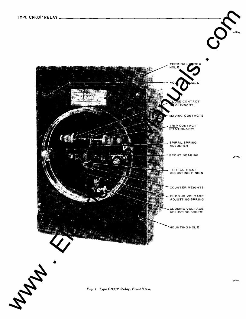
CONSTRUCTION The type CN-33P primary network relay, shown
in Figs. 1 & 2, is a three phase relay which oper-
NEW INFORMATION
ates on the induction principle. Its moving element
is a drum carried on a horizontal shaft which ro
tates on knife edge bearings. Since this type of
bearing is placed at the center of the shaft, friction
is reduced to a minimum. Phosphor bronze retaining
rings encircle the ends of the drum shaft. End
thrust is taken care of by means of flat polished
steel surfaces in the stationary bearing assembly
screws. The ends of the drum shaft are conical,
and one end or the other makes point contact with
its associated flat steel surface depending upon the
direction of thrust.
The relay has single pole, double throw con
tacts made of pure silver. The moving contact arm
carries two spring mounted silver contacts which
are electrically one, and one flat steel spring which
extends down from the shaft. This spring deter
mines the amount of phasing voltage n ecessary to
close the CLOSE contacts of the relay. Counter
weights are also carried on the moving arm so that
the moving element is substantially balanced in
all positions.
The block which carries the stationary CLOSE
contacts is mounted to the left (Front View) of the
moving contact on the insulation plate through which
the drum shaft passes, and is stamped with the
letter "C". The block which carries the stationary
TRIP contact is mounted to the right of the moving
contact and is stamped with the letter "T".
On the lower part of the insulation plate is
mounted another brass block with three tapped holes
in it. This block carries a small thumb screw which
acts as a stop to deflect the phasing voltage spring.
This phasing voltage spring adjuster is used to vary
the amount of phasing voltage necessary to close
the CLOSE contacts.
When the relay is completely deenergized the
moving contact is held against the TRIP stationary
contact by means of the spiral spring. The inner
end of this spring is fastened to the moving con
tact arm and the outer end is fastened to a spring
adjuster which is on the front of the insulation plate.
EFFECTIVE JANUARY 1960 www . El
ectric
alPar
tMan
uals
. com
TYPE CN-33P RELAY--------------------------------------------------------
Fig, 1 Type CN33P Relay, Front View,
2
TERM INA L S CREW
HOLE
CLOSE CONTACT
(STATIONARY)
MOVING C ONTACTS
TRIP CONTACT
(STATIONA RY)
SPIRA L SPRING
ADJUSTER
FRONT BEARING
TRIP C URRENT
ADJUST ING PINION
COUNTER WE IGHTS
CLOSING VOLTAGE
ADJUSTING SPRING
CLOS ING VOLTAGE
ADJUSTING SCREW
MOUNTING HOLE
www . El
ectric
alPar
tMan
uals
. com
TYPE CN-33P RELAY -----------------------------=I:.:. L::..· .=_4.:..::.1·8:::..: 9...:.1
TERMINAL SC REW
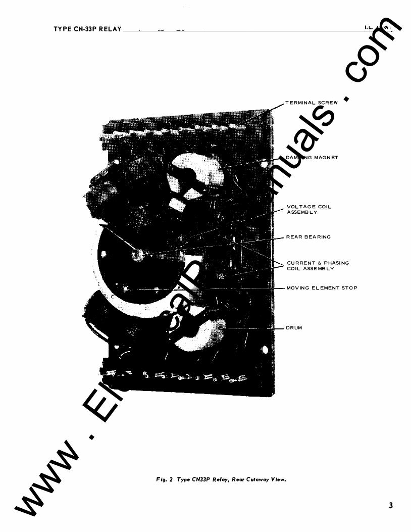
Fig. 2 Type CN33P Relay, Rear Cutaway View.
DAMPING M AGNET
VOLTAGE COIL
ASSEMBLY
REAR BEA RING
CURRENT 8: PHASING
COIL AS SE MBLY
M OV ING E LEMENT STOP
D R UM
3 www . El
ectric
alPar
tMan
uals
. com

TYPE CN-�P RELAY------------------------------------------------------�
TERMINALS-
__ ....:.Wl!!!'RI"-'NG �J,AGR::;:AM:___ __
�J+� ...
REAR VIEW WlTH INSTANTAIEOUS POLARITES AS SHO'Mt, •t• CONTACTS CLOSE WHEJI CURRENT AIID POTENTIAL COILS ARE ENERGIZED AND •c• CONTACTS CLOSE WHEN PHASING AND POTENTIAL COILS ARE ENERGIZED.
CURREJIT COIL
PHASING COIL
57-D-4571 Fig, 3 Internal Schematic oiType CN33P Relay, Slt7731270.
Gear teeth on the adjuster engage the pinion, the
insulation shaft of which extends through a hole in
the front bearing plate. The spring tension is easily
adjusted by rotating the pinion with a screw driver
without danger of grounding the assembly. This
adjustment is located under the glass cover to pre
vent unauthorized changing of the adjustments.
The moving element stop, which is a pin in the
drum, operates in a large clearance hole in the rear
bearing plate and limits the movement of the drum in
both directions by striking the opposite sides of
this hole.
The three electromagnets which are carried on
the back of the steel mounting plate are mounted
radially and equally spaced about the drum. Each
electromagnet consists of a conventional potential
coil and iron assembly mounted inside the drum and
a current and phasing coil and iron assembly mounted
on the same radial centerlines outside the drum.
Each current and phasing coil and iron assembly
is securely fastened to the back of the mounting
plate by two screws.
Molded insulation terminal blocks are mounted
on the two ends of the mounting plate. Silver tip
screws pass through the terminal blocks in the relay
4
base and engage the stationary terminals in the
external blocks. These stationary terminal blocks
have silver plated copper jaws which are backed up
by steel springs assembled in the molded insulation
blocks.
The relay is mounted on two studs and held
securely in place by two nuts, which when tightened,
force the terminal screws firmly into engagement
with their associated jaws. These jaw assemblies
are free to move in their molded insulation blocks
so as to be self aligning. The heads of all terminal
screws are accessible from the front of the relay,
and when they are screwed down in their normal
position the heads are completely surrounded by the
molded terminal blocks through which the screws
pass. This prevents accidental contact with per
sonnel, or shorting to ground or between screws.
By partially removing the proper terminal screw or
screws any circuit or circuits between the relay and
the external wiring can be opened. Before the head
of the screw becomes flush with the surface of the
terminal block the circuit is opened. The screw
remains connected to its associated relay circuit
even after it is backed out until its head extends
above the surface of the molded block, so that a
test clip can be connected to it.
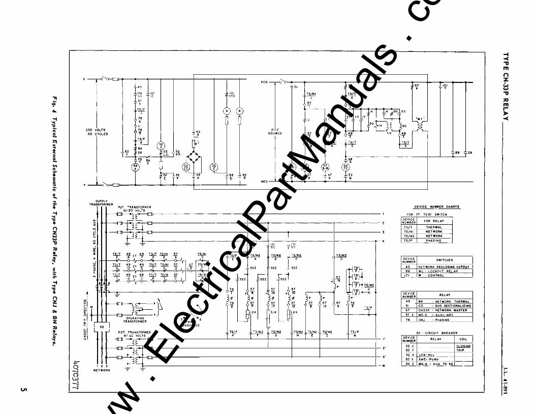
OPE RATION The operation of the type CN33P relay can best
be described by referring to Fig. 4. Fig. 4 shows
a typical external schematic diagram of the type
CN33P, the type CNJ (I.L. 4 1-893), and the type BN (I.L. 41-894) relays, when used on a three phase,
4-wire, primary network with wye -wye potenti'al
transformers and wye connected current transformers.
Assume the system to be deenergized. When the
CN33P is deenergized its TRIP contacts will be
held closed by the spiral spring. The CN-J CLOSE
contact will be held open. The BN contacts will be
opened. If the primary supply breaker is closed
energizing the transformer, the phase 2 potential
coil of the CN33P will be energized. The supply
voltage will also be applied to the phasing circuits.
The phasing resistor of phase 2 has been proportioned
to give sufficient torque to close the CLOSE con
tacts when the relay is energized from the supply
side only. Therefore, the breaker will close and
connect the transformer to the network since the
CLOSE contacts of both the CN33P and the CNJ
are closed.
Again, refer to Fig. 4 and the original conditions:
www . El
ectric
alPar
tMan
uals
. com
., � ..... -1 � n .!!.. Ill )C .. !t :I .!!.. "' n :r-.. 3 a .. n 0 .... .. I SUPPLY :r- TRANSFORMER CD -1 � <I> CD :> .. 0 � ::.:: � w u w g , ;o
jj !!. llii � E
!. .. :r--1 "( 'tJ CD 0 ::.:: ... "" !D ::.:: ;o " Q "( �
I +=" 0 I 2 3 --l NETWORK 0 U,) --l
(.n I -.J
lL lL 't_:_
f
101 c
49 ar T 1_2 7 IU! !Mil 0 E
•• 10 •• 12
...
IT� llii � F G
IT� !W IM!l H I
lE:� 'IATING iFORMER
�NSFORMER I VOLTS
lC -;ur-
3C -;ur
lL "-"
"' lliH! 8 ,-4---57
57 � 15 +• F
57 !2m!. II L4-
I
,�J PHASE
SEQUENCE
101 cro
�2 ...1.. �2 b T a
� E
,-----52Z
78 T + 9!
78 2
L__
!:¥
101 sc
POS. _____,_, "t 151 1 � ": � "l I � 1�1 1 l
o.:.c SOURCE
NEG.
CW!_I J "' T
"' 3
57 2 � +TS�Nt
TS/T �.�
86 :::!:Z6
DEVICE NUMBER CHARTS
FOR FT TEST SWITCH
DEVICE FOR RELAY NUMBER TS/T THERMAL TS/NI NETWORK TS/N2 NETWORK TS/P PHASING
� r� f� ill!!.& •
52Z
,-----52Z
57
52Z 52Z
,----52Z
57 "' 9
+�� +�: 9! "' 5
7 57
T T'l 12 l.2K 3.1K �1.2K
�----� �
f:IS{
"' � T�N2 G
--H-
D
"' + 18 p
� :7 p "' 57 6 TI 5
f�� � I
DEVICE NUMBER
"l�·-k� k7i TS/N2 k7.J J
3p 6
78
43 86
�_9_1__
DEVICE NUMBER
•• , � I
5I 5
7 57 X 78
� H I' DEVICE
NUMBER
.. _5_.? __ c ��T
3' 5_g_ X_ •• y
N 52 z
SW ITCHES
NETWORK RECLOSING CUTQ!/T WL - LOCKOUT RE AY w - CONTROL
RELAY
8N - NETWORK THERMAL co - BUS SECT!ONALIZING CN33P - NETWORK MASTER M G·6 AUXIL IARV CNJ - PHASING
52 • CIRCUIT BREAKER
RELAY
-�--
��Mp--MG�6 - AUX. TO �2
COIL
CLOSING I TRIP
-1 -< ., m n z w w ., ::0 m .� -<
r �
�
www . El
ectric
alPar
tMan
uals
. com

TYPE CN-33P RELAY-----------------------------
330 340 380 0 10 2 0 30
320
310
290
280
260 100
2!50
130
140
210 200 190 180 170 160 150
Curve 471102
Fig. 5 Typical Closing Phase Angle Curve lor the CN33P Relay.
6 www . El
ectric
alPar
tMan
uals
. com

TYPE CN-33P R ELA Y ____________________________ .::•· .:::L :....:4!.!1- :..289!..!.1
eeo
260
40
TYPICAL TRIP CURVE FOR CN-33P
(CURRENT APPLIED DIRECT ' THROUGH THE RELAY COILS, SO NO C.T.'S.)
100
110
120
Curve 471107
Fig. 6 Typical Tripping Phase Angle Curve for the CN33P Relay- High Current Values,
that is, that all feeders associated with the network
are open. Now suppose that some network supply
line, other than the one to which the transformer
bank of Fig. 4 is connected is energized by closing
its breaker at the supply station. The breaker on
that feeder will close and energize the network as
has been explained. This energizes the network,
and the phase 1 and 3 potential coils and all phasing
circuits of the CN33P become energized. The
phasing circuits of all phases have essentially full
voltage on them but since the voltage on the network
side of the breaker is the higher, a strong torque is
produced which keeps the TRIP contacts closed.
With the network energized, assume that the
primary supply breaker closes to energize the net
work transformer in question. If the supply and
network voltages are in phase, the phasing voltage
will be zero . In this case there will be no electrical
torque produced, except the "voltage only" torque
produced by the potential coils. This torque is suf
ficient to overcome the tension of the spiral spring.
Thus, the voltage only torque opens the TRIP con_
tact. However, there is not enough torque to close
the CLOSE contact, so the CN33P does not close the
breaker.
With the network energized, assume that the net
work transformer in question is energized, such that
the transformer secondary voltage is higher than the
network voltage, and substantially in phase with it.
In this case, the phasing coils in conjunction with
the potential coils will produce a torque which will
cause the moving contact of the CN33P relay to make
with the stationary CLOSE contact and close the
network breaker, thus connecting the transformer bank
to the network, provided the CNJ contacts are
closed.
The instant the breaker closes, power starts to
flow from the transformer into the network. This
causes current to flow in the current coils of the
relay. and produces a stronger torque in the closing
direction. The network breaker will remain closed
even if conditions change so that there is no current
flowing through it. As the current decreases to
7 www . El
ectric
alPar
tMan
uals
. com

TYPE CN-33PRELAY ______________________________________________________ __
Curve 471108
Fig. 7 Typical Trip Phase Angle Curve for the CN33P Relay- Low Current Values.
zero, the moving contact will move away from the
stationary CLOSE contact and take up a position
somewhere between it and the stationary TRIP
contact.
When the feeder breaker opens, the transformer
will be magnetized from the network. This flow of
exciting current from the network to the transformer
bank will cause enough current to flow in the current
coils in the type CN33P relay to produce a tripping
torque sufficient to close the TRIP contacts. This
energizes the BN relay which will trip the breaker
when its timer contacts have closed. The timer
contacts are shunted by the instantaneous triP con
tacts which close when the reverse current exceeds
their setting.
Fig. 4 shows the phasing coils short circuited
through a resistance by 52ri contacts when the
breaker is closed. This circuit is used to obtain
the desired tripping phase angle characteristic.
8
CHARACTER ISTICS Figures 5, 6 & 7 show the operating character
istics of the type CN33P primary network relay for
balanced 3 phase conditions. Fig. 5 shows the
closing characteristics of the relay. For curve #lA,
lines drawn from the origin at various angles with
respect to the· network voltage represent both in
magnitude and phase position the transformer voltage
which will produce a torque in the relay just suffi
cient to cause its CLOSE contacts to make. Any
transformer voltage which does not terminate on or
above the closing curve will produce a relay torque
in the tripping direction. Curve #lA in fig. 5 shows
a small section of the closing curve plotted to a
much larger scale so as to show the characteristics
of the relay for the values of phasing voltage at which
it normally operates. Lines drawn from the origin
to this curve represent in magnitude and phase po
sition the phasing voltage (the voltage across the
open breaker) necessary to produce a torque in the
relay just sufficient to make its CLOSE contacts.
www . El
ectric
alPar
tMan
uals
. com
TYPE CN-33 P RELAY --------------------------__::'·:..=L.:... ".:...:'...:- 8.;..9 1:......
w ..
11!5"11.
IN-PHASE TRIPPING CHARACTERISTICS OF THE CN-33P PRIMARY NETWORK RELAY 1-t+c-+'-H-H+!+H-H-t+h i --
�; =-" :..; :- �: 't
; g 8!5��------��+rtrtT��.�+-������ " 0:
� I;; z
. 2
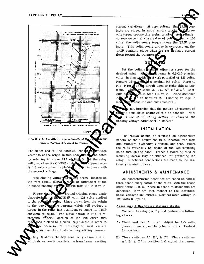
Curve 471109 Fig, 8 Trip Sensitivity Characteristic ol the Type CN33P
Relay- Voltage & Current In Phase.
The upper end or line potential end of the voltage
vector is at the origin in this case. It will be noted
by referring to curve #1A of Fig. 5 that the relay
will just close its CLOSE contacts with approximate
ly 0.5 volts across the phasing circuit, in phase with
the network voltage.
The closing voltage adjusting screw, located on
the front panel, allows a range of adjustment of the
in-phase phasing voltage pickup from 0.5 to 2 volts.
Figure 6 and 7 show typical tripping phase angle
characteristic of the CN33P with 125 volts applied
to the potential coils. Lines drawn from the origin
to the curve are the currents which will produce a
torque in the relay just sufficient to cause its TRIP
contacts to make. The curve shown in Fig. 7 re
presents a small section of the trip curve just
discussed plotted to a much larger scale in order to
show the operation of the relay on small current
values, such as the transformer magnetizing currents.
Fig. 8 shows the trip sensitivity characteristic,
which shows how it parallels the transformer exciting
current variations. At zero voltage, the TRIP con
tacts are closed by spiral spring tension. Voltage
only torque oppose this spring tension. Accordingly,
at zero current & some value of voltage, below 100
volts, the voltage-only torque opens the TRIP con
tacts. This voltage-only torque is overcome and the
TRIP contacts close when 2-4 rna in-phase current
flows toward the transformer.
SETTINGS Set the voltage closing adjusting screw for the
desired value. Adjustment range is 0.5-2.0 phasing
volts, in phase with a network potential of 125 volts.
Factory adjustment is a nominal 0.5 volts. Refer to
Fig. 9 for the test circuit used to make this adjust
ment. (Close switches A, B c. A", B:' & C ". Ener
gize potential coils with 125 volts. Place switches
A 1, B 1 & c 1 in position 2. Phasing voltage is
measured across the one ohm resistors.)
It is not intended that the factory adjustment of
the trip sensitivity characteristic be changed. Note that if the spiral spring setting is changed, the
phasing voltage adjustment is affected .
INSTALLATION The relays should be mounted on switchboard
panels or their equivalent in a location free from
dirt, moisture, excessive vibration, and heat. Mount
the relay vertically by means of the two mounting
holes through the case. Either a mounting stud or
mounting screw may be utilized for grounding the
relay. Electrical connections are made to the sta
tionary terminal blocks.
ADJUSTMENTS & MA INTENANCE All characteristics described are based on normal
three-phase energization of the relay , with the phase
order being 1, 2, 3. Where in-phase relationships are
described, they are with respect to the individual
phase voltages and current. Nominal rated voltage is
125 volts 60 cycles.
Acceptance & Routine Maintenance checks
Connect the relay per Fig. 9 & perform the follow
ing checks:
A) Close swit ches A, B, C. Adjust for 125 volts,
phase to neutral, on the potential coils. Preheat
for one hour.
B) Close switches A", B", & C". Place switches
A 1, B 1 & C 1 in position 1 & adjust the current
9 www . El
ectric
alPar
tMan
uals
. com

TYPE CN-33P RELAY ______________________________________________________ __
PHASf ROTATION I t
290B223 Fig. 9 Test Connections for Type CN33P Relay.
in MAl, MA2 & MA3 until the TRIP contacts just
close. This current should be 2-4 rna. (All three
currents should be the same). Potent ial coils
should be energized at 125 volts.
C) Open switches A", B" & C" & reduce voltage on
potential coils until TRIP contacts close. This
potential should be 100 volts or less, line to
neutral.
D) Close switches A", B" & C". Place switches
A ', B ' & C ' in position 2. Energize potential
coils at 125 volts, phase to neutral. Adjust the
phasing voltage (voltage across one ohm resis
tors) until CLOSE contacts just close. This
value should be 0.5-0.8 volts.
Calibration
If the acceptance or routine maintenance check
has shown further adjusting necessary, the following
procedure may be used to recalibrate the relay.
Mechanical Adjustment
A. Set contacts (See Settings). The moving contacts
10
are adjusted such that the contact springs are
just touching their support. Just touching is
determined as follows: With t he relay vertical,
as it would be mounted, the moving contact
springs should be touching their respective
supports. Turn the relay counter clockwise until
the moving contact is horizontal. The weight of
the moving TRIP contact should move the con
tact spring away from its support. Turn the
relay horizontally in the opposite direction
(clockwise) and the CLOSE moving contact spring
should move away from its support.
B. Adjust the end play of the drum shaft to approx
imately .003 to .010 inches by setting the front
bearing.
C. Check the position of the moving contact as
sembly in relation to the moving element stops.
It should move about an equal distance on either
side of the vertical center line with the station
ary contacts moved back. If the position is not
correct then loosen the two screws in the counter-
www . El
ectric
alPar
tMan
uals
. com

TYPE CN-33P RELAY ___________________________ ____;I�.L:.:..· ....:.4.:....1·.::..:89 ....:..1
weights and adjust. The inner spring support
should not touch the spiral spring adjuster.
D. Adjust the stationary contact screws to deflect
the moving contact when the drum is against its
stop, to a point where they just fail to touch
their supporting bracket. Set the spiral spring
so that the TRIP contacts just make.
Electrical Adjustment
The relay should be preheated before calibration
by applying rated volts, either single phase or three
phase to the potential coils for a period of 1 hour.
The relay can then be calibrated using the test
circuit of Fig. 9.
T{ipping Adjustment
With the TRIP contacts set to just make, the
current and phasing (outer) electromagnets are
adjusted, single phase to give the desired voltage
only bias in the close direction by the following
procedure.
1. Apply rated voltage to phase A potential coil
(Switch A). Energize the current coils with 6
milliamp (Sw A" and Sw A 1, pos. 1). Adjust
phase A phasing and current (outer) electromagnet
by varying the air gap between it and potential
(inner) electromagnet. The TRIP contacts should
just make at 6 milliamps and break at 5 milliamps
or above.
Adjust phase B and C similar to phase A.
2. With all phases calibrated the three phase triP
should be checked. Apply rated three phase volt
age (Switches ABC) and adjust the current until
the trip contacts just make and the three currents
are equal. The TRIP contacts should make at
2.0 to 2.4 milliamp three phase. If the trip cur
rent is not within this range, the following re
adjustments should be made.
a) If the trip current is high change the spiral
spring setting by turning the pinion one to
two teeth in a direction to open the trip
contacts, then readjust the outer electromag
nets. Recheck the three phase trip value.
b) If the trip current is low, change the spiral
spring setting by turning the pinion one to
two teeth in a direction to close the trip con
tacts, then readjust the outer electromagnets.
Recheck the three phase trip value.
3. With zero current applied to the relay, increase
the voltage from zero. The TRIP contacts should
open at 100 volts or less.
Closing Adjustment
With rated voltage applied to the potential coils
and 0.5-2.0 volts on the phasing coils (Switches
A' B' C'-Pos. 2; 2 amps through 1 ohm non-inductive
resistors) adjust the CLOSE contact to make by
using the phasing voltage adjusting screw. Normally
the final setting will be made at 0.5 to 0. 7 volts.
With the above calibration the relay should have
the characteristics shown in Figures 5, 6, 7 and 8.
NOTE: Remove relay from case and check to see that
m1mmum clearance between any outer
electromagnet and the drum is not less than
.015" when the relay is in its normal oper
ating position.
The permanent magnet gap should be ap
proximately .020 inches.
BURDE N
Potential Coils@ 125 volts, 60 cycles: 24.5VA phase
@ 80° lag
Current Coils @ 5 amperes, 60 cycles: 9.4VA/phase
@ 62° lag
Phasing coils @ 125 volts, 60 cycles:
phase
angle-
VA � ohms
Bkr. open, Phases A&C 6.5 22° 1200
Bkr. open, Phase B 0.91 40 12000
Bkr. closed, Phases A,B &C 3.9 13° 3100
11 www . El
ectric
alPar
tMan
uals
. com

WESTINGHOUSE ELECTRIC CORPORATION RELAY DEPARTMENT NEWARK, N. J.
Printed in U.S. A. www . El
ectric
alPar
tMan
uals
. com