instruction manual - hobbicomanuals.hobbico.com/hca/hcaa1010-manual.pdfthe sturdy birdy ii requires...
TRANSCRIPT

INSTRUCTION MANUAL
WARNING! THIS IS NOT A TOY!
Assembly and operation of this aircraft must be done by or underthe direct supervision of a responsible adult. If not handledcorrectly, this model is capable of inflicting serious bodily harm.It is your responsibility and yours alone to assemble this modelcorrectly, properly install all R/C components and to test andoperate it in a safe and responsible manner.
Entire Contents © Copyright 1998 HCAA1010 V 2 0 ARF1P01

Stock # Description QtyLoose in Box
Al UM007P A l u m i n u m Channel 1ARF1F01 Plastic Fuselage Tube 1ARF1P01 Instruction Book 1ARF1R05 1/64 Plywood Fin
Doubler 1ARF1W02 Plastic Wing Protector 1EM20481 Engine Mount Left 1EM2048R Engine Mount Right 1FWING02L Molded Foam Wing Left 1FW1NG02R Molded Foam Wing Right 1L-6U Landing Gear 1N Y L O N 8 7 CA Hinge Strip 1P L T B 0 0 9 24" White Inner Pushrod 2PLTB011 24" Grey Outer Pushrod 2PLTB012 11-3/4" Inner Pushrod 1PLTB013 11-3/4" Outer Pushrod 1WIRES 16 Threaded Link Rod 5
ARF1A01 SubpackStabilizer & Wing Parts
ARF1R04 1/4 x 1/2 x 13Balsa Fin Doubler 1
ARF1S01 1/4 BalsaStabili/er Front 1
ARF1S02 1/4 Balsa Stabili/er 1ARF1S03 1/4 Balsa Elevator 1ARF1W01 1/8 Plywood
Wing Joiner 1
ARF1A02 SubpackFin & Rudder Parts
ARF1R01 1/4 Balsa Fin Front 1
PARTS LISTStock # Description QtyARF1R02 1/4 Balsa Fin 1ARF1R03 1/4 Balsa Rudder 1
ARF1A03 SubpackSmall Wood Parts
ARF1F03 9mm PlywoodFirewall Doubler 1
ARF1F04 1/4 Plywood Firewall 1ARF1F05 1/4 Ply
Landing Gear Supports 2ARF1F06 Pushrod Holder
(3/4 x 1 /2 x 1 ) 1ARF1S04 1/16 Plywood
Stabili/er Doubler 1DOWEL030 1/4 x 3 1/2 Dowel 4
ARF2A04 SubpackLong Aileron Parts
ARF2W03 3/8 Tapered TE 2ARF2W04 3/8 Tapered Aileron 2
ARF2A05 SubpackSmall Aileron Parts
ARF2W05 Grooved Center TE 2ARF2W06 TE Support 2ARF2W08 Servo Rails 2NYLON20 Non threaded Swivel 2NYLON21 Swivel Clevis 2WBNT110L Aileron Torque Rod Left 1WBNT110R Aileron Torque Rod Right 1
Stock # Description QtyARF1MOI Subpack Hardware
(Contains the Following)NUTS001 4 40 Blind Nut 6NUTS002 4 40 Hex Nut 2NUTS010 6 32 Hex Nut 4NUTS014 8 32 Hex Nut 2NYLON03 Nylon Control Horn 2NYLON 17 Nylon Clevis 3NYLON52 5 1/2 Nylon Tie 2SCRW002 2 56 x 5/8 Bolt 4SCRW010 #4x5/8
Sheet Metal Screw 4SCRW024 #2 x 3/8
Sheet Metal Screw 8SCRW052 4 40 x 5/8 Bolt 4SCRW053 8 32 x I /2 Bolt 2SCRW055 6 32 x 1 1/2
SH Cap Screw 2SCRW104 4 40 x 1 1/4
Machine Screw 4WBNT146 Prebent Tailskid 1WIRES20 1 Threaded Link Rod 3WSHR002 #4 Lock Washer 2WSHR004 #6 Flat Washer 4WSHR005 #4 Flat Washer 4WSHR010 #8 Lock Washer 2WSHR011 #8 Flat Washer 1
2

TABLE OF CONTENTS
Parts List.................................................2Introduction ............................................3Additional Item Description .....................3Additional Item Check List.......................4Tools or Supplies Needed.........................5Fin & Rudder Construction......................5Installing CA Hinges ................................6Stabilizer & Elevator Construction........... 8Wing Assembly ......................................10Covering................................................ 14Installing the Hinges..............................14Attaching the Control Horns.................. 15Fuselage Construction........................... 15Final Assembly ......................................22Balancing..............................................23Getting Ready for Flying ........................23Flying....................................................23Repairing .................................Back Cover
INTRODUCTIONCongratulations on your purchase of theHOBBICO STURDY BIRDY II. THE FIRSTREAL SUPER TRAINER. You now own theBEST FLYING durable trainer available. Byfollowing these instructions as you assemblethe model, you will have a great flying plane.It will not only teach you how to fly, but willstick by you while you learn, no matter howlong that may take!
The first thing you should do after readingthis paragraph is check the parts in this kitagainst the parts list to make sure everythingis here.
We strongly recommend that you join theAcademy of Model Aeronautics. Being an AMAmember entitles you to liability insurance andputs you in touch with your local flyingclub. It also includes a subscription to MODELAVIATION magazine, which has a monthlylisting of the latest news in model aviation.
Insurance is the most important advantage ofthe AMA membership. If your model hitssomeone or something, you are liable for anydamage it causes.
You can contact the national Academy ofModel Aeronautics, which has more than2,500 chartered clubs across the country.Through any one of them, instructor trainingprograms and insured newcomer training areavailable.
Contact the AMA at the address or toll-freephone number below.
Academy of Model Aeronautics5151 East Memorial DriveMuncie, IN 47302-9252
Tele. (800) 435-9262Fax (765) 741-0057
Web Site:HTTP: //WWW. MODELAIRCRAFT. ORG
We also recommend that you join your localflying club. There you will find people whocan help you learn to fly and teach you thesafe ways of handling your aircraft.
ADDITIONAL ITEMSDESCRIPTION
Here is a description of some of the items youwill need to assemble your STURDY BIRDY II
GLUESCA (Cyanoacrylate) glues will be used to gluethe wood parts together because they arestrong and very fast curing. Do not use CAglues for the wing construction because mostCA glues will attack and dissolve the foamwing. They come in different viscosities. ThinCA glue can be used when gluing parts witha good, tight joint. When using thin CA,
3

assemble the parts first and then add theglue. It will penetrate the joint and cure in acouple of seconds. Thick and medium CAsare applied to the parts before they areassembled since the glue will not cure for20-30 seconds. This longer curing time givesyou more time to get the parts assembledaccurately before the glue cures. The thickerconsistency also helps fill poor fitting joints.CA accelerator spray can be very handyfor speeding up the curing process of thethick CAs.
Epoxy is a two-part adhesive that has to bemixed before it will cure. We will use epoxyglue for the wing assembly since it takes alittle longer to cure and does not attack thefoam. Epoxies come in several different typeswith many different curing times. You shouldbuy some epoxy with a 30-minute curingtime for use here.
ENGINEThe STURDY BIRDY II is designed to fly witha standard .20 size 2-stroke engine. The OS.20 FP is a great, inexpensive engine thatprovides plenty of power. This combination isideal for the average beginner. A .25 - .30 sizeengine can be used if you would like snappierperformance, especially at higher elevationswhere the air is thinner. We recommend thatyou do not use an engine larger than a .30as the additional weight makes the planemore difficult to fly at low speeds. The enginemount provided with the STURDY BIRDY IIwill fit most .20 - .30 engines.
RADIOThe STURDY BIRDY II requires 4 channels tofly. The radio system you purchase shouldhave standard size servos so they will fit intothe fuselage channel. Mini or micro servos willalso work but they will require somemodifications to fit properly. Large servos willnot work in the STURDY BIRDY II.
FUEL TANKThe STURDY BIRDY III was designed to holda 6 oz. square tank. A 4 oz. tank will alsowork but will give you shorter flight times.
COVERINGAlthough not absolutely necessary, the "tailfeathers" and the wing should both becovered with a "low heat" type iron oncovering. EconoKote^ and Black Baron® Filmare both good coverings to use on yourSTURDY BIRDY II. The covering will notonly make your plane look nicer, but it willalso add strength and make it last longer.
CHECK LIST OF ADDITIONALITEMS YOU WILL NEED
D .20 -.30 2-Stroke EngineD 4 Channel RadioD 4 Standard Size ServosD Several 9 X 4 or 9 X 6 PropellersD 2-1/2" Wheels (2)D 6 oz. Square Fuel TankD Box #64 Rubber BandsD Thin CA (Cyanoacrylate) Glue loz.D Thick CA (Cyanoacrylate) Glue loz.D 30-Minute Epoxy 4oz.D Roll of Low Heat Iron-On CoveringD Foam Rubber for Cushioning ReceiverD 12" Standard Size Fuel TubingD 3/4" Wide Nylon Reinforced Tape
Questions or Problems?Contact us at:
Hobby ServicesAttn: Service Department
1610 Interstate DriveChampaign, IL 61821-1067
(217) 398-89704

TOOLS & SUPPLIES NEEDED
D Sealing Iron D Razor SawD Hobby Knife D PliersD Screwdrivers D T-PinsD Hammer D Wax paperD Sanding Block or Bar SanderD Nylon Reinforced Strapping TapeD Hand or Electric DrillD Drill Bits (3/32", 1/8". 3/16", 5/32", 7/32")
FIN & RUDDERCONSTRUCTION
glue has cured, flip the pieces over and add alittle glue to the other side.
D 3. As shown in the above sketch, cut 18hinges from the supplied 2" x 9" compositehinge material. You will need five hinges forthe elevator and three for the rudder. Eachaileron gets three hinges.
D 1. The fin is made up of the three piecesshown above. Locate these three pieces andlay them out.
D 4. Lay the rudder in place against thetrailing edge of the fin. Using a hinge as atemplate, mark the hinge locations. They arespaced out so that the outer hinges areapproximately 1" from the ends of the rudderand the middle hinge is in the center.
D 2. Glue the front part of the fin to the mainpart using thin CA. Assemble the two partsand check to make sure they fit properly. Thenapply a line of CA along the joint. When the
D 5. Draw a line down the middle of thetrailing edge of the fin and also down themiddle of the leading edge of the rudder. Asheet of wood (or anything) 1/8" thick laiddown next to the piece makes it easy to dothis. Transfer the hinge locating marks fromthe side to the edges as shown above
5

Note: Before proceeding to hinge the rudder.read completely through the section onInstalling CA Hinges. Do not use any glueuntil after the tail surfaces are covered.
few times to provide more clearance (it isreally the back edge of the blade that doesthe work here in widening the slot).
INSTALLING CA HINGESThe hinge material supplied in this kitconsists of a 3-layer lamination of mylar andpolyester. It is specially made for the purposeof hinging model airplane control surfaces.Properly installed, this type of hinge providesthe best combination of strength, durabilityand ease of installation. We trust even our bestshow models to these hinges, but it isessential to install them correctly. Pleaseread the following instructions and followthem carefully to obtain the best results.These instructions may be used to effectivelyinstall any of the various brands of CA hinges.
The most common mistake made by modelerswhen installing this type of hinge is notapplying a sufficient amount of glue to fullysecure the hinge over its entire surface area;or, the hinge slots are very tight, restrictingthe flow of CA to the back of the hinges. Thisresults in hinges that are only "tack glued"approximately 1/8" to 1/4" into the hingeslots. The following technique has beendeveloped to help ensure thorough andsecure gluing.
A. Cut the hinge slot using a # 11 blade in astandard #1 knife handle. The slots shouldbe about 3/4" deep. The CA hinges providedhave a thickness that fits this type of slotvery well. Cut off the corners of the hinge at a45 degree angle and trial fit the hinge into theslot. If the hinge does not slide in easily, workthe knife blade back and forth in the slot a
CAUTION: Do not drill this hole whenhinging a foam wing, as this hole would allowtoo much CA to penetrate and cause damageto the foam.B. Drill a 3/32" hole, 1/2" deep. in thecenter of the hinge slot. If you use a DremelMultiPro for this task, it will result in acleaner hole than if you use a slower speedpower or hand drill. Drilling the hole will twistsome of the wood fibers into the slot, making itdifficult to insert the hinge, so you shouldreinsert the knife blade, working it back andforth a few times to clean out the slot.
C. Insert the hinges and install the controlsurface. Verify the left-right positioning of thecontrol surface and close up the hinge gap to1/32" or less. It is best to leave a very slighthinge gap, rather than closing it up tight, tohelp prevent the CA from wicking along thehinge line. If you have cut your hinge slots toodeep, the hinges may slide in too far. leavingonly a small portion of the hinge in the controlsurface. To avoid this, you may insert a small
6

pin through the center of each hinge, beforeinstalling. This pin will keep the hingecentered while installing the control surface.Note: When hinging the ailerons, which usetorque rods, use a toothpick to force epoxydown the hole drilled for the torque rod. Inthe case of the rudder, be sure not to let glueget into the bearing tube.
D 6. Trial fit the fin and rudder together usingthe hinges to check for proper alignment.Do Not glue the hinges in place yet! Sand therudder and/or fin so they match each other atthe top.
above. Use a razor saw to cut the excess off atthe leading and trailing edges.
D 9. Check the fit of the fin assembly intothe aluminum channel. It will most likely bea little loose and we want a nice, tight fit. Adda strip of the 1/64" plywood doubler to ONEside of the fin. Glue it to the balsa doubler.Check the fit again and if it is still a littleloose, add a plywood doubler to the otherside. If necessary, you can sand the plywoodslightly to help the assembly fit. Also, youcan have the covering material continuedown over the doublers if you need theadditional thickness.
D 7. Remove the hinges from therudder and bevel the leading edgewith your sanding block as shown inthe sketch. This is to allow the EDGE VIEWrudder to swing either direction oncethe hinges are glued in place.
D 8. Add the 1/4" x 1/2" balsa doubler toeach side of the fin as shown in the photo
D 10. Position the fin assembly in the channelwith the trailing edge of the fin even with theend of the channel. Press it in place. Mark thelocation of the stabilizer bolt holes on thebottom of the fin and then remove the fin fromthe channel.
7
D 11. Wrap a piece of masking tape around a7/32" drill bit about 1/2" from the end ofthe bit.
STABILIZER & ELEVATORCONSTRUCTION
D 12. Drill two holes in the bottom of the finassembly to make a space for the stabilizerbolts. Be careful not to drill any deeper thanthe masking tape or you may drill through theside of the fin.
D 13. Use a sanding block to round the edgesof the fin/rudder assembly as shown above.Give the sides a quick sanding with some finesandpaper to get them ready for the covering.This completes the basic assembly of the finand rudder. The hinges and control horn willbe installed after everything is covered.
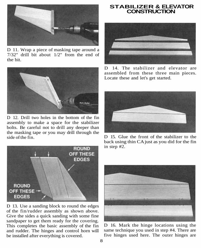
D 14. The stabilizer and elevator areassembled from these three main pieces.Locate these and let's get started.
D 15. Glue the front of the stabilizer to theback using thin CA just as you did for the finin step #2.
D 16. Mark the hinge locations using thesame technique you used in step #4. There arefive hinges used here. The outer hinges are
8

approximately 1" from the edge. The middlehinge is in the center and the other two hingesare centered between the outer hinges and themiddle hinge. These hinge locations are notcritical, but proper placement makes it easierto find the slots after the parts are covered.Cut the slots for the hinges and test fit thestabilizer and the elevator together to check forproper alignment between the two parts.
D 17. Use some thick CA to glue the 1/16"plywood doubler in place on the stabilizer. Thisside is now the bottom of the stabilizer. Usea ruler to get this piece centered as close aspossible. Use a drafting triangle or carpenter'ssquare to draw a line perpendicular to thestabilizer trailing edge and through the center ofthe stabilizer to the point where the leadingedges meet.
D 18. Use a pencil and a rubber band to holdthe stabilizer in place as shown in the photo.
Sight down the bottom of the channel and linethe stabilizer up with the channel (using theline you just drew). When you are satisfied withthe alignment, draw a line down both sides ofthe channel on the top of the stabilizer.
D 19. Remove the pencil and rubber band.With the stabilizer centered over the lines, drilltwo 1/8" holes through the stabilizer using theholes in the channel as a guide. The trailingedge of the stabilizer should be slightly pastthe end of the channel.
D 20. Use a sanding block with some finesandpaper to round off the leading edges,trailing edge and the tips as you did for thefin and rudder. Also sand the top and bottomsurfaces smooth. This completes the basicassembly of the stabilizer and elevator. Thecontrol horn and the hinges will be installedafter the tail is covered.
9
WING ASSEMBLYINSTALL THE AILERONS
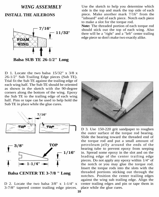
Use the sketch to help you determine whichside is the top and mark the top side of eachpiece. Make another mark 7/16" from the"inboard" end of each piece. Notch each pieceto make a slot for the torque rod.Note: The threaded portion of each torque rodshould stick out the top of each wing. Alsothere will be a "right" and a "left" center trailingedge piece so don't make two exactly alike.
Balsa SUB TE 26-1/2" Long
D 1. Locate the two balsa 15/32" x 3/8 x26-1/2" Sub Trailing Edge pieces (Sub TE).Trial fit the Sub TE against the trailing edge ofeach wing half. The Sub TE should be orientedas shown in the sketch with the 90-degreecorners along the bottom of the wing. Epoxythe Sub TE to the trailing edge of each winghalf. Pins or tape can be used to help hold theSub TE in place while the glue cures.
Balsa CENTER TE 3-7/8 " Long
D 2. Locate the two balsa 3/8" x 1-1/4" x3-7/8" tapered center trailing edge pieces.
D 3. Use 150-220 grit sandpaper to roughenthe outer surface of the torque rod bearing.Slide the bearing toward the threaded end ofthe torque rod and put a small amount ofpetroleum jelly around the ends of thebearing tube to prevent epoxy from seepingin. Spread some epoxy in the slot and on theleading edge of the center trailing edgepieces. Do not apply any epoxy within 1/4" ofthe notch or you may glue the torque rod.Insert the torque rods into the slots with thethreaded portions sticking out through thenotches. Position the center trailing edgesagainst the wing sub trailing edge. Align thecenter trailing edges and pin or tape them inplace while the glue cures.
10

D 4. Epoxy the two 11/32" x 2" x 1-5/8"Tapered TE Supports to the inboard bottom ofeach center trailing edge as shown in the photo.
D 6. Hold the 3/8" x 1-1/4" x 22-1/4" Aileronsin place against the sub trailing edge and underthe torque rods. Mark the location where thetorque rods will enter the ailerons. Drill a 3/32"hole in each aileron to accept the torque rods.
D 5. Use a sanding block with 150-gritsandpaper to sand the inner ends of the subtrailing edge. center trailing edge and thetapered trailing edge to match the angle ofthe foam wing end. Be careful not to changethe angle of the foam wing.
AILERON22-1/2" Long
ARF2W04
D 7. Cut a groove in the leading edge of theaileron to allow clearance for the torque rods.Trial fit the ailerons in place and cut asnecessary until they fit.
D 8. Draw an accurate centerline along theleading edge of the aileron and cut threehinge slots in each aileron. The hinge slotsshould be approximately 1-1/2", 10" and 18"from the wing tip. Place the ailerons againstthe sub trailing edge and mark the hingelocations on the wing. Draw a center linedown the sub trailing edge and cut the hingeslots to match the ailerons.
D 9. Using a sanding block, sand the leadingedge of each aileron to a "V" shape.
11

D 10. Insert the hinges into the slots andtrial fit the ailerons in place on the wing. Donot glue the hinges until after you havecovered the wing. Sand the outboard edge ofthe sub trailing edges and the ailerons tomatch the foam wing tips.
JOIN THE WING PANELS
D 1. Use a sanding block with some fine gritsandpaper (240 - 320 grit) to remove the littlenubs and any mold lines left on the wingfrom the molding process.
D 2. Test fit the 1/8" plywood dihedral joinerin the slots in the wing to make sure it fitsnicely. Mix up about 1/2 oz. of epoxy andspread it throughout the slot in one wingpanel. With the wing panel upside down,insert the joiner in place and squeeze out allthe excess epoxy so that the joiner is flushwith the bottom of the wing (which is facingup). Try to use enough epoxy so that the slotis completely full and level with the surface ofthe wing.
D 3. Lay some wax paper down on the worksurface and mix up one ounce of epoxy.Spread the epoxy throughout the slot and onthe root (middle end) of the other wing panel.Slide the two wing panels together and linethem up as close as possible. Use severalT-pins and masking tape to help hold them inalignment. Flip the wing assembly over so thatthe bottom of the wings are facing up andmake sure that the joiner is seated properly inthe slot. Wipe off any excess epoxy before itstarts to cure. It is important that the wingsare joined with both panels being accuratelyaligned with each other.
D 4. Allow the epoxy from the last step tofully cure.
Note: The tape used in this step is 3/4" widenylon filament reinforcing tape. This isself-adhesive tape with nylon filamentsrunning the length of the tape. It is alsoreferred to as "nylon filament strapping tape,"or "nylon reinforced packaging tape." You canobtain it at any store that sells stationery andpackaging materials or at most hardwarestores. Be sure to use 3/4" wide tape.Narrower tape will not provide the wing with
12

proper reinforcement. Make sure the tape isapplied with no wrinkles and that the stripsare straight and parallel from wingtip towingtip. If this tape is not applied, if it isapplied incorrectly or if a different type oftape is applied, we cannot be responsiblefor any wing failure that may occur.
D 5. Place the wing upside down on the edgeof a table so that only 1/2 of the wing (fromone wing tip to the center joint) is resting onthe table. Starting at the wing tip that isresting on the table, lay a strip of nylon-reinforced strapping tape down so that itcrosses over the center joint directly over thewing joiner.
Press the tape firmly onto the wing and downinto the fillet (where the bottom of the wingmeets the mounting platform) and then flipthe wing around and continue the strip oftape out to the other wing tip. Apply twomore strips of tape between this strip and thetrailing edge of the wing. The fourth stripshould be added between the first strip andthe leading edge of the wing. The previousphoto shows where the strips should belocated. Try to get this tape stuck downas tightly as possible because it adds atremendous amount of strength to the wingwhen properly applied. Make sure you do notchange the washout (twist) or dihedral(V-shape) of the wing when applying the tapestrips. If you are planning on doing someaerobatics or combat with your STURDYBIRDY II, you should also put three strips oftape on the top surface of the wing.
INSTALL THE WING PROTECTOR
D 1. Use a sharp hobby knife or a Dremel®Tool with a tapered cutting bit to trim out theservo and torque rod cut-outs in the PlasticWing Protector. There are scribe lines on thebottom surface of the protector to help guideyou. Trial fit the aileron servo in place andtrim as necessary to make it fit properly. Usescissors or your hobby knife to trim theoutside edges of the wing protector along theremaining scribe lines.
D 2. Place the wing protector on the center ofthe wing so the torque rods fit through theirholes. Draw a line on the wing around theservo cutout. Remove the protector and carveout a hole in the foam wing to fit your servo.Carve out an extra 1/4" square groove in frontand behind the servo cut-out for the servorails. Drill a 1/2" diameter hole for the servowires down through the front edge of the servocutout. Be careful not to cut the plywood wingjoiner when performing these operations.
D 3. Glue the 3/16"x l/4"x 1-1/4" BasswoodServo Rails in place along the front and backedges of the servo cut-out. Put the aileronservo in place and mark on the plasticprotector where the servo mounting screwsshould be. Drill 1/1 6" diameter holes on themarks you just made and mount the servousing the screws provided with your radio.
D 4. Trial fit the wing protector assembly onthe wing and enlarge the cutouts in the foam
13

wing if necessary to make the protector lieflat against the wing. When satisfied withthe fit, remove the servo. Use coarsesandpaper to roughen the bottom of the wingprotector so the glue will hold better. Useepoxy to glue the protector in place.
D 5. Trial fit the ailerons for this step. Mountthe aileron servo with the screws provided inthe radio system and assemble the pushrodsas shown in the sketch above. Attach thepushrods to the torque rods by screwing theAileron Clevis Connector onto the threadedportion of the torque rod. Use a pair of needlenose pliers to make the Z-bends and attachthem to the servo horn. Turn on your radio.plug in your aileron servo and adjust thecentering of the servo horn unti l it iscentered and the right aileron moves upwhen you move the transmitter stick to theright. Adjust the nylon clevis until eachaileron is in a neutral position when thetransmitter sticks and trims are centered.Also adjust the position of the nylon clevisconnector on the torque rod to achieve 7/16"of up and down movement.
COVERING
D 1. The tail surfaces (fin, rudder, stabilizerand elevator) should be covered with one ofthe iron-on coverings to help protect themfrom becoming fuel soaked and ruined. If you
are also going to cover the wing, which willhelp it look nicer longer (and add asmall amount of strength), you can save alittle money by buying only one roll of lowtemperature covering (EconoKote, BlackBaron Film, etc.) and using it for both thewing and the tail surfaces. Otherwise you canuse any type of covering for the tail surfaces,but remember to use a low heat covering forthe wing. A few stripes or your AMA numbercan really add to the looks of your STURDYBIRDY II.
D 2. Follow the instructions that come withthe covering and cover the tail surfaces atthis time. It is a good idea to cover the bottomsurfaces first to get familiar with the coveringsince these surfaces will normally not beseen. When covering the wing, cover rightover the tape and plastic wing protector. Tryto use as little heat as possible.
ATTACHING THE CONTROL HORNS
D 1. Position the nylon control horn on theleft side of the rudder about 1" up from thebottom with the four holes lined up with theleading edge. Use a drop of Thin CA to tackglue the horn in place.
14

D 2. Drill two 3/32" holes through therudder using the control horn as a guide.
D 2. The control surfaces will take someabuse in the learning-to-fly process, so youmust securely glue the hinges in place. Usefour to six drops of CA on each side of thehinge to secure them. Try to get the surfacesas close together as possible, but work thecontrol surfaces back and forth while theglue is curing to make sure they work freelywithout binding. Also, be careful not to gluethe two surfaces together.
D 3. Secure the horn to the rudder with two2-56 x 5/8" machine screws. The screwsshould thread into the nylon "nut plate" onthe opposite side of the rudder. Although notnecessary, you may use some wire cutters oran abrasive cutoff wheel to cut the screws offeven with the plate.
D 4. The other control horn should beinstalled on the top surface of the elevatorabout 1" to the right of the centerline. Followthe same procedure for installing thiscontrol horn.
INSTALLING THE HINGES
D 1. After covering the tail surfaces and thewing, the hinges can be installed. Use yourhobby knife to find the slots you cut earlierand make slits in the covering so you canpush the hinges into place and trial fit thepieces together again. (Refer to the CA hingesection on page 6.)
FUSELAGE CONSTRUCTION
D 1. Locate the 3/8" plywoodfirewall doubler and roundoff the corners with asanding block. Test fit thedoubler into the front of theplastic fuselage tube asshown above. The firewalldoubler should fit into thefuselage with a snug but nottight fit. The front of thefuselage is cut at a slightangle so the firewall and thusthe engine will point down slightly. Becauseof this angle the top and bottom edges of thefirewall doubler are also cut at a slight angle.Make sure you install the firewall doubler soall of its sides match up nicely with the sidesof the fuselage as shown in the sketch.
FIREWALL DOUBLER
15

D 2. The 3/8" plywood firewall doubler isnow glued to the 1/4" plywood firewall front.Use either Thick CA or epoxy and make surethat the front of the firewall doubler iscentered on the back of the firewall. Wipeaway all excess glue that squeezes out.
Tick marks for alignment
Determine where the mount should beinstalled on the firewall. Use the template inthe left column to make it easy to locate themounting holes. Photocopy or cut out thetemplate and tape it in place on the firewall.Poke a T-pin though the template toaccurately mark the bolt locations on thefirewall. Drill a 1/8" diameter hole at the fourpin holes and install the mount using 4-40bolts, #4 flat washers and 4-40 blind nuts.The length of the bolts will be determined bythe thickness of the firewall. A 1/4" firewallwill usually require 7/8" long bolts. Do nottighten the bolts all the way yet.
D 3. Cut or break the "spreader bar" off eachmount half. Carefully trim any extra plastic offeach mount half left by the spreader bar. Thesurfaces where the spreader bars were attachedneed to be very smooth to allow the mounthalves to fit together. Also trim the flashing offany other rough edges. Snap the two mounthalves together as shown in the sketch.
Slide the mount halves apart until the enginemounting lugs will sit flat on the beams.Adjust the mount until the firewall centerline(or offset line) is centered between the "tick"marks on the mount. Tighten the 4-40 boltsto hold the mount halves in position.Determine how far forward the engine shouldbe positioned on the beams and mark whereto drill the mounting holes. Remove theengine and drill a 3/32" hole at each mark.Put a drop of oil in each hole and install theengine using the #4 x 5/8" screws provided.If you prefer to use 4-40 machine screws (notincluded) to install your engine, just tap theholes you drilled with a 4-40 tap.
With the engine installed on the mount, markthe location for the throttle pushrod and fuellines. Remove the engine and mount. Drill a3/16" hole in the firewall for the throttle andtwo 7/32" holes for the fuel and vent lines.
16

end of the channel. Square battery packs fitnicely but most flat packs will also fit. Justtape them flat onto the channel. The batteryshould protrude approximately 1/8" past theend of the channel to keep the fuel tank fromrubbing against the end of the channel.
D 4. Use a small piece of coarse sandpaperto scuff up the inner floor of the aluminumchannel in the area around the front 11/64"bolt hole.
D 5. Insert one of the 8-32 x 1/2" machinescrews into the hole so that it sticks out thebottom of the channel and glue it in placewith plenty of thick C A or epoxy. This screwwill be covered by the battery pack,prohibiting a screwdriver from being used tokeep it from turning. Glue it securely, but becareful not to get any glue on the threads.
D 6. Use some nylon reinforced strapping tapeto securely hold the battery pack on the front
D 7. The servos are "press fit" into thealuminum channel and then held in place withnylon strapping tape. Standard size servosshould fit very nicely and smaller servos can beheld in place by using a piece of wood to fill thespace between the servo sides and the channel.Large servos will not work in the STURDYBIRDY II. The servos should be placed as farforward in the channel as possible and rightnext to each other, but do not overlap the servomounting lugs. The front two servos should bemounted with their servo output shaftstowards the back of the plane and the backservo should have its output shaft towards thefront of the plane. The servo wires should berouted out to the side of the servo withoutgoing under any servos. Wrap two layers ofnylon strapping tape all the way around eachservo and the aluminum channel to hold it inplace. Hook up the entire radio system andturn it on (see the instructions included withyour radio). Adjust the transmitter trims sothey are in the middle of their slots.
17
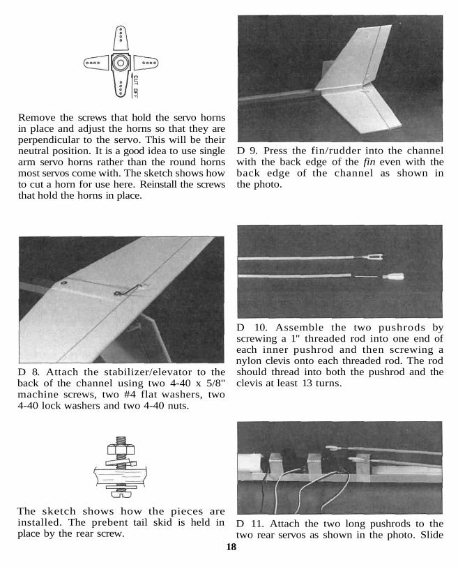
Remove the screws that hold the servo hornsin place and adjust the horns so that they areperpendicular to the servo. This will be theirneutral position. It is a good idea to use singlearm servo horns rather than the round hornsmost servos come with. The sketch shows howto cut a horn for use here. Reinstall the screwsthat hold the horns in place.
D 9. Press the fin/rudder into the channelwith the back edge of the fin even with theback edge of the channel as shown inthe photo.
D 8. Attach the stabilizer/elevator to theback of the channel using two 4-40 x 5/8"machine screws, two #4 flat washers, two4-40 lock washers and two 4-40 nuts.
D 10. Assemble the two pushrods byscrewing a 1" threaded rod into one end ofeach inner pushrod and then screwing anylon clevis onto each threaded rod. The rodshould thread into both the pushrod and theclevis at least 13 turns.
The sketch shows how the pieces areinstalled. The prebent tail skid is held inplace by the rear screw.
D 11. Attach the two long pushrods to thetwo rear servos as shown in the photo. Slide
18
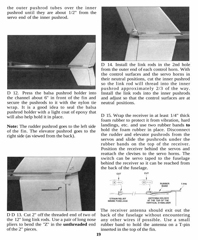
the outer pushrod tubes over the innerpushrod until they are about 1/2" from theservo end of the inner pushrod.
D 12. Press the balsa pushrod holder intothe channel about 6" in front of the fin andsecure the pushrods to it with the nylon tiewrap. It is a good idea to seal the balsapushrod holder with a light coat of epoxy thatwill also help hold it in place.
Note: The rudder pushrod goes to the left sideof the fin. The elevator pushrod goes to theright side (as viewed from the back).
D D 13. Cut 2" off the threaded end of two ofthe 12" long link rods. Use a pair of long nosepliers to bend the "Z" in the unthreaded endof the 2" pieces.
D 14. Install the link rods in the 2nd holefrom the outer end of each control horn. Withthe control surfaces and the servo horns intheir neutral positions, cut the inner pushrodso the link rod will thread into the innerpushrod approximately 2/3 of the way.Install the link rods into the inner pushrodsand adjust so that the control surfaces are atneutral positions.
D 15. Wrap the receiver in at least 1/4" thickfoam rubber to protect it from vibration, hardlandings, etc. and use two rubber bands tohold the foam rubber in place. Disconnectthe rudder and elevator pushrods from theservos and slide the pushrods under therubber bands on the top of the receiver.Position the receiver behind the servos andreattach the clevises to the servo horns. Theswitch can be servo taped to the fuselagebehind the receiver so it can be reached fromthe back of the fuselage.
The receiver antenna should exit out theback of the fuselage without encounteringany other wires if possible. Use a smallrubber band to hold the antenna on a T-pininserted in the top of the fin.
19
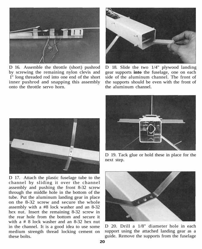
D 16. Assemble the throttle (short) pushrodby screwing the remaining nylon clevis and1" long threaded rod into one end of the shortinner pushrod and snapping this assemblyonto the throttle servo horn.
D 18. Slide the two 1/4" plywood landinggear supports into the fuselage, one on eachside of the aluminum channel. The front ofthe supports should be even with the front ofthe aluminum channel.
D 17. Attach the plastic fuselage tube to thechannel by sliding it over the channelassembly and pushing the front 8-32 screwthrough the middle hole in the bottom of thetube. Put the aluminum landing gear in placeon the 8-32 screw and secure the wholeassembly with a #8 lock washer and an 8-32hex nut. Insert the remaining 8-32 screw inthe rear hole from the bottom and secure itwith a # 8 lock washer and an 8-32 hex nutin the channel. It is a good idea to use somemedium strength thread locking cement onthese bolts.
D 19. Tack glue or hold these in place for thenext step.
D 20. Drill a 1/8" diameter hole in eachsupport using the attached landing gear as aguide. Remove the supports from the fuselage
20

and enlarge the holes to 5/32". Insert a 4-40blind nut in each hole and use a hammer toseat the blind nut in place. Replace thesupports into the fuselage with the blind nutfacing up and use the 4-40 x 5/8" machinescrews to hold everything together.
D 21. Assemble your fuel tank according tothe manufacturer's instructions. Connect thefuel tank to the engine by routing the fueltubing through the two holes in the middle ofthe engine mount and attaching the pickupline to the carburetor and the vent line to thepressure tap on the muffler. Make the fuellines long enough so that there is a 1" gapbetween the fuel tank and the back of thefirewall. Also make sure that the fuel linesare not kinked.
D 22. Slide the whole engine assembly intoplace in the front of the fuselage with thethrottle pushrod extending through the hole inthe firewall. Cut the outer pushrod so it startsabout 1/2" from the 1" threaded rod and
extends about 1/4" past the front of thefirewall. Remove the engine assembly from thefuselage and glue the outer pushrod in place.
D 23. Reinstall the engine assembly into thefuselage. Push two 1/4" x 3-1/2" dowels intoplace in the four holes at the front of thefuselage. The dowels should be a nice, tightfit. If they are too tight you can enlarge theholes slightly with your hobby knife. If theyare too loose you can use a drop of glue tohold them in place. Do not use very muchglue on the front dowels since you will needto remove the dowels to get the fuel tank outof the fuselage. Secure the engine assemblyto the fuselage with four #62 or #64 rubberbands as shown in the next photo.Note: There are eight #2 x 3/8" sheet metalscrews provided if you would rather screwthe firewall in place instead of using therubber bands to hold it on. Tests have shownthat the rubber bands work extremely welland help eliminate damage to the front endduring crashes.
D 24. Cut the inner pushrod to length and cutand install the remaining 1" threaded link rodto hook up the throttle control. Make sure youcan achieve both full throttle and idle withoutbinding of any kind. It is also nice if you canshut the engine off at low throttle and fulldown throttle trim. Bend the link rod ifnecessary to make this possible. The entireengine / fuel tank assembly can be removed atany time by simply removing the rubber
21

bands, the throttle clevis from the servo hornand the two front dowels. This makesadjustments and checking of the fuel systemquick and easy.
D 25. Each wheel axle is made up using a6-32 x 1-1/2" machine screw, two 6-32 hexnuts and two #6 washers. The sketch aboveshows how these parts are assembled. It is avery good idea to use some medium strengththread locking cement between the screw andthe hex nuts. Also make sure that the wheelcan turn freely.
D 26. Slide the two 1/4" x 3-1/2" wingdowels into their holes in the fuselage.Secure with a few drops of CA.
B. The rudder moves to the right when theleft transmitter stick is moved to theright (looking at the plane from the rear).
C. The throttle is closed almost all the waywhen the left transmitter stick is down(back) and is open completely when thestick is up (forward).
ELEVATOR MOVES UP
RIGHT AILERON MOVES UP
LEFT AILERON MOVES DOWN
RUDDER MOVES RIGHT
CARBURETOR WIDE OPEN
4-CHANNEL RADIO SETUP(STANDARD MODE 2)
FINAL ASSEMBLY
D 1. With the fin positioned correctly, applya few drops of thin CA around the base tohold it in place. This type of gluing methodwill keep the fin/ rudder in place unless theplane is crashed pretty hard, in which casethe fin will come out of the channel, usuallywithout breaking.
D 2. Turn the radio system on and adjust allof the trims on the transmitter so that theyare in the middle of their slots.
D 3. Check the following:A. The elevator moves up when the right
transmitter stick is moved down (back).
D 4. Check to make sure that the tail controlsurfaces are in a neutral (straight) positionand the servo arms are perpendicular to thealuminum channel when the transmitter stickis at neutral. Also check the control throws onthe tail surface. You should be able to movethe rudder 3/4" both directions and theelevator should move 1/2" both directions.This should give you a plane that is fairlyresponsive but not too radical.
D 5. Install the second nylon tie wraparound the aluminum channel and thepushrods right in front of the tail surfaces.This will help keep the control surfacesfrom fluttering.
22

BALANCING
With the wing rubber banded to the fuselage,the fuel tank empty and everything else in itsplace, lift the model by placing one finger-tipon the bottom of each wing at theapproximate location of each end of the wingjoiner which is 3" back from the leading edge.The STURDY BIRDY II should hang justslightly nose down or level. If the plane hangswith the nose pointing up, then you will needto add some weight to the nose of the plane.There are several ways you can add thisweight, including stuffing lead weight aroundthe fuel tank or using one of the heavy propnuts available. Under no circumstancesshould you try to fly the plane if it does notbalance correctly!
GETTING READY TO FLYD Use at least four rubber bands to hold theengine/firewall in place and use eight #64rubber bands to hold the wing in place.
D We recommend that you use a nylonpropeller for your first flights since it will notbreak as easily as wood. Sand the edges of theprop before you use it. The edges of nylon propsare very sharp and should be dulled before use.If a prop is damaged in any way it should bediscarded and a new prop used in its place.
D Be sure to conduct a range test on yourradio system before every flying session. Theinstruction manual that came with yourradio should explain how to properly do this.
D If you are using a new engine in yourplane, break it in on the ground according tothe manufacturer 's instructions beforeattempting to fly the plane.
D Never try to start the engine by flipping itover with your finger. Always use either anelectric starter or a "Chicken Stick."
D Always adjust the needle valve on theengine from the back of the plane. Never reachover a rotating prop! Treat these engines withthe utmost respect, they are not toys!
D After each flight, check the propeller,engine bolts, control surfaces, controllinkages, hinges and rubber bands fordamage or looseness and correct ifnecessary. An once of prevention here willkeep you happily flying longer.
FLYINGThe STURDY BIRDY II is a very stable Hyingairplane with a unique self-recovery systemdesigned into it. This makes it one of theeasiest flying planes available. However, it ishighly recommended that you consult anexperienced pilot to help trim out the planeand help you with your first flights. The mostimportant thing to remember when learningto fly is that you need to be able to relate tothe control inputs as if you were sitting inthe plane. If you don't, it will seem like therudder is working backwards when the planeis flying towards you. It may also seem alittle strange that you pull the stick down(back) in order to make the plane go up, butthis is how it works in real planes. It is agood idea to keep facing the same directionthat the model is flying.
The STURDY BIRDY II should be handlaunched into the wind for your first flights.Have a helper hold the plane firmly behindthe landing gear with the wings level whileyou check the controls. Advance the throttleto full throttle. Your helper should then takea few running steps and let the plane fly outof his hand with a slight push (being carefulto keep the wings level). A strong throw is notnecessary. Be prepared to make any initialadjustments to keep the plane climbingslightly and flying straight. Your controlinputs should be very gentle until the planehas climbed high enough to be out of danger
23

of hitting any ground based objects(especially the ground). Once you havereached a safe altitude, trim the plane forstraight and level flight with the enginerunning about half throt t le . If you getdisoriented or the plane does not seem to bedoing what you think it should, just releasethe control sticks and the plane will rightitself. If you see that the plane is heading fordanger which you can not prevent, reducethe throttle to idle and pull the elevator stickback (up elevator) to reduce the impactspeed. When the plane banks into a turn, itis normal for the nose to drop down so beprepared to put in a little up elevator to keepit flying level.
Once you are familiar with how the STURDYBIRDY II handles under power, pull thethrottle back to near idle and slow the planedown. Be sure to do this at a safe altitude! Feedin up elevator to try to keep the plane flying atthe same altitude. If the plane stalls (falls off toone side abruptly) just release the controlsticks, advance the throttle to at least 1/2 andgently pull in some up elevator. Try todetermine the slowest speed the plane will fly atand remember that you need to stay above thatspeed when landing and taking off to avoid astall. If you find the plane getting too high andit is hard to determine what it is doing, reducethe throttle to idle and be patient. The STURDYBIRDY II will lose altitude fairly quickly andyou can resume control.
When preparing to land it is a good idea tomake several practice passes from a safealtitude and gradually get lower until you feelcomfortable with your approach. Then on oneof your next passes, just decrease thethrottle and the plane will land by itself.Landing is really not very tricky if you justconcentrate on guiding the plane with therudder where you want it to go and let itsettle to the ground. Of course it helps to flyat a field that is big enough so you don't haveto worry about where you need to land.
The STURDY BIRDY II also handles verynicely on the ground despite the fact that itis a tail dragger without a steerable tallwheel. When taxiing in grass, hold in upelevator until the plane is moving pretty wellto help keep it from nosing over. To steer themodel when it is moving slow, throw in fullrudder and use bursts of throttle to move theplane around.
REPAIRING
The STURDY BIRDY II is very tough, butthere may be crashes hard enough to breakparts of the plane. The fuselage should notbe repaired. It is inexpensive and very easyand quick to replace. Due to the nature ofplastic, it is very hard to properly mend ifcracked or broken. It should be replaced forsafety reasons.
The foam wing will really take a beating andsurvive. Small dents and dings can beremoved by patching or reheating thecovering material. A broken wing can bequickly repaired with epoxy, but check thenylon tape and replace it if needed. If thewings get bent you can straighten them bybending them the opposite direction andadding a couple more strips of strappingtape. It is important that the wings are keptin their original configuration with themolded-in washout (wing twist). This givesthe STURDY BIRDY II its exceptionalrecovery characteristics.
The tail surfaces can be repaired with CAglues, or new surfaces can be cut from 1/4"balsa available from your local hobby shop.
If dirt gets into the carburetor or onto the engineit should be cleaned off before it has a chance toget inside the engine and cause damage.
Good Luck and Happy Flying!