instruction manual - studebaker golden hawk1956goldenhawk.com/manuals/overdriv.pdf · instruction...
TRANSCRIPT

INSTRUCTION MANUAL
THE WARNER AUTOMATIC
OVERDRIVEFOREWORD
Material contained in this Instruction Manualrelates only to post-war Overdrive types (WarnerR-10 and R-11) as used on the following makes ofcars:
Ford Mercury Frazer Nash Hudson Packard Kaiser Studebaker Lincoln Chevrolet Willys
While the actual details of construction may differamong the different car makes and models, theessential working parts are similar, if not identical,and the information contained herein may beconsidered generally applicable to all carsequipped with these types of Overdrive Units.

TABLE OF CONTENTS
I PERFORMANCE ...................................................................... 2-3 1. General .................................................................................... 2 2. Comfort .................................................................................... 2 3. Operating Economy ........................................................ 2 4. Reduced Engine Maintenance .......................................... 3 5. IncrecLsed Ease of Handling .......................................... 3 6. Highway Driving ...................................................................... 3 7. City Traffic Driving ........................................................ 3 8. Reduced Use of Clutch Pedal ........................................................ 3
II OPERATING PRINCIPLES -. .......................................... 4-8 A. MECHANICAL ........................................................ 4 9. General ...................................................................... 4 10. Free-wheeling Direct Drive .......................................... 4 11. Overdrive ...................................................................... 4 12. Driver-controlled Downshift (Kickdown) ............................ 5 13. Conventional Drive ........................................................ 6 B. ELECTRICAL ...................................................................... 6 14. General ...................................................................... 6 15. Speed-Controlled Operation .......................................... 6 16. Driver-controlled Operation .......................................... 7 17. Locked-out Operation ........................................................ 8III SERVICE OPERATIONS .......................................... 8-15A. TRACING AND CORRECTION OF ELECTRICAL CONTROL TROUBLES .......................................... 8 18. Overdrive Does Not Engage .......................................... 8 19. Overdrive Does Not Release .......................................... 8 20. Will Not Kickdown from Overdrive .......................................... 9 21. Engine Cuts Out When Kickdown is Attempted .............. 9B. MECHANICAL FAULTS ........................................................ 9 22. Dash Control Improperly Connected ............................ 9 23. Transmission and overdrive Improperly Aligned ..............10 24. Improper Reverse Control Parts ............................10 25. Throttle Switch Improperly Adjusted ............................10 26. Improper Installation of Solenoid ............................10 27. Improper Positicrning of Blocker Ring ............................10 28. Insufficient Blocker Ring Friction ..........................................11 29. Damaged Roller Clutch Parts .........................................11C. COMMON CAUSES OF TROUBLE ............................11 30. Does Not Drive Unless Locked Up ............................11 31. Overdive Does Not Engage ............................11 32. Overdrive Does Not Release ............................11 33. Does Not Kickdown from Overdrive ............................11 34. Engine Cuts Out When Kickdown is Attempted ...............11 35. Does Not Release Lockup ..........................................11D. SERVICING OF OVERDRIVE UNIT ..............11 36. General ......................................................................11 37. Disassembly ......................................................................12 38. Cleaning and Inspection ........................................................14 39. Reassembly ......................................................................14 40. Lubrication ......................................................................15

Figure 2.Exploded View of Overdrive Parts
1. Transmission Main Shaft. 2. Snap Ring, Large. 3. Main Shaft Rear Bearing. 4. Snap Ring, Small. 5. Oil Baffle. 6. Adapter Plate Gasket. 7. Adapter Plate. 8. Sun Gear Control Plate and Blocker Ring. 9. Retainer Plate with Oil Cuff. 10. Adapter Snap Ring. 11. Sun Gear Snap Ring.12. Sun Gear. 13. Pinion Cage. 14. Cage Retaining Clip.15. Clutch Cam. 16. Roller Cage Spring.17. Clutch Rollers.18. Roller Cage. 19. Cam Retaining Clip.20. Retractor Spring. 21. Manual Control Shift Rail.22. Manual Control Shaft 23. Manual Control Shaft Oil Seal.24. Manual Control Lever. 25. Manual Control Fork Spring.26. Manual Control Fork Washer
27. Manual Control Fork28. Sun Gear Shift Collar.29. Pawl. 30. Pawl Rod Oil Seal.31. Solenoid. 32. Ring Gear. 33. Output Shaft with Clutch Outer Race.34. Ring Gear Snap Ring. 35. Output Shaft Bearing, Front.36. Housing Gasket.37. Housing. 38. Capscrew.39. Governor. 40. Governor Pinion Snap Ring.41. Governor Pinion. 42. Governor Drive Gear. 43. Speedometer Drive Gear.44. Snap Ring. 45. Output Shaft Bearing, Rear.46. Rear Oil Seal. 47. Universal Joint Flange.48. Plain Washer. 49. Lock Washer.50. Nut. 51. Lockout Switch Gasket.52. Lockout Switch.
I PERFORMANCE
1. GENERAL
a. Since the Warner overdrive was firstintroduced to the public in 1934, over two millionof these units have been produced, more thantwice as many as the combined total of all othercomparable devices offered since the firstautomobile transmission was invented.Considering that each overdrive unit was boughtat substantial extra cost, without aggressive saleseffort in its behalf, and, until recently, withoutadvertising effort, the inescapable conclusion isthat its favorable public reception has been basedsolely upon the merits of its performance. Thatperformance is readily apparent to theexperienced car owner, who recognizes certainsubstantial improvements, not otherwiseobtainable, that the device makes possible in theoverall operation and performance, cmd hence inthe enjoyment, of the car as a whole. While thereis a prevailing tendency to stress "features" assuch, the car owner is primarily interested in theoverall satisfactions of car ownership; a "feature"is useful only to the extent that it makes asubstantial contribution to those satisfactions ofcomfortable, economical and reliable motoring.While the owners of overdrive-equipped cars are,in general, well acquainted with the improvementsthat they enjoy in such satisfactions, few knowexactly why the overdrive brings these benefits tothem, and a brief statement of the fundamentalreasons is in order:
b. If it were not for certain basic limitations of theinternal combustion engine, there would be noneed for the transmission or any of its associatedparts. The reasons for these units arewell-established, and generally understood. Theclutch or its equivalent must he provided becausethe engine must be first started and running,without load, and then. gradually connected to thestanding car. Likewise, the usual first and secondgears, or their equivalent, must provide specialmechanical advantage for the engine whichcannot of itself provide the additional pullingcapacity required for starting, severehill-climbing, or the like. However, suchconditions actually account for a very smallfraction of the car's actual use. Most of the car'stotal mileage is for straightaway driving, whetherin city traffic or upon the open road. For theseconditions the driver habitually uses third speed,or high -gear, for which use the car manufacturerestablishes the relation of engine speed to carspeed by choice of the rear axle gear ratio. Tomeet American standards of performance, a rearaxle gear ratio is chosen, that, on a typical currentmodel car, may yield a power reserve five times
as great as the power required for steady driving,at 40 mph. This reserve for acceleration andhill-climbing, is available by merely pressing theaccelerator; it obviously cannot be used for anyimportant percentage of the total mileage traveled.For most of this total mileage only a relativelysmall percentage of the engine's total ability isused; and the necessity for ready availability ofthe balance results in certain serious compromisesin the overall satisfactions of motor carownership, not generally realized by car ownerswho have been accustomed to accept them. Theseare:
2. COMFORT.
a. In spite of its high level of mechanicalexcellence, the best automobile engine producesnoise, together with some vibration, and theseeffects increase sharply as the engine speedincreases. Whereas, below 30 mph, they may bescarcely noticeable, above 60 mph, they are, to cicritical driver, intolerable in even the best of thecurrent cars without overdrive, Even though thisis somewhat offset by the presence of lessirritating noise from the wind and road, it is wellrecognized that power plant noise and vibrationare major contributors to driver and passengerfatigue, to an extent which can be appreciatedonly by comparison with a car from which theyhave been substantially eliminated.
b. If, for instance, the engine speed can bereduced by 30%, the powerplant noise andvibration is reduced to half, or less. With thisreduction, these unpleasant effects apparentlydisappear, and the riding sensation is almost thatof continuously coasting downhill. To accomplishthis in a manner acceptable to American standardsof performance and handling ease, requires anadditional driving ratio, automatically availableabove slow traffic speeds, in which the car can bedriven for -miles at a time, and from which than'.driver, at his own pleasure, can return to the usual"high gear" for purposes of acceleration andhill-climbing. This, in brief, is what the overdriveprovides.
3. OPERATING ECONOMY.
a. When the car owner buys gasoline, he may beunder the impression that it is for the purpose ofdriving only the car. He seldom realizes that asubstantial portion of it is to overcome enginefriction and drive the engine accessories. At 40rnph, it requires 12 hp. to drive a typical car, butwithout overdrive it requires an additional 18 hp toovercome the powerplcmt losses. On the other
hand, with overdrive these losses amount to onlyI I hp. In the first case gasoline must be bought fora total of 30 hp; in the second case, for a total of23 hp. The difference stays in the owner's pocket.Likewise, the reduced piston speed, as well as thereduced total piston travel, enables manyoverdrive-equipped cars to run from one oilchange to the next without adding oil.
4. REDUCED ENGINE MAINTENANCE.
a. While it is obvious that if the engine travels only0.7, as far as the car, the intervals betweenthe-customary engine repair and service operationswill be proportionately extended, it must not beoverlooked that the engine also travels only 0.7 asfast, with overdrive operation, and this reductionof destructive forces serves to extend theseintervals still further. Especially among thoseowners accustomed to hard, fast driving, thisreduction of engine maintenance is a commonexperience with overdrive-equipped cars.
The buyer of a now car has a choice of many itemsof extra equipment that add to the pleasure andconvenience of motoring, but the overdrive is theONLY one that pays back its own extra cost by itssavings. The luxury of increased con-dort andimproved performance that it gives is FREE.
5. INCREASED EASE OF HANDLING.
a. When a car is equipped with two driving ratios.one for comfortable and economical travel and theother for high activity, or acceleration, it may beexpected that these two ratios will be used to drivethe car for all but an insignificant part of the car'stotal mileage. The constantly changing conditionsof road and traffic will re .quirefrequent changing from one ratio to the other andmodem driving conditions require that thesechanges be made by controls that relieve the driverof effort and attention; the right thing must be doneat the right time. Having these changes dictated bythe fixed routine of an automatic mechanism is notenough. The device must also comply with theintentions of the driver-it must actually anticipatehis requirements. The overdrive controls fulfillthese needs as follows:
6. HIGHWAY DRIVING.
a. When the car is operated below a predetermined1. cut-in" speed, varying from 20 to 32 mph,according to car make and model, the direct driveis used, making available the acceleration sodesirable at lower speeds. As the car speedincreases above the cut-in point the overdrive unitwill shift-into the overdrive ratio, but only whenthe driver desires no further acceleration; whenconsciously, or unconsciously, he lifts his lootfrom the accelerator, whereupon the shift is
completed. Thereafter, the overdrive remains ineffect until the car speed falls below the "cut-out"point, when the overdrive is released.
b. However, at high speeds, the driver whileoperating in overdrive may require additionalacceleration, beyond that available by opening thethrottle wide. His natural impulse is to press theaccelerator further, and this act releases theoverdrive, making available the full acceleration ofdirect drive, The direct drive is retained as long asthe full acceleration is required; when the driver nolonger requires it he unconsciously lifts his footfrom the accelerator, whereupon the overdrive isresumed. If the driver so desires, he may retain thedirect drive indefinitely by maintaining a smallamount of throttle opening. By thus combining theunconscious reflexes of the driver with theautomatic mechanism of the overdrive unit, it ispossible to endow a mechanical "brain" with"judgment", and still have the entire action subjectto the conscious control of a skilled driver.
7. CITY TRAFFIC DRIVING.
a. Much city driving is under conditions whichpermit speeds of 20-32 mph, with frequent stops.Many drivers are accustomed to start in secondgear under such condi t ions . Wi thoverclrive-equipped cars, the driver may start insecond gear, accelerate up to the cut-in speed, and,by merely lifting the foot from the acceleratorpedal, engage the overdrive-second gearcombination, which is approximately the sameratio as the usual third speed. At the first trafficstop, it is merely necessary to release the clutch;the gearshift lever is not touched. Furthermore, ifa special burst of acceleration is needed in a tighttraffic spot, the full power of second gear may behad by pressing the accelerator to the floor,resuming the overcirive-second by the usualmethod of closing the throttle. Most of the benefitsof automatic gearshifting are thus had without theusual complicated and expensive automatictransmission mechanism.
8. REDUCED USE OF CLUTCH PEDAL
a. At speeds below the overdrive cut-in point; thefree-wheeling action of the overdrive unit makes itpossible to do all gearshifting without releasing themain clutch. Above cut-in speed, it is necessary torelease the clutch for shifting gears, and likewise,the clutch must be released when the car is beingstarted from standstill, and whenever it is beingbrought to a stop.

Figure 3
Figure 4
II OPERATING PRINCIPLES A. MECHANICAL
9. GENERAL
a. The current production types (Warner R-10 andR-11) of overdrive units are similar, the R-10being used on the smaller engines, and the R-11on the larger engines, Variations of these units aremade to adapt them to the various makes andmodels of cars, but the principal working parts ofboth types are similar, if not identical, in allvariations. Therefore the working parts shown incut-away assembly (Figs. 1, 3, 5, & 8), and inexploded view (Fig. 2), are taken as representativeof all current overdrive units, whose mechanicaloperating principles are explained as follows:
10. FREE-WHEELING DIRECT DRIVE.
a. The transmission mainshaft (Figs. 2 and 3)extend thru the sun gear and is splined into thepinion cage and roller clutch cam. The latter has12 cam surfaces, and 12 clutch rollers located
against these surfaces by means of the roller cageand the roller cage spring. When a driving torque
is applied against the cam the rollers are forcedoutward into wedging contact with the outer race(Fig. 4-a), thus driving the car. Under suchdriving conditions, all the overdrive gears andtheir directly-associated control Darts revolvetogether as a unit.
b. On the other hand, if the throttle is closed,removing the driving force, the rollers releasetheir wedging contact (Fig. 4-b), permitting theroller clutch to overrun, with the mainshaft,pinion cage, and engine turning at ci slower speedthan the ring gear, output shaft, and propellershaft. Under such conditions, the ring gear willturn faster than the pinion cage, and the sun gearwill turn slower than the latter. In fact, the sungear may turn forward, stand still, or turnbackward, depending solely upon the relativespeeds of the transmission main shaft, and theoutput shaft. If the former is turning at exactly70% of the speed of the latter, (72% in the case ofR-11 type units), the sun gear will stand still; if itturns faster than this, relatively, the sun gear willturn forward; and if it turns slower, the sun gearwill turn backward. If the engine is idling with thecar moving forward, this reverse rotation may bequite fast.
11. OVERDRIVE.
a. If the sun gear is held against rotation, (Fig. 5),the pinion cage, and hence, the engine, willrevolve through only 0.7. turn for each turn of the-propeller shaft (Fig. 6). The action of the controlelements involved is as follows:
b. Assuming that the car is being driven with thedash control pushed in (Fig. 3), the sun gear

control plate revolves along with the sun gear atthe speed of the transmission mainshaft. Under such circumstances, the blocker ring, by itsfrictional drag upon the hub of the control plate,is rotated into such a position as to latch thecontrol pawl against inward movement (Fig. 7-a).When the car reaches a predetermined
speed (the "cut-in" speed, which varies between20 and 32 mph, according to car make and model)the governor contacts close, acting through theoverdrive electrical circuit to energize thesolenoid. The latter sets up a spring pressureagainst the pawl, tending to push it intoengagement. Th-is movement is prevented by theblocker. However, the driver, eitherunconsciously, or consciously, and according tohis own choice, may momentarily close thethrottle, whereupon the roller clutch releases, andthe engine slows down. At the same time, the sungear slows down, more rapidly, so that the sungear passes through the stand-still condition whenthe engine speed has fallen 30 %, and thenreverses its motion. Upon the instant of reversal,the blocker ring, moved by its frictional drivefrom the control plate hub, also rotates slightly inthis direction and releases the pawl which snapsinto the first notch of the backwardly-rotatingcontrol plate (Fig. 7-b). The extreme rapidity ofthis action insures that the control plate cannotrotate backward more than 1/3 turn at the most;usually, it will be less. This engagement, at nearlyperfect synchronism, accounts for the smoothaction of this control. Once engaged, under theconditions of normal driving, the overdrive is inaction until the car speed falls to a value 3 or 4mph lower than the cut-in speed, when thegovernor contacts open, releasing the solenoid,which withdraws the pawl (if throttle is closed), whereupon thecondition of free-wheeling direct drive isresumed. 12. DRIVER-CONTROLLED DOWNSHIFT(KICKDOWN)
a. It has been noted, above, that when theoverdrive is engaged, the engine only turns 0.7 asfast a.3 when in direct drive. This reduces thePower available (excepting at high car speeds)and although this reduced power- is usuallysufficient for all purposes, there are times when itis desirable to return to direct drive, for morepower, without reducing the car speed to the pointwhere the overdrive would normally release.
b. Under such circumstances, the driver merelypresses the accelerator pedal beyond thewide-open position. Through suitable electricalcontrols, this releases the solenoid, urging thepawl toward release from the control plate.However, due to the driving torque reaction, thepawl is held, and cannot move to release until thetorque is momentarily relieved. This isaccomplished by interrupting the ignition,whereupon the pawl snaps to release, whichimmediately restores the ignition. When theoverdrive has been thus disengaged the rollerclutch carries the direct drive, and the driver mayhold it in this condition at his pleasure, until hechooses to re-engage overdrive by merely liftinghis foot from the accelerator, momentarily.Thereupon the overdrive is resumed, unless. thecar speed has in the meantime fallen below theoverdrive release point.
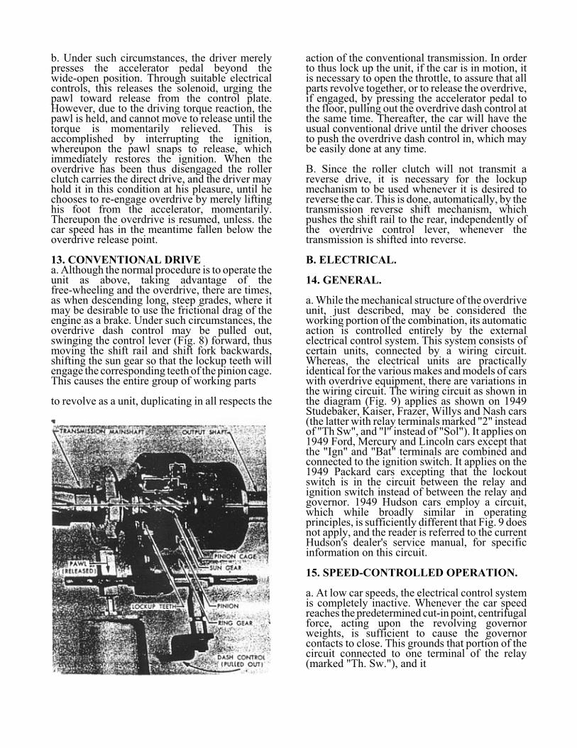
13. CONVENTIONAL DRIVEa. Although the normal procedure is to operate theunit as above, taking advantage of thefree-wheeling and the overdrive, there are times,as when descending long, steep grades, where itmay be desirable to use the frictional drag of theengine as a brake. Under such circumstances, theoverdrive dash control may be pulled out,swinging the control lever (Fig. 8) forward, thusmoving the shift rail and shift fork backwards,shifting the sun gear so that the lockup teeth willengage the corresponding teeth of the pinion cage.This causes the entire group of working parts
to revolve as a unit, duplicating in all respects the
action of the conventional transmission. In orderto thus lock up the unit, if the car is in motion, itis necessary to open the throttle, to assure that allparts revolve together, or to release the overdrive,if engaged, by pressing the accelerator pedal tothe floor, pulling out the overdrive dash control atthe same time. Thereafter, the car will have theusual conventional drive until the driver choosesto push the overdrive dash control in, which maybe easily done at any time.
B. Since the roller clutch will not transmit areverse drive, it is necessary for the lockupmechanism to be used whenever it is desired toreverse the car. This is done, automatically, by thetransmission reverse shift mechanism, whichpushes the shift rail to the rear, independently ofthe overdrive control lever, whenever thetransmission is shifted into reverse.
B. ELECTRICAL.
14. GENERAL.
a. While the mechanical structure of the overdriveunit, just described, may be considered theworking portion of the combination, its automaticaction is controlled entirely by the externalelectrical control system. This system consists ofcertain units, connected by a wiring circuit.Whereas, the electrical units are practicallyidentical for the various makes and models of carswith overdrive equipment, there are variations inthe wiring circuit. The wiring circuit as shown inthe diagram (Fig. 9) applies as shown on 1949Studebaker, Kaiser, Frazer, Willys and Nash cars(the latter with relay terminals marked "2" insteadof "Th Sw", and "l" instead of "Sol"). It applies on1949 Ford, Mercury and Lincoln cars except thatthe "Ign" and "Bat" terminals are combined andconnected to the ignition switch. It applies on the1949 Packard cars excepting that the lockoutswitch is in the circuit between the relay andignition switch instead of between the relay andgovernor. 1949 Hudson cars employ a circuit,which while broadly similar in operatingprinciples, is sufficiently different that Fig. 9 doesnot apply, and the reader is referred to the currentHudson's dealer's service manual, for specificinformation on this circuit.
15. SPEED-CONTROLLED OPERATION.
a. At low car speeds, the electrical control systemis completely inactive. Whenever the car speedreaches the predetermined cut-in point, centrifugalforce, acting upon the revolving governorweights, is sufficient to cause the governorcontacts to close. This grounds that portion of thecircuit connected to one terminal of the relay(marked "Th. Sw."), and it
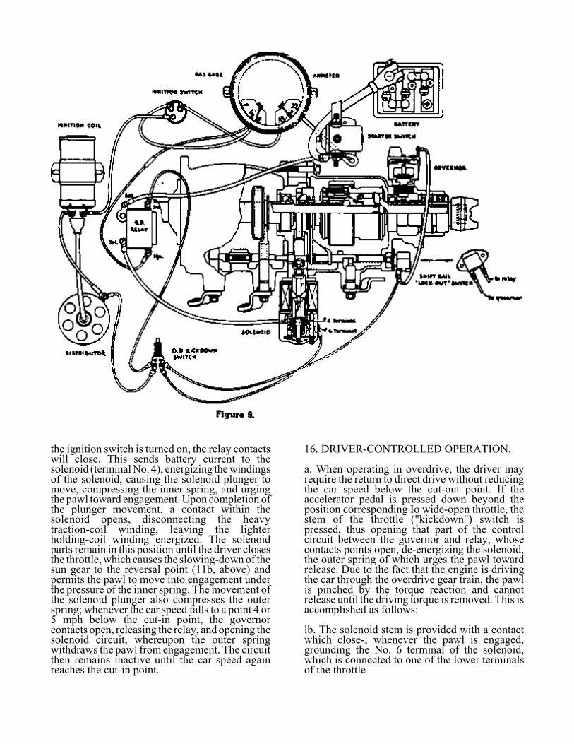
the ignition switch is turned on, the relay contactswill close. This sends battery current to thesolenoid (terminal No. 4), energizing the windingsof the solenoid, causing the solenoid plunger tomove, compressing the inner spring, and urgingthe pawl toward engagement. Upon completion ofthe plunger movement, a contact within thesolenoid opens, disconnecting the heavytraction-coil winding, leaving the lighterholding-coil winding energized. The solenoidparts remain in this position until the driver closesthe throttle, which causes the slowing-down of thesun gear to the reversal point (11b, above) andpermits the pawl to move into engagement underthe pressure of the inner spring. The movement ofthe solenoid plunger also compresses the outerspring; whenever the car speed falls to a point 4 or5 mph below the cut-in point, the governorcontacts open, releasing the relay, and opening thesolenoid circuit, whereupon the outer springwithdraws the pawl from engagement. The circuitthen remains inactive until the car speed againreaches the cut-in point.
16. DRIVER-CONTROLLED OPERATION.
a. When operating in overdrive, the driver mayrequire the return to direct drive without reducingthe car speed below the cut-out point. If theaccelerator pedal is pressed down beyond theposition corresponding Io wide-open throttle, thestem of the throttle ("kickdown") switch ispressed, thus opening that part of the controlcircuit between the governor and relay, whosecontacts points open, de-energizing the solenoid,the outer spring of which urges the pawl towardrelease. Due to the fact that the engine is drivingthe car through the overdrive gear train, the pawlis pinched by the torque reaction and cannotrelease until the driving torque is removed. This isaccomplished as follows:
lb. The solenoid stem is provided with a contactwhich close-; whenever the pawl is engaged,grounding the No. 6 terminal of the solenoid,which is connected to one of the lower terminalsof the throttle

switch; when the latter is moved to open theconnection across its upper terminals, thelower terminals are connected, and thisgrounds the primary breaker of the ignitiondistributor, thus interrupting the enginetorque. The pawl immediately snaps out ofengagement, and this movement opens thegrounding contacts of the solenoid, restoringthe ignition. This entire action occurs withsuch rapidity that not more than 3 or 4cylinder explosions are missed. In the eventthat the driver raises his foot slightly from theaccelerator pedal the normal position of thethrottle switch is restored, thus re-energizingthe solenoid, but the pawl cannot re-engageuntil the throttle is closed to cause the engineto slow down, sufficiently to reverse therotation of
the sun gear, as previously explained.
17. LOCKED-OUT OPERATION.
a. In the event that the overdrive unit isoperated in the locked-out, or conventionaldrive condition, either by having the dashcontrol knob pulled out, or by shifting thetransmission into reverse, the shift rail ismoved to the rear, which also opens thelockout switch. Since this opens the circuitbetween the governor and relay, the lattercannot act to energize the solenoid. Thisprevents any possible attempt to engage thepawl when operating in either conventionaldrive or reverse.
III SERVICE OPERATIONS A. TRACING AND CORRECTION OF ELECTRICAL CONTROL TROUBLES.
18. OVERDRIVE DOES NOT ENGAGE.
a. Turn on ignition switch.
b. Ground "Th Sw" terminal of overdrive relay. Ifrelay does not click, inspect relay fuse; replace ifnecessary. If fuse is good, check with 6-volt testlamp at both fuse clips. If lamp does not burn ateither fuse clip, check wiring between relay andbattery or ignition switch. If lamp burns at bothfuse clips, and there is no relay click when "ThSw" terminal is ground(?d, replace relay. 11 relayclicks, but solenoid does not, follow procedure18-1. below. If both relay and solenoid click -
c. Ground the two upper terminals of the throttleswitch in turn. If no click results, it indicatesdefective wire or poor terminal connectionsbetween throttle switch and relay. If click resultsfrom grounding one terminal, but not fromgrounding the other, it indicates open throttleswitch. Before discarding switch, note 25-b.below. 11 click results as the two terminals aregrounded in turn, -
d. Make similar tests at lockout switch, (exceptingon Packard). 11 open switch is indicated, note22-a. below, before, discarding switch. If clickresults as the two terminals are grounded in turn.
e. Ground governor terminal. 11 no click results,it indicates defective wire or terminal connectionsbetween governor and lockout switch (throttleswitch on Packard). If relay clicks, replacegovernor unless-, governor drive pinion is foundto be missing, or governor drive gear is slipping(see 37-k below).
1. If, in following procedure 18-b, above, relayclicks, but solenoid does not, remove wire from"Sol" terminal of relay and replace with test lamp.If latter does not burn when relay clicks, replacerelay. If it does burn, -
g. Replace wire to "Sol" terminal of relay, andremove other end of this wire from No. 4 terminalof solenoid and connect to test lamp. Close relayas before. If lamp does not burn, it indicatesdefective 'Wire. If it does burn, it indicatesdefective solenoid or connections. Removesolenoid cover, examine solenoid contacts, cleanif necessary, reconnect and test again for clicksbefore discarding solenoid.
1 9. OVERDRIVE DOES NOT RELEASE.
CAUTION: IF THIS CONDITIONACTUALLY EXISTS, CAR WILL NOTROLL BACKWARDS, AND ANY ATTEMPTTO FORCE IT TO DO SO MAY SERIOUSLYDAMAGE THE OVERDRIVE UNIT ITSELF.
a. Check for this condition by rolling the carbackward by hand, with the gearshift lever inneutral, ignition switch off. If it will roll forward,but not backward, follow procedure 19-h-i, below.If it will roll backward,-
b. Push overdrive dash control knob in; turnignition switch on and off. 11 overdrive relay andsolenoid do not click, follow procedure 19-h-i,below. If click occurs, it indicates circuit groundbetween relay and governor, or within thegovernor or relay (on Lincoln, Mercury, or Fordcars it may mean, also, that the relay contacts arestuck together);

c. Pull overdrive dash control knob out; turnignition switch on and off. if no click occurs,grounded circuit is indicated between lockoutswitch and governor, or within the governor;follow tracing procedure 19-e, below. If clickoccurs, push dash control knob in;
d. Hold throttle switch open, either by pressingaccelerator to the floor, or by pressing the throttleswitch stem by hand; turn ignition switch on andoff. If no click occurs, grounded circuit isindicated between lockout switch and throttleswitch; follow tracing procedure 19-1, below. Ifclick occurs, ground is indicated between throttleswitch and relay, or within one of these units;follow tracing procedure 19-g, below.
e. With ignition switch turned on and overdrivedash control pushed in, disconnect governor. I,'click occurs, replace governor. If no click occursat governor, replace connection, and disconnectgovernor wire at lockout switch. If click occurs,inspect wire for ground, also switch terminal,which may have been bent into grounding contact.If no click occurs, replace connection, and
f. Disconnect other wire at lockout switch; if clickoccurs, inspect terminal for ground. 11 none isfound, replace switch. If no click occurs,disconnect and reconnect, in turn, the two upperterminals of the throttle switch. If click occurs aseach is disconnected, grounded wire is indicatedbetween lockout switch and throttle switch;
g. 11 click occurs when one terminal, but not theother, of the throttle switch is disconnected, itindicates a ground at the terminals, or within thethrottle switch, in which case it should bereplaced. If no click occurs when either terminal isdisconnected, disconnect wire from "Th Sw"terminal of relay. If click occurs, it indicatesgrounded wire between that point and the throttleswitch.
h. 11 no click occurs, when this wire isdisconnected, but relay still clicks when ignitionswitch is turned on and off, inspect terminal forchips or other ground. If none is found, replacerelay. With "Th Sw" terminal disconnected,disconnect "Sol" terminal. If solenoid clicksreplace relay. If no solenoid click occurs,
i. Remove solenoid. If solenoid can be removedwithout rotating 1/4 turn, it indicates improperinstallation, without properly engaging solenoidstem in pawl (see 26-a-b, below). Removesolenoid cover, and see if stem has been forcedpast upper contact spring. Use pawl pulling tool tocheck pawl for release; if pawl cannot bewithdrawn, freely, from engagement, or if the carcannot be pushed forward by hand, with one of theforward transmission speeds engaged, the unit hasprobably been damaged internally, and must berepaired or replaced. If no such damage is
apparent, and solenoid installation appears properthe solenoid itself may be sticking.
20. WILL NOT KICKDOWN FROMOVERDRIVE
a. Ground No. 6 terminal of the solenoid, withengine running. Press throttle switch stem byhand. If engine stops, inspect connection atterminal, and also contacts inside solenoid forproper closing when stem is extended. If enginedoes not stop, it should stop when one of the lowerterminals of the throttle switch is grounded. Whenthe other terminal is grounded engine should stopwhen the throttle switch stem is pressed. If it doesnot, replace switch. If the engine does not stopwhen either of the terminals is grounded, wire orconnections are defective, between the throttleswitch and the primary terminal of the ignitiondistributor. (On some: cars this connection is madeto one of the primary terminals of the ignition coil;be sure that it is not made to the terminalconnected to the ignition switch.)
b. Occasionally, the upper contacts of the throttleswitch will not open, To test for this condition,turn on ignition switch, ground at lockout switchor governor; this should cause the solenoid toclick. Press the accelerator pedal all the way to thefloor; this should cause a second click as thesolenoid releases. 11 there is no second click, itindicates a defective throttle switch, or that thethrottle switch is not being opened (see 25-a-b,following).
21. ENGINE CUTS OUT WHEN KICKDOWNIS ATTEMPTED.
a. With engine running, press throttle switch stemwith hand. If engine stops, disconnect wire fromNo. 6 terminal of solenoid and press switch again.If engine does not stop, it indicates a damaged No.6 terminal insulator in the solenoid cover, or adefective solenoid. It the engine stops with thisterminal disconnected, it indicates either agrounded wire, or a defective throttle switch.
B. MECHANICAL FAULTS.
22. DASH CONTROL IMPROPERLYCONNECTED.
a. Unless the overdrive dash control wire isconnected to the lockup lever on the left side ofthe overdrive housing in such a manner as to movethe lever all the way back when the dash controlknob is pushed in, the lockup switch may be heldopen, thus disabling electrical control operation.Likewise, it may hold the shift rail in such aposition as to interlock the pawl against fullengagement, even though the lockout switch is notheld open, resulting in a buzzing noise whenoverdrive engagement is attempted.

b. To correctly make this connection, loosenbinding post at lever, pull dash control knob out1/4 in., move lever all the way to the rear, andtighten binding post.
23. TRANSMISSION AND OVERDRIVEIMPROPERLY ALIGNED.
a. The same symptoms as above may also resultfrom misalignment, at assembly, of the overdrivehousing to the transmission case, resulting inbinding of the overdrive shift rail, so that theretractor spring cannot move the rail fullyforward, when the dash control knob is pushed in,and the transmission is not in reverse. Under suchconditions, the unit may remain fully locked up.
b. To test for this, be sure that the transmission isnot in reverse; disconnect the dash control wirefrom the lockup lever, and feel the lever for freeforward movement. If the lever can he movedforward more than 1/4 in., it indicates thatmisalignment probably exists. To correct this,loosen the capscrews between the overdrivehousing and transmission case, and tap the adapterplate and overdrive housing until a position isfound where the rail shifts freely; tightencapscrews.
24. IMPROPER REVERSE CONTROLPARTS
a. Most overdrive installations provide somearrangement of the transmission controls wherebythe shifting of the transmission into reverse alsomoves the overdrive shift rail backward to lockupthe unit, necessary for reverse drive. This usuallyinvolves some modification of one or more partsof the reverse shifting mechanism, which are notrequired with the conventional transmission.Therefore, if the car will not reverse unless theoverdrive clash control is pulled out, it is anindication that such special parts were omittedfrom the assembly.
25. THROTTLE SWITCH IMPROPERLYADJUSTED.
a. The position of the throttle switch should be soadjusted, by means of the two large nuts whichclamp the switch shank, that the accelerator pedalgives a full movement of the switch before thepedal strikes the floor mat. The throttle controlrod (to the carburetor) should be so adjusted thatthe carburetor throttle lever strikes its full openstop just as the pedal touches the throttle switchstem.
b. Occasionally the large nuts which clamp the
throttle switch through the floor board or switchbracket are tightened sufficiently to bend thethrottle switch shank, thus preventing free motionof the throttle switch stem. This may usually be
remedied by loosening the upper of the two nuts.
26. IMPROPER INSTALLATION OFSOLENOID.
a. If car cannot be rolled backward, under anycircumstances and there is no relay click when theignition is turned on, it probably indicates that thesolenoid has been installed directly, withouttwisting into the bayonet lock between solenoidstem and pawl, thus jamming the pawlpermanently into overdrive engagement.
b. If the car will occasionally roll backwards, butnot always, (and there is no relay click when theignition switch is turned on) it may indicate that,upon installation, the bayonet lock was caught,and the solenoid forcibly twisted into alignmentwith the attaching flange, thus shearing off theinternal keying of the solenoid. Under thesecircumstances, the end of the solenoid stem maynot catch in the pawl, and upon release of thesolenoid, the pawl will not be withdrawnpromptly from engagement, but may simply driftout. 11 the solenoid stem end has its two flatsexactly facing the two solenoid flange holes, itwill not withdraw the pawl properly. If the stemcan be rotated when grasped by n pair of pliers, itinc4cates that the internal keying has beensheared. If it cannot be thus rotated, it may be (inthe case of Ford cars), that the special stationwagon and convertible solenoid has been installedby mistake (this solenoid has the stem flats facedtoward the flange holes).
27. IMPROPER POSITIONING OFBLOCKER RING.
a. Occasionally, either in assembly at the factory,or in service operations in the field, the internalparts of the overdrive unit may have been rotatedwith the solenoid removed, and the pawlwithdrawn from its normal location. This maycause the blocker ring to rotate, so that its twolugs are not located with respect to the pawl asshown in Figs. 7 and 21. In other words, the solidportion of the blocker ring may be in alignmentwith the pawl, which will prevent full engagementof the pawl with the sun gear control plate.
b. To test for this condition, remove solenoidcover, pull dash control knob out, roll car 2 ft..forward. Push dash control in, turn ignition switchon. Then ground "Th Sw" terminal of relay, andwatch movement of center stem of solenoid. Itshould not move more than 1/8 in. when thesolenoid clicks. Then, with the relay terminal stillgrounded, shift into low gear, and roll car forwardby hand. Solenoid stem should then move an additional 3/8 in., as the pawl engages fully.These two tests indicate proper blocker action.Unless both tests are met, the blocker ring isprobably not in the correct position.
c. 'Rather than disassemble the entire overdriveunit, this condition may be corrected externally.With transmission in neutral, and the dash controlpulled out, move car forward one full turn of thepropeller shaft. Then, loosen the two solenoidcapscrews as far as possible without removing, andpull solenoid out as far as it will go, and hold itthere while the propeller shaft is turned forwardabout 1/8 turn. Then push solenoid in, and tightencapscrews. The reasons for this procedure arereadily understood from a study of Fig. 7.
28. INSUFFICIENT BLOCKER RINGFRICTION.
a. If the overdrive engages with a severe jolt, ornoise, probably the blocker ring (Fig 21) has lost itsfrictional grip upon the hub of the sun gear controlplate. This grip should be sufficient to set up africtional drag of 4-6 lbs. when new, which will fallto 1-11/2 lbs. when thoroughly broken in. This ismeasured by holding one lug of the control plate ina soft-jawed vise, with a spring balance hooked intothe notch of the nearest blocker lug, and noting thepull required to rotate the blocker after it has startedmoving. While low friction may be corrected bysqueezing the blocker ring together for a tighter fit,new parts should be installed if available.
29. DAMAGED ROLLER CLUTCH PARTS.
a. Occasionally, the unit may not drive the carforward in direct drive, unless locked up by pullingthe dash control. This may be caused by one ormore broken rollers in the roller clutch, the remedyfor which is the replacement of the entire set ofrollers.
b. This may also be caused by sticking of the rollercage upon the cam. This cage must move freely topush the rollers into engaging position, under thepressure of the two actuating springs.
c. Sometimes this is due to slight indentations,worn in the cam faces by the rollers spinning,remedied by replacement of the cam.
C. COMMON CAUSES OF TROUBLE.
30. DOES NOT DRIVE UNLESS LOCKED UP.
a. Broken clutch roller (29-a). b. Roller cage stuck(29-b). c. Clutch cam worn (29-c).
31. OVERDRIVE DOES NOT ENGAGE.
a. Dash control knob not fully pushed in (17-a). b.Fuse blown or missing (18-b). c. Open circuit between governor and relay (18-a to18-g). d. Improperly connected dash control cable (22-a).e. Shift rail bound by housing misalignment (23-a).f. Throttle switch stem stuck (25-b). g. Defective throttle switch (18-c). h. Defective governor (18-e). i. Governor pinion missing (18-e).
j. Defective solenoid (18-g). k. Improperly wired (14-a, Fig. 9). l. Blocker ring not in proper position (27-a).
32. OVERDRIVE DOES NOT RELEASE.
a. Grounded circuit between governor and relay(19-a to 19-h). b. Solenoid improperly installed (19-i. 26-a-b). c. Defective governor (19-e). d. Defective relay (19-h). e. Defective solenoid (19-i). f. Improperly wired (14-a. Fig. 9). g. Defective throttle switch (19-d).
33. DOES NOT KICKDOWN FROMOVERDRIVE.
a. Throttle switch improperly adjusted (25-a). b. Defective throttle switch (20-a). c. Open or missing connection between solenoidNo. 6 terminal and distributor (20-a, Fig. 9).
34. ENGINE CUTS OUT WHEN KICKDOWNIS ATTEMPTED.
a. Defective solenoid (21-a). b. Grounded wire between solenoid No. 6 terminaland throttle switch (21-a). c. Defective throttle switch (21-a).
35. DOES NOT RELEASE LOCKUP.
a. Improperly connected dash control cable (22-a).b. Shift rail bound by housing misalignment (23-a).
D. SERVICING OF OVERDRIVE UNIT.
36. GENERAL. a. The procedure described below, as it relates tothe transmission proper, applies to transmissionsmanufactured by Warner Gear Division, Borg-Warner Corporation. Where the overdrive unit isattached to a transmission made by the carmanufacturer, of a design materially different, suchprocedure must be modified accordingly. In suchcases, the reader is referred to the service manual ofthe car manufacturer.
b. In the following, the text has been prepared toapply to overdrive unit structures that, whileidentical in principle, will vary in some detail fromone make of car to the other. Where no attention iscalled to such variations from the parts arrangementshown in Fig. 2. it is assumed that the procedure ofdisassembly and reassembly is obvious.
37. DISASSEMBLY.
a. Remove transmission and overdrive assemblyfrom the car, and if possible, mount thetransmission on a transmission stand or largebench vise. Drain oil from both transmission andoverdrive cases.
b. Remove front universal joint companion flangefrom overdrive unit, using suitable puller ifnecessary. Do not use a hammer to drive theflange off.
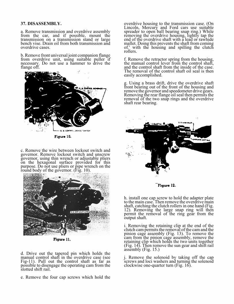
c. Remove the wire between lockout switch andgovernor. Remove lockout switch and unscrewgovernor, using thin wrench or adjustable plierson the hexagonal surface provided for thispurpose. Do not use pliers or pipe wrench on theround body of the governor. (Fig. 10).
d. Drive out the tapered pin which holds themanual control shaft in the overdrive case (seeFig-11). Pull out the control shaft as far aspossible to disengage the operating cam from theslotted shift rail.
e. Remove the four cap screws which hold the
overdrive housing to the transmission case. (OnLincoln, Mercury and Ford cars use suitablespreader to open ball bearing snap ring.) Whileremoving the overdrive housing, lightly tap theend of the overdrive shaft with a lead or rawhidemallet. Doing this prevents the shaft from comingof.' with the housing and spilling the clutchrollers.
f. Remove the retractor spring from the housing,the manual control lever from the control shaft,and the control shaft from the inside of the case.The removal of the control shaft oil seal is theneasily accomplished.
g. Using a brass drift, drive the overdrive shaftfront bearing out of the front of the housing andremove the governor and speedometer drive gears.Removing the rear flange oil seal then permits theremoval of the two snap rings and the overdriveshaft rear bearing.
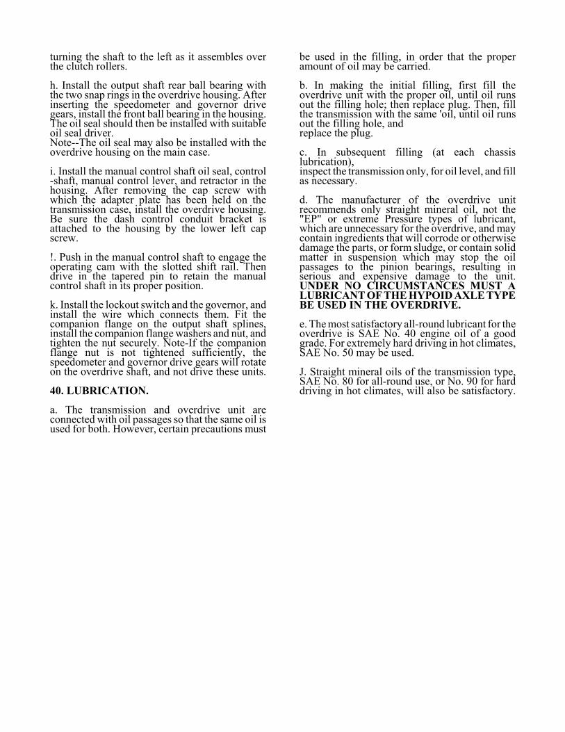
h. install one cap screw to hold the adapter plateto the main case. Then remove the overdrive mainshaft, catching the clutch rollers in one hand (Fig.12). Removing the large snap ring will thenpermit the removal of the ring gear from theoutput shaft.
i. Removing the retaining clip at the end of theclutch cam permits the removal of the cam and thepinion cage assembly (Fig. 13). To remove thecam from the pinion cage assembly, remove theretaining clip which holds the two units together(Fig. 14). Then remove the sun gear and shift railassembly (Fig. 15.)
j. Remove the solenoid by taking off the capscrews and loci washers and turning the solenoidclockwise one-quarter turn (Fig. 16).

--i:,. .
, :f./,

38. CLEANING AND INSPECTION.
a. As each part is removed from the assembly,wash it in clean solvent of a suitable nature, anddry with air blast, or wipe dry. Protect parts fromsubsequent dirt accumulation.
b. After cleaning, give parts visual inspection forwear or damage. If the unit has been operated
with improper or insufficient lubrication, anywear or damage may he detected by visualinspection. Replace any broken parts.
c. If overdrive will apparently engage, but nothold when the power is applied, check to see thatthe blocker ring is positioned exactly as shown inFig. 21.
d. Roller clutch parts should be carefullyinspected. If rollers show surface markings of anykind they should be replaced. If inner surface ofouter race shows slight lengthwise indentations,they are normal and do not impair the action ofthe clutch. However, if the 12 flat surfaces of thecam show such markings, it should be replaced.
39. REASSEMBLY.
a. Upon reassembly, install new gaskets, ifavailable, and also oil seals, if the unit hasaccumulated any extensive mileage, or if the sealshave been damaged in removal.
b. The procedure for the reassembly of theoverdrive parts to the main transmission is thesame as for the corresponding parts of theconventional transmission with the followingexceptions:
c. Place the oil slinger in the adapter plate, insertthe main shaft and rear bearing in the adapterplate, and install the large snap ring. Afterinstalling the synchronizer assembly and the gearson the main shaft, install the adapter plate and themain shaft assembly in the main case. Then fastenthe adapter plate to the case with one cap screw.
d. Insert the pawl with the notched side up. Wheninstalling the sun gear control plate assembly andretainer plate, be sure that the blocker ring and thepawl are properly positioned (Fig. 21). Theninstall the large snap ring in the adapter plate.
e. Install the solenoid by turning the solenoidcounterclockwise one-quarter turn and attach thesolenoid to the case with the two lock washersand cap screws.
f. Install the sun gear and shift rail assembly.Attach the clutch cam to the pinion cage assemblywith the large retaining clip. Then install thepinion cage and the clutch cam assembly on themain shaft and secure the assembly in place withthe small retaining clip.
g. Install the ring gear on the output shaft and lockit in place with the large snap ring. Insert theclutch rollers in the cage using heavy grease tohold them in position. Then, with low gear of thetransmission engaged, turning the cage and rollerscounterclockwise until the rollers are in their lowpositions, install the output shaft and ring gear onthe pinion cage and free wheeling clutch com androller unit assembly,
turning the shaft to the left as it assembles overthe clutch rollers.
h. Install the output shaft rear ball bearing withthe two snap rings in the overdrive housing. Afterinserting the speedometer and governor drivegears, install the front ball bearing in the housing.The oil seal should then be installed with suitableoil seal driver. Note--The oil seal may also be installed with theoverdrive housing on the main case.
i. Install the manual control shaft oil seal, control-shaft, manual control lever, and retractor in thehousing. After removing the cap screw withwhich the adapter plate has been held on thetransmission case, install the overdrive housing.Be sure the dash control conduit bracket isattached to the housing by the lower left capscrew.
!. Push in the manual control shaft to engage theoperating cam with the slotted shift rail. Thendrive in the tapered pin to retain the manualcontrol shaft in its proper position.
k. Install the lockout switch and the governor, andinstall the wire which connects them. Fit thecompanion flange on the output shaft splines,install the companion flange washers and nut, andtighten the nut securely. Note-If the companionflange nut is not tightened sufficiently, thespeedometer and governor drive gears will rotateon the overdrive shaft, and not drive these units.
40. LUBRICATION.
a. The transmission and overdrive unit areconnected with oil passages so that the same oil isused for both. However, certain precautions must
be used in the filling, in order that the properamount of oil may be carried.
b. In making the initial filling, first fill theoverdrive unit with the proper oil, until oil runsout the filling hole; then replace plug. Then, fillthe transmission with the same 'oil, until oil runsout the filling hole, and replace the plug.
c. In subsequent filling (at each chassislubrication), inspect the transmission only, for oil level, and fillas necessary.
d. The manufacturer of the overdrive unitrecommends only straight mineral oil, not the"EP" or extreme Pressure types of lubricant,which are unnecessary for the overdrive, and maycontain ingredients that will corrode or otherwisedamage the parts, or form sludge, or contain solidmatter in suspension which may stop the oilpassages to the pinion bearings, resulting inserious and expensive damage to the unit.UNDER NO CIRCUMSTANCES MUST ALUBRICANT OF THE HYPOID AXLE TYPEBE USED IN THE OVERDRIVE.
e. The most satisfactory all-round lubricant for theoverdrive is SAE No. 40 engine oil of a goodgrade. For extremely hard driving in hot climates,SAE No. 50 may be used.
J. Straight mineral oils of the transmission type,SAE No. 80 for all-round use, or No. 90 for harddriving in hot climates, will also be satisfactory.