instruction manual interroll drivecontrol · pdf filethis symbol marks useful and important...
TRANSCRIPT
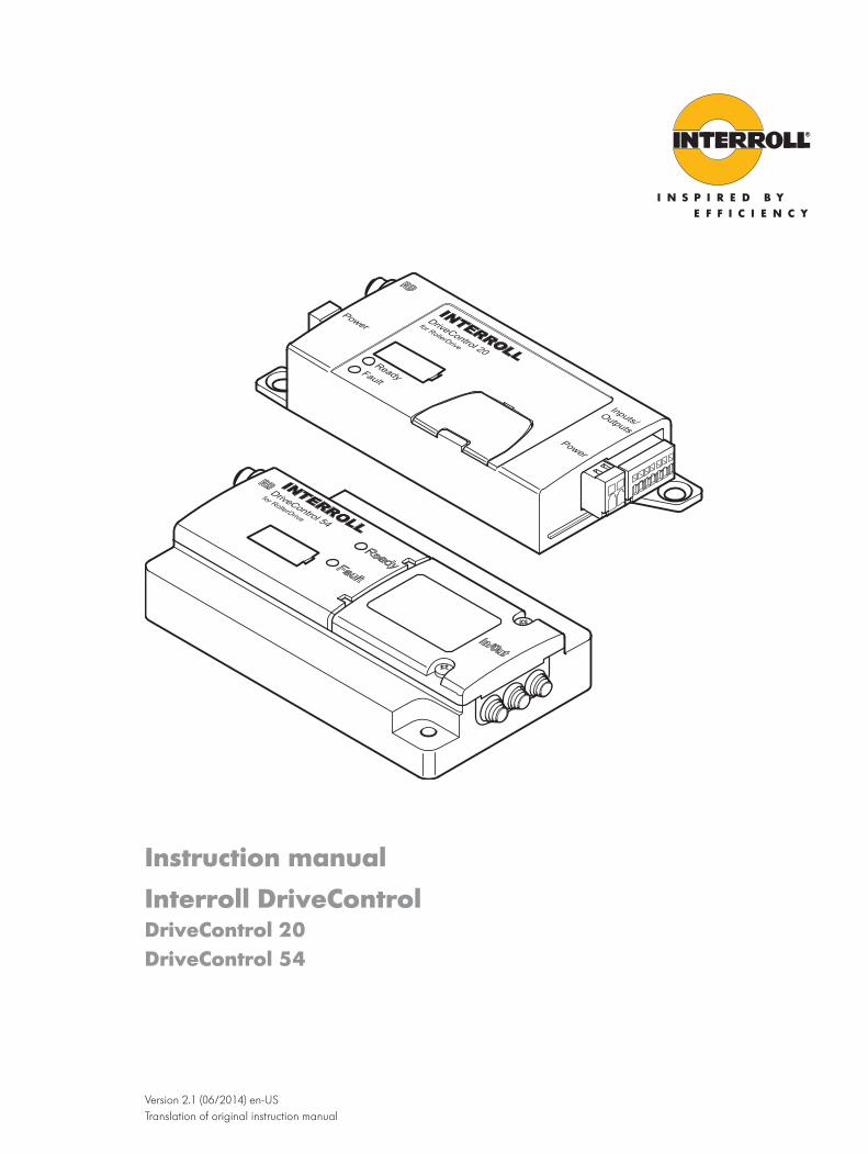
Instruction manualInterroll DriveControlDriveControl 20 DriveControl 54
Version 2.1 (06/2014) en-US Translation of original instruction manual
Manufacturer's address
Interroll Engineering GmbH Hoeferhof 16 D-42929 Wermelskirchen Ph. +49 2193 23 0 Fax. +49 2190 2022 www.interroll.com
Copyright
The copyright of this manual remains with Interroll Engineering GmbH. The operating instructions contain technical regulations and drawings which may not be reproduced partially or in full, transmitted by any means, utilized without permission for competitive purposes or disclosed to third parties.
1004060 Version 2.1 (06/2014) en-US Translation of original instruction manual
Interroll DriveControl 20 / DriveControl 54
Version 2.1 (06/2014) en-US Translation of original instruction manual
3
Table of Contents
Introduction 5Information about the manual 5
Contents 5The manual is part of the product 5
Warning notices in this manual 5Symbols 5
Safety 6State of the art 6Intended use 6Personnel qualification 6
Operators 6Service personnel 6Electricians 6
Dangers 7Bodily injury 7Electricity 7Working environment 7Faults during operation 7Maintenance 7Accidental motor start 7
Interfaces to other devices 7Operating modes 8
Normal mode 8Special mode 8
Product information 9Product description 9
Functions 9Energy feedback 9Temperature protection 9Lock period for signal modifications 9Setting the speed 9Ramp function 10
Components 10Scope of supply 11
DriveControl 20 11DriveControl 54 11
Technical data 12Meaning of the LEDs 12DIP switches 13Dimensions 14
Transport and storage 15Ambient conditions for transport and storage 15Transport 15Storage 15

Interroll DriveControl 20 / DriveControl 54Table of Contents
4 Version 2.1 (06/2014) en-US Translation of original instruction manual
Assembly 16Warning information for assembly 16Warning notices concerning the electrical installation 16Installation of the DriveControl 20/54 in a conveyor system 17Electrical installation 17
DriveControl 20 17DriveControl 54 18
Inputs and outputs 19DriveControl 20 19DriveControl 54 21
Wiring diagrams 22Basic circuit 22Minimum circuit 23Error signal connection 24
Initial startup and operation 25Initial startup 25
Checks before initial startup 25Pre-commissioning checks 25
Operation 25Change setting the speed of the DriveControl (internal) 26Speed setting via digital inputs (external) 27
Maintenance and cleaning 28Warning notices concerning maintenance and cleaning 28Maintenance 28
Checking DriveControl 28Replacing the DriveControl 28
Cleaning 28
Troubleshooting 29Troubleshooting 29
Decommissioning and disposal 30Shutdown 30Disposal 30
Appendix 31Electrical data of connectors 31
Connector of inputs/outputs 31RollerDrive connector 32
Declaration of Conformity 34

Interroll DriveControl 20 / DriveControl 54
Version 2.1 (06/2014) en-US Translation of original instruction manual
5
Introduction
Information about the manual
This manual contains important notes and information about the various operating phases of the DriveControl 20/54.
The manual describes the DriveControl 20/54 as it is delivered by Interroll.
In addition to this manual, special contractual agreements and technical documents apply to special versions.
4 For trouble-free, safe operation and warranty claims, read the manual first and follow the instructions.
4 Keep the manual near to the DriveControl 20/54.4 Pass the manual on to any subsequent operator or occupant.4 NOTICE! The manufacturer does not accept any liability for faults or defects due to
non-observance of this manual.4 If you have any questions after reading the operating instructions, please contact the Interroll
customer service. Contact persons close to you can be found on the Internet under interroll.com/contacts.
Warning notices in this manualThe warning notices refer to risks which may arise while usage the DriveControl 20/54. They are available in four danger levels identified by the signal word:
Signal word Meaning
DANGER Identifies a danger with high risk that can lead to death or serious injury if it is not avoided.
WARNING Identifies a danger with medium risk that can lead to death or serious injury if it is not avoided.
CAUTION Identifies a danger with low risk that can lead to minor or medium injury if it is not avoided.
NOTICE Identifies a danger that can lead to property damages.
Symbols
This symbol marks useful and important information.
Requirement: R This symbol represents a prerequisite to be met prior to assembly and maintenance work.
4 This symbol marks the steps to be carried out.
Contents
The manual is part of the product

Interroll DriveControl 20 / DriveControl 54
6 Version 2.1 (06/2014) en-US Translation of original instruction manual
Safety
State of the artThe DriveControl 20/54 has been built to comply with the state of the art and is operationally safe in its delivered state. Nevertheless, users may encounter hazards during use:
Disregarding the notices in this manual may lead to serious injury.
4 Carefully read the manual and follow its content.
Intended useThe DriveControl 20/54 may only be used for industrial applications and in an industrial environment to control a RollerDrive EC310. It must be integrated into a conveyor module or conveyor system. Any other use is considered inappropriate.
Any modifications that affect the safety of the product are not permitted.
The DriveControl 20/54 may only be operated within the defined operating limits.
Deviating applications require the approval of Interroll.
Personnel qualificationUnqualified personnel cannot recognize risks and, as a result, is subject to greater dangers.
4 Authorize only qualified personnel with the activities described in these operating instructions.4 The operating company must ensure that the personnel follows locally applicable regulations
and rules during their work with regard to safety and dangers.
The following target groups are addressed in these operating instructions:
Operators have been instructed in the operation and cleaning of the DriveControl 20/54 and follow the safety guidelines.
The service personnel features a technical training and performs the maintenance and repair tasks.
Persons working on electrical equipment must have undergone technical training or training provided by the manufacturer.
Operators
Service personnel
Electricians
Interroll DriveControl 20 / DriveControl 54Safety
Version 2.1 (06/2014) en-US Translation of original instruction manual
7
Dangers
The following list provides information about the various types of danger or damage that may occur while working with the DriveControl 20/54.
4 Maintenance or repair work must only be performed by authorized and qualified persons in accordance with the applicable regulations.
4 Before using the DriveControl 20/54, ensure that no unauthorized persons are near the conveyor.
4 Only operate the DriveControl 20/54 with control voltages complying with the requirements of EN 60401-1, PELV.
4 Only perform installation and maintenance work after you have switched off the power.4 Ensure that the power cannot be turned on accidentally.
4 Do not use the DriveControl 20/54 in areas where there is a hazard of explosion.4 Remove material that is not required and unnecessary objects from the workspace.
4 Regularly inspect the DriveControl 20/54 for visible damage.4 If you notice smoke, switch off the power immediately and ensure that it cannot be switched
on again accidentally.4 Contact qualified personnel immediately to find the source of the fault.
4 Because the product does not require maintenance, you only need to inspect the DriveControl regularly for visible damage and that all cables and screws are firmly in place.
4 Ensure that a connected motor cannot start accidentally, particularly for assembly, maintenance work and troubleshooting.
Interfaces to other devicesBy assembling the DriveControl in a conveyor module, potential hazards may occur. These are not part of this manual and have to be analyzed during the design, installation and startup of the complete system.
4 After assembling the DriveControl in a conveyor module, check the whole system for a new potential dangerous spot before switching on the conveyor.
4 Additional constructive measures may be required.
Bodily injury
Electricity
Working environment
Faults during operation
Maintenance
Accidental motor start
Interroll DriveControl 20 / DriveControl 54Safety
8 Version 2.1 (06/2014) en-US Translation of original instruction manual
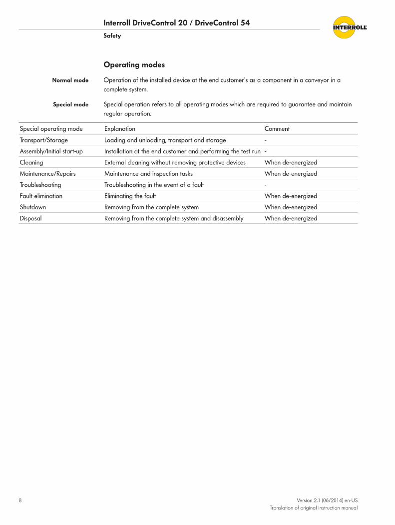
Operating modes
Operation of the installed device at the end customer's as a component in a conveyor in a complete system.
Special operation refers to all operating modes which are required to guarantee and maintain regular operation.
Special operating mode Explanation Comment
Transport/Storage Loading and unloading, transport and storage -
Assembly/Initial start-up Installation at the end customer and performing the test run -
Cleaning External cleaning without removing protective devices When de-energized
Maintenance/Repairs Maintenance and inspection tasks When de-energized
Troubleshooting Troubleshooting in the event of a fault -
Fault elimination Eliminating the fault When de-energized
Shutdown Removing from the complete system When de-energized
Disposal Removing from the complete system and disassembly When de-energized
Normal mode
Special mode

Interroll DriveControl 20 / DriveControl 54
Version 2.1 (06/2014) en-US Translation of original instruction manual
9
Product information
Product descriptionThe DriveControl 20/54 is intended to control the speed and rotation direction of the RollerDrive EC310.
• Regenerative braking: When the RollerDrive motor brakes, it acts as a generator and feeds energy back into the power supply. The DriveControl has a built in brake chopper (load resistor) to limit the DC voltage on the connection to a stable level.
• Diagnostics: LEDs indicate the operating condition of the DriveControl and the RollerDrive as well as the operating voltage (See "Meaning of the LEDs", page 12). An error signal can also be output.
When the speed of a rotating RollerDrive is abruptly reduced (e. g. by taking away or reducing the start signal at the DriveControl), the RollerDrive briefly rotates further (depending on the weight of the conveyed goods being stopped) and thus functions as a generator. The voltage generated in this way increases the supply voltage of the RollerDrive. This increased voltage is partly fed to the DC supply (to max. 30 V) and partly converted to heat via a brake chopper resistance on the DriveControl. The regenerated power is then available for other consumers. The more precisely 24 V are complied to in the voltage supply the greater the voltage range in which the DC network can be fed back to.
The brake chopper resistor is temperature-controlled. If because of specific application properties (e. g. high conveying weight or high conveying speed) the brake chopper resistance is frequently switched, the DriveControl switches off when it becomes too hot (approx. 90 °C / 194 °F inner temperature). If temperature protection is activated, this state is indicated by the LEDs and no start signal will be transmitted to the RollerDrive. When the DriveControl has cooled down, the RollerDrive restarts automatically when a signal is pending. The DriveControl cools down quicker if it is mounted on a flat surface, ideally metal.
NOTICEDriveControl failure from overheating
4 Do not perform a voltage reset when temperature protection is active.
The following signals are protected by the firmware to ensure functionality with flank-instable or bouncing levels. This means that after a signal status change, there is a time gap of 20 ms in which no additional status change is accepted. • DIP switch SPEED A, SPEED B, SPEED C, SPEED D, DIR, RAMP • Common RollerDrive faults, SPEED A, SPEED B, SPEED C, DIR
The speed of the RollerDrive can be adjusted in two different ways by the DriveControl: • internally via four DIP switches with 15 levels (is handled with priority and enables finer
setting levels)
Functions
Energy feedback
Temperature protection
Lock period for signal modifications
Setting the speed
Interroll DriveControl 20 / DriveControl 54Product information
10 Version 2.1 (06/2014) en-US Translation of original instruction manual
• externally via three digital inputs with eight levels (speed modifications are also possible in running operation, whereby a form of ramp function can be implemented with corresponding switching of a PLC)
The speed setting is converted to an analog control voltage by the DriveControl and output by the RollerDrive as a reference setting. This reference setting is independent of the RollerDrive gears and their diameter.
Speed setting of the See "Operation", page 25.
The acceleration and braking behavior of the RollerDrive is defined by its own moment of inertia, the gears used, the conveying speed, the moment of inertia of the connected conveyor rollers, the selected torque transmission and the goods transported.
An acceleration/deceleration ramp can be switched on with the RAMP DIP switch.
The ramps are of equal size, measure 0.39 seconds each, and cannot be changed with respect to time.
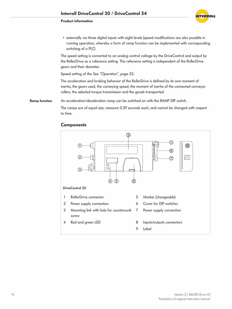
Components
DriveControl 20
1 RollerDrive connector 5 Marker (changeable)
2 Power supply connection 6 Cover for DIP switches
3 Mounting link with hole for countersunk screw
7 Power supply connection
4 Red and green LED 8 Inputs/outputs connectors
9 Label
Ramp function
Interroll DriveControl 20 / DriveControl 54Product information
Version 2.1 (06/2014) en-US Translation of original instruction manual
11
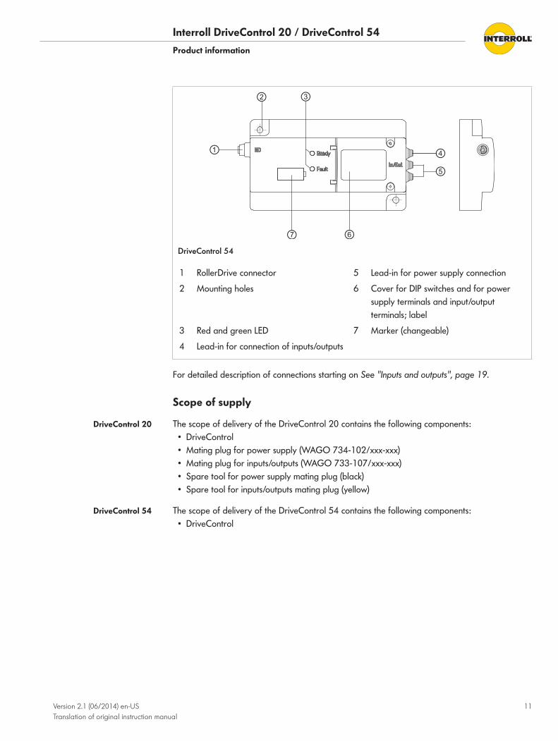
DriveControl 54
1 RollerDrive connector 5 Lead-in for power supply connection
2 Mounting holes 6 Cover for DIP switches and for power supply terminals and input/output terminals; label
3 Red and green LED 7 Marker (changeable)
4 Lead-in for connection of inputs/outputs
For detailed description of connections starting on See "Inputs and outputs", page 19.
Scope of supply
The scope of delivery of the DriveControl 20 contains the following components: • DriveControl • Mating plug for power supply (WAGO 734-102/xxx-xxx) • Mating plug for inputs/outputs (WAGO 733-107/xxx-xxx) • Spare tool for power supply mating plug (black) • Spare tool for inputs/outputs mating plug (yellow)
The scope of delivery of the DriveControl 54 contains the following components: • DriveControl
DriveControl 20
DriveControl 54
Interroll DriveControl 20 / DriveControl 54Product information
12 Version 2.1 (06/2014) en-US Translation of original instruction manual
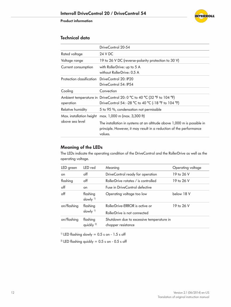
Technical data
DriveControl 20-54
Rated voltage 24 V DC
Voltage range 19 to 26 V DC (reverse-polarity protection to 30 V)
Current consumption with RollerDrive: up to 5 A without RollerDrive: 0.5 A
Protection classification DriveControl 20: IP20 DriveControl 54: IP54
Cooling Convection
Ambient temperature in operation
DriveControl 20: 0 °C to 40 °C (32 °F to 104 °F) DriveControl 54: -28 °C to 40 °C (-18 °F to 104 °F)
Relative humidity 5 to 95 %, condensation not permissible
Max. installation height above sea level
max. 1,000 m (max. 3,300 ft)
The installation in systems at an altitude above 1,000 m is possible in principle. However, it may result in a reduction of the performance values.
Meaning of the LEDsThe LEDs indicate the operating condition of the DriveControl and the RollerDrive as well as the operating voltage.
LED green LED red Meaning Operating voltage
on off DriveControl ready for operation 19 to 26 V
flashing off RollerDrive rotates / is controlled 19 to 26 V
off on Fuse in DriveControl defective
off flashing slowly 1)
Operating voltage too low below 18 V
on/flashing flashing slowly 1)
RollerDrive-ERROR is active or
RollerDrive is not connected
19 to 26 V
on/flashing flashing quickly 2)
Shutdown due to excessive temperature in chopper resistance
1) LED flashing slowly = 0.5 s on - 1.5 s off2) LED flashing quickly = 0.5 s on - 0.5 s off
Interroll DriveControl 20 / DriveControl 54Product information
Version 2.1 (06/2014) en-US Translation of original instruction manual
13
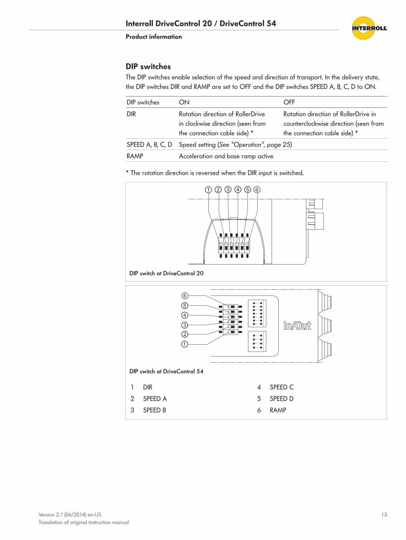
DIP switchesThe DIP switches enable selection of the speed and direction of transport. In the delivery state, the DIP switches DIR and RAMP are set to OFF and the DIP switches SPEED A, B, C, D to ON.
DIP switches ON OFF
DIR Rotation direction of RollerDrive in clockwise direction (seen from the connection cable side) *
Rotation direction of RollerDrive in counterclockwise direction (seen from the connection cable side) *
SPEED A, B, C, D Speed setting (See "Operation", page 25)
RAMP Acceleration and base ramp active
* The rotation direction is reversed when the DIR input is switched.
DIP switch at DriveControl 20
DIP switch at DriveControl 54
1 DIR 4 SPEED C
2 SPEED A 5 SPEED D
3 SPEED B 6 RAMP
Interroll DriveControl 20 / DriveControl 54Product information
14 Version 2.1 (06/2014) en-US Translation of original instruction manual
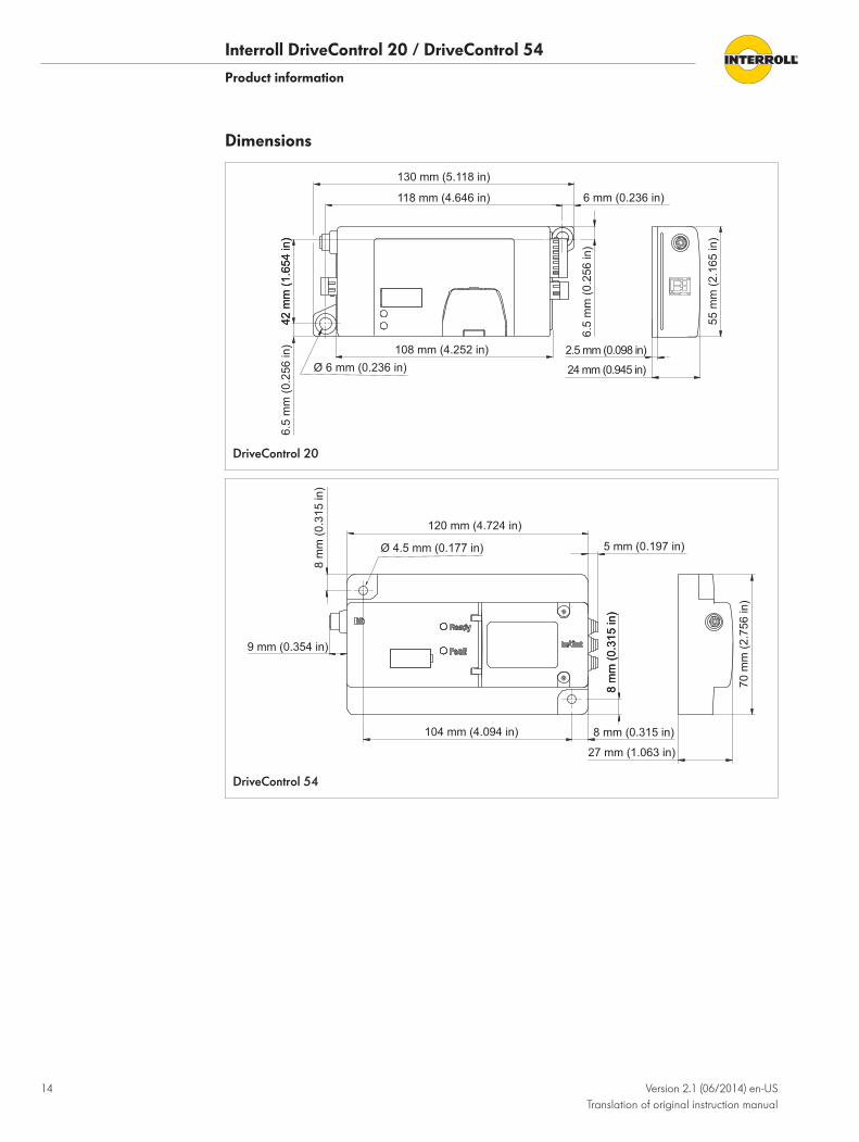
Dimensions
6.5
mm
(0.2
56 in
) 2.5 mm (0.098 in)
55 m
m (2
.165
in)
6.5
mm
(0.2
56 in
)
6 mm (0.236 in)118 mm (4.646 in)
130 mm (5.118 in)
24 mm (0.945 in)
108 mm (4.252 in)
42 m
m (1
.654
in)
42 m
m (1
.654
in)
Ø 6 mm (0.236 in)
DriveControl 20
8 m
m (0
.315
in)
8 m
m (0
.315
in)
8 m
m (0
.315
in)
70 m
m (2
.756
in)
8 mm (0.315 in)104 mm (4.094 in)
27 mm (1.063 in)
120 mm (4.724 in)
9 mm (0.354 in)
5 mm (0.197 in)Ø 4.5 mm (0.177 in)
DriveControl 54

Interroll DriveControl 20 / DriveControl 54
Version 2.1 (06/2014) en-US Translation of original instruction manual
15
Transport and storage
Ambient conditions for transport and storage
Permissible ambient temperature -40 °C to 85 °C (-40 °F to 185 °F)
Permissible relative humidity 5 to 95 %
Condensation not permissible.
Transport • Every DriveControl is packaged in its own cardboard box.
CAUTIONImproper transport poses an injury hazard.
4 Transport-related tasks should only be carried out by qualified and authorized persons.4 Follow the instructions below.
4 Do not stack more than four cardboard boxes on top of each other.4 Check that the DriveControl is correctly fixed in place prior to transport.4 Avoid serious impacts during transport.4 Check every DriveControl for visible damage and completeness (mating plugs and spare
tools) following transport (See "Scope of supply", page 11).4 In the event of damage, take photos of the damaged parts.4 Report any damage caused by transport immediately to the transport company and Interroll
to retain the right to claim for compensation.4 Do not expose the DriveControls to large temperature fluctuations as this could result in
condensation.
Storage
NOTICERisk of damage to property due to improper storage
4 Do not stack more than four cardboard boxes on top of each other.
4 Inspect each DriveControl for damage after storage.
Interroll DriveControl 20 / DriveControl 54
16 Version 2.1 (06/2014) en-US Translation of original instruction manual
Assembly
Warning information for assembly
Risk of damage can lead to failure or shortened life expectancy of the DriveControl.
4 Do not drop or mishandle the DriveControl to avoid internal damage.4 Check each DriveControl visually for damage before assembly.
Warning notices concerning the electrical installation
Improper electrical installation can leads to damage of the DriveControl.
4 Electrical work should only be performed by qualified and authorized persons.4 Disconnect the power supply before installing, removing or rewiring the DriveControl.4 Ensure that no hazardous voltage can come into contact with the connections or the housing,
not even in the event of a malfunction or fault.4 Do not connect AC current to the RollerDrive or the DriveControl at any time, as this will
cause irreparable damage to the device.4 Do not use earth connections or earth wires as a protective conductor (PE).4 Do not apply too much tension or load to the motor plug. The cable insulation can become
damaged if the cable is bent at the plug and the DriveControl or the RollerDrive could fail.4 Ensure that existing electrical installations do not interfere with the DriveControl or the
RollerDrive.4 Only use cables that are dimensioned sufficiently for the application.4 Ensure that current load at each terminal or terminal block does not exceed 10 A.4 Ensure that the switching power supply unit supplying the DriveControl supplies a nominal
DC voltage of 24 V with a maximum deviation of ±8 %.4 Ensure that the RollerDrive, the DriveControl and the voltage source are connected to the
conveyor frame or supporting structure in such a way that they are properly earthed. Incorrect earthing can result in the build-up of static charge, causing the motor or DriveControl to malfunction or fail prematurely.
4 Only use the specified mating plug (See "Inputs and outputs", page 19) and the spare tool supplied.
4 Only apply operating voltage when all of the cables have been connected.
Interroll DriveControl 20 / DriveControl 54Assembly
Version 2.1 (06/2014) en-US Translation of original instruction manual
17
Installation of the DriveControl 20/54 in a conveyor system4 Locate a flat surface for mounting the DriveControl.4 Use the DriveControl as a template and mark the center of both mounting holes.
For the distance between the holes, See "Dimensions", page 14.4 Drill two ø 5.6 - 6 mm (0.22 - 0.24 in) mounting holes at the marked spots.4 Bolt on the DriveControl.4 Ensure that the housing is not distorted.
Electrical installation
The DriveControl 20/54 is equipped with an internal, non-replaceable fuse intended exclusively for device protection. Protection of the supply cables must be ensured by the operator.
Required conductors:
Connection Conductor cross-section
Inputs/Outputs Fine-strand: 0.08 to 0.5 mm2 (AWG 28 to 21)
Fine-strand with end-splice: 0.25 to 0.34 mm2 (AWG 24 to 22)
Stripped length: 5 to 6 mm (0.2 to 0.24 in)
Power supply Fine-strand, H05(07) V-K: 1.5 mm2 (AWG 16)
(optionally with end-splice according to DIN 46228/1)
Stripped length: 6 to 7 mm (0.24 to 0.27 in)
4 Prepare wire ends according to the recommendations of the contact manufacturer.4 Insert the input/output wires into the mating plug with the yellow spare tool (See "Inputs and
outputs", page 19).4 Insert the power supply wires into the mating plug with the black spare tool.4 Insert the mating plug into the DriveControl.4 If necessary, set the DIP switches according to requirements (See "Operation", page 25).4 Insert the plug of the RollerDrive so that the "RD" labeling can be read for the DriveControl
and the "EC310" labeling is to the rear, i.e. cannot be read.
DriveControl 20
Interroll DriveControl 20 / DriveControl 54Assembly
18 Version 2.1 (06/2014) en-US Translation of original instruction manual
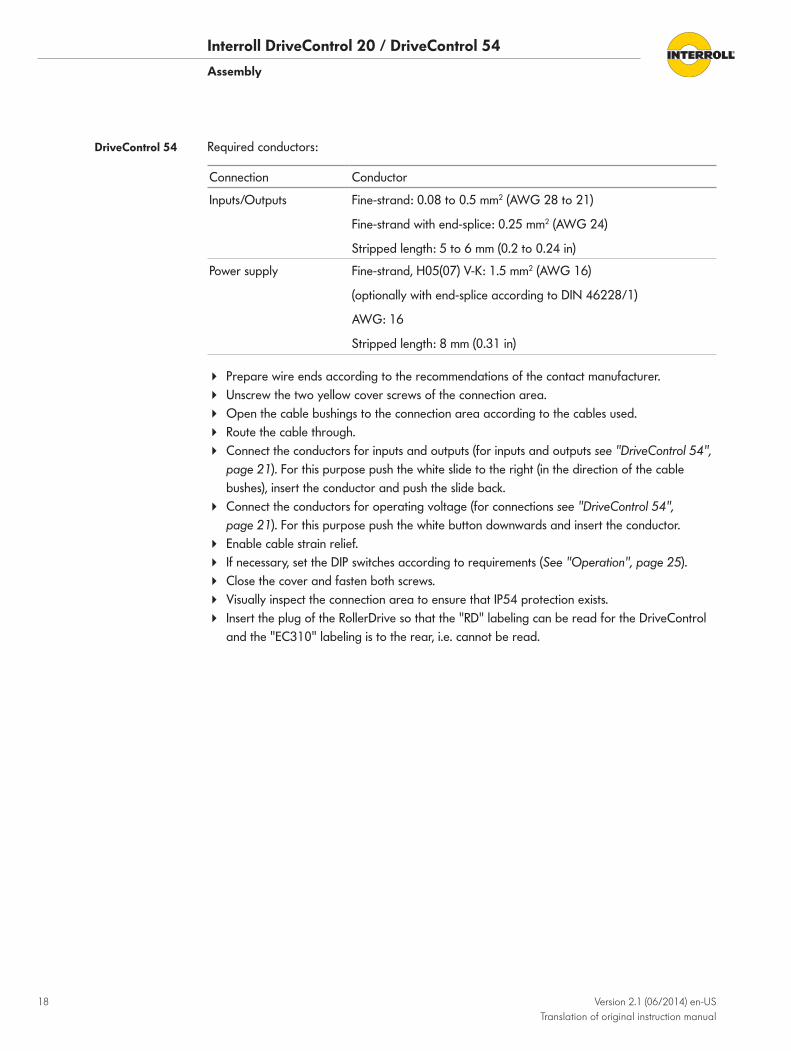
Required conductors:
Connection Conductor
Inputs/Outputs Fine-strand: 0.08 to 0.5 mm2 (AWG 28 to 21)
Fine-strand with end-splice: 0.25 mm2 (AWG 24)
Stripped length: 5 to 6 mm (0.2 to 0.24 in)
Power supply Fine-strand, H05(07) V-K: 1.5 mm2 (AWG 16)
(optionally with end-splice according to DIN 46228/1)
AWG: 16
Stripped length: 8 mm (0.31 in)
4 Prepare wire ends according to the recommendations of the contact manufacturer.4 Unscrew the two yellow cover screws of the connection area.4 Open the cable bushings to the connection area according to the cables used.4 Route the cable through.4 Connect the conductors for inputs and outputs (for inputs and outputs see "DriveControl 54",
page 21). For this purpose push the white slide to the right (in the direction of the cable bushes), insert the conductor and push the slide back.
4 Connect the conductors for operating voltage (for connections see "DriveControl 54", page 21). For this purpose push the white button downwards and insert the conductor.
4 Enable cable strain relief.4 If necessary, set the DIP switches according to requirements (See "Operation", page 25).4 Close the cover and fasten both screws.4 Visually inspect the connection area to ensure that IP54 protection exists.4 Insert the plug of the RollerDrive so that the "RD" labeling can be read for the DriveControl
and the "EC310" labeling is to the rear, i.e. cannot be read.
DriveControl 54

Interroll DriveControl 20 / DriveControl 54Assembly
Version 2.1 (06/2014) en-US Translation of original instruction manual
19
Inputs and outputs
RollerDrive connector: 8 mm snap-in, 5-pin, pin location in accordance with DIN EN 61076-2
1 +24 V DC 4 Fault input
2 Output for direction of rotation 5 Speed output
3 Ground
Power supply connector, mating plug WAGO 734-102/xxx-xxx
1 +24 V DC 2 GND (ground)
The power supply connection is double in order to connect the power supply from the most convenient side during installation. Both connections are directly interconnected internally. The power supply can be implemented with a DriveControl so that a maximum of two DriveControls can be connected in sequence.
DriveControl 20

Interroll DriveControl 20 / DriveControl 54Assembly
20 Version 2.1 (06/2014) en-US Translation of original instruction manual
Inputs/outputs connectors
Mating plug: WAGO 733-107/xxx-xxx
1 COMMON GND (common signal ground)
5 SPEED C (input for speed setting)
2 24 V EXT (voltage supply for ERROR signal)
6 SPEED B (input for speed setting)
3 ERROR (output for fault) 7 SPEED A (input for speed setting)
4 DIR (direction of rotation)
Interroll DriveControl 20 / DriveControl 54Assembly
Version 2.1 (06/2014) en-US Translation of original instruction manual
21
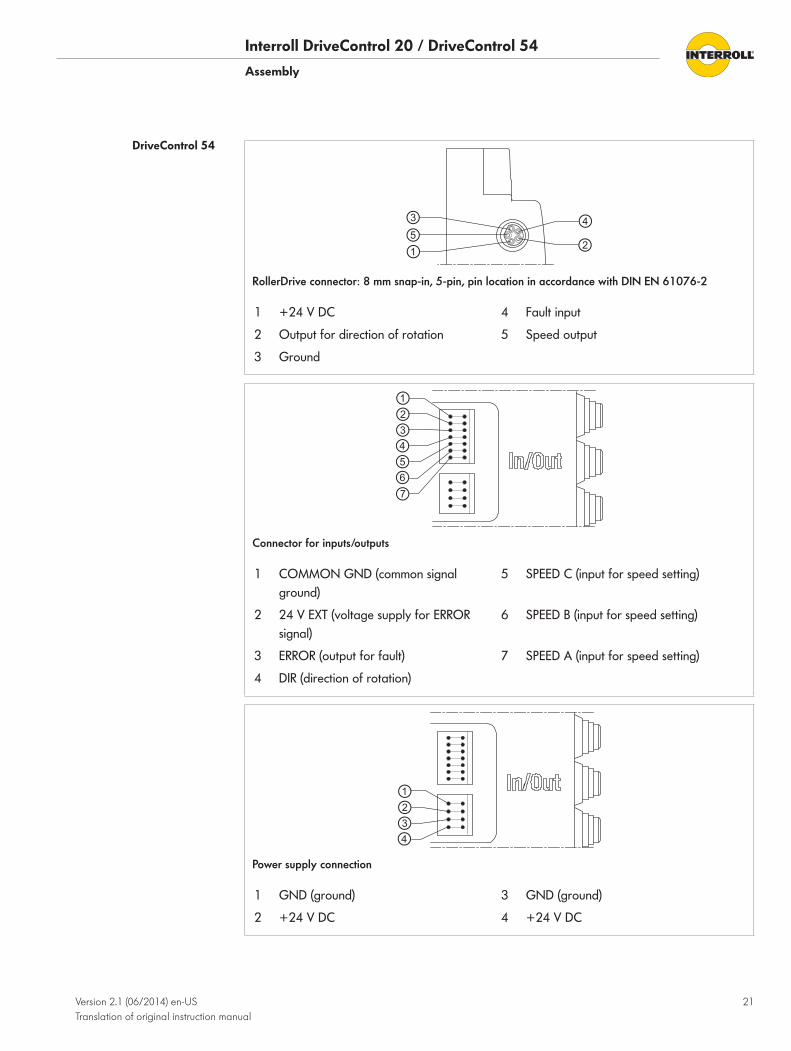
RollerDrive connector: 8 mm snap-in, 5-pin, pin location in accordance with DIN EN 61076-2
1 +24 V DC 4 Fault input
2 Output for direction of rotation 5 Speed output
3 Ground
Connector for inputs/outputs
1 COMMON GND (common signal ground)
5 SPEED C (input for speed setting)
2 24 V EXT (voltage supply for ERROR signal)
6 SPEED B (input for speed setting)
3 ERROR (output for fault) 7 SPEED A (input for speed setting)
4 DIR (direction of rotation)
Power supply connection
1 GND (ground) 3 GND (ground)
2 +24 V DC 4 +24 V DC
DriveControl 54
Interroll DriveControl 20 / DriveControl 54Assembly
22 Version 2.1 (06/2014) en-US Translation of original instruction manual
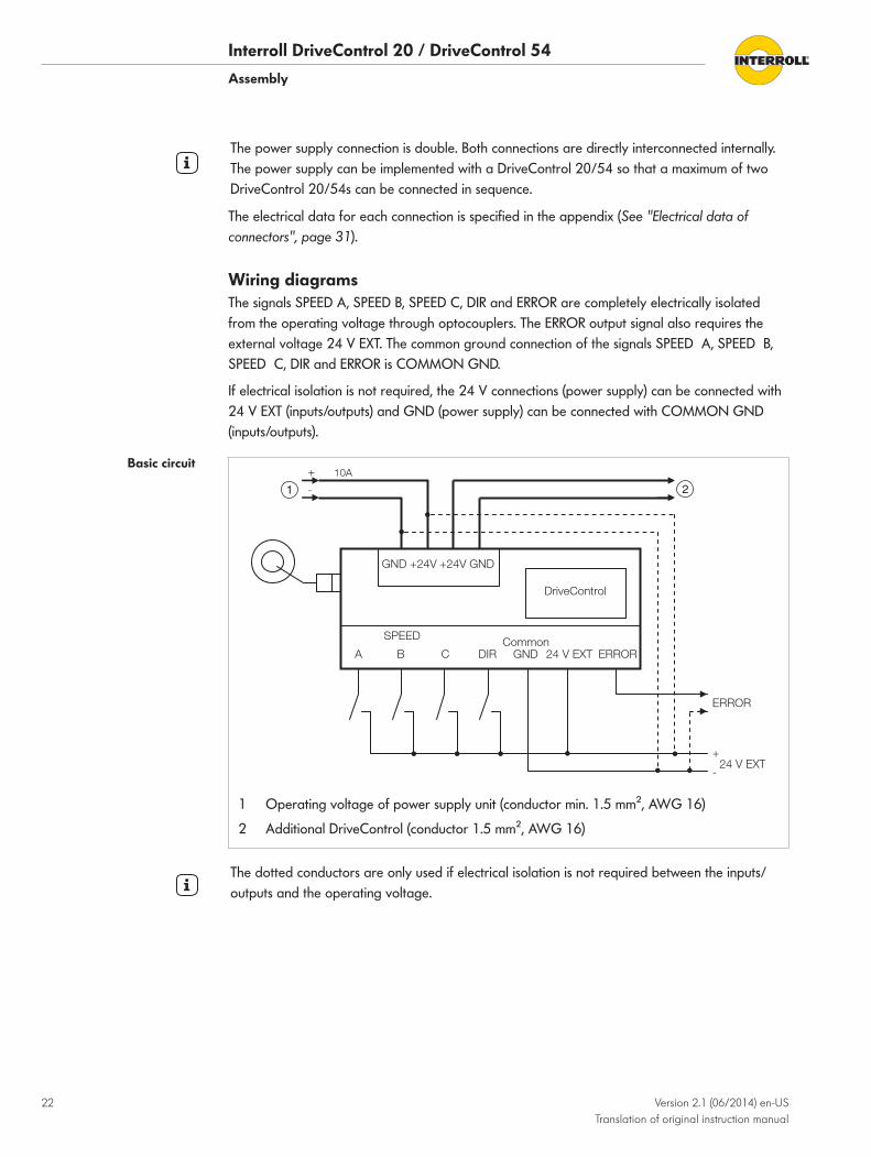
The power supply connection is double. Both connections are directly interconnected internally. The power supply can be implemented with a DriveControl 20/54 so that a maximum of two DriveControl 20/54s can be connected in sequence.
The electrical data for each connection is specified in the appendix (See "Electrical data of connectors", page 31).
Wiring diagramsThe signals SPEED A, SPEED B, SPEED C, DIR and ERROR are completely electrically isolated from the operating voltage through optocouplers. The ERROR output signal also requires the external voltage 24 V EXT. The common ground connection of the signals SPEED A, SPEED B, SPEED C, DIR and ERROR is COMMON GND.
If electrical isolation is not required, the 24 V connections (power supply) can be connected with 24 V EXT (inputs/outputs) and GND (power supply) can be connected with COMMON GND (inputs/outputs).
SPEED
ACommon
GND 24 V EXT ERROR
10A
DriveControl
ERROR
+
-
+
-24 V EXT
GND +24V +24V GND
DIR CB
1 Operating voltage of power supply unit (conductor min. 1.5 mm², AWG 16)
2 Additional DriveControl (conductor 1.5 mm², AWG 16)
The dotted conductors are only used if electrical isolation is not required between the inputs/outputs and the operating voltage.
Basic circuit
Interroll DriveControl 20 / DriveControl 54Assembly
Version 2.1 (06/2014) en-US Translation of original instruction manual
23
SPEED
A B C DIR Common
GND 24 V EXT ERROR
+
-
GND +24V +24V GND
DriveControl
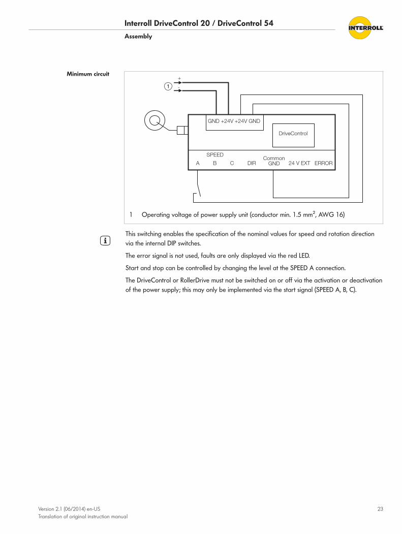
1 Operating voltage of power supply unit (conductor min. 1.5 mm², AWG 16)
This switching enables the specification of the nominal values for speed and rotation direction via the internal DIP switches.
The error signal is not used, faults are only displayed via the red LED.
Start and stop can be controlled by changing the level at the SPEED A connection.
The DriveControl or RollerDrive must not be switched on or off via the activation or deactivation of the power supply; this may only be implemented via the start signal (SPEED A, B, C).
Minimum circuit

Interroll DriveControl 20 / DriveControl 54Assembly
24 Version 2.1 (06/2014) en-US Translation of original instruction manual
To evaluate the error signal, the input 24 V EXT must be supplied with a voltage of 24 V DC.
4 Connect input 24 V EXT with the operating voltage.
The error signal of a maximum of six DriveControls can be linked via series switching. The logic level "no error" is hereby reduced by 1.1 V per DriveControl.
4 Connect ERROR output of the upstream DriveControl with the input 24 V EXT of the downstream DriveControl.
PLC
IN X.X
GND 24 V
Com
mon G
ND
ER
RO
R
24 V E
XT
DriveControl DriveControl DriveControlC
omm
on GN
D
ER
RO
R
24 V E
XT
Com
mon G
ND
ER
RO
R
24 V E
XT
When operating voltage is disconnected, the ERROR output switches to the error condition. This ensures correct display of faults when the error signal of several DriveControls has been linked and the operating voltage of a DriveControl is switched off or if a cable defect (e.g. loosened contact, cable rupture) occurs.
When operating voltage is switched on, the error signal is active until the internal microcontroller assumes control. If no error exists, the error signal is canceled approx. 400 ms after activating the operating voltage.
Error signal connection
Interroll DriveControl 20 / DriveControl 54
Version 2.1 (06/2014) en-US Translation of original instruction manual
25
Initial startup and operation
Initial startup
4 Ensure that the DriveControl 20/54 has been correctly fastened to the profile and that all screws have been correctly tightened.
4 Ensure that there are no additional areas of danger caused by interfaces to other components.
4 Ensure that the wiring is in accordance with the specification and legal directives.4 Check all protection devices.4 Ensure that no bystanders are in dangerous areas around the conveyor.
4 Check the DriveControl for visible damage.4 Check the DIP switch settings.4 Check all protection devices.4 Clearly specify and monitor the way goods are placed on the conveyor.4 Ensure that the RollerDrive is not blocked.4 Ensure that there are no bystanders in danger areas around the conveyor.
Operation
CAUTIONAccidental start-up of the RollerDrive
Danger of crushing of limbs and damage to goods
4 Ensure that no unauthorized persons are near the conveyor before switching on the operating voltage.
Ambient conditions during operation See "Technical data", page 12.
Checks before initial startup
Pre-commissioning checks
Interroll DriveControl 20 / DriveControl 54Initial startup and operation
26 Version 2.1 (06/2014) en-US Translation of original instruction manual
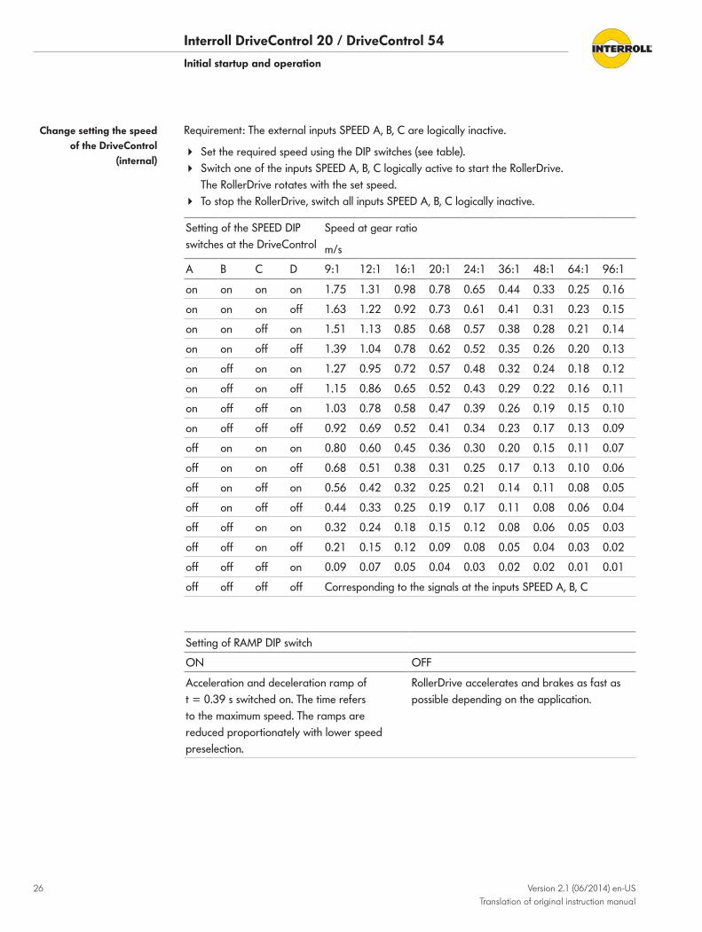
Requirement: The external inputs SPEED A, B, C are logically inactive.
4 Set the required speed using the DIP switches (see table).4 Switch one of the inputs SPEED A, B, C logically active to start the RollerDrive.
The RollerDrive rotates with the set speed.4 To stop the RollerDrive, switch all inputs SPEED A, B, C logically inactive.
Setting of the SPEED DIP switches at the DriveControl
Speed at gear ratio
m/s
A B C D 9:1 12:1 16:1 20:1 24:1 36:1 48:1 64:1 96:1
on on on on 1.75 1.31 0.98 0.78 0.65 0.44 0.33 0.25 0.16
on on on off 1.63 1.22 0.92 0.73 0.61 0.41 0.31 0.23 0.15
on on off on 1.51 1.13 0.85 0.68 0.57 0.38 0.28 0.21 0.14
on on off off 1.39 1.04 0.78 0.62 0.52 0.35 0.26 0.20 0.13
on off on on 1.27 0.95 0.72 0.57 0.48 0.32 0.24 0.18 0.12
on off on off 1.15 0.86 0.65 0.52 0.43 0.29 0.22 0.16 0.11
on off off on 1.03 0.78 0.58 0.47 0.39 0.26 0.19 0.15 0.10
on off off off 0.92 0.69 0.52 0.41 0.34 0.23 0.17 0.13 0.09
off on on on 0.80 0.60 0.45 0.36 0.30 0.20 0.15 0.11 0.07
off on on off 0.68 0.51 0.38 0.31 0.25 0.17 0.13 0.10 0.06
off on off on 0.56 0.42 0.32 0.25 0.21 0.14 0.11 0.08 0.05
off on off off 0.44 0.33 0.25 0.19 0.17 0.11 0.08 0.06 0.04
off off on on 0.32 0.24 0.18 0.15 0.12 0.08 0.06 0.05 0.03
off off on off 0.21 0.15 0.12 0.09 0.08 0.05 0.04 0.03 0.02
off off off on 0.09 0.07 0.05 0.04 0.03 0.02 0.02 0.01 0.01
off off off off Corresponding to the signals at the inputs SPEED A, B, C
Setting of RAMP DIP switch
ON OFF
Acceleration and deceleration ramp of t = 0.39 s switched on. The time refers to the maximum speed. The ramps are reduced proportionately with lower speed preselection.
RollerDrive accelerates and brakes as fast as possible depending on the application.
Change setting the speed of the DriveControl
(internal)
Interroll DriveControl 20 / DriveControl 54Initial startup and operation
Version 2.1 (06/2014) en-US Translation of original instruction manual
27
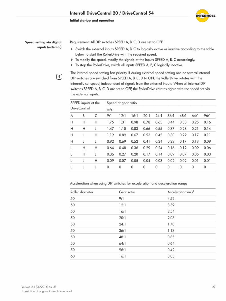
Requirement: All DIP switches SPEED A, B, C, D are set to OFF.
4 Switch the external inputs SPEED A, B, C to logically active or inactive according to the table below to start the RollerDrive with the required speed.
4 To modify the speed, modify the signals at the inputs SPEED A, B, C accordingly.4 To stop the RollerDrive, switch all inputs SPEED A, B, C logically inactive.
The internal speed setting has priority. If during external speed setting one or several internal DIP switches are switched from SPEED A, B, C, D to ON, the RollerDrive rotates with this internally set speed, independent of signals from the external inputs. When all internal DIP switches SPEED A, B, C, D are set to OFF, the RollerDrive rotates again with the speed set via the external inputs.
SPEED inputs at the DriveControl
Speed at gear ratio
m/s
A B C 9:1 12:1 16:1 20:1 24:1 36:1 48:1 64:1 96:1
H H H 1.75 1.31 0.98 0.78 0.65 0.44 0.33 0.25 0.16
H H L 1.47 1.10 0.83 0.66 0.55 0.37 0.28 0.21 0.14
H L H 1.19 0.89 0.67 0.53 0.45 0.30 0.22 0.17 0.11
H L L 0.92 0.69 0.52 0.41 0.34 0.23 0.17 0.13 0.09
L H H 0.64 0.48 0.36 0.29 0.24 0.16 0.12 0.09 0.06
L H L 0.36 0.27 0.20 0.17 0.14 0.09 0.07 0.05 0.03
L L H 0.09 0.07 0.05 0.04 0.03 0.02 0.02 0.01 0.01
L L L 0 0 0 0 0 0 0 0 0
Acceleration when using DIP switches for acceleration and deceleration ramp:
Roller diameter Gear ratio Acceleration m/s2
50 9:1 4.52
50 12:1 3.39
50 16:1 2.54
50 20:1 2.03
50 24:1 1.70
50 36:1 1.13
50 48:1 0.85
50 64:1 0.64
50 96:1 0.42
60 16:1 3.05
Speed setting via digital inputs (external)
Interroll DriveControl 20 / DriveControl 54
28 Version 2.1 (06/2014) en-US Translation of original instruction manual
Maintenance and cleaning
Warning notices concerning maintenance and cleaning
CAUTIONRisk of injuries due to incorrect handling
4 Maintenance work and cleaning must only be performed by qualified and authorized persons.
4 Perform maintenance work only after switching off the power. Ensure that the DriveControl 20/54 cannot be turned on accidentally.
4 Set up signs indicating that maintenance work is in progress.
Maintenance
The DriveControl itself is maintenance-free. For avoidance of faults however, regular inspection of the connections and fixings is recommended.
4 As part of the regular control and maintenance work on the conveyor, ensure that the screws of the DriveControl are still tight and that the cables are still laid properly and connected to the terminals.
If a DriveControl is damaged, it has to be replaced.
4 Install a new DriveControl (See "Shutdown", page 30 and See "Installation of the DriveControl 20/54 in a conveyor system ", page 17).
CleaningDust and dirt in combination with humidity may bridge the electric circuit. Therefore, in a dirty environment, periodic cleaning will help to avoid short-circuits which could damage the DriveControl.
NOTICERisk of damage to the DriveControl due to incorrect cleaning
4 Do not immerse the DriveControl in liquids.
4 Clean away dust and soiling if necessary.4 For more thorough cleaning, disconnect the from the power supply, remove
(Decommissioning and disposal), and wipe over with a damp cloth.
Checking DriveControl
Replacing the DriveControl

Interroll DriveControl 20 / DriveControl 54
Version 2.1 (06/2014) en-US Translation of original instruction manual
29
Troubleshooting
Troubleshooting
Fault Possible cause Remedy
DriveControl is not working or is working incorrectly
No power supply 4 Check whether the output voltage of the power supply is within the specified voltage range.
4 Check the connections and correct if necessary.
Wrong position of the DIP switches 4 Check and if necessary correct the position of the DIP switches (See "DIP switches", page 13).
DriveControl module faulty or damaged
Internal fuse triggered or faulty. 4 Replace the DriveControl.
The error signal is active in the event of the following faults: • RollerDrive error • RollerDrive is not connected • Fuse faulty • Permitted operating voltage range exceeded • Operating voltage has reverse polarity • Chopper resistor overheating
Interroll DriveControl 20 / DriveControl 54
30 Version 2.1 (06/2014) en-US Translation of original instruction manual
Decommissioning and disposal4 The packaging must be recycled to provide environmental relief.
Shutdown
CAUTIONRisk of injuries due to incorrect handling
4 Shut-down may only be executed by qualified and authorized persons.4 Only abandon the DriveControl 20/54 after switching off the power. Ensure that the
DriveControl 20/54 cannot be turned on accidentally.
4 Disconnect all cables from the DriveControl 20/54.4 Unscrew the screws attaching the DriveControl 20/54 to the conveyor frame.4 Extract the DriveControl 20/54 from the conveyor frame.
DisposalThe operator is responsible for the proper disposal of the DriveControl 20/54.
4 In doing so, industry-specific and local provisions must be observed for the disposal of the DriveControl 20/54 and its packaging.

Interroll DriveControl 20 / DriveControl 54
Version 2.1 (06/2014) en-US Translation of original instruction manual
31
Appendix
Electrical data of connectors
Input 24 V (pin 2)
Properties electrically isolated
Dielectric strength max. 500 Vrms 1 min, 50 Hz
Reverse polarity protection max. 30 V DC
Current consumption max. 50 mA must be ensured via external circuit
ERROR output (pin 3)
Properties electrically isolated, infeed of external voltage not permitted
Dielectric strength max. 500 Vrms 1 min, 50 Hz
Logic level with error max. 1 V DC external load resistance required to GND
Output current with error max. 0.1 mA
Logic level with no error 10 to 25 V DC
Output current with no error max. 50 mA not short circuit-proof
Impedance referenced to COMMON GND
4.7 kΩ
The error signal can be linked by connecting the output error of a previous DriveControl 20/54 with the 24V input of a subsequent DriveControl 20/54. The logic level with "no error is hereby reduced by 1.1 V per DriveControl 20/54.
Inputs SPEED A, SPEED B, SPEED C and DIR (pin 4 - 7)
Properties debounced, electrically isolated
Reverse polarity protection max. 30 V DC
Overvoltage protection max. 30 V DC permanent, absence of harmonic waves
Dielectric strength max. 500 Vrms 1 min, 50 Hz
Logic level low 0 to 1 V DC logical 0 = L = inactive
Input current low max. 0.1 mA
Logic level high 18 to 26 V DC logical 1 = H = active
Input current high 2.5 to 4.5 mA
Connector of inputs/outputs
Interroll DriveControl 20 / DriveControl 54Appendix
32 Version 2.1 (06/2014) en-US Translation of original instruction manual
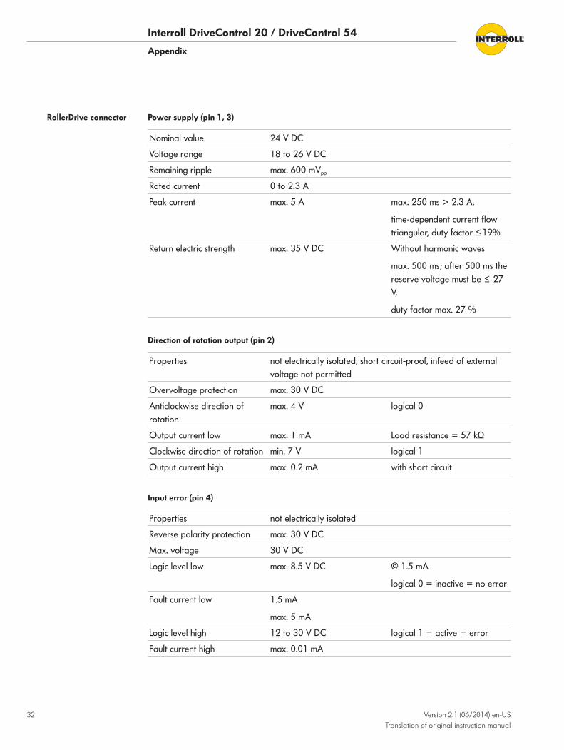
Power supply (pin 1, 3)
Nominal value 24 V DC
Voltage range 18 to 26 V DC
Remaining ripple max. 600 mVpp
Rated current 0 to 2.3 A
Peak current max. 5 A max. 250 ms > 2.3 A,
time-dependent current flow triangular, duty factor ≤19%
Return electric strength max. 35 V DC Without harmonic waves
max. 500 ms; after 500 ms the reserve voltage must be ≤ 27 V,
duty factor max. 27 %
Direction of rotation output (pin 2)
Properties not electrically isolated, short circuit-proof, infeed of external voltage not permitted
Overvoltage protection max. 30 V DC
Anticlockwise direction of rotation
max. 4 V logical 0
Output current low max. 1 mA Load resistance = 57 kΩ
Clockwise direction of rotation min. 7 V logical 1
Output current high max. 0.2 mA with short circuit
Input error (pin 4)
Properties not electrically isolated
Reverse polarity protection max. 30 V DC
Max. voltage 30 V DC
Logic level low max. 8.5 V DC @ 1.5 mA
logical 0 = inactive = no error
Fault current low 1.5 mA
max. 5 mA
Logic level high 12 to 30 V DC logical 1 = active = error
Fault current high max. 0.01 mA
RollerDrive connector
Interroll DriveControl 20 / DriveControl 54Appendix
Version 2.1 (06/2014) en-US Translation of original instruction manual
33
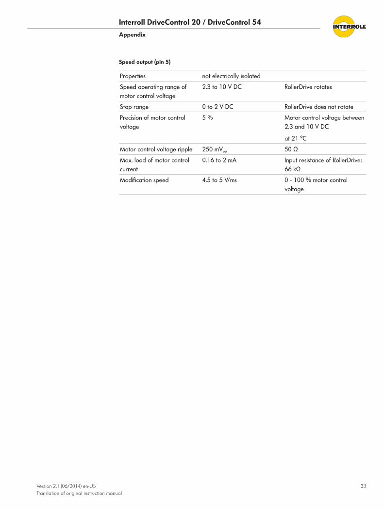
Speed output (pin 5)
Properties not electrically isolated
Speed operating range of motor control voltage
2.3 to 10 V DC RollerDrive rotates
Stop range 0 to 2 V DC RollerDrive does not rotate
Precision of motor control voltage
5 % Motor control voltage between 2.3 and 10 V DC
at 21 °C
Motor control voltage ripple 250 mVpp 50 Ω
Max. load of motor control current
0.16 to 2 mA Input resistance of RollerDrive: 66 kΩ
Modification speed 4.5 to 5 V/ms 0 - 100 % motor control voltage

Interroll DriveControl 20 / DriveControl 54Appendix
34 Version 2.1 (06/2014) en-US Translation of original instruction manual
Declaration of Conformity
The manufacturer:Interroll Engineering GmbH Hoeferhof 16 D - 42929 Wermelskirchen Germany
hereby declares with sole responsibility that the product range
• DriveControl 20 • DriveControl 54
meets the requirements of the directives and standards listed below:
Applicable EC directives: • Machinery Directive 2006/42/EC • RoHS Directive 2002/95/EC
Applicable harmonized standards: • DIN EN ISO 12100:2011-03 "Safety of machinery - Basic concepts - risk assessment and
reduction"
Person authorized to prepare the technical documents: Interroll Engineering GmbH, Hoeferhof 16, D - 42929 Wermelskirchen, Germany
Wermelskirchen – 30 June 2014
Armin Lindholm
(Managing Director)
(This declaration of conformity can be obtained at www.interroll.com, if needed.)

DriveControl 20 / DriveControl 54
Version 2.1 (06/2014) Translation of original instruction manual
35

For your local contacts please visit interroll.com/contacts
©copyright
Version 2.1 (06/2014) Translation of original instruction manual