instruction manual - hobbicomanuals.hobbico.com/gpm/gpma0535-manual.pdf · instruction manual tm....
TRANSCRIPT

WARRANTYGreat Planes® Model Manufacturing Co. guarantees this kit to be free from defects in both material and workmanship at the date ofpurchase. This warranty does not cover any component parts damaged by use or modification. In no case shall Great Planes'liability exceed the original cost of the purchased kit. Further, Great Planes reserves the right to change or modify this warrantywithout notice.
In that Great Planes has no control over the final assembly or material used for final assembly, no liability shall be assumed nor acceptedfor any damage resulting from the use by the user of the final user-assembled product. By the act of using the user-assembled product,the user accepts all resulting liability.
If the buyer is not prepared to accept the liability associated with the use of this product, the buyer is advised to return thiskit immediately in new and unused condition to the place of purchase.
READ THROUGH THIS MANUAL BEFORESTARTING CONSTRUCTION. IT CONTAINSIMPORTANT WARNINGS AND INSTRUCTIONSCONCERNING THE ASSEMBLY AND USE OFTHIS MODEL.
SPELP02 for Kit GPMA0535 V1.0© Copyright 1999
P.O. Box 788 Urbana, IL 61803 (217) 398-8970www.greatplanes.com
INSTRUCTION MANUAL
TM
WARNING! THIS IS NOT A TOY!This R/C kit and the model you will build is not a toy! It iscapable of serious bodily harm and property damage. IT ISYOUR RESPONSIBILITY AND YOURS ALONE - to buildthis kit correctly, to properly install all R/C components andto test and fly the model only with experienced, competenthelp in accordance with all safety standards and commonsense as set down in the Academy of Model AeronauticsSafety Code. It is suggested that you join the AMA tobecome properly insured before you attempt to fly thismodel. IF YOU ARE JUST STARTING R/C MODELING,CONSULT YOUR LOCAL HOBBY SHOP OR WRITE TOTHE ACADEMY OF MODEL AERONAUTICS TO FIND ANEXPERIENCED INSTRUCTOR IN YOUR AREA.
Academy of Model Aeronautics
5151 East Memorial DriveMuncie, IN 47302-9252Tele. (800) 435-9262Fax (765) 741-0057
Or via the Internet at: http://www.modelaircraft.org
Thank you for purchasing the Great Planes SPIRIT ELITEsailplane. Soaring offers a freedom that no other type offlying can provide! With a little practice and some help frommother nature, you will be able to defy gravity and enjoyflights that can last for hours.
The SPIRIT ELITE’S wing uses the SA7035 airfoil at the rootblending to the SA7036 airfoil at the tip. This combinationgives the aircraft a superior Lift to Drag (L/D) ratio withoutstanding performance in higher wind conditions. Thisadvanced wing design incorporates flaps and ailerons toprovide the ultimate in control when using computer radiomixing functions.
Take your time and follow directions to end up with awell-built model that is straight and true.
❏ Radio having at least 4 channels (5 channels requiredfor crow mixing)
❏ Iron-on Covering Material (2 rolls)❏ Latex Foam Rubber Padding (1/4” thick) (HCAQ1000)❏ Hi-start or other Launching Device (DYFP8302)❏ BB’s or Lead Shot for Balancing
❏ 2 oz. Thin CA Adhesive (GPMR6003)❏ 1 oz. Medium or Thick CA Adhesive (GPMR6008)❏ 5-Minute Epoxy (GPMR6045)❏ Hand or Electric Drill❏ Sealing Iron (TOPR2100)❏ Heat Gun (TOPR2000)❏ Razor Saw❏ Hobby Knife, #11 Blades❏ Screw Drivers❏ T-Pins (HCAR5100)❏ Straightedge❏ Sandpaper (coarse, medium, fine grit)*❏ Easy-Touch™ Sander (GPMR6170)❏ Plan Protector or Wax Paper (GPMR6167)❏ Lightweight Balsa Filler (HCAR3401)❏ 10-24 Tap, Tap Wrench
The SPIRIT ELITE kit has two different wing options: astraight wing or a polyhedral wing. The straight wing is forthe more experienced sailplane pilot. It allows bettercoordinated turn efficiency and much better handling incross winds. The polyhedral wing has more stability, turnstighter with rudder, and is generally easier to fly. If you are anovice sailplane pilot we recommend you build thepolyhedral option.
BALSA BASSWOOD PLYWOOD
1. Unroll the plan sheet. Reroll the plan inside out and let ituncurl. This will help the plan lie flat.
2. Remove all parts from the box. Identify each part bycomparing it with the plan, parts list and die-cut parts page.Write the part number or size on each piece to avoidconfusion later. Use the die-cut patterns shown on page 3to identify and mark the die-cut parts.
3. If any of the die-cut parts are difficult to remove, use ahobby knife to free them. Use your sanding block to lightlysand the edges to remove any die-cutting irregularities.
Get Ready to Build
Types of Wood
WING OPTIONS
Supplies & Tools Needed
Other Items Required
INTRODUCTION
PROTECT YOUR MODEL,YOURSELF & OTHERS
2

3
DIE-CUT PATTERNS

Step 8
Step 6
Step 4
Step 2
Step 7
Step 5
Step 3
Step 1
ASSEMBLE THE TAIL
4
Cover the stabilizer and elevatorplan with Great Planes PlanProtector or wax paper.
Medium (When you see this symbol use the suggested CA.)
(When you see this symbol use the suggested CA.)
Thin
Thin
Thin
Thin
Step 16
Step 14
Step 12
Step 10
Step 15
Step 13
Step 11
Step 9
5
Thin Thin
Thin
Thin
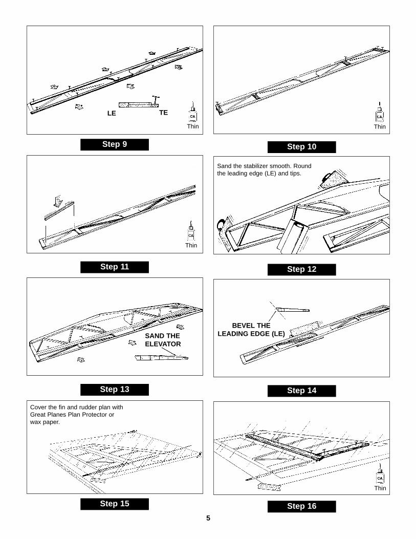
LE
SAND THEELEVATOR
BEVEL THE LEADING EDGE (LE)
TE
Sand the stabilizer smooth. Roundthe leading edge (LE) and tips.
Cover the fin and rudder plan withGreat Planes Plan Protector orwax paper.

Step 22
Step 20
Step 18
Step 23
Step 21
Step 19
Step 17
6
Thin Thin
Thin
Thin
Sand the fin and rudder smooth.Round the LE of the fin.
SAND THE RUDDER TO A TAPER
Step 8
Step 6
Step 4
Step 2
Step 7
Step 5
Step 3
Step 1
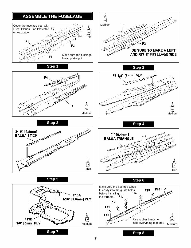
ASSEMBLE THE FUSELAGE
7
Make sure the pushrod tubesfit easily into the guide holesbefore installingthe formers.
Use rubber bands tohold everything together.
Thin
Thin Thin
Medium
Medium Medium
Medium Medium
Make sure the fuselagelines up straight.
Cover the fuselage plan with Great Planes Plan Protectoror wax paper.

Step 16
Step 14
Step 12
Step 10
Step 15
Step 13
Step 11
Step 9
8
Make sure the three punchmarks on F9, face the insideof the fuselage.
Use rubber bands to hold thefuselage together. Make surethe fuselage is straight andthen glue.
Thin
Thin Thin
Medium Medium
Make sure the fuselageis straight before gluing.
Sand entire fuselage smooth.
Round corners as shown on plan.Trim off excess.
Slide in from back.

9
Glue and clamp the wing joinertogether using 30-minute epoxy.Wipe off any excess epoxy beforeit cures.
Cover the wing plan withGreat Planes Plan Protectoror wax paper.
1/16" [1.6mm] PLYWING JOINERS
1/16" [1.6mm] PLYJOINER CAPS
ALUMINUM JOINER(Clean with alcohol)
Step 1
Step 2
BUILD THE WING

10
1/8" [3.2mm ]PLY JOINER BOX
W23
Step 3
Step 4
Step 5
Cut the 1/8" x 3/4" x 12-1/2"[3.2mm x 19mm x 317mm]plywood to make the joiner box parts
Position the 1/8" x 5/16" x 40"[3.2mm x 8mm x 1016mm]spars over the plan.Cut the spars at rib 9.
Leave1/4" [6.4mm]overhang.
Cut the W23 balsashear web at rib 9.

11
SPAR
W8
W7W6
W5W4
W23
3/16" [4.8mm] SQUAREBALSA RIB JIGS
W2A
W2B
W3B
W3A
1/8" [3.2mm] JOINERBOX FRONT
1/8" [3.2mm] JOINERBOX AFT
Step 6
Step 7
Step 8
Shim the spar up from thetable using 1/16" [1.6mm]balsa. (Use leftover piecesfrom the rib die sheets.)
Use pieces of the 3/16" x 3/16"balsa sticks as rib jigs to holdthe ribs in place for the stepsthat follow.
Clamp the 1/8" [3.2mm] joinerbox front and joiner box aft tothe spars.
Add ribs 2A&B.Add ribs 3A&B.
BUILD THEINBOARD PANEL
Thin
DO NOT GLUE THEJOINER BOX YET!

12
70%ISOPROPYLALCOHOL
Step 10
Use 30-minute epoxy to glue thejoiner box to the spars.
Before the glue cures, insert thewing joiner several times to get agood fit and to push out excessglue. When satisfied, pull out thejoiner and wipe clean.
Coat the wing joiner withisopropyl alcohol so theepoxy won't stick.
DGRDGR
W1BW1A
Align the rib between thedashed lines on the plan.
Align the rib between thedashed lines on the plan.
Use the dihedral gauge toset the angle.
1/16" X 3/8" X 42"[1.6mm X 9.5mm X 1067mm]
SUB LE 1/8" X 1/2" X 42"[3.2mm X 12.7mm X 1067mm]
BALSA WING TE
Step 9
Center the TE on the ribs.
Line up the LE.
Step 11 Step 12
Thin
Thin Thin

13
1/16" X 3" X 24"[1.6mm X 76mm X 610mm]
BALSA SHEET
1/16" X 3/8" X 42"[1.6mm X 9.5mm X 1067mm]
BALSA TE SHEETINGStep 15
The sheeting should line upwith the back edge of the spar.
Make sure the structure staysflat on the table.
Fill in any gaps with1/16" [1.6mm] balsa.
Sand the sheetingso it doesn’t bulgeat the cloth.
3/16" X 3/8" X 5-1/2"[4.8mm X 9.5mm X 140mm]
BASSWOOD RAILS2-3/4" [70mm]
2-3/4" [70mm]
Step 16
DGP
W9B
W9A
FIBERGLASSCLOTH
POLYHEDRAL WINGUse the polyhedral gaugeonly if you are buildingthe polyhedral wing.
Cut the fiberglass cloth into four 4” [100mm] pieces.Attach part of the fiberglass cloth to the sparsusing thin CA. You will finish this step after you remove the panel from the table.
STRAIGHT WINGAlign ribs W9A and W9B
straight up and downover the plan.
Step 13 Step 14
Thin
Thin
Mediumor
aliphaticwoodglue
Medium
Cut the rails in half.

14
1/16" X 3" X 24"[1.6mm X 76mm X 610mm]
BALSA SHEET
W20 1/16" [1.6mm]PLY HATCH
Step 17
Use the ply hatch as atemplate for cutting thehole for the flap servo.
Cut from 1/16" X 3" X 24"[1.6mm X 76mm X 610mm]
BALSA SHEET
Step 18
Step 19
Remove the wing from thetable. Cut off the jig tabsand sand smooth.
Step 20
Wrap the fiberglass cloth tightly around the joinerbox and glue it in place. Cut off any excess.
1/16" X 3" X 24"[1.6mm X 76mm X 610mm]
BALSA SHEET
Step 21
Glue the top sheeting in place.
1/16" X 3/8" X 42"[1.6mm X 9.5mm X 1067mm]
BALSA SHEETING
Medium Medium
Thin
Mediumor
aliphaticwoodglue
The cloth will cause thesheeting to bulge. sand thesheeting to compensate.

15
1/16" X 3" X 24"[1.6mm X 76mm X 610mm]
BALSA SHEET
Step 22
Install the top center sheeting.
Step 23
Sand the root and theouter ribs smooth.
Bevel the leading edge so the balsawill follow the shape of the rib.
Cut 2-1/2" [63.5mm] from one of the 1-3/4" x 24"[44.4mm x 610mm] balsa triangles and glue inplace at the wing root.
Trim off and sand the leadingedge smooth.
Finish the slot in W1Afor the wing dowel.
Epoxy the wingdowel and W1Cto the wing root.
Step 24 Step 25
Medium
16
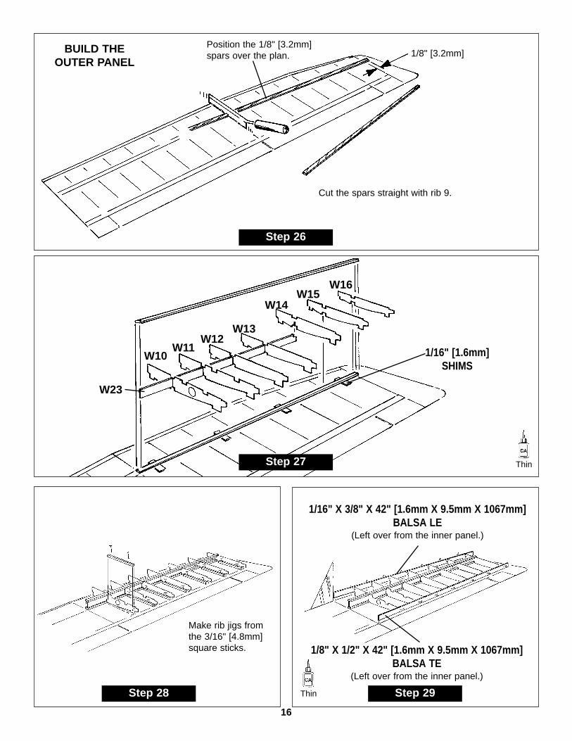
Step 26
Cut the spars straight with rib 9.
Position the 1/8" [3.2mm]spars over the plan. 1/8" [3.2mm]BUILD THE
OUTER PANEL
Step 27
W11W10
W23
W12W13
W14W15
W16
1/16" [1.6mm]SHIMS
Make rib jigs fromthe 3/16" [4.8mm]square sticks.
Step 28 Step 29
1/16" X 3/8" X 42" [1.6mm X 9.5mm X 1067mm]BALSA LE
(Left over from the inner panel.)
1/8" X 1/2" X 42" [1.6mm X 9.5mm X 1067mm]BALSA TE
(Left over from the inner panel.)
Thin
Thin
17
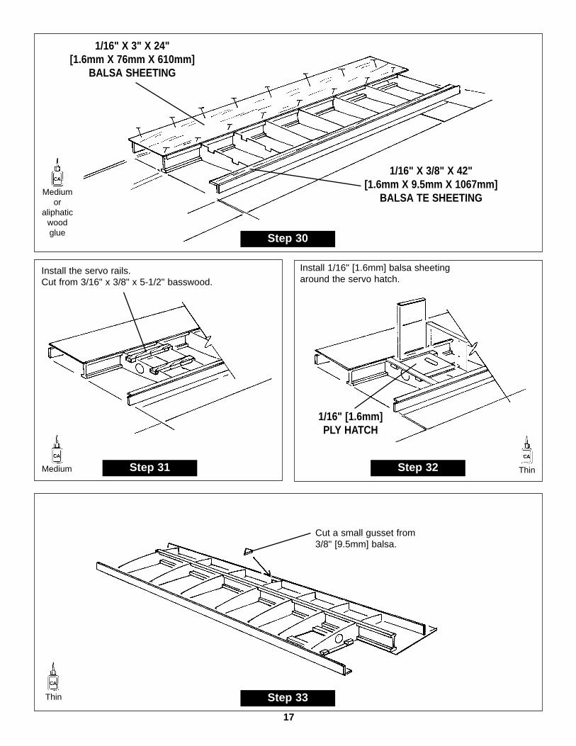
Step 30
1/16" X 3" X 24"[1.6mm X 76mm X 610mm]
BALSA SHEETING
1/16" X 3/8" X 42"[1.6mm X 9.5mm X 1067mm]
BALSA TE SHEETING
1/16" [1.6mm]PLY HATCH
Install the servo rails.Cut from 3/16" x 3/8" x 5-1/2" basswood.
Install 1/16" [1.6mm] balsa sheetingaround the servo hatch.
Step 31 Step 32
Step 33
Cut a small gusset from3/8" [9.5mm] balsa.
Mediumor
aliphaticwoodglue
Medium Thin
Thin

18
W9A
W9B
Trim excess sheeting.
Step 34 Step 35
1/16" X 3" X 24"[1.6mm X 76mm X 610mm]
BALSA SHEETING
Step 36
1/16" X 3/8" X 42"[1.6mm X 9.5mm X 1067mm]
BALSA TE SHEETING
Step 37
Trim off the excess sheetingand sand smooth.
Sand the root andtip ribs smooth.
Thin
19
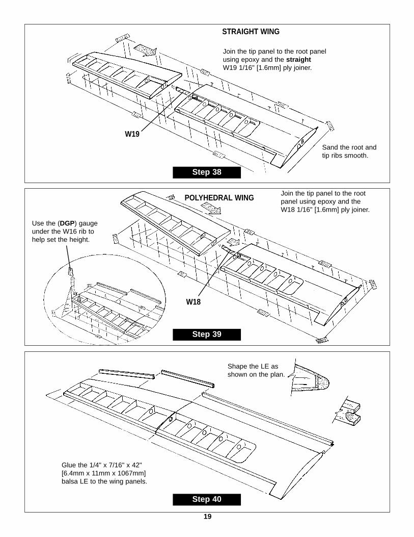
Step 38
Join the tip panel to the root panelusing epoxy and the straightW19 1/16" [1.6mm] ply joiner.
Sand the root andtip ribs smooth.
W19
STRAIGHT WING
Step 40
Shape the LE asshown on the plan.
Glue the 1/4" x 7/16" x 42"[6.4mm x 11mm x 1067mm]balsa LE to the wing panels.
Step 39
Join the tip panel to the rootpanel using epoxy and theW18 1/16" [1.6mm] ply joiner.
Use the (DGP) gaugeunder the W16 rib tohelp set the height.
W18
POLYHEDRAL WING
20
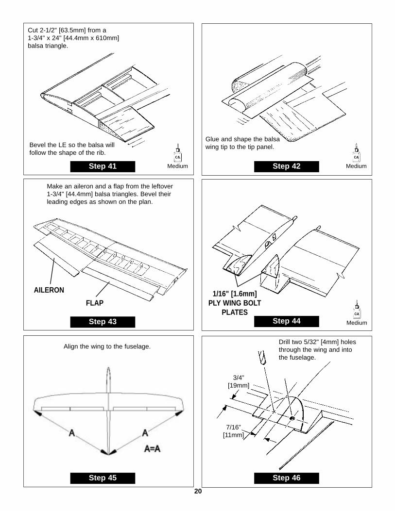
Bevel the LE so the balsa willfollow the shape of the rib.
Glue and shape the balsawing tip to the tip panel.
Cut 2-1/2" [63.5mm] from a 1-3/4" x 24" [44.4mm x 610mm]balsa triangle.
Step 41 Step 42
1/16" [1.6mm] PLY WING BOLT
PLATES
Make an aileron and a flap from the leftover 1-3/4" [44.4mm] balsa triangles. Bevel theirleading edges as shown on the plan.
Step 43 Step 44
Drill two 5/32" [4mm] holesthrough the wing and intothe fuselage.
Align the wing to the fuselage.
3/4” [19mm]
7/16”[11mm]
Step 45 Step 46
AILERON
FLAP
Medium Medium
Medium

21
Carefully tap the two holes. Reinforce thethreads with thin CA and retap.
Enlarge the holesin the wing.
Step 47 Step 48
10-24 TAP
Build the canopy.
Glue the plywood C2 doublerto C1 balsa canopy base.
Glue the canopy partstogether. Be carful not toglue them to the fuselage.
Trim and sand C1 andC3 to fit your
Step 1 Step 2
C1
C1
C3
C4
C2
Drill a 1/8" [3mm] hole into the nose block. Glue inthe 1/8" x 1" [3mm x 25.4mm] dowel into the canopybase. Do not glue the dowel to the fuselage.
Step 3 Step 4
BALSA NOSE BLOCK
1/8" [3mm]DRILL BIT
Medium
Thin
Thin
FINISHING

22
Trim the plastic canopy to fit the canopyframe and fuselage.
Sand the nose block to shape.(See plan)
Step 5 Step 6
Drill 3 holes in F9 - 1/16"[1.6mm] ply tow hook mount.
Press in the threeblind nuts.
Step 7 Step 8
SMALL RUBBERBAND
4-40 TOWHOOK
CENTERLINEMARKING
TOOL
4-40WASHER
4-40 NUT
# 2 X 3/8" [9.5mm] SCREW
1/8" [3mm]DRILL BIT
Mark a centerline on the finand rudder.
Carefully cut hingeslots at the locationsshown on the plan.
Cut two 3/4" x 1" [19mm x 25.4mm] hingesfrom the 2" x 9" [50.5 x 228.5mm] hinge strip.
Step 9 Step 10
HINGE THE RUDDER
Medium
DO NOTGLUEYET.
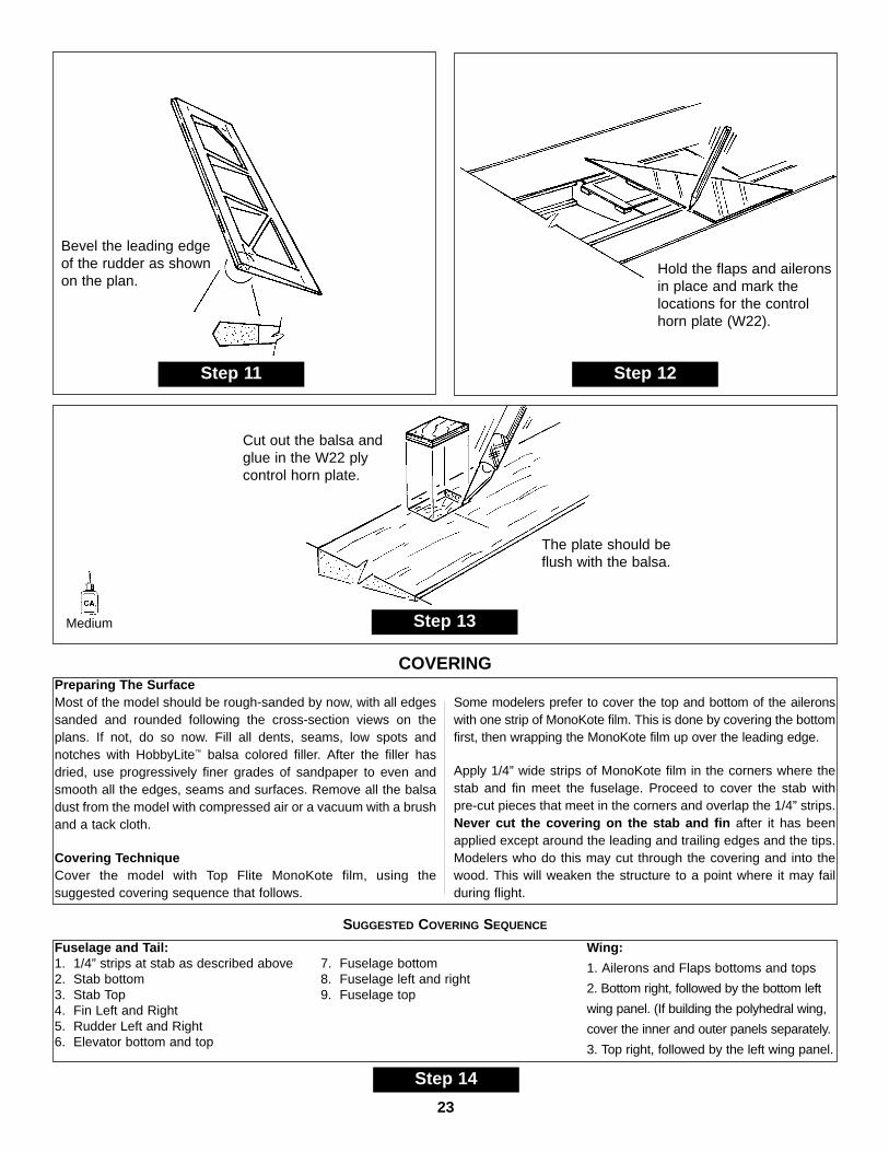
Fuselage and Tail:1. 1/4” strips at stab as described above2. Stab bottom3. Stab Top4. Fin Left and Right5. Rudder Left and Right6. Elevator bottom and top
7. Fuselage bottom8. Fuselage left and right9. Fuselage top
Wing:
1. Ailerons and Flaps bottoms and tops
2. Bottom right, followed by the bottom left
wing panel. (If building the polyhedral wing,
cover the inner and outer panels separately.
3. Top right, followed by the left wing panel.
23
Bevel the leading edgeof the rudder as shownon the plan.
Hold the flaps and aileronsin place and mark thelocations for the controlhorn plate (W22).
Step 11 Step 12
Step 13
Cut out the balsa andglue in the W22 plycontrol horn plate.
The plate should beflush with the balsa.
Step 14
Preparing The SurfaceMost of the model should be rough-sanded by now, with all edgessanded and rounded following the cross-section views on theplans. If not, do so now. Fill all dents, seams, low spots andnotches with HobbyLite™ balsa colored filler. After the filler hasdried, use progressively finer grades of sandpaper to even andsmooth all the edges, seams and surfaces. Remove all the balsadust from the model with compressed air or a vacuum with a brushand a tack cloth.
Covering TechniqueCover the model with Top Flite MonoKote film, using thesuggested covering sequence that follows.
Some modelers prefer to cover the top and bottom of the aileronswith one strip of MonoKote film. This is done by covering the bottomfirst, then wrapping the MonoKote film up over the leading edge.
Apply 1/4” wide strips of MonoKote film in the corners where thestab and fin meet the fuselage. Proceed to cover the stab withpre-cut pieces that meet in the corners and overlap the 1/4” strips.Never cut the covering on the stab and fin after it has beenapplied except around the leading and trailing edges and the tips.Modelers who do this may cut through the covering and into thewood. This will weaken the structure to a point where it may failduring flight.
SUGGESTED COVERING SEQUENCE
COVERING
Medium

24
STABELEVATOR
MONOKOTE ORSTRONG TAPE HINGE
Fold back the elevator andapply monokote or strongtape to the underside.
Step 17Step 16
Installing CA Hinges for the Rudder
The Rudder in this kit is attached using two CA hingeswhere shown on the plans.
It is best to leave a very slight hinge gap, rather than closing it up tight. This will prevent the Glue from wicking alongthe hinge line. Insert a small pin through the center of each hinge to keep the hinge centered while you install thecontrol surfaces.
Step 15
DRILL A 3/32" HOLE1/2" DEEP, IN CENTER
OF HINGE SLOT
TEMPORARY PINTO KEEP HINGE
CENTERED
ASSEMBLE, THEN APPLY 6 DROPSOF THIN CA TO CENTER
OF HINGE, ON BOTH SIDES

25
MONOKOTE ORSTRONG TAPE HINGE
Use a triangle to align thefin 90o to the stab. Glue inplace with epoxy.
Position the fin so it is straight with thefuselage. Remove the covering wherethe fin rests on the fuselage.
Install the flaps andailerons with MonoKoteor strong tape hinge.
Step 20Step 19
# 2 X 3/8" [9.5mm]FLAT HEAD SCREWS
Cut servo blocks from the 3/16" x 3/8" x 2"[4.8mm x 9.5mm x 50.8mm] basswood.
Drill small pilotholes for theservo screws.
Drill pilot holesfor the screws.
Install the servosto the blocks.
Cover the hatchwith Monokote.
Glue in placewith MediumCA or epoxy.
Step 22Step 21
A=A AAA A
A=A
Step 18
Align the stabilizer so that it is parallelwith the wing.
When satisfied with the fit,glue in place with epoxy.

26
Step 24
1" [25.4mm] THREADED WIRE
INNER PUSHROD TUBE
NYLON CLEVIS ANDCLEVIS RETAINER
Step 25
1" [25.4mm] THREADED WIRE
METAL CLEVIS
NYLON BACKPLATE
NYLON CONTROL HORN
2-56 X 3/8" [9.5mm] BOLT2-56 X 3/8" [9.5mm] BOLT
Wrap the receiver andbattery in foam.
Line up the control hornswith the pushrods. Attachthe control horns to theelevator and rudder.
Install the switch inside thefuselage, next to the receiver.
Step 23

NOTE: This section is VERY important and must not beomitted! A model that is not properly balanced will beunstable and possibly unflyable.
1. The balance point (Center of Gravity) is 3-1/4” (82mm)from the Leading edge. This is the balance point at whichyour model should balance for your first flights. Later, youmay wish to shift the balance up to 1/2”(13mm) behind thispoint to change the flying characteristics. Moving the CGforward will add stability but it will decrease the overallperformance of the sailplane. Moving the balance backmakes the model more agile with a lighter and snappier“feel” and improves the sailplane’s response to air currents.However, it will also make the model less stable and cancause the sailplane to “tuck under” or dive when its flyingspeed increases.
2. With the wing attached to the fuse, and all parts of themodel installed (ready to fly), lift the model by picking it upwith your fingertips. If the tail drops when you lift, the modelis “tail heavy” and you must add weight to the nose tobalance. If the nose drops, it is “nose heavy” and you mustadd weight to the tail to balance. The model should hang witha slight nose down attitude. Add BB’s or lead to the nose.
1. The tow hook should be in the front hole for the firstflights. After the first flights the tow hook can be moved backto the middle hole for most flying conditions. For contestflying you may want to try the rear hole as it can helpachieve a higher launch. But be careful as the sailplane willbe less stable and more apt to “Pop Off’ the line.
If you are not thoroughly familiar with the operation of R/Cmodels, ask an experienced modeler to check to see youhave the radio installed correctly and all the control surfacesdo what they are supposed to.
TRIMMING FLIGHTS
It is a good idea to do a couple of trim flights before eachflying session to make sure the plane is still in trim and theradio is working properly.
Hold the SPIRIT ELITE under the wing with the nosepointed slightly down and directly into the wind. Launch themodel with the wings level and the nose pointing at a spoton the ground about 50 feet in front of you. If the sailplaneis launched with the nose up or launched too hard it willclimb a few feet, stall and fall nose first straight down. Withthe nose pointed down slightly the sailplane will acceleratedown until it picks up enough flying speed, then level off andglide forward. Adjust the trims on your transmitter to get theplane to fly straight ahead in a smooth glide path.
FLYING
TOW HOOK LOCATION
Use these control throws for your first flights.
ELEVATOR: 1/2” (13mm)
RUDDER: 2” (50mm)
FLAPS: 1-3/8” (35mm) down
AILERONS: 3/4” (19mm) up, 3/8”(9.5mm) down
CONTROL SURFACE THROWS
BALANCE THE MODEL
27

HI-START LAUNCH
A hi-start is the most common way to launch your SPIRITELITE. Follow the directions that came with the hi-start andlay it out directly into the wind. Place the stake at the farupwind edge of the flying field so the parachute will blowback onto the flying field.
Hook the parachute up to the tow hook. Pull the plane backapproximately twice as far as the rubber is long or whateverthe hi-start instructions recommend.
Hold the plane above your head with the wings level and thenose pointed slightly up and directly into the wind. Give theplane a push forward to get it flying and it will climb up likea kite. You should not have to touch the elevator during thelaunch. Use the rudder stick to keep it going straight up.You will find the ailerons are not very responsive during thefirst part of the launch. As the rubber relaxes the plane willfly off the hi-start.
FIRST FLIGHTS
Use these flights to get the “feel” of the controls and theSPIRIT ELITE’S flying characteristics. Adjust the trims onyour transmitter (a little at a time) until the plane will flystraight and level with the transmitter sticks in their neutralpositions. If you built the polyhedral wing, rudder alone isenough to perform smooth turns. If you built the straightwing, you will need to coordinate ailerons with rudder forsmooth turns.
The SPIRIT ELITE is a very gentle plane that flys well inlight to moderate winds. Practice coordinating ailerons andrudder until you can get a tight turn that is relatively flat.Bank the sailplane with rudder and ailerons first, then addelevator to pull it around. When setting up to land, point thenose into the wind just downwind of where you want to land.Line up with your landing spot and slowly feed in flaps (orCrow). Add more or less flaps to control your descent angleand speed so you end up hitting the spot.
There are several types of mixing the Spirit Elite can takeadvantage of if you have a “computer radio”.
Launch Camber: Lowering the flaps and ailerons during thelaunch will produce a steeper climb giving you better altitude.A good place to start is about 15 degrees of flap and 5degrees of aileron drop (The flaps will drop about three timesmore than the ailerons). This automatically puts somewashout in the wing which adds stability for arrow straightlaunches. If you don’t have a switch for launch camber, justuse the flaps for launch.
Crow: This is used to lose altitude quickly and to control yourglide for spot landings. This mixing is tied to the flap stick(throttle)and allows the ailerons to come up as the flaps drop.Be sure to use plenty of aileron differential when usingCROW mixing because the ailerons become less effective atvery high angles of deflection. Also use maximum ruddercoupling at full CROW. If you don’t have CROW capabilitiesjust use flaps and make sure you have full rudder throw whenthe flaps start coming down. It is a good idea to get lined upon the spot before dropping the flaps very much because therudder will become sluggish with the flaps down at slowspeeds. Note: You will need to mix in a little down elevatorwith the flaps to keep the plane tracking straight.
Aileron/Rudder Coupling - This is used to allow thesailplane to make efficient, non-slipping, non-skidding turns.You will need to experiment to find the proper amount ofthrow required to do this but 1” (25mm) of rudder throw at fullaileron is probably a good place to start.
Elevator/Camber Coupling - This is a neat type of mixingallows the TE (ailerons and flaps) to respond to the elevator.When properly set up, this can be very useful when floatingaround in light air or when trying to thermal very tightly. Thismixing can change the flying characteristics of the plane sostart off small and get used it. A good place to start would be1/8” (3mm) of TE drop at full up elevator.
Controlling the Wing Trailing Edge (Camber): The wingcamber is usually controlled by a 3-position switch. The traditionalway of setting this switch is to have: the middle position set toneutral camber, one direction for reflex (the entire TE raises about1/16”( 1.5mm)) and the other direction for positive camber (theentire TE drops about 3/32”(2.5mm)). This way of programmingthe switch is great for good thermal-days or days with a lot of windwhere you might need the reflex capability for zooming up wind.The other way we set this switch is to have the “back” position forneutral camber, the middle position for a slight amount of positivecamber (1/32”(1mm) - 1/16”(2mm)), and the forward position formore positive camber (3/32”2.5mm - 1/8”(3mm)). The middleposition can be used once good air is located or when trying togain a few extra seconds of air time. Normally the L/D will not beas great as neutral camber but the sailplane will float better. Theforward position is when the sailplane is low and encounters lift,don’t panic, just hit the switch. The SPIRIT ELITE will really slowup and will thermal “on a dime”. This set-up is great for durationtype flying without a lot of wind.
ADVANCED FEATURES
28

Thermals are a natural phenomenon that happen outside,by the millions, every single day of the year. Thermals areresponsible for many things including forming several typesof clouds, creating breezes, and distributing plant seeds andpollen. If you have ever seen a dust devil (which is nothingmore than a thermal that has picked up dust), you haveseen a thermal in action. Their swirling action is very similarto that of a tornado but much gentler. Most thermals haveupdrafts rising 200-700 feet per minute but have beenknown to produce updrafts of over 5,000 feet per minuteThese strong thermals can rip a plane apart or carry theplane out of sight before the pilot can get out of the updraft.
Thermals are formed by the uneven heating of the earth andbuildings, etc. by the sun. The darker colored surfacesabsorb heat faster than the lighter colors which reflect agreat deal of the sun’s energy back into space. Thesedarker areas (plowed fields, asphalt parking lots, tar roofs,etc.) get warmer than the lighter areas (lakes, grassy fields,forests, etc.). This causes the air above the darker areas tobe warmer than the air over the lighter areas and the morebuoyant warm air rises as the cooler, denser air forces itsway underneath the warmer air. As this warm air is forcedupward it contacts the cooler air of the higher altitudes andthis larger temperature difference makes the thermal risequicker. The thermal is gradually cooled by the surroundingcooler air and its strength diminishes. Eventually thethermal stops rising and any moisture contained in the oncewarm air condenses and forms a puffy cumulus cloud.These clouds, which mark the tops of thermals, are usuallybetween 2000 and 5000 feet high.
As the glider approaches a thermal, the wing tip thatreaches the rising air first will be lifted before the oppositewing tip. This causes the plane to “bank” and turn away fromwhere we would like the plane to go. The best way to getback in is to continue the bank and turn 270 degreesstraight into the thermal.
When you are thermal soaring, try to fly as smoothly andstraight as possible. Trim the plane to fly in a straight lineand only touch the controls when you have to. Watch thesailplane carefully and it will tell you what it is encountering.
When the sailplane flys directly into a thermal it will eitherstart rising or stop sinking. Either case is reason enough tostart circling. Fly straight until you feel like you are in thestrongest lift, then fly a couple of seconds farther so yourcircle will be centered in the strongest lift. Thermals travelwith the wind, so be careful that you don’t get too fardownwind that you can’t get back. If you find yourself gettingtoo high, don’t dive the plane to get out of the lift. Sailplanesare very efficient aircraft and they will build up a lot of speedand could “blow up” in the rough air of a thermal. Theeasiest way to lose altitude is to apply full rudder and full upelevator. This will put the plane into a tight spin that will notover stress the airframe but it will enable it to lose altitudevery quickly. This is especially helpful if the sailplane getssucked into a cloud or it gets too high to see.
As you might expect, with all this air rising, there is also airsinking. This air is the sailplane pilot’s nightmare that canreally make soaring challenging. “Sink” is usually not asstrong as the thermals in the same area but sometimes canbe. Because of this, it is important you do not let thesailplane get too far downwind.
Watch the birds! - Thermals suck up small insects manybirds love to eat. A bunch of swallows flying around in onearea may indicate a thermal. Soaring birds (hawks, vultures,eagles etc.) are the best thermal indicators. They not onlyshow you where the thermal is but they also show youwhere the center is. These “Masters of the sky” will often flyright along with sailplanes.
Practice those landings! - Most thermal contests are wonor lost during the landing. Establish a particular landingpattern and try to stick to it for all landings. Learn to shiftyour pattern to account for the wind and particular flyingfield characteristics. Flaps can be very useful during contestlandings. They allow you to bring the sailplane in for alanding higher or faster than normal to guard against anylast minute sink or gusts and dump the extra altitude andspeed at the last second. They can also be used to help
THERMAL SOARINGFACTS ABOUT THERMALS
29

control your skid. Flaps will stop the plane from sliding alittle quicker. You can also “steer” the plane while it is slidingalong the ground. Don’t expect to be able to “horse itaround” but you can gain valuable inches by using therudder to guide it towards the spot as it slides to a stop. Bevery careful not to “ground loop” the plane since you willlose your landing points if the plane flips over.
To be able to slope soar, you need a slope with a smoothpiece of land (or water) out in front of it and a breezeblowing pretty close to straight up the slope. The higher andsteeper the hill or cliff the better. Also the larger andsmoother the land out in front the better. The air flowingtowards the hill, is forced up and can generate a very largearea of lift. Behind the hill is a large area of turbulent air thatcan be very dangerous to try to fly in. The faster the wind isblowing the stronger the lift and turbulence will be.
To fly off a slope, stand near the edge and throw thesailplane (nose down) into the wind. As the sailplane flys outinto the “band” of lift it will begin to gain altitude. Turn and flyparallel to the slope and make all of your turns into the wind(especially when you are close to the slope). You will besurprised at the altitude you can gain just from slope lift.Thermals will often be “popped loose” by these slopes. Ifyou catch a thermal and follow it downwind, be very carefulto stay high enough to make it back to the slope withoutflying through the turbulent air. Landings can be very trickyon some slopes. On gentle slopes you can often fly veryclose to the top of the slope and “slide” into the top of theslope without encountering any turbulent air. On steeperslopes you may have to be a little more aggressive to getthe plane out of the lift. In any case it is a good idea to planyour landing before you launch your plane.
In strong wind conditions, you may want to add ballast(weight) to the sailplane to increase its wing loading whichincreases its normal flying speed. Increasing the weight ofyour sailplane does not change its “glide ratio” but it doesmake it fly faster which makes it sink a proportional amountfaster. Because of this faster sink rate, you need to be verycautious when ballasting for a thermal contest. In durationtype contests only use ballast on very windy days that also
have a lot of thermal activity. Center the weight directly onthe center of gravity of the plane so you can add ballastwithout having to re-balance the plane. When learning toballast your plane, start out small and work your way up.
Have fun and Good lift!!
BALLAST
SLOPE SOARING
30

Spirit™ 100.
Keep your costs in check and still enjoy high-performancefeatures with the Great Planes Spirit 100. Interlockingconstruction makes it beginner-easy to build. Two wingoptions—the proven Spirit wing with S-3010 airfoil, or anadvanced version with a highly efficient S-7037 airfoil, plusflaps and ailerons for greater control—enable fliers of allskill levels to enjoy its versatile performance. The advancedwing enables experienced sailplane pilots to use crowmixing and offers complete camber-changing capability forsuperior thermalling!
• Huge 100" wingspan for extra-smoothflight!
• Two wing options in one easy-to-build kit.
• High performance without high cost.
GPMA0550Wingspan: 100 in (2530mm)Wing Area: 946 sq in (61 sq dm)Weight: 3-4 lb (1420-1840g)Wing Loading: 8-10 oz/sq ft (23-31 g/sq dm)Fuselage Length: 51.5 in (1310mm)Requires: 2-4 channel radio with 2-5 servos (use 3-channel
31
Spectra™ Electric Sailplane
Electric motor power and a 78.5" span, triple-taper wing withmodified Selig 3010 airfoil give the Spectra outstandingclimbing ability...while the model's clean, aerodynamicdesign helps you stretch your soaring times by movingeasily from thermal to thermal. The kit's easy assembly(using the photo-illustrated manual), durability and forgivingflight make it great for beginners. Includes hardware,canopy, molded cockpit, Goldfire 550 motor system and 8x4prop. Add Great Planes' scimitar style 8x4 Nylon FoldingPropeller (GPMQ1690) to minimize drag.
• A 2-meter electric that climbs from 0-500feet in 60 seconds!
• Suitable for any skill level, with easy kitassembly, smooth flight characteristics and a
durable airframe.
• Powered by an included Goldfire 550 motor system.
GPMA0540Wingspan: 78.5 in (1995mm)Wing Area: 676 sq in (43.6 sq dm)Weight: 48-52 oz (1360-1470g)Wing Loading: 10 oz/sq ft (31 g/sq dm)Fuselage Length: 38 in (965mm)Requires: 2-3 channel radio, 6-7 cell battery & charger
Perfect choices for every sailplane pilot.
Their quiet flight keeps your airfield's neighbors happy. Getting into action is clean, quick and easy. And the best reasonof all to fly a Great Planes sailplane? Their performance is awesome—right out of the box!
Extend your airtime indefinitely with a Great Planes sailplane...there's always more as close as the next thermal! Like theSpirit Elite, the Spirit 100 and Spectra both offer fast, easy assembly, made even more enjoyable by Great Planes' perfectlyinterlocking wood parts, photo-illustrated instruction manuals and premium quality hardware. Both include canopy andmolded cockpit.
BUILDING NOTES
Kit Purchased Date: _______________________
Where Purchased:_________________________
Date Construction Started: __________________
Date Construction Finished: _________________
Finished Weight: __________________________
Date of First Flight: ________________________
FLIGHT LOG
PRINTED IN USA