instruction manual for mistral 3000i centrifuge · pdf fileinstruction manual for mistral...
TRANSCRIPT

Instruction Manual
For
MISTRAL 3000i
CENTRIFUGE
READ BEFORE USE!
Models MSB300.CR2.C
MSB300.CR2.I
71100-1381-1
0206

SANYO GALLENKAMP PLC Health and Safety at Work
Sanyo Gallenkamp is required under the Health and Safety at work, etc. Act, 1974 and other UK legislation as designers, manufacturers, suppliers and importers of articles for use at work to ensure that, as far as is reasonably practicable, articles which we design, produce, supply or import are safe and without risk to health.
We are required to provide information on the safety and handling precautions to be observed when installing, operating, maintaining and servicing our products. Such advice is contained in this manual.
We are also obliged to update this information should circumstances change and to operate a system to this end.
We should also like to point out, however that you as users have an important responsibility in the provision
and maintenance of safe working practices and conditions.
Accordingly, we draw the following matters to your attention:
1. This apparatus should only be used as intended and within its design parameters by
suitably qualified and trained personnel who have read and understood the relevant
sections of this manual.
2. This manual should be readily available to such personnel at all times.
3. In addition to that which is written in the manual, normal common-sense safety precautions
must be taken at all times to avoid the possibility of accidents. Particular care is required
when working with apparatus at high temperature or pressure.
4. Installation, maintenance, repairs and servicing should only be carried out by an SANYO
Gallenkamp approved engineer, and connection to electrical supplies should only be
carried out by suitably trained personnel.
TECHNICAL SUPPORT, WARRANTY SERVICE AND MAINTENANCE
UK customers; if you are in any doubt whatsoever regarding the correct use of this apparatus, or if you require any technical data or assistance, please contact the SANYO Gallenkamp Technical Support Department at;
SANYO GALLENKAMP PLC
Monarch Way Telephone +44 (0) 1509 265265
Belton Park Fax +44 (0) 1509 269770
Loughborough E-mail: [email protected]
Leicester LE11 5XG Web Page: www.sanyogallenkamp.com
OVERSEAS CUSTOMERS: Should contact their local Sanyo Gallenkamp Distributor, details can be found on our website.
ELECTRICITY SUPPLIES: Voltage and frequency Sanyo Gallenkamp electrical apparatus is offered and labelled for one, or for a choice of two or more voltage ranges and, where necessary, different frequencies of mains supply. Sanyo Gallenkamp does not accept any responsibility for the operation of any such apparatus should it be connected to electricity supplies which are normally outside, or vary outside, the stated voltage and frequency values for which it is designed, nor for any consequential loss, damage or injury, howsoever caused.
Read This Before Use!

DECLARATION OF CONFORMITY according to EN 45 014 - ( BS 7514 )
SANYO Gallenkamp PLC. Registered Office: Monarch Way, Loughborough, Leicestershire LE11 5XG. Registered in England and Wales No. 2462454
Document no: 71100.1254.1
SANYO Gallenkamp PLC
Monarch Way, Belton Park, Loughborough, Leicestershire, LE11 5XG. U.K. Tel: +44 (0) 1509 265265 Fax: +44 (0) 1509 269770 E-Mail: [email protected] Web: www.sanyogallenkamp.com

Thank you for buying a MSE Centrifuge. Please read this operating manual before using your centrifuge; it will provide you and your colleagues with useful information on all aspects of the equipment. As our customer, we should like to ensure that you are totally satisfied at all times. Do not hesitate to contact:
Sanyo Gallenkamp - your views are very important to us.
Sanyo Gallenkamp plc

ELECTRICITY SUPPLY
Before connecting this apparatus to the electricity supply, check the information given on the rating plate and ensure that; A) Your supply is single phase a/c. (alternating current) of the stated frequency with neutral nominally at earth potential. B) Your supply voltage is within the stated range. C) The current rating is within the capacity of your outlet. D) Your plug or electricity supply circuit is fitted with a suitable fuse.
Fuse rating 15 amp
WARNING! This apparatus must be earthed.
The wires in the mains lead are coloured in accordance with the following code;
230v 120v Live Brown Black Neutral Blue White Earth Green and Yellow Green and yellow Green and Yellow or Green to terminal marked E (Earth), G (Ground), coloured Green or Green and Yellow or marked with the Earth symbol. Blue or white wire to terminal marked N (Neutral) or Common or coloured Blue. Brown or black wire to terminal marked L (Live) or Phase or coloured brown.

SANYO GALLENKAMP PLC PRODUCT WARRANTY
Terms and Conditions We hope that you do not have the need to use the extensive warranty cover that Sanyo Gallenkamp Plc. extend to you. However should you have a problem, our prompt response is greatly helped if you have filled in and posted the pre-paid Warranty Registration Card supplied with your new equipment. Sanyo Gallenkamp Plc. give a one year warranty from the date of delivery. During this period, component parts proven to be defective in materials or workmanship will be repaired or replaced at our expense. Installation, commissioning and calibration are not covered by this warranty agreement. The Sanyo Gallenkamp Plc. approved service agent must be contacted for warranty determination and direction prior to any work being carried out. These warranties are only applicable to new products, and not second hand nor refurbished products even if repaired by Sanyo Gallenkamp Plc. Any such products are covered by separate warranty terms and conditions which will be made available on request. Replacement or repair of component parts or equipment under this warranty shall not extend the warranty to either the equipment or the component part beyond the original one year warranty period unless agreed in writing by Sanyo Gallenkamp Plc. The above warranties are extended to the original purchaser upon full invoice payment. A purchase receipt or other proof of purchase may be required before warranty service will be performed. These warranties only cover failures due to defective workmanship which occur during the normal operation of the product by the original purchaser, and not failures which result from accident, misuse, abuse, neglect, mishandling, misapplication, alteration, faulty installation, electrical power fluctuations, dust, or other environmental extremes, modification or service other than by an approved service agent or following the written authority of the manufacturer, or damage that is attributable to acts of God. Expendable items such as motor brushes, door seals, lid seals, "O" rings or lamps are excluded. Sanyo Gallenkamp Plc., or its approved service agent, reserves the right to repair defective equipment on the premises of the customer, or at a service station, at the sole discretion of Sanyo Gallenkamp Plc. or their approved agent. In the event of return to an approved service centre the customer is responsible for the safe packaging of the instrument and notification to the service centre. Neither Sanyo Gallenkamp Plc. nor its agents are responsible for any damage occurring during shipment. Specification and Material Changes:- Sanyo Gallenkamp Plc. reserves the right to supply our latest and improved models at time of shipment. Taxes:- The prices quoted do not include any taxes imposed by the State or Country in which the purchase was made. Installation:- Installation of all equipment shall be by, and at the expense of the purchaser unless stated otherwise. Access to the site, and the provision of required utilities e.g. Power, water and drainage to suitable connections, will be the responsibility of the purchaser, and at the purchaser's expense. Limitation of liability:- In no event, whether as a result of breach of contract or warranty, shall Sanyo Gallenkamp Plc. be liable for any consequential or incidental damages including, but not limited to, loss of profit or revenues, loss of use of the equipment or any associated equipment, down time costs, costs of substitute equipment, costs of labour, costs due to delays or claims of purchaser's own customers for such damages. The purchaser agrees to indemnify Sanyo Gallenkamp Plc. and to hold them harmless from any and all liability, claims, demands, actions, suits, expenses or costs, including attorney's fees relating to such consequential or incidental damages. All expressed and implied warranties, including the warranties of merchantable quality and fitness for a particular purpose, are limited to the application period of one year. Validity:- Legal rights vary from country to country and states within countries, so some or all of the exclusions or limitations listed above may not apply, but if any part of these conditions shall be found to be unenforceable it shall not affect the validity or enforceability of the remainder of the conditions.

CONTENTS 8
TABLE OF CONTENTS
1. GENERAL INFORMATION ............................................................................... 10
2. GENERAL DESCRIPTION................................................................................ 13
2.1 Centrifuge Specification ................................................................... 14
2.2 Independent Speed Sensing - 120 volt machines only .................... 14
3. INSTALLATION ................................................................................................. 15
3.1 Mounting ............................................................................................ 15
3.2 Forces acting on fixings ................................................................... 15
3.3 Connecting power supply ................................................................ 15
3.4 Accessories ....................................................................................... 15
4. THE CONTROL PANEL .................................................................................... 16
4.1 Set Keys ............................................................................................. 17
4.2 Operation Keys .................................................................................. 19
5. OPERATION ...................................................................................................... 21
5.1 Setting run value ............................................................................... 21
5.2 Run procedure ................................................................................... 21
5.3 Examination of set values ................................................................ 22
5.4 Changing set values ......................................................................... 22
5.5 Changing from time to time hold ..................................................... 22
5.6 Changing between SPEED and RCF modes ................................... 22
5.7 Precool facility ................................................................................... 23
5.8 Programmes ...................................................................................... 23
5.9 Saving a programme ......................................................................... 24
5.10 Recalling a Stored Programme ........................................................ 24
5.11 Stop procedure .................................................................................. 24
5.12 Power failure ..................................................................................... 24
5.13 Opening lid during power failure ..................................................... 24
6. PROGRAMMING EXAMPLES .......................................................................... 25
6.1 How to enter a new program ............................................................ 25
6.2 How to copy an existing program .................................................... 26
7. EXPLANATION OF ERROR MESSAGES ....................................................... 27
7.1 Critical System Errors ...................................................................... 27
7.2 Uncritical System Errors .................................................................. 30
8. ROTORS ............................................................................................................ 33
8.1 Installation of Rotor .......................................................................... 33
8.2 Removal of Rotor .............................................................................. 33
8.3 Loading the Rotor ............................................................................. 33
8.4 Balancing the rotor ........................................................................... 34
8.5 Critical Speeds .................................................................................. 34
8.6 Rotor Speed ....................................................................................... 34
9. ROTOR AND ACCESSORY TABLES .............................................................. 35

CONTENTS 9
9.1 Table 1 Swing-out rotors .................................................................. 36
9.2 Table 2 Angle rotors ......................................................................... 38
10. MAINTENANCE ................................................................................................ 39
10.1 Cleaning ............................................................................................. 39
10.2 Disinfecting........................................................................................ 39
10.3 Drive shaft .......................................................................................... 40
10.4 Rotors and buckets. .......................................................................... 40
10.5 O-Rings. ............................................................................................. 40
10.6 Sterilisation. ...................................................................................... 40
10.7 Lid seal. .............................................................................................. 40
10.8 Detection of Corrosion ..................................................................... 40
11. SERVICE INSTRUCTIONS ............................................................................... 41

GENERAL INFORMATION 10
1. GENERAL INFORMATION
PLEASE READ THIS MANUAL BEFORE OPERATING THE CENTRIFUGE
The following general instructions, and the precautions regarding the
prevention of corrosion in rotors and accessories, as described under
MAINTENANCE, must be noted and carefully observed.
The maximum load should always be checked before commencing any operation. If the sample has a relative density greater than 1.2, the maximum permissible speed of the rotor should be calculated as given in this publication, and applied.
Any liquid spilt in the centrifuge should be removed immediately because corrosion is a major cause of failure in centrifuges. Where particularly corrosive solutions are used, the samples should be placed in sealed containers and all necessary precautions observed. The following list gives some examples of corrosive liquids used, particularly in the biochemical field:
Phenol/cresol/water, chloroform/isoamyl alcohol, salt solutions (especially ammonium sulphate), solutions of ammonium hydroxide and solutions of acids such as hydrochloric, trichloroacetic and perchloric acids.
It should be noted that many other substances used in different fields are often equally corrosive. Users should always check whether or not a substance being used is corrosive in order to take suitable precautions.
The load must be evenly distributed symmetrically round the rotating assembly so that it is evenly balanced and complies with the manufacturer’s instructions in this respect.
After use the sleeves and adaptors in centrifuge rotors should be removed to allow thorough cleaning of rotors and accessories and so prevent corrosion.
Special care is necessary when using infective material in centrifuges. Containers when used with such materials, should be closed while being centrifuged and sterilised immediately after use, using non-corrosive means.
Care should be taken to preserve intact, accessories which have been supplied as sets, in which all the members possess closely similar weights.
It is advisable to have the centrifuge checked by a competent engineer, preferably the manufacturer’s representative, at least once per year.

GENERAL INFORMATION 11
Figure 1 Front view of Mistral 3000i

GENERAL INFORMATION 12
Figure 2 Rear view of Mistral 3000i

GENERAL DESCRIPTION 13
2. GENERAL DESCRIPTION
The Mistral 3000i is a compact, large capacity, bench-top centrifuge with brushless motor, and incorporates microprocessor control, the functions of which are programmable from the key pad on the display panel. In the event of a malfunction a diagnostic indication will be displayed and the rotor is automatically allowed to come to rest. The unit is designed to comply with BS 4402-1982 - Safety Requirements of Laboratory Centrifuges. The M3000i centrifuge is CE marked in line with European Directives 89/336/EEC Electromagnetic Compatibility, see “Declaration of Conformity” for standard used. This centrifuge is designed to comply with the following standards:- BS EN 61010-1 : 1993 Safety requirements for electrical equipment
for measurement, control and laboratory use. BS EN 61010-2-020 : 1995 Particular requirements for laboratory
centrifuges.

GENERAL DESCRIPTION 14
2.1 Centrifuge Specification
Dimensions: Height 383mm (15.1 ins) Width 826mm (32.5 ins) Depth 600mm (23.6ins) Weight 106kg (234 lbs) Power Supply:
230 volts, single phase, 50 Hz (see Ratings Label) 120 volts, single phase, 60 Hz
Standard Operating Conditions:
Atmospheric Pressure:
950-1015 mbar (13.78-14.71 psi)
Ambient Temp.: 10C to 30C Max. Operating Temp.: 35C Heat Output: 1.5 kW approx. Noise Output: 64 dba at 1 metre Speed Range:
200 to 6000 rev/min to an accuracy of 10 rev/min of set speed
Temperature Control:
Control range: 0C to 40C with an accuracy of ±2C of the set temperature.
Selectable range: -9C to 40C Timing Setting:
< 1 hour : 1 second to 59 minutes:59 seconds > 1 hour : 1 hour to 99 hours:59 minutes continuous in time hold
Programmes: 50 programmes can be stored in memory to save commonly
used run data. RCF Range:
0 - 6003
2.2 Independent Speed Sensing - 120 volt machines only
To comply with certain USA standards the 120 volt machines are fitted with a small window through the cover. This permits independent speed calibration directly from the rotor with the use of a suitable stroboscopic light source. Note: Machines fitted with this window do not comply with the requirements laid down in BS 4402.

INSTALLATION 15
3. INSTALLATION
In order to install the Mistral 3000i these procedures should be followed.
3.1 Mounting
Before operating this machine it is essential that it is sited on a continuous level and solid surface, with all feet firmly on the bench. There must be no access to the underside of the centrifuge. Provision is made to allow securing to the surface. When mounting on a bench, it is important that at least 10 cm clearance is allowed at the sides and rear of the centrifuge when in its operating position.
3.2 Forces acting on fixings
The maximum forces acting upon fixings when the centrifuge is secured to the working surface are: Rotational: 7,2000 Nm (5,310 lbf ft) Translation: 14,450 N (3,250 lbf)
3.3 Connecting power supply
230 volt Connect the 3 core to a suitable 3 pin plug fitted with a 10 amp fuse as follows: Brown wire to live (L) terminal Blue wire to neutral (N) terminal Green/yellow wire to earth (E) terminal
120 volt The centrifuge will have a power cable/moulded plug already fitted for 120 v supply. Black wire to live (L) White wire to neutral (N) Green/yellow wire to earth (E) Connect the centrifuge to the power supply and press the power switch on. The “POWER ON” and the “LID UNLOCKED” indicators will come on. Push the lid lock actuator to the right and open the lid. Remove transit packing from the centrifuge drive shaft if fitted.
3.4 Accessories
The following accessories are supplied with the centrifuge:
Description Quantity Fuse : 2 Lid Lock release key : 1 Operating manual : 1 Lifting handle : 2 M.8 screws x 25 mm long : 4 Rotor spanner : 1

THE CONTROL PANEL 16
4. THE CONTROL PANEL
The keypad has keys for setting variables, entering numbers and initiating functions. The main control panel keys are itemised below:-
1.Set Speed 13.Cancel Entry 2.Set Temperature 14.Special Key Functions 3.Set Time 15.Refrigeration In Progress Indicator 4.Set Acceleration Rate 16.Numeric Keys 0 to 9 5.Set Brake Rate 17.Acceleration Display 6.Display RCF 18.Brake Rate Display 7.Precool 19.Status Display 8.Time Hold 20.Program Number Display 9.Start 21.Time Hold In Progress Indicator 10.Stop 22.Speed/RCF Display 11.Program Copy 23.Temperature Display 12.Program Recall 24.Time Display
Figure 3 Main Control Panel

THE CONTROL PANEL 17
The function of each key on the main control panel and their associated displays are described below:-
4.1 Set Keys
The set function keys are used to change the set values of speed, RCF, temperature, time, acceleration rate and brake rate. The set keys all work in the same manner. When the set key is pressed the set mode for that variable is entered and the appropriate display will go blank except for a flashing underscore in the least significant digit. The required value must then be entered using the number keys which will replace the underscore and scroll right to left as each digit is entered. The number will continue to flash until the set key is pressed again to finalise the change. The parameters and displays that can be changed by the set keys are described below.
NOTE: Set keys have to be pressed again to set.
Set Speed
The speed is displayed on a five digit display showing rotor speed in revolutions
per minute to 10 rev/min. This display will show the set speed when the rotor is stationary and the actual speed when the rotor is running. If the set speed key is pressed during a run it will display the set speed for 5 seconds then automatically revert back to the actual speed.
Set
Temperature
The temperature is displayed on a two digit display showing the bowl
temperature in degrees centigrade over a range of -9C to +40C. If the set temperature key is pressed when the refrigeration process is on it will display the set temperature for 5 seconds then automatically revert back to the actual temperature.

THE CONTROL PANEL 18
Set Time
When the machine is running the time is displayed on a four digit display showing the time in either hours and minutes, when the time to be displayed is greater than, or equal to 1 hour, or minutes and seconds when the time to be displayed is less than an hour. When the machine is in stationary mode the time display will be hours:minutes.
Set RCF
The RCF is displayed on a five digit display, showing the set value when the rotor is stationery, and the actual value when the rotor is running. If the set RCF key is pressed during a run it will display the set RCF value for 5 seconds and then automatically revert back to the actual RCF value. The actual value can only be displayed when the rotor has been identified which is during a run when the speed is greater than 250 rev/min.
Set
Acceleration
and
Brake Rate
There are two single digit displays one for the acceleration rate and one for the brake rate. The available rates are 0 to 9.

THE CONTROL PANEL 19
4.2 Operation Keys
The operation keys are those used to make the unit perform one of the following functions :- Precool, Time hold, Start, Stop, Program Copy, Program recall, Cancel entry. The individual functions of the operation keys and their associated displays are described below:-
Precool
The precool key turns on the refrigeration when the rotor is stationary so that the bowl can be brought to the set temperature before a run.
Time hold
The time hold key puts the unit into time hold mode when the rotor can be started and will run until the operator presses the stop button. The time hold indicator will illuminate to show this mode is active. The time display will count up from zero.
Start
The start key is used to start a run.
Stop
The stop key is used to stop a run, or truncate and save a program.
Program
Copy
An existing program can be copied from one program number to another by pressing the copy program key followed by the new program number where you would like to put the copy.

THE CONTROL PANEL 20
Program
Recall
The program recall function is used to call up an existing program for use. When the key is pressed the program display goes blank with a flashing underscore in the least significant digit. Press the program number required, and then press again to enter the program.
Cancel
Entry
The cancel entry key is used to cancel an error, mute the bleeper or clear a display in the set mode so that a new value can be entered.
Special
Function
Keys
Keypad Inhibit Pressing the decimal point followed by the 3 digit number code 1,2,3 will inhibit all keypad functions with the exception of STOP when the rotor is running, and PROG RECALL, START and PRECOOL when the rotor is stationary. To cancel press decimal point and 1,2,3 again.
Rotor Run Timer This timer keeps a record of the number of hours the rotor has been running. The time is accessed by pressing the decimal point key followed by the numbers 4,5 6, this will be displayed until it is cancalled by pressing
and then 4 5 6 again.
Status Display The Status Display is used to communicate the current state of the machine to the user. The display gives the highest priority message information at the time. The system errors have the highest priority followed by the operator errors, then the system status information.

OPERATION 21
5. OPERATION
5.1 Setting run value
Press
or
Enter the required value for the function selected using the numeric keypad. Repeat above until all run values required have been accepted.
If a timed run is not required press
The following table shows the digit display range.
Max.
Digits
Allowed range
Speed 4 200 to 6,000 rev/min
Temperature 2 -9ºC to 40ºC
Time 3 1 second to 59 minutes 59 seconds or 1 minute to 99 hours 59 minutes
RCF 4 10 to 6000g
Brake 1 0 to 9 0 (min. brake) 9 (max. brake)
Accel 1 0 to 9
Programme 1 0-49
5.2 Run procedure
Ensure that the rotor is correctly loaded. Close the lid and press down firmly. Press
As the drive is engaged all displays will change to ACTUAL values.
At approximately 150 rev/min the microprocessor checks a signal received from the rotor which typifies its maximum speed and checks the SET speed. Should the SET speed be greater than the maximum allowed for the rotor in use the SET speed will automatically be reduced to the maximum allowed. When in RCF mode the speed check described above is still initiated after the SET RCF value has been converted to the equivalent speed value, if the SET RCF exceeds the maximum allowed it will be reduced to the maximum.
OPERATION 22
5.3 Examination of set values
All keys, with the exception of the stop key, change their mode of operation becoming active for only 5 seconds after being pressed. Press function required, the associated display changes from ACTUAL to SET values for the time period and then reverts to ACTUAL.
5.4 Changing set values
Press function requiring new value. When at rest the display will change to SET, as above. Input new value, the display will then show the new data as it is entered. When the allowed number of digits are entered (see the digit display range table on the previous page), and set mode is left, the data entered is checked for validity and if valid becomes the new SET value, whilst the display reverts to ACTUAL.
5.5 Changing from time to time hold
When at rest press Pressing
and the time hold LED will come on. toggles the hold LED in stationary mode.
5.6 Changing between SPEED and RCF modes
When the rotor is stationary press the function key associated with the required mode. Enter new data, if the data is valid the status display will show the relevant mode (RPM or RCF), and the centrifuge will begin controlling to the new mode set value. In addition to the message on the status display a single LED will illuminate in the lower right corner of the SPEED/RCF display when in RCF mode.

OPERATION 23
5.7 Precool facility
To precool a rotor and/or the rotor chamber prior to a centrifuge run proceed as follows: 1. Place required rotor on the drive spindle and tighten the spindle nut 2. Close the centrifuge lid 3. Select the required temperature as for setting run values
Press
the status will show the word PRECOOL to indicate that precooling is in progress.
To terminate the precool facility:
Press
All functions are active and can be used as under setting run values whilst precool is initiated.
If
is pressed the centrifuge will respond as for normal operation.
5.8 Programmes
A programme is defined by the values required for each of the control functions provided on the centrifuge and provision is made to store 50 different programmes numbered 0 to 49 inclusive. All programmes (0-49) are retained when the power is off. Programmes can only be saved or recalled when the drive spindle is stationary, the lid unlocked, and the mains switch on. It is recommended that the user maintains a log of the programmes stored and their use for each centrifuge.

OPERATION 24
5.9 Saving a programme
If a programme log is kept for the centrifuge assign the next available programme number to the programme to be saved and enter the run parameters in the log. Press
the programme display will blank and then show a prompt cursor, enter the assigned programme number using the numeric data key. All current data is stored to that program number overwriting existing values.
5.10 Recalling a Stored Programme
To recall a previously saved programme Press
the programme display will blank then show a prompt cursor, enter the required programme number. The programme run parameters will now be displayed.
5.11 Stop procedure
When the programme is completed the rotor will automatically come to rest and the lid lock will be released. Operation of the stop button at any time will override the programme and the rotor will come to rest.
5.12 Power failure
If the mains power to the centrifuge is interrupted during a run the rotor will coast to a stop and the lid will remain locked. The centrifuge will remain in this condition and “POWFAIL” will appear on the status display, (see Critical System Errors Page 27).
5.13 Opening lid during power failure
An electrical interlock prevents the lid being opened while the rotor is turning or when the power is disconnected. If access to the rotor is required during power failure use of the lid lock release key is necessary, this is supplied with the accessories. Insert the key into the small hole on the top of the lid, near the front. Move the point towards the rear, a slight spring pressure will be felt and the lid lock mechanism will be actuated. Press the lid actuator to the right and open the lid. The lid is counterbalanced to remain open.
WARNING: THE ROTOR MAY STILL BE ROTATING

PROGRAMMING EXAMPLES 25
6. PROGRAMMING EXAMPLES
6.1 How to enter a new program
This example will show step by step how to enter a new program. The program sequence to be entered will make the rotor run up to a speed of 1000 rpm with an acceleration rate of 5. It will stay at 1000 rpm until the 5 minutes have elapsed, and then stop with a brake rate of 8. The graph illustrates the program sequence which in the example will be saved as program number 11.
1. Select the program memory location where the program will be saved.
Press program recall.
Enter the program number 1,1 at the flashing underscore.
Press program recall to finish program location selection.
2. Enter the settings for the speed, temperature, time at speed and acceleration rate.
Press the set speed key.
Enter a speed of 1,0,0,0 at the flashing underscore.
Press the set speed key to fix the new set speed.
Press the set temperature key.
Enter a temperature of 4 at the flashing underscore.
Press the set temperature key to fix the new set temperature.
Press the set time key.
Enter 0 for the hours at the flashing underscore.
Press the set time key again.
Enter 5 for the minutes at the flashing underscore.
Press the set time key to fix the new time.
Press the set accel rate key.
Enter 5 for the acceleration rate at the flashing underscore.
Press the set acceleration rate key to fix the new rate.
Press the set brake rate key.
Enter 8 for the brake rate at the flashing underscore.
Press the set brake rate key to fix the new rate. Note: The timer starts counting down from set, or up from 00:00 in hold, when START RUN is pressed.
TIME 10 MINS 5 MINS
1000
3000
SPEED RPM
BRAKE RATE 8
ACCELERATION RATE
5

PROGRAMMING EXAMPLES 26
6.2 How to copy an existing program
This example will copy program 11, the program that was entered in the previous example, to program 22.
1. Recall program 11 to make it the currently selected program.
Press program recall.
Enter the program number 1,1 at the flashing underscore.
Press program recall to display required program.
2. Copy the current program to program 22.
Press program copy.
Enter the program number 2,2 at the flashing underscore.
Press program copy to overwrite program 22 with program 11.

EXPLANATION OF ERRORS 27
7. EXPLANATION OF ERROR MESSAGES
7.1 Critical System Errors
Note 1: All critical system errors will generate an alarm bleep, and cause the lid to remain locked when the rotor is stationary. The error can only be cancelled when the machine is stationary and the lid has been opened using the manual lid lock override procedure. Note 2: The alarm bleeper can be muted at any time using the cancel key.
ERROR MESSAGE
EXPLANATION EFFECT ON MACHINE
OPERATION
OPERATOR ACTION
BAD STOP During brake mode the rotor has stopped prematurely before the unit has finished the run.
The unit will give an alarm. Cancel the error and call service personnel.
BAD CHKS The communications between the control pad and the inverter have been corrupted.
The rotor will stop.
Cancel the error and call the service personnel.
LID OPEN The error will be generated when the lid is left open for more than four minutes and precool is in operation.
The alarm will be initiated by the refrigeration control.
Close the lid and cancel the alarm.
NO TACHO The rotor speed detector has malfunctioned.
The rotor will coast to stop. Wait until the rotor has stopped then use the emergency lid open procedure (see Fig.7).

EXPLANATION OF ERRORS 28
Critical System Errors Continued
ERROR MESSAGE
EXPLANATION EFFECT ON MACHINE
OPERATION
OPERATOR ACTION
SPEED + The rotor speed is greater than 300 rpm above where the controller thinks it should be which is potentially an over speed condition.
The rotor will stop. Disconnect the power supply and do not use the centrifuge further until checked by service personnel.
SPEED - The rotor has not yet reached set speed.
The rotor will stop. Call service personnel.
REVERSE After the rotor identification, at 250 rev/min, the rotor appeared to be rotating in the wrong direction.
The rotor will stop. Call the service personnel.
SER TOUT The communications between the control pod and the inverter have been corrupted.
The rotor will stop. Call the service personnel.
UNLOCKED OR LID BAR
The lid solenoid is not engaged hence the lid is not properly locked. Micro switch failure.
If the rotor is running it will coast to a stop with an alarm. If an attempt is made to restart with the lid unlocked it will give an alarm.
If the rotor was running when the error occurred wait until the rotor is stationary before using the emergency lid open procedure and call the service personnel. If the error happened when stationary, cancel the alarm and press lid firmly down, and continue. If alarm sounds again call service personnel.
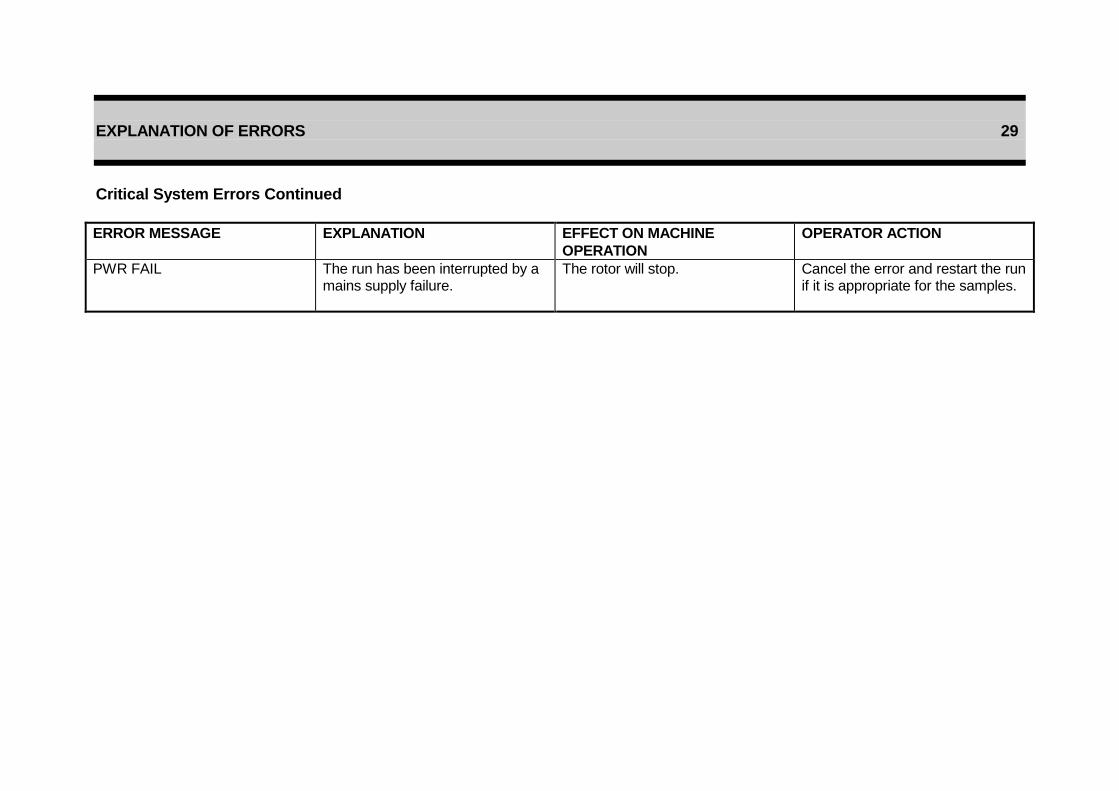
EXPLANATION OF ERRORS 29
Critical System Errors Continued
ERROR MESSAGE
EXPLANATION EFFECT ON MACHINE
OPERATION
OPERATOR ACTION
PWR FAIL The run has been interrupted by a mains supply failure.
The rotor will stop. Cancel the error and restart the run if it is appropriate for the samples.
EXPLANATION OF ERRORS 30
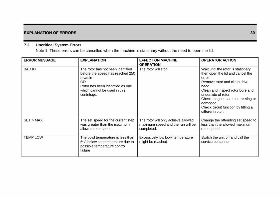
7.2 Uncritical System Errors
Note 1: These errors can be cancelled when the machine is stationary without the need to open the lid.
ERROR MESSAGE EXPLANATION EFFECT ON MACHINE
OPERATION
OPERATOR ACTION
BAD ID The rotor has not been identified before the speed has reached 250 rev/min OR Rotor has been identified as one which cannot be used in this centrifuge.
The rotor will stop Wait until the rotor is stationary then open the lid and cancel the error Remove rotor and clean drive head. Clean and inspect rotor bore and underside of rotor. Check magnets are not missing or damaged. Check circuit function by fitting a different rotor.
SET > MAX The set speed for the current step was greater than the maximum allowed rotor speed.
The rotor will only achieve allowed maximum speed and the run will be completed.
Change the offending set speed to less than the allowed maximum rotor speed.
TEMP LOW The bowl temperature is less than
6C below set temperature due to possible temperature control failure
Excessively low bowl temperature might be reached
Switch the unit off and call the service personnel

EXPLANATION OF ERRORS 31
Uncritical System Errors Continued
ERROR MESSAGE EXPLANATION EFFECT ON MACHINE
OPERATION
OPERATOR ACTION
TEMP HI The bowl temperature is more than
6C above set temperature due to refrigeration system failure.
Excessively high bowl temperature will occur if the rotor is running.
Switch the unit off and call the service personnel.
OVER 45 The bowl temperature has
exceeded 45, due to refrigeration system failure.
Machine will come to a stop.
Switch the unit off and call the service personnel.
IMB HIGH This only occurs when the machine is stationary and means the automatic imbalance test circuit has detected a fault with the imbalance detector. It can also occur if the rotor is knocked accidentally or there is a mains fluctuation.
Cancel the alarm. If the alarm persists call the service personnel.
IMB LOW This only occurs when the rotor is stationary and means the automatic imbalance test circuit has detected a fault with the imbalance detector. It can also occur if the rotor is knocked accidentally or there is an excessive mains fluctuation.
Cancel the alarm. If the alarm persists call the service personnel.

EXPLANATION OF ERRORS 32
Uncritical System Errors Continued
ERROR MESSAGE EXPLANATION EFFECT ON MACHINE
OPERATION
OPERATOR ACTION
BAD MEM The new data just entered has not been saved correctly in the controllers permanent memory.
Saved data may be corrupted. Cancel the error and try again. If the error persists call the service personnel.
BAD RCF The set RCF value is greater than the max. allowed RCF.
The motor will not start. Enter a smaller value for the set RCF.
HOTMOTOR The drive motor windings have overheated. The motor thermal cut-out has triggered.
The rotor will stop. Check the air inlet and outlet for blockages, if none are found call the service personnel.

ROTORS 33
8. ROTORS
8.1 Installation of Rotor
Before fitting a rotor to the centrifuge ensure that the drive head is clean. Check that the rotor is clean and pay particular attention to the pivot pins of swing-out rotors and the pockets in angle rotors. Locate the rotor on the drive shaft and ensuring that the correct spindle nut for the rotor in use is employed tighten nut using the spanner provided.
8.2 Removal of Rotor
Open the centrifuge lid to gain access, then set the power switch to OFF. Lift out all rotor accessories, e.g. buckets. Remove the spindle nut and grip the rotor. Gently ease the rotor upwards clear of the spindle. Note: Do not attempt to loosen the rotor by tapping on the drive head.
8.3 Loading the Rotor
Buckets, cups and trunnions are supplied as matched, balanced assemblies. It is important that all components should be stored and used together. The rotor must always be used with a full compliment of buckets, but it is not necessary for all buckets to be loaded, provided that the loads are placed symmetrically around the rotor.
When using the angle rotors ensure all the pockets are clean before fitting the buckets. When using the swing out rotor ensure that the buckets swing freely about their pivots.
If datum marks exist on the windshielded lids, ensure that these marks are aligned with the corresponding datum on the windshield body or rotor hub.
DO NOT RUN WINDSHIELDED ROTORS WITHOUT THEIR COVERS IN PLACE. FAILURE TO COMPLY WITH THIS REQUIREMENT COULD RESULT IN SERIOUS DAMAGE TO THE CENTRIFUGE DRIVE.
CARE MUST BE TAKEN TO PREVENT DISTORTION OF WINDSHIELDED ROTORS. LIFT THEM BY GRASPING THE ARMS OF ROTOR SPIDER AND NOT BY THE WINDSHIELD.
If using a swing-out rotor, check that all cups/buckets are correctly located on their pivot pins by ensuring that they swing freely. Biologically hazardous material should only be centrifuged in sealed buckets or cups.
ROTORS 34
8.4 Balancing the rotor
The loads should be reasonably balanced, which in most cases means equalising the liquid levels by eye. In the swing out rotor do not exceed 5 grams between loads when fully or partially loaded. When loading trunnion carriers the following procedure should be followed : 1) Weight group the buckets to within 5g. 2) Weight group the trunnion block and buckets as an assembly to within 5g.
FAILURE TO LOAD THE ROTOR CAREFULLY WILL TRIP THE OUT-OF-
BALANCE SENSOR, CAUSING THE CENTRIFUGE TO STOP.
In this case the display will show “M/C has imbalanced”. An unbalanced rotor will make the centrifuge noisy in operation.
8.5 Critical Speeds
Like all centrifuges the MISTRAL 3000i has a critical speed associated with each rotor. It is therefore recommended that continuous running between 400 - 700 rev/min is avoided.
8.6 Rotor Speed
Maximum speeds of rotors (see tables on following pages) are calculated on the basis of tubes filled with a sample of specific gravity 1.2. If liquids of higher specific gravity are used, the maximum speed of the rotor must be reduced according to formula:
M = 12 2.
Srev/min
Where M = New maximum speed N = Maximum rotor speed at 1.2 specific gravity S = Specific gravity of sample

ROTOR & ACCESSORY TABLES 35
9. ROTOR AND ACCESSORY TABLES
The following pages contain tables listing the rotors and accessories which are available for use with your Mistral 3000i centrifuge. The centrifuge complies with the requirements of BS 4402 only when fitted with one of the rotors show in these tables.
Mixed loads may be carried, providing that the two opposite buckets are carrying the same type of load.

ROTOR AND ACCESSORY TABLES 36
9.1 Table 1 Swing-out rotors
ROTOR CUP ADAPTOR ROTOR MAX. SPEED MAX. RCF x g TUBE SIZES
Packed sets of 4 Packed sets of 4 CAPACITY Dia (mm) Ht (mm)
inc.cap
4-place windhshielded swing-out 43124-708
Bucket assy 750 ml 43551.123 Bottle with cap 750 ml 43551-124 Blood bag liners 43551-126
43155-135 (red) 43155-134 (green) 43155-133 (orange) 43155-132 (blue) 43155-136 (yellow)
20 x 50 ml 76 x 20 ml 112 x 13 mm dia 148 x 12 mm dia 28 x 1 oz 4 x 750 ml
3660 3660 3660 3660 3660
3660
3660
2958 2898 2823 2823 2823
3003
3003
32.0 17 13 12 28.5
120 115 110 110 110
4-place swing-out 43124-129
Bucket assy 750 ml 43551-123 Blood bag liners 4355-126 Bottle with cap 750 ml 4355-124 Micro-titre carrier 41159-190
43155-132 (blue) 43155-133 (orange) 43155-134 (green) 43155-135 (red) 43155-136 (yellow)
148 x 12 mm dia 112 x 13 mm dia 76 x 20 ml 20 x 50 ml 28 x 1 oz 4 x 750 ml 4 x carrier (max. 3 trays per carrier)
2500 2500 2500 2500 2500
2500
2500
as indicated on carrier
1317 1317 1352 1380 1317
1401
1401
1000*
12 13 17 32.0 28.5 *Subject to capability of trays used
110 110 115 120 10

ROTOR AND ACCESSORY TABLES 37
Table 1 Swing-out rotors continued
ROTOR CUP ADAPTOR ROTOR MAX. SPEED MAX. RCF x g TUBE SIZES
Packed sets of 4 Packed sets of 4 CAPACITY Dia (mm) Ht (mm)
inc.cap
8-place swing-out 43122.105
Sealed cup 200 ml 43551-121
34159-302 (brown) 34159-301 (yellow) 34159-304 (green) 34159-303 (grey) 34159-305 (orange) 34159-306 (blue)
8 x 100ml 8 x 50 ml (DHSS bottle)
56 x 15 ml 32 x 10 ml (DHSS) 72 x 13 mm dia 96 x 12 mm dia
3200 3200 3200 3200 3200 3200
2375 2375 2375 2358 2370 2375
39.5 29 17 16.5 13 12
113 113 110 105 110 110
Bottle with cap 200 ml 43551-103 (each)
8 x 200 ml
3200
2301
(open kit) 2393
(sealed kit)
57
116

ROTOR AND ACCESSORY TABLES 38
9.2 Table 2 Angle rotors
ROTOR CUP ADAPTOR ROTOR MAX. SPEED MAX. RCF x g TUBE SIZES
Packed sets of 4 Packed sets of 4 CAPACITY Dia (mm) Ht (mm)
inc.cap
6 place universal angle 43117-605
34411-912 34411-912 34411-912 34411-912 34411-912
34142-105 34144-308 34151-302 34144-307 34153-302
6 x 100 ml 6 x 50 ml 12 x 15 ml 6 x 15 ml 30 x 7 ml
6000 6000 6000 6000 6000
5524 5108 5524 5524 5311
42 29 17 17 13
125 120 118 118 118
16 place universal angle 43114-609
34144-307
16 x 50 ml 16 x 15 ml
6000 6000
5920 5720
20 (plastic) 17.5
110 100
24 place universal angle 43114-608
24 x 15 ml
6000
6030
17
108

MAINTENANCE 39
10. MAINTENANCE
This section describes the basic maintenance procedures, in particular, the methods and materials used for cleaning the centrifuge, rotors and accessories. It is recommended that a regular inspection of the centrifuge is made after 1000 hours of operation or at least once per year, whichever is the sooner. This should include all rotors and accessories. Electricity at Work Regulations (1989). Portable Appliance Testing (PAT) - Where applicable this centrifuge should be inspected and tested regularly in accordance with these regulations and the appropriate records kept.
FUSE REPLACEMENT SHOULD ONLY BE CARRIED OUT BY A QUALIFIED
ELECTRICIAN. For Warranty Service and Maintenance please see the details given at the front of this manual.
10.1 Cleaning
To maintain a good appearance and to prevent dirt build-up, the casing and the inside of the bowl should be cleaned regularly using a soft cloth dampened with a neutral detergent and warm water. The keypad and display may also be cleaned in this manner, but should be wiped dry immediately.
If corrosive materials are used in the centrifuge, it is especially important to clean out the centrifuge bowl thoroughly. If a major spillage occurs in the bowl, the excess liquid should be mopped out and the bowl then cleaned using a suitable cleaning agent.
10.2 Disinfecting
To disinfect the centrifuge the following cleaning fluids may be used
TERMINEX 2 (Available from Arrow Chemicals Ltd)
VIRKON (available from Antec International) These cleaning agents if used as instructed by the manufacturer should not be harmful to the centrifuge or the accessories supplied for use with it.
WARNING
SOLVENTS OR GRITTY CLEANERS SHOULD NEVER BE USED
EXCESSIVE USE OF WATER SHOULD BE AVOIDED

MAINTENANCE 40
10.3 Drive shaft
The drive shaft should be cleaned periodically with a solvent to remove excessive grease. When clean, re-lubricate the shaft lightly with petroleum jelly.
10.4 Rotors and buckets.
The rotors and accessories should be handled with care to avoid damage. Prior to storage, all components should be protected against corrosion using MSE Rotor Spray (Cat No. 17341-1512) which is an anti-corrosion and de-waterizing agent. The rotors, metal buckets, cups, carriers and adaptors should all be washed after use with a neutral detergent and afterwards dried and stored in a dry place. Buckets and cups should be stored inverted. The pivot areas of the swing-out rotors, i.e. the pivot pins on the rotor and the slots on the buckets, should be lubricated periodically with Molykote 321 R Anti-Friction coating (a spray can is the most convenient application method).
10.5 O-Rings.
Ensure that the O-Rings fitted to the sealing caps are lightly coated with silicone grease. Check the O-Rings regularly for cuts and abrasions, replacing as necessary but at least once a year.
10.6 Sterilisation.
All of the rotors, buckets and sealing caps (with O-Rings removed) may be sterilised by autoclaving at 121°C for 22 minutes. The plastic adaptors may be
autoclaved at 121C for 10 minutes.
If the means available for disinfection of certain microbiological agents are in-adequate, the safety officer should be consulted and appropriate steps taken.
10.7 Lid seal.
Lightly coat the lid seal with French chalk occasionally and in particular after cleaning.
10.8 Detection of Corrosion
Simple corrosion can usually be detected by eye. It appears in the form of pitting, or white fluffy deposits on the surface of the aluminium rotor or buckets. Following the maintenance procedure outlined should prolong the life of your centrifuge and accessories.

SERVICE INSTRUCTIONS 41
11. SERVICE INSTRUCTIONS
Sanyo Gallenkamp plc are committed to giving our customers the best possible service. If your centrifuge should require service at any time please follow these procedures: -
All countries except UK, USA and CANADA - Contact your local Sanyo Gallenkamp distributor, details can be found on our website: www.sanyogallenkamp.com.
UK only For all technical and service enquires contact: - SANYO GALLENKAMP PLC Monarch Way Belton Park Loughborough Leicester LE11 5XG Telephone +44 (0) 1509 265265 Fax +44 (0) 1509 269770 E-mail: [email protected]
USA only For all technical and service enquiries contact: - SANYO Sales & Supply Company SANYO Scientific 900 North Arlington Heights Road Suite 310 Itasca Illinois 60143-2844 Telephone: (800) 858-8442 (Toll Free) Fax: (630) 775-9580
CANADA only For all technical and service enquires contact: - SANYO Scientific North America Telephone: (800) 261-7734 (Toll Free) Fax: (416) 889-3047
1. Contact the repairs centre - have the model, serial number, and date of purchase and fault description available.
2. You will be given a return goods authorisation number and directions for shipping.
3. Remove all rotors, buckets and adapters. Do not ship these items - only the centrifuge.
4. Thoroughly clean and disinfect the centrifuge.
5. Fill out the attached service request form and place inside the centrifuge.
6. Pack in a protective box (preferably that in which the centrifuge was originally supplied).
7. ‘SANYO Sales and Supply Company’ or ‘SANYO Scientific North America’ will specify the carrier to be used and will give details of how the freight is to be charged.

MISTRAL 3000i SERVICE REQUEST FORM Should it become necessary to have your MSE centrifuge repaired. Please take a few moments to fill out this form which will help us to ensure you receive the best and fastest service possible. Serial number :- (on plate at back of unit)
...........................................................................
Date purchased :- ...........................................................................
Where purchased :- ...........................................................................
Brief description of fault :- ........................................................................... ........................................................................... ...........................................................................
Date fault first occurred :- ...........................................................................
Date repair centre contacted :- ...........................................................................
Authorisation number :- ...........................................................................
Condition of centrifuge :- ...........................................................................
Has it been disinfected? Yes / No
Disinfectant used :- ...........................................................................
Contact name :- ...........................................................................
Address :- ........................................................................... ........................................................................... ...........................................................................
Telephone Number :- ...........................................................................
Signature :-
...........................................................................


SANYO Gallenkamp PLC
Monarch Way, Belton Park, Loughborough, Leics, LE11 5XG, UK. Tel: +44 (01509) 265265 Fax: +44 (01509) 269770 E-mail: [email protected] Web: www.sanyogallenkamp.com