instruction manual - cogeflu
TRANSCRIPT

ESE00691EN1 2008-10
Unique Single Seat Valve Y-body
Instruction Manual
TD 461-803

2

Alfa Laval Company Name
Bjarne Søndergaard
Declaration of Conformity
The designating company
Designation
is in conformity with the following directive:
- Machinery Directive 98/37/EEC
- Pressure Equipment Directive 97/23/EC category 1 and subjected to assessment procedure Module A.
hereby declare that
Denomination Type Year
Address
Phone No.
NameTitle
Company Signature
Manager, Product Centres, Compact Heat Exchangers & Fluid Handling
Alfa Laval Kolding
Albuen 31, DK-6000 Kolding, Denmark
+45 79 32 22 00
3
Unique Single Seat Valve Y-body 2008

4

The information contained herein is correct at the time of issue but may be subject to change without prior notice.
5
1. Safety ..................................................................................................... 61.1 Important information ........................................................................ 61.2 Warning signs ................................................................................... 61.3 Safety precautions ............................................................................ 7
2. Installation ............................................................................................. 82.1. Unpacking/Delivery .......................................................................... 82.2. General installation ........................................................................... 92.3. Welding.......................................................................................... 10
3. Operation ............................................................................................. 113.1 Operation ........................................................................................ 113.2 Trouble shooting ............................................................................. 133.3 Recommended cleaning ................................................................. 14
4. Maintenance ........................................................................................ 164.1 General maintenance ...................................................................... 164.2 Dismantling of valve ........................................................................ 184.3 Plug seal replacement ..................................................................... 194.4 Assembly of valve ........................................................................... 194.5 Actuator bushing replacement ........................................................ 19
5. Technical data ...................................................................................... 205.1 Technical data ................................................................................. 20
6. Parts List and Service Kits ................................................................. 216.1 Unique Single Seat Valve - Y-body .................................................. 21
Table of contents

6
Unsafe practices and other important information are emphasized in this manual.Warnings are emphasized by means of special signs.
Always read the manual before using the valve!
WARNING!Indicates that special procedures must be followed to avoid severe personal injury.
CAUTION!Indicates that special procedures must be followed to avoid damage to the valve.
NOTE!Indicates important information to simplify or clarify practices.
1.1 Important information1.2 Warning signs
1. Safety
General warning:
Caustic agents:

7
Installation- Always read the technical data thoroughly (see chapter 5).- Always release compressed air after use.- Never touch the moving parts if the actuator is supplied with compressed air.- Never touch the valve or the pipelines when processing hot liquids or when sterilizing.- Never dismantle the valve with valve and pipelines under pressure.- Never dismantle the valve when it is hot.
Operation- Never dismantle the valve with valve and pipelines under pressure.- Never dismantle the valve when it is hot.- Always read the technical data thoroughly (see chapter 5).- Always release compressed air after use.- Never touch the valve or the pipelines when processing hot liquids or when sterilizing.- Never touch the moving parts if the actuator is supplied with compressed air.- Always rinse well with clean water after the cleaning.
Always handle lye and acid with great care.
Maintenance- Always read the technical data thoroughly (see chapter 5).- Always release compressed air after use.- Never service the valve when it is hot.- Never service the valve with valve and pipelines under pressure.- Never stick your fingers through the valve ports if the actuator is supplied with compressed air.- Never touch the moving parts if the actuator is supplied with compressed air.
All warnings in the manual are summarized on this page.Pay special attention to the instructions below so that severe personal injury and/or damage to the valve are avoided.
1. Safety 1.3 Safety precautions

8
TD 461-775
2. Installation
The instruction manual is part of the delivery. Study the instructions carefully.The items refer to parts list and service kits section.The valve is assembled before delivery.
Step 1CAUTION!Alfa Laval cannot be held responsible for incorrect unpacking.
Check the delivery for:1. Complete valve (see steps 2).2. Delivery note.3. Instruction Manual.
2.1. Unpacking/Delivery
Step 2Complete actuator.Bonnet (20).Upper clamp (19).Valve plug (36).Valve body (22)Lower clamp (61).
Step 3Remove possible packing materials from the valve/valve parts.Inspect the valve/valve parts for visible transport damages. Avoid damaging the valve/valve parts.
9
TD 461-760
TD 461-761
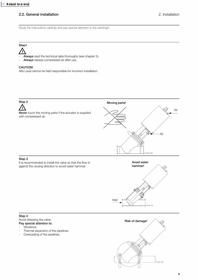
2. Installation2.2. General installation
Study the instructions carefully and pay special attention to the warnings!
Step1
- Always read the technical data thoroughly (see chapter 5).- Always release compressed air after use.
CAUTION!Alfa Laval cannot be held responsible for incorrect installation.
Risk of damage!
Inlet
Avoid waterhammer!
Step 2
Never touch the moving parts if the actuator is supplied with compressed air.
Step 3It is recommended to install the valve so that the flow is against the closing direction to avoid water hammer.
Step 4Avoid stressing the valve.Pay special attention to:- Vibrations.- Thermal expansion of the pipelines.- Overloading of the pipelines.
Air
Air
Moving parts!
TD 461-762

10
Step 1
Study the instructions carefully. The items refer to the parts list and service kits section.
Step 2Assemble the valve in accordance with the steps in section 4.4.Pay special attention to the warnings!
Step 3Pre-use check:1. Supply compressed air to the actuator.2. Open and close the valve several times to ensure that it operates smoothly.Pay special attention to the warnings!
2. Installation 2.3. Welding
Open/close!
Air
Air
Valve size Min. A (mm)
DN50/51 mm 478 DN65/63.5 mm 490 DN80/76.1 mm 564 DN100/101.6 mm 605
(incl
. top
uni
t)
TD 461-763
A
TD 461-764
TD 461-765

11
3.1 Operation 3. Operation
Study the instructions carefully and pay special attention to the warnings!Ensure that the valve operates smoothly. The items refer to the parts list and service kits section.
Step 1
- Always read the technical data thoroughly (see chapter 5).- Always release compressed air after use.
CAUTION!Alfa Laval cannot be held responsible for incorrect operation.
Step 2
Never touch the valve or the pipelines when processing hot liquids or when sterilizing.
Step 3
Never touch the moving parts if the actuator is supplied with compressed air.
Step 4Lubrication of valves:1. Ensure smooth movement between lip seal (25) and plug stem (36).2. Lubricate with Klüber Paraliq GTE 703 if necessary. (see section 4.1)
Air
Air
Burning danger!
Moving parts!TD
461
-767
3625
TD 461-766
TD 461-760

12
3.1 Operation3. Operation
Step 5Lubrication of actuator1. Ensure smooth movement of the actuator (the actuator is lubricated before delivery).2. Lubricate with Molykote Longterm 2 plus if necessary.
TD 461-768
13
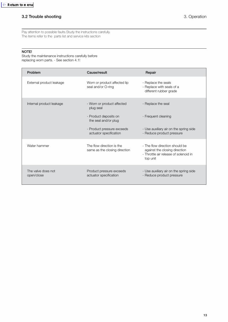
3. Operation3.2 Trouble shooting
Pay attention to possible faults.Study the instructions carefully. The items refer to the parts list and service kits section
NOTE!Study the maintenance instructions carefully before replacing worn parts. - See section 4.1!
External product leakage Worn or product affected lip - Replace the seals seal and/or O-ring - Replace with seals of a different rubber grade
Internal product leakage - Worn or product affected - Replace the seal plug seal - Product deposits on - Frequent cleaning the seal and/or plug - Product pressure exceeds - Use auxiliary air on the spring side actuator specification - Reduce product pressure
Water hammer The flow direction is the - The flow direction should be same as the closing direction against the closing direction - Throttle air release of solenoid in top unit
The valve does not Product pressure exceeds - Use auxiliary air on the spring side open/close actuator specification - Reduce product pressure
Problem Cause/result Repair
14
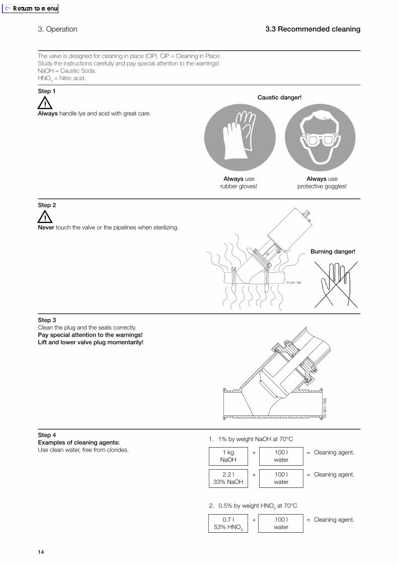
3. Operation 3.3 Recommended cleaning
The valve is designed for cleaning in place (CIP). CIP = Cleaning In Place.Study the instructions carefully and pay special attention to the warnings!NaOH = Caustic Soda.HNO
3 = Nitric acid.
Step 1
Always handle lye and acid with great care.
Step 2
Never touch the valve or the pipelines when sterilizing.
Step 3Clean the plug and the seals correctly. Pay special attention to the warnings!Lift and lower valve plug momentarily!
Step 4Examples of cleaning agents:Use clean water, free from clorides.
Caustic danger!
Always use Always use rubber gloves! protective goggles!
1 kg + 100 l = Cleaning agent. NaOH water
2.2 l + 100 l = Cleaning agent. 33% NaOH water
0.7 l + 100 l = Cleaning agent. 53% HNO3 water
4
1. 1% by weight NaOH at 70°C
2. 0.5% by weight HNO3 at 70°C
Burning danger!
TD 4
61-7
69
TD 461-766

15
Step 5
1. Avoid excessive concentration of the cleaning agent2. Adjust the cleaning flow to the process3. Always rinse well with clean water after the cleaning.
Step 6NOTE!The cleaning agents must be stored/disposed of in accordance with current rules/directives.
3. Operation3.3 Recommended cleaning
Always rinse!
Clean water Cleaning agents
16
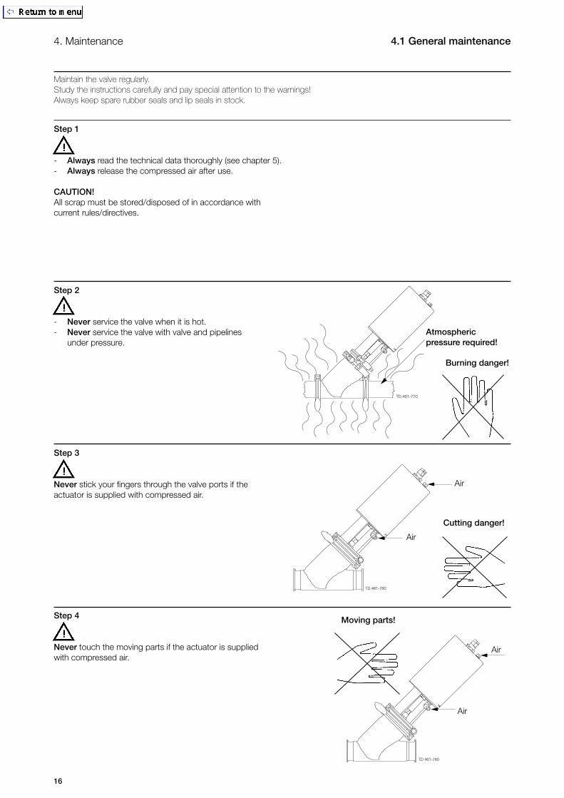
4.1 General maintenance4. Maintenance
Maintain the valve regularly.Study the instructions carefully and pay special attention to the warnings!Always keep spare rubber seals and lip seals in stock.
Step 1
- Always read the technical data thoroughly (see chapter 5).- Always release the compressed air after use.
CAUTION!All scrap must be stored/disposed of in accordance with current rules/directives.
Step 2
- Never service the valve when it is hot.- Never service the valve with valve and pipelines under pressure.
Step 3
Never stick your fingers through the valve ports if the actuator is supplied with compressed air.
Step 4
Never touch the moving parts if the actuator is supplied with compressed air.
Atmospheric pressure required!
Air
Burning danger!
Cutting danger!
Air
Air
Air
Moving parts!
TD 461-770
TD 461-760
TD 461-760

17
4. Maintenance4.1 General maintenance
Maintain the valve regularly.Study the instructions carefully.Always keep spare rubber seals and lip seals stock.Check the valve for smooth operation after service.
Pre-use check:1. Supply compressed air to the actuator.2. Open and close the valve several times to ensure that it operates smoothly. Pay special attention to the warnings!
Air
Open/close!
Air
Recommended spare partsService kits (see chapter 6)
Below are some guidelines for maintenance and lubrication intervals. Please note that the guidelines are for normal working conditions in one shift.
Product wetted Actuator seals bushings complete
Preventive Replace after Replace after maintenance 12 months depending 5 years depending on working conditions on working conditions
Maintenance after Replace at the Replace when leakage (leakage end of the day possible normally starts slowly)
Planned - Regular inspection - Regular inspection maintenance for leakage and for leakage and smooth operation smooth operation - Keep a record of - Keep a record of the valve the actuator - Use the statistics for - Use the statistics for planning of inspections planning of inspections Replace after leakage Replace after leakage Lubrication Before fitting Before fitting Klüber Paraliq GTE 703 Molykote Longterm 2 plus or similar USDA H1 approved oil/grease
TD 461-765

18
4. Maintenance 4.2 Dismantling of valve
Study the instructions carefully. The items refer to the parts list and service kits section. Handle scrap correctly.NC = Normally closed.NO = Normally open.A/A = Air/air activated.
Step 11. Supply compressed air to the actuator (only NC).2. Loosen and remove lower clamp.3. Release compressed air (only NC).4. Lift away the actuator.5. Remove body gasket.6. Unscrew and remove valve plug.7. Loosen and remove upper clamp.8. Remove O-ring, lip seal and bushing in bonnet. (Use bushing tool and rubber mallet. See drawing).Pay special attention to the warnings!
Note! For plug seal replacement please see section 4.3.
TD 461-771
TD 461-772
Note!Be careful not to damage the bushing.
19
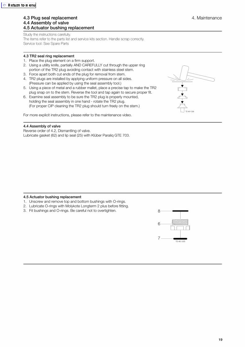
4.3 Plug seal replacement 4.4 Assembly of valve4.5 Actuator bushing replacement
4. Maintenance
4.4 Assembly of valveReverse order of 4.2, Dismantling of valve.Lubricate gasket (62) and lip seal (25) with Klüber Paraliq GTE 703.
4.3 TR2 seal ring replacement1. Place the plug element on a firm support.2. Using a utility knife, partially AND CAREFULLY cut through the upper ring portion of the TR2 plug avoiding contact with stainless steel stem.3. Force apart both cut ends of the plug for removal from stem.4. TR2 plugs are installed by applying uniform pressure on all sides. (Pressure can be applied by using the seal assembly tool.)5. Using a piece of metal and a rubber mallet, place a precise tap to make the TR2 plug snap on to the stem. Reverse the tool and tap again to secure proper fit.6. Examine seal assembly to be sure the TR2 plug is properly mounted, holding the seal assembly in one hand - rotate the TR2 plug. (For proper CIP cleaning the TR2 plug should turn freely on the stem.)
For more explicit instructions, please refer to the maintenance video.
4.5 Actuator bushing replacement1. Unscrew and remove top and bottom bushings with O-rings.2. Lubricate O-rings with Molykote Longterm 2 plus before fitting.3. Fit bushings and O-rings. Be careful not to overtighten. 8
6
7
Study the instructions carefully. The items refer to the parts list and service kits section. Handle scrap correctly.Service tool: See Spare Parts

20
5. Technical data5.1 Technical data
It is important to observe the technical data during installa tion, operation and maintenance.Inform the personnel about the technical data.
Data - valve/actuator
Max. product pressure ....................................................... 1000 kPa (10 bar)Min. product pressure ........................................................ Full vacuum (depending on product specifications)Temperature range ............................................................ -10o C to + 140o C (standard EPDM seal)Air pressure, actuator ........................................................ 500 to 700 kPa) (5 to 7 bar)
Materials - valve/actuator
Product wetted steel parts ................................................. 1.4404 (316L) (internal Ra < 0.8 µm)Other steel parts ................................................................ 1.4301 (304)Plug seal ............................................................................ PTFE (TR2) Other product wetted seals ............................................... EPDM (standard)Optional product wetted seals ........................................... HNBR/NBR and FPMOther seals ........................................................................ NBR

21
6. Parts List and Service Kits 6.1 Unique Single Seat Valve - Y-body
For parts lists please see section 6.1. The drawings include all items.
TD 461-774
Normally Closed (NC)

22
6. Parts List and Service Kits6.1 Unique Single Seat Valve - Y-body
For parts lists please see section 6.1. The drawings include all items.
TD 461-812
5
24

23
The parts list includes all items.
Service Kits/Product wetted parts
Denomination TR2
Actuator .................... 9611-92-6500
DN40/38 mm
EPDM ........................ 9611-92-6815HNBR ........................ 9611-92-6819FPM .......................... 9611-92-6823
DN50/51 mm
EPDM ........................ 9611-92-6816HNBR ........................ 9611-92-6820FPM .......................... 9611-92-6824
DN65/63.5 mm
EPDM ........................ 9611-92-6817HNBR ........................ 9611-92-6821FPM .......................... 9611-92-6825
DN100/101.6 mm
EPDM ........................ 9611-92-6818HNBR ........................ 9611-92-6822FPM .......................... 9611-92-6826
Parts List
Pos. Qty. Denomination
Actuator, complete5 1 Adapter6 l 2 Bushing7 l 2 O-ring8 l 2 O-ring9 1 Plug12 1(2) Air fitting19 1 Clamp20 1 Bonnet22 1 Valve body 24 1 Bushing25 ∆ 1 Lip seal36 1 Plug, complete 36.1 1 Plug36.2 ∆ 1 Plug seal, PTFE 61 1 Clamp body62 ∆ 1 Gasket
l: Service kits - Actuator∆: Service kits - EPDM∆: Service kits - HNBR/NBR∆: Service kits - FPM
6. Parts list and Service Kits 6.1 Unique Single Seat Valve - Y-body

How to contact Alfa LavalContact details for all countries arecontinually updated on our website.Please visit www.alfalaval.com toaccess the information direct.