instruction m anual - sensoray · sensoray believes that the information in this manual is...
TRANSCRIPT
Support: [email protected] www.sensoray.com
Sensoray Model 322
PC104+ Video Graphics Adapter Manual Revision B
June 1, 2001
INSTRUCTION MANUAL

This page is intentionally blank
Page 3 Sensoray Model 322 Instruction Manual
Table of Contents 1. SPECIAL HANDLING INSTRUCTIONS ............................................................................................................... 7
2. INTRODUCTION ..................................................................................................................................................... 8
2.1 GENERAL DESCRIPTION ........................................................................................................................................ 8 2.2 FEATURES ........................................................................................................................................................... 8
2.2.1 VGA Core ....................................................................................................................................................... 8 2.2.2 Video Memory System ..................................................................................................................................... 8 2.2.3 CRT Interface ................................................................................................................................................. 8 2.2.4 TV Output ....................................................................................................................................................... 8 2.2.5 LCD Controller............................................................................................................................................... 8 2.2.6 Graphics and Video Engines ........................................................................................................................... 8
3. SPECIFICATIONS ................................................................................................................................................... 9
3.1 BUS SPECIFICATIONS............................................................................................................................................ 9 3.2 VIDEO MODES ...................................................................................................................................................... 9
3.2.1 Standard IBM Compatible VGA Modes ........................................................................................................... 9 3.2.2 Vesa Super VGA Modes................................................................................................................................. 10 3.2.3 Extended Modes............................................................................................................................................ 10 3.2.4 NTSC and PAL TV Modes ............................................................................................................................. 10 3.2.5 Low Resolution Modes .................................................................................................................................. 10 3.2.6 640x480 Extended Modes.............................................................................................................................. 11 3.2.7 800x600 Resolution Modes............................................................................................................................ 11 3.2.8 1024x768 Extended Resolution Modes........................................................................................................... 12 3.2.9 1280x1024 Resolution Modes for CRT only ................................................................................................... 12 3.2.10 1280x1024 Extended Modes for LCD only................................................................................................. 12 3.2.11 1280x1024 Extended Modes...................................................................................................................... 12
3.3 DRIVER SUPPORT ............................................................................................................................................... 13 3.4 BOARD SIZE ...................................................................................................................................................... 13 3.5 POWER SPECIFICATIONS ..................................................................................................................................... 13 3.6 OPERATING ENVIRONMENT ................................................................................................................................ 13 3.7 POWER ON CONFIGURATION .............................................................................................................................. 13 3.8 SUPPORTED LCD FLAT PANELS .......................................................................................................................... 13
3.8.1 Supported XGA Panels 1024x768 .................................................................................................................. 13 3.8.2 Supported SVGA Panels 800x600 .................................................................................................................. 14 3.8.3 Supported VGA Panels 640x480.................................................................................................................... 14
3.9 CONNECTOR INFORMATION ................................................................................................................................ 15 3.9.1 CRT VGA Connector (J6).............................................................................................................................. 15 3.9.2 Composite Video connector (J3).................................................................................................................... 15 3.9.3 S-Video connector (J1).................................................................................................................................. 15 3.9.4 Mixed Signal Header (J2).............................................................................................................................. 15 3.9.5 LCD flat panel connector (J4) ....................................................................................................................... 15
4. INSTALLATION .................................................................................................................................................... 15
4.1 INTRODUCTION .................................................................................................................................................. 15 4.2 PCI SLOT AND INTERRUPT JUMPER CONFIGURATION........................................................................................... 15
4.2.1 PCI Slot Selection ......................................................................................................................................... 15 4.2.2 PCI Interrupt Selection ................................................................................................................................. 16
4.3 CRT INTERFACING............................................................................................................................................. 16 4.4 TV INTERFACING............................................................................................................................................... 16 4.5 LCD INTERFACING ............................................................................................................................................ 17
4.5.1 LCD Type Selection ...................................................................................................................................... 17 4.5.2 LCD Connector and Pinouts.......................................................................................................................... 17 4.5.3 LCD Power Sequencing ................................................................................................................................ 18
4.6 DRIVERS............................................................................................................................................................ 18
5. BIOS ........................................................................................................................................................................ 19

Page 4 Sensoray Model 322 Instruction Manual
5.1 OVERVIEW......................................................................................................................................................... 19 5.2 BIOS SIZE AND FORMAT .................................................................................................................................... 19 5.3 BIOS FEATURES ................................................................................................................................................. 19
5.3.1 Flat Panel Expansion .................................................................................................................................... 19 5.3.2 NTSC/PAL TV Support .................................................................................................................................. 19 5.3.3 Display Switching.......................................................................................................................................... 19
5.4 STANDARD IBM VGA COMPATIBLE BIOS FUNCTIONS....................................................................................... 20 5.5 EXTENDED BIOS FUNCTION CALLS .................................................................................................................... 22
5.5.1 Get Current VGA Information - 5F00h .......................................................................................................... 22 5.5.2 Set Panel On - 5F05h .................................................................................................................................... 23 5.5.3 Set Panel Off - 5F06h.................................................................................................................................... 23 5.5.4 Monitor Detection - 5F0Eh............................................................................................................................ 23 5.5.5 PopUp Icon Control - 5F10h......................................................................................................................... 23 5.5.6 PopUp Icon Size - 5F10h............................................................................................................................... 24 5.5.7 PopUp Icon Location - 5F10h ....................................................................................................................... 24 5.5.8 PopUp Icon Color1 - 5F10h .......................................................................................................................... 24 5.5.9 PopUp Icon Color2 - 5F10h .......................................................................................................................... 24 5.5.10 PopUp Icon Color3 - 5F10h...................................................................................................................... 25 5.5.11 PopUp Icon Bitmap - 5F10h...................................................................................................................... 25 5.5.12 Display Switching Status - 5F12h .............................................................................................................. 25 5.5.13 Switch Display to LCD - 5F13h................................................................................................................. 25 5.5.14 Switch Display to CRT - 5F14h ................................................................................................................. 26 5.5.15 Switch Display to Simul - 5F15h................................................................................................................ 26 5.5.16 Switch Display to CRT only - 5F16h.......................................................................................................... 26 5.5.17 Set Text Expansion/Graphics Expansion/Stretch - 5F19h ........................................................................... 27 5.5.18 Set Extended Memory - 5F20h................................................................................................................... 27 5.5.19 Switch from LCD to TV display - 5F21h .................................................................................................... 27 5.5.20 Switch from CRT to TV display - 5F22h..................................................................................................... 28 5.5.21 Switch from Simul to TV display - 5F23h................................................................................................... 28 5.5.22 Switch from TV to LCD display - 5F24h .................................................................................................... 28 5.5.23 Switch from TV to CRT display - 5F25h..................................................................................................... 28 5.5.24 Switch from TV to Simul display - 5F26h................................................................................................... 29
5.6 INT15 SYSTEM BIOS FUNCTION CALLS ............................................................................................................. 30 5.6.1 VGA POST Initialization - 7F00h .................................................................................................................. 30 5.6.2 Get Panel ID - 7F01h.................................................................................................................................... 30 5.6.3 Boot Display Device Override - 7F02h .......................................................................................................... 31 5.6.4 Do Expansion or Centering - 7F03h .............................................................................................................. 31 5.6.5 Normal Set Mode or Special Set Mode - 7F04h.............................................................................................. 31 5.6.6 Select TV Type - 7F05h ................................................................................................................................. 31 5.6.7 Get TV Support Status - 7F06h ...................................................................................................................... 31 5.6.8 Set sub-vendor and sub-system ID's - 7F07h .................................................................................................. 32 5.6.9 Select Text Expansion/Graphic Expansion/Stretch initial status - 7F08h ........................................................ 32 5.6.10 Get Dual Monitor Support Status - 7F09h ................................................................................................. 32 5.6.11 TV DAC Option - 7F0Ah ........................................................................................................................... 32 5.6.12 VGA POST Completion Signal - 7F0Fh..................................................................................................... 33
5.7 VESA BIOS FUNCTIONS.................................................................................................................................... 34 5.8 BIOS DATA AREA DESCRIPTION ........................................................................................................................ 38
APPENDIX A: MANUAL REVISION NOTES .......................................................................................................... 39
APPENDIX B: TECHNICAL SUPPORT ................................................................................................................... 39

Page 5 Sensoray Model 322 Instruction Manual
Tables
Table 1 Standard IBM Compatible VGA Modes................................................................................................................... 9 Table 2 VESA Super VGA Modes ..................................................................................................................................... 10 Table 3 Low Resolution Modes.......................................................................................................................................... 10 Table 4 640x480 Extended Modes...................................................................................................................................... 11 Table 5 800x600 Resolution Modes.................................................................................................................................... 11 Table 6 1024x768 Extended Resolution Modes .................................................................................................................. 12 Table 7 1280x1024 Resolution Modes for CRT only .......................................................................................................... 12 Table 8 1280x1024 Extended Modes for LCD only ............................................................................................................ 12 Table 9 1280x1024 Extended Modes.................................................................................................................................. 12 Table 10 Supported XGA Panels 1024x768........................................................................................................................ 13 Table 11 Supported SVGA Panels 800x600........................................................................................................................ 14 Table 12 Supported VGA Panels 640x480.......................................................................................................................... 14 Table 13 PCI Slot Selection................................................................................................................................................ 15 Table 14 PCI Interrupt ....................................................................................................................................................... 16 Table 15 CRT DB15 (J6) pinout......................................................................................................................................... 16 Table 16 Mixed Header (J2) pinout .................................................................................................................................... 16 Table 17 S-Video (J1) pinout ............................................................................................................................................. 16 Table 18 LCD Type Selection Jumpers............................................................................................................................... 17 Table 19 LCD connector (J4) ............................................................................................................................................. 17 Table 20 Standard IBM VGA Compatible BIOS Functions................................................................................................. 20 Table 21 Extended BIOS Function Calls ............................................................................................................................ 22 Table 22 INT15 System BIOS function calls ...................................................................................................................... 30 Table 23 Panel ID .............................................................................................................................................................. 30 Table 24 VESA BIOS Function Calls................................................................................................................................. 34 Table 25 BIOS Data Area Description................................................................................................................................ 38

Page 6 Sensoray Model 322 Instruction Manual
Limited Warranty
Sensoray Company, Incorporated (Sensoray) warrants the Model 322 hardware to be free from defects in material and workmanship and perform to applicable published Sensoray specifications for two years from the date of shipment to purchaser. Sensoray will, at its option, repair or replace equipment that proves to be defective during the warranty period. This warranty includes parts and labor. The warranty provided herein does not cover equipment subjected to abuse, misuse, accident, alteration, neglect, or unauthorized repair or installation. Sensoray shall have the right of final determination as to the existence and cause of defect. As for items repaired or replaced under warranty, the warranty shall continue in effect for the remainder of the original warranty period, or for ninety days following date of shipment by Sensoray of the repaired or replaced part, whichever period is longer. A Return Material Authorization (RMA) number must be obtained from the factory and clearly marked on the outside of the package before any equipment will be accepted for warranty work. Sensoray will pay the shipping costs of returning to the owner parts that are covered by warranty. Sensoray believes that the information in this manual is accurate. The document has been carefully reviewed for technical accuracy. In the event that technical or typographical errors exist, Sensoray reserves the right to make changes to subsequent editions of this document without prior notice to holders of this edition. The reader should consult Sensoray if errors are suspected. In no event shall Sensoray be liable for any damages arising out of or related to this document or the information contained in it. EXCEPT AS SPECIFIED HEREIN, SENSORAY MAKES NO WARRANTIES, EXPRESS OR IMPLIED, AND SPECIFICALLY DISCLAIMS ANY WARRANTY OF MERCHANTABILITY OR FITNESS FOR A PARTICULAR PURPOSE. CUSTOMER’S RIGHT TO RECOVER DAMAGES CAUSED BY FAULT OR NEGLIGENCE ON THE PART OF SENSORAY SHALL BE LIMITED TO THE AMOUNT THERETOFORE PAID BY THE CUSTOMER. SENSORAY WILL NOT BE LIABLE FOR DAMAGES RESULTING FROM LOSS OF DATA, PROFITS, USE OF PRODUCTS, OR INCIDENTAL OR CONSEQUENTIAL DAMAGES, EVEN IF ADVISED OF THE POSSIBILITY THEROF.
Page 7 Sensoray Model 322 Instruction Manual
1. Special Handling Instructions
The Model 322 circuit board contains CMOS circuitry that is sensitive to Electrostatic Discharge (ESD). Special care should be taken in handling, transporting, and installing the Model 322 to prevent ESD damage to the board. In particular: • Do not remove the circuit board from its protective anti-static bag until you are ready to configure the board for
installation. • Handle the circuit board only at grounded, ESD protected stations. • Remove power from the PCI system before installing or removing the circuit board.
Page 8 - Introduction - General description
Page 8 Sensoray Model 322 Instruction Manual
2. Introduction
2.1 General description The Sensoray Model 322 is a compact, rugged, and low cost PC104+ Video Graphics Adapter that combines the functionality of a high-powered desktop graphics adapter to provide a powerful graphics solution for embedded applications. The 322 is suitable for high bandwidth video and multimedia embedded applications taking full advantage of the PCI bus throughput, very wide video buffer memory, and multiple onboard video engines. Using the very latest in single chip video graphics controller, lower power consumption, enhanced reliability and ruggedness are characteristics of the 322. The 322 is compatible with any PC/104+ complaint CPU board such as the Sensoray Model 1101. Outputs for a CRT monitor (RGB), a LCD flat panel display (DSTN and TFT), and a TV (NTSC and PAL) are available on the 322. Both composite and S-Video connectors are provided for TV output. The 322 allows for the LCD and CRT display devices to be used simultaneously. In addition, using Dual View capabilities, two different applications can be displayed on different devices or a portion of the primary display on the secondary display. The 322 is fully VGA register compatible and can be used with any operating system that has a VGA drivers. A fully compliant VGA BIOS provides full compatibility with PC based systems. Enhanced drivers, available for Microsoft Windows 95, Windows 98, Windows 2000, Windows NT and LINUX, extend the functionality of the 322 by using the high performance capabilities of the video graphics controller (the advanced user can access the higher capabilities of the 322 in other operating systems by writing an appropriate driver that accesses the graphic controller’s registers. Additional drivers may be available from Sensoray in the future.)
2.2 Features
2.2.1 VGA Core The 322 has a high performance 32-bit VGA core which is 100% IBM VGA compatible. The core provides all standard VGA functions. The 322 has a fully IBM PC compatible VGA BIOS.
2.2.2 Video Memory System The Model 322 comes standard with 2.5MB of high speed video memory on a 128-bit memory bus embedded in the controller chip. With 2.5MB full color (24-bit) can be displayed at a maximum resolution of 1024x768 pixels.
2.2.3 CRT Interface The 322 has a high speed, up to 135MHz, pixel clock for CRT displays. This allows for very high resolution at high vertical refresh rates. For example a vertical refresh rate of 75Hz at 1024x768 resolution or 85Hz at 640x480. At 1600x1280 a refresh rate of 60Hz is achieved.
2.2.4 TV Output The 322 has both composite and S-Video TV outputs. Both NTSC and PAL standards are supported. A high quality BNC connector, for the composite signal, and a standard S-Video are provided onboard.
2.2.5 LCD Controller The 322's LCD controller supports both color dual scan STN (passive) and color TFT (active) LCD panels. It can also support color TFT panel with RGB interface. The 322 has support for 16-bit color DSTN panels with resolution of up to 1280x1024. For color TFT panels, the 322 supports 9, 12, and 18-bit interfaces at single pixel per clock timing at up to 1280x1024 resolutions. The 322 also includes various features such as: LCD auto-centering, LCD screen expansion (including XY interpolation screen expansion), virtual refresh, and special dithering engines for TFT and DSTN flat panels. The LCD interface uses 3.3V voltage levels compatible with most low power LCD flat panels.
2.2.6 Graphics and Video Engines A set of powerful graphics engines designed to accelerate 2D and 3D graphics. These engines include an IEEE floating point setup unit, a full featured 3D rendering engine, a 128-bit 2D drawing engine, a motion compensation block, and a video processor block. The drawing engine supports key GUI functions such as 3 operand ALU with 256 raster operations, pattern BLT, color expansion, trapezoid fill, and line draw. The IEEE Floating Point Setup and 3D rendering engines combine to

Specifications - Bus Specifications - Page 9
Page 9 Sensoray Model 322 Instruction Manual
give high end 3D graphics performance to embedded computer systems with such features as Mip Mapping, Alpha Blending, Anti-Aliasing, Specular Highlights, and Fog, supported. For MPEG decoding, the motion compensation engine can significantly reduce CPU overhead. The video processor block manages the video of different video data formats and can perform such conversion as YUV to RGB and perform flicker reduction and adjustable overscan/underscan for TV display. The 322's graphics and engines are designed to accelerate 2D and 3D graphics primarily through API’s such as Microsoft Direct Draw and Direct3D. Some of the features can, however, be used by simply accessing on board registers; Silicon Motion Inc. documentation is required. The drawing/3D engine pipeline runs at a single clock per cycle at speeds up to 100MHz. If the customer is interested in developing their own API’s, he/she should contact Silicon Motion Inc. for further information on the subject.
3. Specifications This section lists the technical specifications of the Model 322 graphics adapter module.
3.1 Bus Specifications PC/104-plus Specification Version 1.1 compliant PCI Revision 2.1 compliant PC/104 (ISA) compliant (see PC/104 specification V2.3) Slot selection jumpers provided (Because of the stack through nature of the bus)
3.2 Video modes All IBM compatible VGA modes are supported by the 322 BIOS. In addition, several extended modes are available including support for 132 columns, 1280x1024, 1024x768 and 800x600 resolutions, and higher color depths. Notes on BIOS support for extended modes: Bios support for all non-IBM standard VGA modes consists only of the ability to set the mode. Other BIOS calls such as write character, scrolling, write pixel etc., are not supported. Software applications and drivers should not expect the BIOS to do anything other than setting the mode.
3.2.1 Standard IBM Compatible VGA Modes Table 1 Standard IBM Compatible VGA Modes
Mode# (Hex)
Type Colors Alpha Resolution Font Clock (MHz)
Hsync (KHz)
Vsync (Hz)
Memory (Min)
Buffer Start
Page 1
0,1 TXT 16 40x25 320x200 8x8 25.175 31.55 70.3 256K B8000 8 0,1* TXT 16 40x25 320x350 8x14 25.175 31.55 70.3 256K B8000 8 0,1+ TXT 16 40x25 360x400 9x16 28.322 31.34 69.8 256K B8000 8 2,3 TXT 16 80x25 640x200 8x8 25.175 31.55 70.3 256K B8000 8 2,3* TXT 16 80x25 640x350 8x14 25.175 31.55 70.3 256K B8000 8 2,3+ TXT 16 80x25 720x400 9x16 28.322 31.34 69.8 256K B8000 8 4,5 Gr 4 40x25 320x200 8x8 25.175 31.55 70.3 256K B8000 1 6 Gr 2 80x25 640x200 8x8 25.175 31.55 70.3 256K B8000 1 7 TXT Mono 80x25 720x350 9x14 28.322 31.34 69.8 256K B8000 8
7+ TXT Mono 80x25 720x400 9x16 28.322 31.34 69.8 256K B8000 8 D Gr 16 40x25 320x200 8x8 25.175 31.55 70.3 256K A0000 8 E Gr 16 80x25 640x200 8x8 25.175 31.55 70.3 256K A0000 4 F Gr Mono 80x25 640x350 8x14 25.175 31.55 70.3 256K A0000 2 10 Gr 16 80x25 640x350 8x14 25.175 31.55 70.3 256K A0000 2 11 Gr 2 80x30 640x480 8x16 25.175 31.55 60.1 256K A0000 1 12 Gr 16 80x30 640x480 8x16 25.175 31.55 60.1 256K A0000 1 13 Gr 256 40x25 320x200 8x8 25.175 31.55 70.3 256K A0000 1
(Note: For modes 3 and 7, 8-dot fonts are used on the LCD)
Page 10 - Specifications - Video modes
Page 10 Sensoray Model 322 Instruction Manual
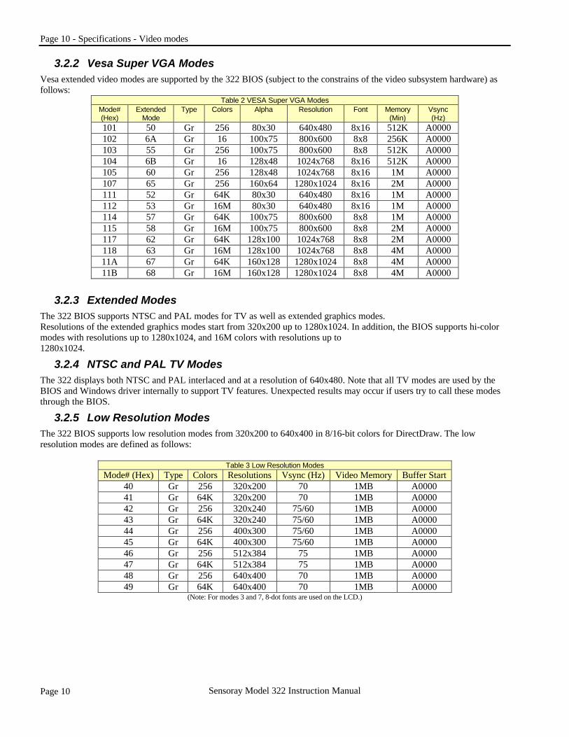
3.2.2 Vesa Super VGA Modes Vesa extended video modes are supported by the 322 BIOS (subject to the constrains of the video subsystem hardware) as follows:
Table 2 VESA Super VGA Modes Mode# (Hex)
Extended Mode
Type Colors Alpha Resolution Font Memory (Min)
Vsync (Hz)
101 50 Gr 256 80x30 640x480 8x16 512K A0000 102 6A Gr 16 100x75 800x600 8x8 256K A0000 103 55 Gr 256 100x75 800x600 8x8 512K A0000 104 6B Gr 16 128x48 1024x768 8x16 512K A0000 105 60 Gr 256 128x48 1024x768 8x16 1M A0000 107 65 Gr 256 160x64 1280x1024 8x16 2M A0000 111 52 Gr 64K 80x30 640x480 8x16 1M A0000 112 53 Gr 16M 80x30 640x480 8x16 1M A0000 114 57 Gr 64K 100x75 800x600 8x8 1M A0000 115 58 Gr 16M 100x75 800x600 8x8 2M A0000 117 62 Gr 64K 128x100 1024x768 8x8 2M A0000 118 63 Gr 16M 128x100 1024x768 8x8 4M A0000 11A 67 Gr 64K 160x128 1280x1024 8x8 4M A0000 11B 68 Gr 16M 160x128 1280x1024 8x8 4M A0000
3.2.3 Extended Modes The 322 BIOS supports NTSC and PAL modes for TV as well as extended graphics modes. Resolutions of the extended graphics modes start from 320x200 up to 1280x1024. In addition, the BIOS supports hi-color modes with resolutions up to 1280x1024, and 16M colors with resolutions up to 1280x1024.
3.2.4 NTSC and PAL TV Modes The 322 displays both NTSC and PAL interlaced and at a resolution of 640x480. Note that all TV modes are used by the BIOS and Windows driver internally to support TV features. Unexpected results may occur if users try to call these modes through the BIOS.
3.2.5 Low Resolution Modes The 322 BIOS supports low resolution modes from 320x200 to 640x400 in 8/16-bit colors for DirectDraw. The low resolution modes are defined as follows:
Table 3 Low Resolution Modes Mode# (Hex) Type Colors Resolutions Vsync (Hz) Video Memory Buffer Start
40 Gr 256 320x200 70 1MB A0000 41 Gr 64K 320x200 70 1MB A0000 42 Gr 256 320x240 75/60 1MB A0000 43 Gr 64K 320x240 75/60 1MB A0000 44 Gr 256 400x300 75/60 1MB A0000 45 Gr 64K 400x300 75/60 1MB A0000 46 Gr 256 512x384 75 1MB A0000 47 Gr 64K 512x384 75 1MB A0000 48 Gr 256 640x400 70 1MB A0000 49 Gr 64K 640x400 70 1MB A0000
(Note: For modes 3 and 7, 8-dot fonts are used on the LCD.)
Specifications - Video modes - Page 11
Page 11 Sensoray Model 322 Instruction Manual
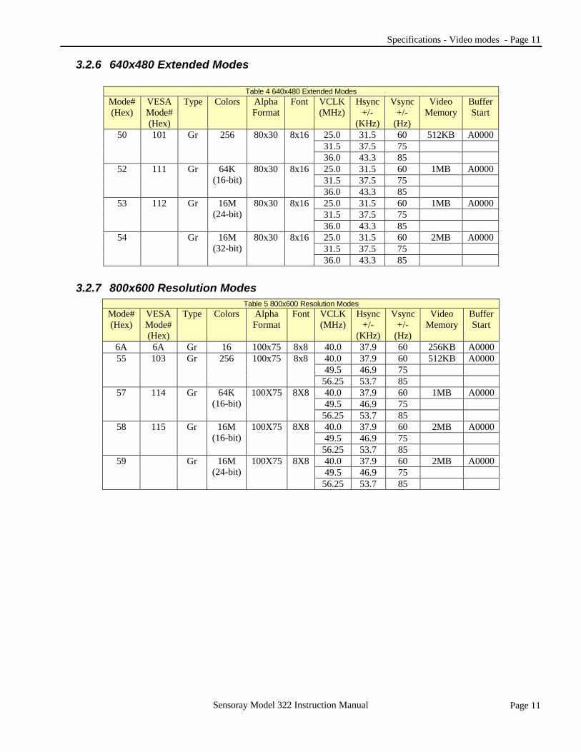
3.2.6 640x480 Extended Modes
Table 4 640x480 Extended Modes Mode# (Hex)
VESA Mode# (Hex)
Type Colors Alpha Format
Font VCLK (MHz)
Hsync +/-
(KHz)
Vsync +/-
(Hz)
Video Memory
Buffer Start
25.0 31.5 60 512KB A0000 31.5 37.5 75
50 101 Gr 256 80x30 8x16
36.0 43.3 85 25.0 31.5 60 1MB A0000 31.5 37.5 75
52 111 Gr 64K (16-bit)
80x30 8x16
36.0 43.3 85 25.0 31.5 60 1MB A0000 31.5 37.5 75
53 112 Gr 16M (24-bit)
80x30 8x16
36.0 43.3 85 25.0 31.5 60 2MB A0000 31.5 37.5 75
54 Gr 16M (32-bit)
80x30 8x16
36.0 43.3 85
3.2.7 800x600 Resolution Modes Table 5 800x600 Resolution Modes
Mode# (Hex)
VESA Mode# (Hex)
Type Colors Alpha Format
Font VCLK (MHz)
Hsync +/-
(KHz)
Vsync +/-
(Hz)
Video Memory
Buffer Start
6A 6A Gr 16 100x75 8x8 40.0 37.9 60 256KB A0000 40.0 37.9 60 512KB A0000 49.5 46.9 75
55
103
Gr
256
100x75
8x8
56.25 53.7 85 40.0 37.9 60 1MB A0000 49.5 46.9 75
57
114
Gr
64K (16-bit)
100X75
8X8
56.25 53.7 85 40.0 37.9 60 2MB A0000 49.5 46.9 75
58
115
Gr
16M (16-bit)
100X75
8X8
56.25 53.7 85 40.0 37.9 60 2MB A0000 49.5 46.9 75
59
Gr
16M (24-bit)
100X75
8X8
56.25 53.7 85

Page 12 - Specifications - Video modes
Page 12 Sensoray Model 322 Instruction Manual
3.2.8 1024x768 Extended Resolution Modes Table 6 1024x768 Extended Resolution Modes
Mode# (Hex)
VESA Mode# (Hex)
Type Colors Alpha Format
Font VCLK (MHz)
Hsync +/-
(KHz)
Vsync +/-
(Hz)
Video Memory
Buffer Start
6B 104 Gr 16 128x48 8x16 65.0 48.4 60 512KB A0000 65.0 48.4 60 1MB A0000 78.75 60.0 75
60
105
Gr
256
128x48
8x16
94.5 68.7 85 65.0 48.4 60 2MB A0000 78.75 60.0 75
62
117
Gr
64K (16-bit)
128x48
8x16
94.5 68.7 85 65.0 48.4 60 4MB A0000 78.75 60.0 75
63
118
Gr
16M (24-bit)
128x48
8x16
94.5 68.7 85 65.0 48.4 60 4MB A0000 78.75 60.0 75
64
Gr
16M (32-bit)
128x48
8x16
94.5 68.7 85 NOTE: For the above resolutions, the refresh rate for LCD and Simul mode is 60Hz.
3.2.9 1280x1024 Resolution Modes for CRT only Table 7 1280x1024 Resolution Modes for CRT only
Mode# (Hex)
VESA Mode# (Hex)
Type Colors Alpha Format
Font VCLK (MHz)
Hsync +/-
(KHz)
Vsync +/-
(Hz)
Video Memory
Buffer Start
65 107 Gr 256 160x64 8x16 78.75 47 43(I) 2MB A0000 67 11A Gr 64K 160x64 8x16 78.75 47 43(I) 4MB A0000 68 11B Gr 16M (24-bit) 160x64 8x16 78.75 47 43(I) 4MB A0000
3.2.10 1280x1024 Extended Modes for LCD only Table 8 1280x1024 Extended Modes for LCD only
Mode# (Hex)
VESA Mode# (Hex)
Type Colors Alpha Format
Font VCLK (MHz)
Hsync +/-
(KHz)
Vsync +/-
(Hz)
Video Memory
Buffer Start
65 107 Gr 256 160x64 8x16 85 50.3 47 2MB A0000 67 11A Gr 64K 160x64 8x16 85 50.3 47 4MB A0000 68 11B Gr 16M (24-bit) 160x64 8x16 85 50.3 47 4MB A0000
Note that Simul mode is not supported for 1280x1024 as well as interlaced modes.
3.2.11 1280x1024 Extended Modes Table 9 1280x1024 Extended Modes
Mode# (Hex)
VESA Mode# (Hex)
Type Colors Alpha Format
Font VCLK (MHz)
Hsync +/-
(KHz)
Vsync +/-
(Hz)
Video Memory
Buffer Start
78.75 47 43(I) 2MB A0000 108 64 60
65
107
Gr
256
160x64
8x16
135 79.98 75 78.75 47 43(I) 4MB A0000 108 64 60
67
11A
Gr
64K (16-bit)
160x64
8x16
135 79.98 75 78.75 47 43(I) 4MB A0000 108 64 60
68
11B
Gr
16M (24-bit)
160x64
8x16
135 79.98 75
Specifications - Driver support - Page 13
Page 13 Sensoray Model 322 Instruction Manual
3.3 Driver support MS-DOS using VGA BIOS MS Windows 95 MS Windows 98
MS Windows 2000 MS Windows NT LINUX
3.4 Board Size Size 4.5 x 3.8 x 0.6 inches (114 x 97 x 15 mm) Compatible with the PC/104+ specification, slightly wider to accommodate connectors. Weight Adapter only: 3.5 oz. (100 gm)
3.5 Power Specifications Power consumption: 3.75W, typical @ 5Vdc ±5%. This value will depend on the displays selected and the resolution being used.
3.6 Operating Environment Operating Temperature Range: 0°C to 70°C. Humidity: 5 to 95% relative humidity (non-condensing). Storage temperature: -55°C to +85°C.
3.7 Power On Configuration The 322 is configured to boot with the CRT display enabled and all other displays disabled. The default LCD type is set to 800x600 TFT. Contact Sensoray for other resolutions or for DSTN.
3.8 Supported LCD flat panels
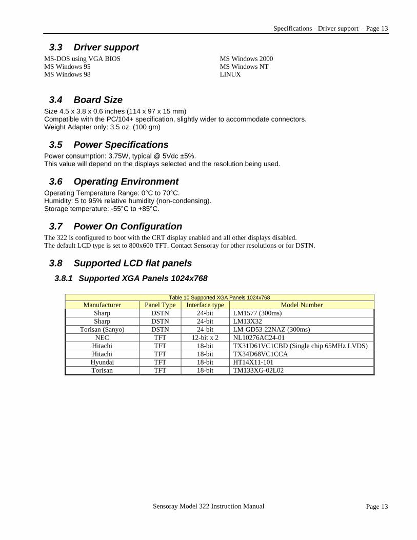
3.8.1 Supported XGA Panels 1024x768
Table 10 Supported XGA Panels 1024x768 Manufacturer Panel Type Interface type Model Number
Sharp DSTN 24-bit LM1577 (300ms) Sharp DSTN 24-bit LM13X32
Torisan (Sanyo) DSTN 24-bit LM-GD53-22NAZ (300ms) NEC TFT 12-bit x 2 NL10276AC24-01
Hitachi TFT 18-bit TX31D61VC1CBD (Single chip 65MHz LVDS) Hitachi TFT 18-bit TX34D68VC1CCA Hyundai TFT 18-bit HT14X11-101 Torisan TFT 18-bit TM133XG-02L02
Page 14 - Specifications - Supported LCD flat panels
Page 14 Sensoray Model 322 Instruction Manual
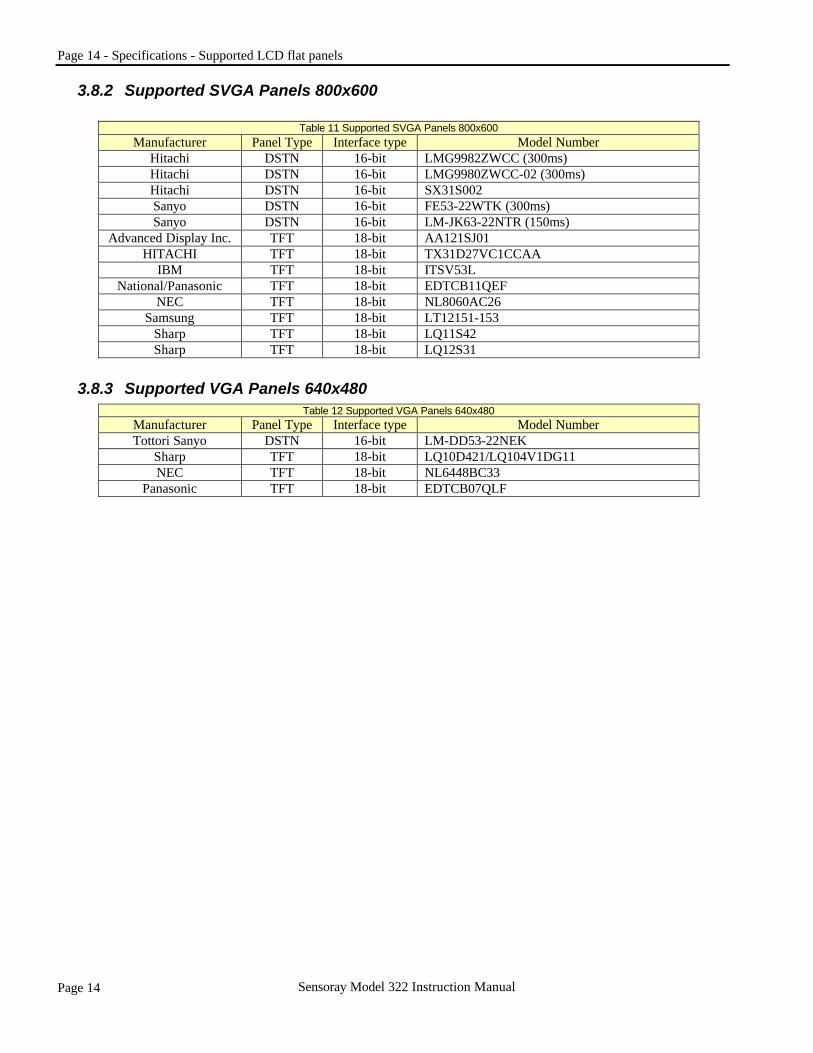
3.8.2 Supported SVGA Panels 800x600
Table 11 Supported SVGA Panels 800x600 Manufacturer Panel Type Interface type Model Number
Hitachi DSTN 16-bit LMG9982ZWCC (300ms) Hitachi DSTN 16-bit LMG9980ZWCC-02 (300ms) Hitachi DSTN 16-bit SX31S002 Sanyo DSTN 16-bit FE53-22WTK (300ms) Sanyo DSTN 16-bit LM-JK63-22NTR (150ms)
Advanced Display Inc. TFT 18-bit AA121SJ01 HITACHI TFT 18-bit TX31D27VC1CCAA
IBM TFT 18-bit ITSV53L National/Panasonic TFT 18-bit EDTCB11QEF
NEC TFT 18-bit NL8060AC26 Samsung TFT 18-bit LT12151-153
Sharp TFT 18-bit LQ11S42 Sharp TFT 18-bit LQ12S31
3.8.3 Supported VGA Panels 640x480 Table 12 Supported VGA Panels 640x480
Manufacturer Panel Type Interface type Model Number Tottori Sanyo DSTN 16-bit LM-DD53-22NEK
Sharp TFT 18-bit LQ10D421/LQ104V1DG11 NEC TFT 18-bit NL6448BC33
Panasonic TFT 18-bit EDTCB07QLF

Installation - Connector Information - Page 15
Page 15 Sensoray Model 322 Instruction Manual
3.9 Connector Information
3.9.1 CRT VGA Connector (J6) Any industry standard DB 15 male connector will plug into this connector. For pin outs see Table 15 Page 9
3.9.2 Composite Video connector (J3) Any industry standard male RCA type video (phone) jack will plug into this connector.
3.9.3 S-Video connector (J1) Any industry standard 4 pin male Mini Din connector will plug into this connector. For pin outs see Table 17 Page 16. Example: Digikey part# 2751029ND
3.9.4 Mixed Signal Header (J2) The connector mounted on the board is a 20 pin, shrouded, 2mm header. For pin outs see Table 16 Page 16. Molex part # 87331-2020. Consult Molex to find an IDC ribbon cable connector that will mate with this connector. Note When selecting a connector/cable combination for this connector make sure that the cable exits the connector in the correct direction so that it does not exit into the CRT VGA connector (J6).
3.9.5 LCD flat panel connector (J4) The connector mounted on the board is a 30 pin, shrouded, 2mm right angled header. For pin outs see Table 19 Page 17. Molex part# 87333-3020. Consult Molex to find an IDC ribbon cable connector that will mate with this connector.
4. Installation
4.1 Introduction This chapter describes how to configure, connect and install the Sensoray Model 322 PC104+ Video Graphics Adapter.
4.2 PCI Slot and Interrupt Jumper Configuration All PCI based systems require unique signal lines to be routed to each PCI slot. Because a PC/104+ system's cards are stacked and all the PCI signals are bussed, the PCI slot is selected on the individual expansion card. There is a set of jumpers on the 322 for PCI slot selection. Each PC/104+ card must have a unique slot number selected in order to avoid address conflicts. NOTE: The 322 cannot behave as a PCI bus master when setup for slot 3. This is because the PCI signals, GNT and REQ, are not connected for this slot.
4.2.1 PCI Slot Selection Check the legend printed on the printed circuit board alongside the slot selection jumpers (JP2, JP3, JP5, JP6) to determine the physical position of the jumper for the position shown in Table 13 above.
Table 13 PCI Slot Selection Slot number Jumper position
(Must be set the same on JP2, JP3, JP5, JP6) 0 2-4 1 4-6 2 1-3 3 3-5

Page 16 - Installation - CRT interfacing
Page 16 Sensoray Model 322 Instruction Manual
4.2.2 PCI Interrupt Selection The PCI interrupt that will be routed to the 322 is selected using JP4.
4.3 CRT interfacing The 322 has a standard 15-pin DB style VGA connector (J6) for easy CRT monitor interfacing. These signals are also available on the mixed signal header 20 pin 2mm metric header (J2). Only analog monitors are supported. The 322 supports nearly all compatible multi-frequency VGA type monitors. A pinout summary of the DB15 connector is given in Table 15 and of the Mixed signal header in Table 16. The CRT output signals are conditioned with ferrite beads on the board to minimize EMI (electromagnetic interference). Still, care should be taken to shield the embedded system and the video output cables to keep RF emissions as low as possible. FCC RF emissions regulations may apply to systems built with the 322. It is the responsibility of the customer to make their systems compliant with FCC regulations.
4.4 TV Interfacing The 322 has two TV outputs: A composite and a S-video output. A BNC, J3, is provided for the composite signals and a standard 4-pin Mini-DIN connector, J1, for the S-video signal. Standard video cables can be used to connect the 322 to either a NTSC or PAL TV monitor. Both of these sets of signals are also available on the mixed signal header J2. (See Table 16 P16).
Table 14 PCI Interrupt Interrupt JP4 jumper position.
A 2-4 B 4-6 C 1-3 D 3-5
Table 15 CRT DB15 (J6) pinout Table 16 Mixed Header (J2) pinout Pin Function Pin Function 1 Red 1 Signal Ground 2 Green 2 3 Blue 3 Signal Ground 4 N/C 4 5 Ground 5 Signal Ground 6 Signal Ground 6 Signal Ground 7 Signal Ground 7 Red 8 Signal Ground 8 Signal Ground 9 N/C 9 Green
10 Ground 10 Signal Ground 11 Ground 11 Blue 12 N/C 12 Signal Ground 13 Horizontal Sync 13 Ground 14 Vertical Sync 14 Horizontal Sync 15 N/C 15 Ground 16 Vertical Sync 17 Ground 18 Signal Ground 19 Composite Video 20 Signal Ground
Table 17 S-Video (J1) pinout Pin Function 1 Y-Out 2 C-Out 3 Signal ground 4 Signal ground

Installation - LCD interfacing - Page 17
Page 17 Sensoray Model 322 Instruction Manual
4.5 LCD interfacing
4.5.1 LCD Type Selection Prior to connecting the LCD panel jumpers JP7, JP8, JP9, JP10 must be set for either DSTN or TFT type panels.
All the signals needed for a variety of DSTN (16-bit) or TFT (9/12/18-bit) color LCD flat panels are provided on J4. The 322 uses 3.3V signaling and has CMOS outputs. Cable lengths should be kept short, if longer cables are required external buffering should be used. WARNING: Standard CMOS precautions should be observed with the 322 LCD outputs.
4.5.2 LCD Connector and Pinouts
The flat panel interface signals appear at the 30-pin 2mm metric header connector, J4, as shown in Table 19. Signal names are different for DSTN and TFT displays and there is no generally agreed upon standard among flat panel manufacturers. The names we use and the descriptions of the signal should provide enough information to connect either a DSTN or TFT flat panel. Signal descriptions R0-R5 - TFT red signal bits. G0-G5 - TFT green signal bits. B0-B5 - TFT blue signal bits. LD0-UD7 - Lower 8-bits of a 16-bit DSTN display. UD0-UD7 - Upper 8-bits of a 16-bit DSTN display. HSYNC - Horizontal Sync pulse for TFT displays. VSYNC - Vertical Sync pulse for TFT displays. LP - Load Pulse. A DSTN equivalent of HSYNC. XCK, CK - Flat panel shift clock. This is the pixel clock for flat
panel data. FP - Frame Load Pulse. A DSTN equivalent of VSYNC. ENABLE - Display Enable. This signal is used to indicate the
active horizontal display time. FPEN - Flat Panel enable. This signal needs to become active
after all panel voltages, clocks, and data are supplied. This signal also needs to become inactive before any panel voltages or control signals are removed.
VEE_EN - Panel Enable VEE. This is one of the two power sequencing signals that are used to control power lines connected to an LCD flat panel. This one is designed to properly control the VEE supply to the panel. See the following section for details.
VDD_EN - Panel Enable VDD. This is one of the two power sequencing signals that are used to control power lines connected to an LCD flat panel. This one is designed to properly control the main power to the panel. See the following section for details.
Table 18 LCD Type Selection Jumpers Type JP7, JP8, JP9, JP10 jumper positions.
DSTN 1-2 TFT 2-3
Table 19 LCD connector (J4) Pin Color DSTN Color TFT (1 pix/clk)
16-Bit 9-Bit 12-Bit 18-Bit 1 Ground Ground Ground Ground 2 Ground Ground Ground Ground 3 LD0 B0 B0 B0 4 LD1 B1 B1 B1 5 LD2 B2 B2 B2 6 LD3 Not used B3 B3 7 LD4 Not used Not used B4 8 LD5 Not used Not used B5 9 LD6 G0 G0 G0 10 LD7 G1 G1 G1 11 Ground Ground Ground Ground 12 UD2 G2 G2 G2 13 UD3 Not used G3 G3 14 UD0 Not used Not used G4 15 UD1 Not used Not used G5 16 UD4 R0 R0 R0 17 UD5 R1 R1 R1 18 UD6 R2 R2 R2 19 UD7 Not used R3 R3 20 Ground Ground Ground Ground 21 Not used Not used Not used R4 22 Not used Not used Not used R5 23 LP HSYNC HSYNC HSYNC 24 FP VSYNC VSYNC VSYNC 25 Not used ENABLE ENABLE ENABLE 26 FPEN FPEN FPEN FPEN 27 XCK CK CK CK 28 VDD_EN VDD_EN VDD_EN VDD_EN 29 Ground Ground Ground Ground 30 VEE_EN VEE_EN VEE_EN VEE_EN
Page 18 - Installation - Drivers
Page 18 Sensoray Model 322 Instruction Manual
4.5.3 LCD Power Sequencing Most LCD panels are sensitive to the order in which power and control signals are applied during start up and how they are removed during shut down. LCD panel manufacturers warn of damaging panels or limiting their life span unless proper precautions are taken. If an LCD display is used, you will need to provide power-switching circuits. Power sequencing requirements can vary from panel to panel. In general, however, the startup sequence is:
1. Apply VDD to the panel 2. Apply control and data signals 3. Apply VEE to the panel 4. Set FPEN active
Similarly, when powering down the sequence is:
1. Set FPEN inactive 2. Remove VEE from the panel 3. Remove control and data signals 4. Remove VDD from the panel
The 322 provides signaling for power sequencing that is compatible with most flat panels. The signals VEE_EN and VDD_EN are usually used to drive external power switches. The switch circuitry design depends on the requirements of the specific LCD display. Contact the display manufacturer for the required information.
4.6 Drivers Once the Sensoray 322 board is physically installed. Boot the operating system and choose to upgrade or install with one of the display device drivers provided by Sensoray. If any of the advanced features like rotation, display switching etc are to be used then download the control panel application. The same control panel install program is used for all the Windows products supported. This will integrate into the desktop display settings and allow the user to switch displays and exercise various other functions of the 322 board. Download the control panel from: (Approximately 10M).
BIOS - Overview - Page 19
Page 19 Sensoray Model 322 Instruction Manual
5. BIOS
5.1 Overview This section discusses the 322 BIOS functionality. The Bios includes all IBM standard VGA modes as well as extended VGA modes ranging from 640x480 up to 1280x1024 and VESA compatible modes. The BIOS also provides extended BIOS function calls for implementing various features of the 322.
5.2 BIOS Size and Format The 322 is supplied with a version of the BIOS burnt into about 48K of a 64K EPROM. The BIOS is also available as a RAM BIOS, which is a TSR version of the EPROM version. Contact Sensoray for further information.
5.3 Bios Features
5.3.1 Flat Panel Expansion A 1024x768 panel is expanded to 960x750 except for 640x480 resolution which is expanded to 960x720 for better display quality. For text expansion when using a 1024x768 panel, there is an option that if GPR0[7]=1, the BIOS expands text mode to 800x600 and centers the display.
5.3.2 NTSC/PAL TV Support The 322 is capable of driving a NTSC/PAL TV from an integrated TV encoder with Macrovision. The following items should be noted regarding the operation of this feature:
1. The display is interlaced because of TV requirement. 2. TV enable bit must be set. 3. The resolution for both NTSC and PAL is 640x480. 4. The CRT should not be driven when TV is driven. 5. TV only mode is supported. Two sets of new video modes (i.e., one for NTSC and one for PAL) are created to interface with this feature.
5.3.3 Display Switching The 322 supports various display settings that users can switch between. The video BIOS supports an INT 10h call to enable display switching and must determine whether the hardware necessary is available. Display switching can be from LCD, CRT, or Simul mode (LCD & CRT) to TV mode or from TV mode to LCD, CRT, or Simul mode.
5.3.3.1 Panel Power Sequencing The 322 supports flat panel power sequencing control in both hardware and software, which is defined by FPR34[7]
5.3.3.2 Hardware Panel Power Sequencing Control The 322 power-on setting selects hardware for panel power sequencing control with FPR34[7] =1. Panel power on/off is done by simply programming FPR31[0] from 0 to 1 to turn on panel display or from 1 to 0 to turn off panel display. Register FPR33[3:2] allows adjustment of the time interval between each panel control signal.
FPR33[3:2] Power On/Off Sequencing Time Select 00 1 vertical frame 01 2 vertical frames 10 4 vertical frames 11 8 vertical frames

Page 20 - BIOS - Standard IBM VGA Compatible BIOS Functions
Page 20 Sensoray Model 322 Instruction Manual
5.3.3.3 Software Panel Power Sequencing Control The software panel power sequencing control is set by FPR34[7] = 0. The example below assumes FPR33[3:2] = 00. To turn on flat panel:
• set FPR31[0] = 1 - enable LCD display • wait 1 vertical frame period, set PDR22[0] = 1 - turn on FPVDD • wait 1 vertical frame period, set PDR22[1] = 1 - enable flat panel interface outputs • wait 1 vertical frame period, set PDR22[2] = 1 - turn on panel bias voltage • wait 1 vertical frame period, set PDR22[3] = 1 - turn on FPEN output
To turn off flat panel:
• set PDR22[3] = 0 - turn off FPEN output • wait 1 vertical frame period, set PDR22[2] = 0 - turn off panel bias voltage • wait 1 vertical frame period, set PDR22[1] = 0 - disable flat panel interface outputs • wait 1 vertical frame period, set PDR22[0] = 0 - turn off FPVDD • set FPR31[0] = 1 - disable LCD display
5.4 Standard IBM VGA Compatible BIOS Functions The Bios supports all of the following the standard IBM Compatible BIOS calls. (Functions other than Set Mode are not supported in extended modes).
Table 20 Standard IBM VGA Compatible BIOS Functions Call # ax = Function
0x00xx Set Mode 0x01xx Set Cursor Type 0x02xx Set Cursor Position 0x03xx Read Cursor Position 0x05xx Select Active Display Page 0x06xx Scroll Active Page Up 0x07xx Scroll Active Page Down 0x08xx Read Attribute/Character at Cursor 0x09xx Write Attribute/Character at Cursor 0x0Axx Write Character Only at Cursor 0x0Bxx Set Color Palette, Background, or Border 0x0Cxx Write Pixel 0x0Dxx Read Pixel 0x0Exx Write TTY Character 0x0Fxx Read Current Video State 0x1000 Set Individual Palette Register 0x1001 Set Overscan Register 0x1002 Set All Palette and Overscan Register 0x1003 Toggle Blink/Intensity Bit 0x1007 Read Individual Palette Register 0x1008 Read Overscan Register 0x1009 Read All Palette and Overscan Register 0x1010 Set Individual Color Register 0x1012 Set Block of Color Registers 0x1013 Select Color Page 0x1015 Read Individual Color Register 0x1017 Read Block of Color Registers 0x1018 Write Pixel Mask
BIOS - Standard IBM VGA Compatible BIOS Functions - Page 21
Page 21 Sensoray Model 322 Instruction Manual
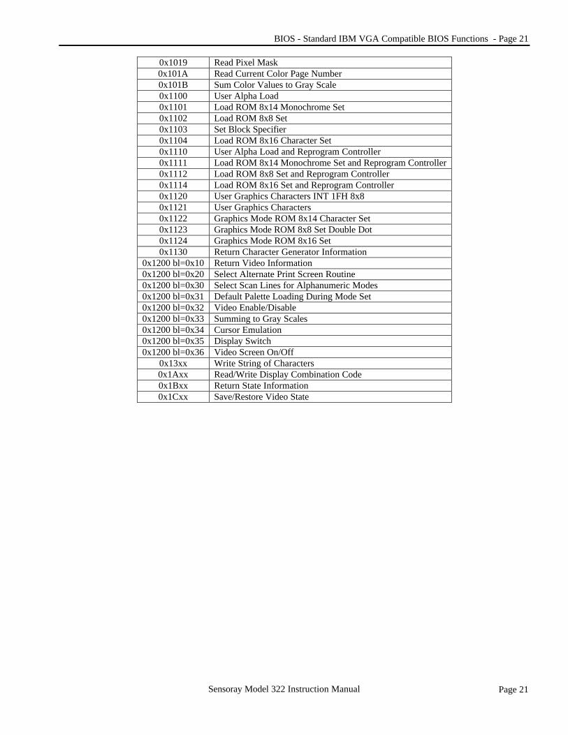
0x1019 Read Pixel Mask 0x101A Read Current Color Page Number 0x101B Sum Color Values to Gray Scale 0x1100 User Alpha Load 0x1101 Load ROM 8x14 Monochrome Set 0x1102 Load ROM 8x8 Set 0x1103 Set Block Specifier 0x1104 Load ROM 8x16 Character Set 0x1110 User Alpha Load and Reprogram Controller 0x1111 Load ROM 8x14 Monochrome Set and Reprogram Controller 0x1112 Load ROM 8x8 Set and Reprogram Controller 0x1114 Load ROM 8x16 Set and Reprogram Controller 0x1120 User Graphics Characters INT 1FH 8x8 0x1121 User Graphics Characters 0x1122 Graphics Mode ROM 8x14 Character Set 0x1123 Graphics Mode ROM 8x8 Set Double Dot 0x1124 Graphics Mode ROM 8x16 Set 0x1130 Return Character Generator Information
0x1200 bl=0x10 Return Video Information 0x1200 bl=0x20 Select Alternate Print Screen Routine 0x1200 bl=0x30 Select Scan Lines for Alphanumeric Modes 0x1200 bl=0x31 Default Palette Loading During Mode Set 0x1200 bl=0x32 Video Enable/Disable 0x1200 bl=0x33 Summing to Gray Scales 0x1200 bl=0x34 Cursor Emulation 0x1200 bl=0x35 Display Switch 0x1200 bl=0x36 Video Screen On/Off
0x13xx Write String of Characters 0x1Axx Read/Write Display Combination Code 0x1Bxx Return State Information 0x1Cxx Save/Restore Video State

Page 22 - BIOS - Extended BIOS Function Calls
Page 22 Sensoray Model 322 Instruction Manual
5.5 Extended BIOS Function Calls
Table 21 Extended BIOS Function Calls Call # ax = Function
5F00h Get Current VGA Information 5F05h Set Panel On 5F06h Set Panel Off 5F0Eh Monitor Detection 5F10h BX=0 PopUp Icon Control 5F10h BX=1 PopUp Icon Size 5F10h BX=2 PopUp Icon Location 5F10h BX=3 CH=1 PopUp Icon Color1 5F10h BX=3 CH=2 PopUp Icon Color2 5F10h BX=3 CH=3 PopUp Icon Color3 5F10h BX=5 Load PopUp Icon Bitmap 5F12h Display Switching Status 5F13h Switch Display To LCD 5F14h Switch Display To CRT (with monitor detection) 5F15h Switch Display To Simul 5F16h Switch Display To CRT (without monitor detection) 5F19h* Set Text Exp./Graphics Exp./Stretch 5F20h Set Extended Memory 5F21h Switch from LCD to TV 5F22h Switch from CRT to TV 5F23h Switch from Simul to TV 5F24h Switch from TV to LCD 5F25h Switch from TV to CRT 5F26h Switch from TV to Simul
5.5.1 Get Current VGA Information - 5F00h Returns the current VGA information. Input AX 5F00h Output AX Return status
0=Success, 1=Fail BX Chip ID CH Revision number CL Memory size in MB DH Display type 01=LCD Only 10=CRT Only 11=CRT/LCD (Simultaneous) DL Flat Panel type (FPR30)

BIOS - Extended BIOS Function Calls - Page 23
Page 23 Sensoray Model 322 Instruction Manual
5.5.2 Set Panel On - 5F05h Sets the panel ON. Input AX 5F05h Output AX Return status
0=Success, 1=Fail
5.5.3 Set Panel Off - 5F06h Sets the panel OFF. Input AX 5F06h Output AX Return status
0=Success, 1=Fail
5.5.4 Monitor Detection - 5F0Eh Detects if there is a monitor attached. Input AX 5F0Eh Output AX Return status
0=Success, 1=Fail BX 1=Monitor attached
0=No monitor
5.5.5 PopUp Icon Control - 5F10h Pups up the icon control on the screen. It is up to the user to define what the icon is. Input AX 5F10h BX 0 CL 0-disable
1-enable Output NONE

Page 24 - BIOS - Extended BIOS Function Calls
Page 24 Sensoray Model 322 Instruction Manual
5.5.6 PopUp Icon Size - 5F10h Defines the size of the icon. Input AX 5F10h BX 1 CL 0-64x64
1-128x128 Output NONE
5.5.7 PopUp Icon Location - 5F10h Defines the location of the icon on the screen. Input AX 5F10h BX 2 CX X Start (Pop90[7:0] & Pop91[2:0}) DX Y Start (Pop92[7:0] & POP93[2:0]) Output NONE
5.5.8 PopUp Icon Color1 - 5F10h Defines the first color of the icon. Input AX 5F10h BX 3 CH 1 (POP84) CL [7:0] color value Output NONE
5.5.9 PopUp Icon Color2 - 5F10h Defines the second color of icon. Input AX 5F10h BX 3 CH 2 (POP85) CL [7:0] color value Output NONE

BIOS - Extended BIOS Function Calls - Page 25
Page 25 Sensoray Model 322 Instruction Manual
5.5.10 PopUp Icon Color3 - 5F10h Defines the third color of icon. Input AX 5F10h BX 3 CH 3 (POP86) CL [7:0] color value Output NONE
5.5.11 PopUp Icon Bitmap - 5F10h Loads the bitmap file of icon. Input AX 5F10h BX 5 ES:SI Bitmap address (16 bit) Output NONE
5.5.12 Display Switching Status - 5F12h Called before switching takes place and returns the switching allowed status. Switching is not allowed as long as virtual refresh is on. There is no support fro this function call when in Dual Monitor mode and in the SMI special modes (Stretch and rotation). Input AX 5F12h Output ABL 0=OK to switch
1= Not allowed to switch
5.5.13 Switch Display to LCD - 5F13h Switches display to LCD in standard refresh mode. Input AX 5F13h Output AX 0=Success
1=Fail
Page 26 - BIOS - Extended BIOS Function Calls
Page 26 Sensoray Model 322 Instruction Manual
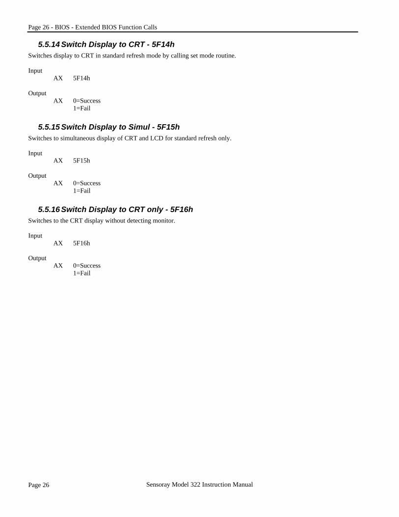
5.5.14 Switch Display to CRT - 5F14h Switches display to CRT in standard refresh mode by calling set mode routine. Input AX 5F14h Output AX 0=Success
1=Fail
5.5.15 Switch Display to Simul - 5F15h Switches to simultaneous display of CRT and LCD for standard refresh only. Input AX 5F15h Output AX 0=Success
1=Fail
5.5.16 Switch Display to CRT only - 5F16h Switches to the CRT display without detecting monitor. Input AX 5F16h Output AX 0=Success
1=Fail

BIOS - Extended BIOS Function Calls - Page 27
Page 27 Sensoray Model 322 Instruction Manual
5.5.17 Set Text Expansion/Graphics Expansion/Stretch - 5F19h Sets DOS modes text and graphics expansion and extended modes in stretch. Input AX 5F19h BH 1-get stretch/text expansion/graphics expansion status
0-set stretch/text expansion/graphics expansion BL Bit 0 0-text expansion off 1-text expansion on Bit 1 0-graphics expansion off 1-graphics expansion on Bit 2 0-stretch off 1-stretch on Bit 3 0-stretc/graphics/text status depends on bit [2,1,0] 1-stretch status overwrite DOS text and graphics mode Output AX 0=Success
1=Fail BL Text expansion/graphics expansion/stretch status (get status only)
All bit [3:0] parameters need to be provided Bit 0 0-text expansion off 1-text expansion on Bit 1 0-graphics expansion off 1-graphics expansion on Bit 2 0-stretch off 1-stretch on Bit 3 0-stretch/graphics/text status depends on bit [2,1,0] 1-stretch status overwrite DOS text and graphics mode When bit 3 =1, the status of bit [2:0] needs to be set the same way (either all 0 or all 1) When bit 3=0, the status of bit [2:0] can be set independently Note that BL does not return status for set function.
5.5.18 Set Extended Memory - 5F20h Sets the extended memory accessing environment for save/restore hotkey function. Input AX 5F20h Output NONE
5.5.19 Switch from LCD to TV display - 5F21h Switches from LCD mode to TV display mode. Input AX 5F21h Output AX 0=Success
1=Fail

Page 28 - BIOS - Extended BIOS Function Calls
Page 28 Sensoray Model 322 Instruction Manual
5.5.20 Switch from CRT to TV display - 5F22h Switches from CRT mode to TV display mode. Input AX 5F22h Output AX 0=Success
1=Fail
5.5.21 Switch from Simul to TV display - 5F23h Switches from Simul mode to TV display mode. Input AX 5F23h Output AX 0=Success
1=Fail
5.5.22 Switch from TV to LCD display - 5F24h Switches from TV mode to LCD display mode. Input AX 5F24h Output AX 0=Success
1=Fail
5.5.23 Switch from TV to CRT display - 5F25h Switches from TV mode to CRT display mode. Input AX 5F25h Output AX 0=Success
1=Fail
BIOS - Extended BIOS Function Calls - Page 29
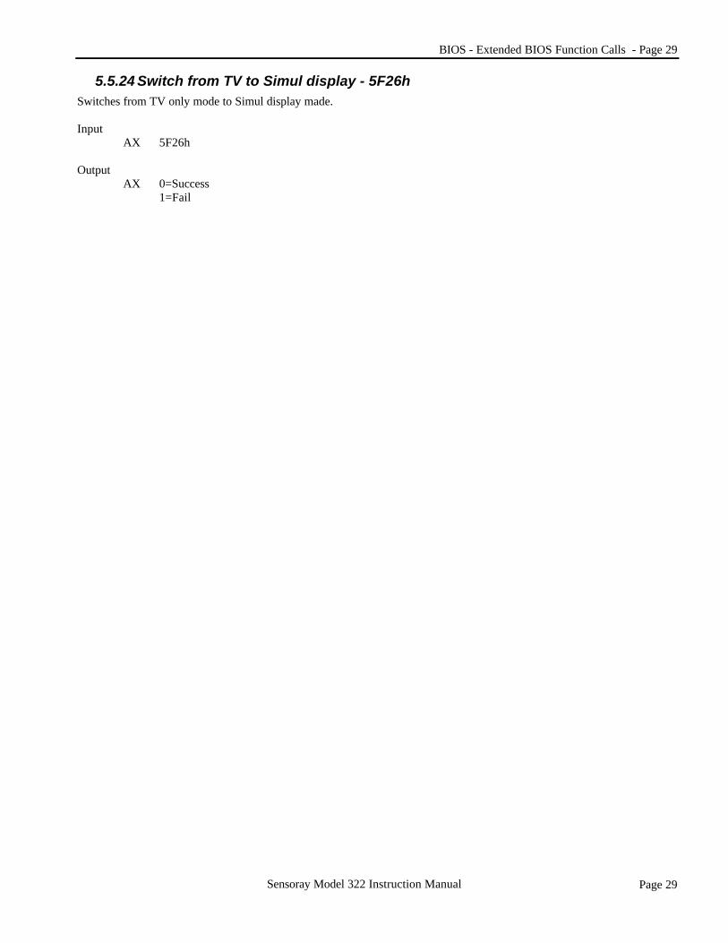
Page 29 Sensoray Model 322 Instruction Manual
5.5.24 Switch from TV to Simul display - 5F26h Switches from TV only mode to Simul display made. Input AX 5F26h Output AX 0=Success
1=Fail

Page 30 - BIOS - INT15 System BIOS Function Calls
Page 30 Sensoray Model 322 Instruction Manual
5.6 INT15 System BIOS Function Calls The 322 BIOS contains a number of INT15 system BIOS function calls. Each one of them provides the system BIOS an opportunity to gain control in the different VGA BIOS areas.
5.6.1 VGA POST Initialization - 7F00h Called prior to displaying VGA banner. Input AX 7F00h Output AX 007Fh Success
Else not supported
5.6.2 Get Panel ID - 7F01h Gets the panel ID. Input AX 7F01h Output AX 007Fh Success
Else not supported BL Panel ID (See below)
Note: There are 15 custom panel ID's specified by the BL register from 0 to 0eh. The value 0fh indicates the BIOS is using default panel timing.
Table 22 INT15 System BIOS function calls 7F00h VGA POST Initialization 7F01h Get Panel ID 7F02h Boot Display Device Override 7F03h Do Expansion/Centering 7F04h Normal Setmode/Special Setmode 7F05h Select TV Format 7F06h Get TV support status 7F07h Set subsystem and subvendor IDs 7F08h Set Text Exp./Graphics. Exp./Stretch initial status 7F09h Get Dual Monitor Support Status 7F0Ah Set TV DAC option 7F0Fh VGA POST Completion Signal
Table 23 Panel ID 00 640x480 TFT 01 640x480 DSTN 02 800x600 TFT 03 800x600 DSTN 04 1024x768 TFT 05 1024x768 DSTN 06 800x600 DSTN 75 Hz 07 Reserved 08 Reserved 09 Reserved 10 Reserved 11 Reserved 12 Reserved 13 Reserved 14 Reserved

BIOS - INT15 System BIOS Function Calls - Page 31
Page 31 Sensoray Model 322 Instruction Manual
5.6.3 Boot Display Device Override - 7F02h Determines the type(s) of display device during system bootup. If this function fails then BIOS would set to the default setting. Input AX 7F02h Output AX 007Fh Success
Else not supported BL Display type
01-LCD only 02-CRT only 03-LCD+CRT (Simultaneous)
5.6.4 Do Expansion or Centering - 7F03h Determines whether display should be in Expansion or centering mode. Input AX 7F03h Output BL 0-Centering mode
1-Expansion mode
5.6.5 Normal Set Mode or Special Set Mode - 7F04h Determines the set mode process is Normal or Special. Input AX 7F04h Output AX 007Fh-Normal Set mode
017fh-Special before 'Save to Disk' Set mode
5.6.6 Select TV Type - 7F05h Determines the TV type is either NTSC or PAL. Input AX 7F05h Output AX 007fh-NTSC
017fh-PAL
5.6.7 Get TV Support Status - 7F06h Determines if TV support is requested or not. Input AX 7F06h Output AX 007Fh-Need to check BL for TV support status
Else don't care (&F06h function not called) BL 0-no TV support
1-TV supported

Page 32 - BIOS - INT15 System BIOS Function Calls
Page 32 Sensoray Model 322 Instruction Manual
5.6.8 Set sub-vendor and sub-system ID's - 7F07h Returns sub-vendor and sub-system ID. Input AX 7F07h Output AX 007Fh BX Sub-system ID CX Sub-vendor ID
5.6.9 Select Text Expansion/Graphic Expansion/Stretch initial status - 7F08h Determines the power on initial status of expansion for text and graphics DOS modes and stretch for extended modes. Input AX 7F08h Output AX 007Fh Success BL Text Expansio/Graphics Expansion/Stretch status All Bit [3:0] parameters need to be provided Bit 0 0-text expansion off 1-text expansion on Bit 1 0-graphics expansion off 1-graphics expansion on Bit 2 0-stretch off 1-stretch on Bit 3 0-Stretch/Graphics/Text status depends on bit [2,1,0] 1-Stretch status overwrite DOS text graphics mode When bit3=1, the status of bit [2:0} needs to be set the same way (Either all 0 or all 1). When bit 3=0, the status of bit [2:0] can be set independently.
5.6.10 Get Dual Monitor Support Status - 7F09h Gets the dual monitor support status. Input AX 7F09h Output AX 007Fh Success BL 0-enable dual monitor support
1-disable dual monitor support
5.6.11 TV DAC Option - 7F0Ah Selects the TV DAC option. Input AX 7F0Ah Output AX 007Fh Success
Else fail BL[1:0] 00-SVHS off, CVBS off
01-SVHS off, CVBS on 10-SVHS on, CVBS off 11-SVHS on, CVBS on
Note: IF this function call is not used, the default is SVHS and CVBS DAC are both on. (BL[1:0]=11)

BIOS - INT15 System BIOS Function Calls - Page 33
Page 33 Sensoray Model 322 Instruction Manual
5.6.12 VGA POST Completion Signal - 7F0Fh Notifies system BIOS that VGA finished its initialization. Input AX 7F0Fh Output NONE
Page 34 - BIOS - VESA BIOS Functions
Page 34 Sensoray Model 322 Instruction Manual
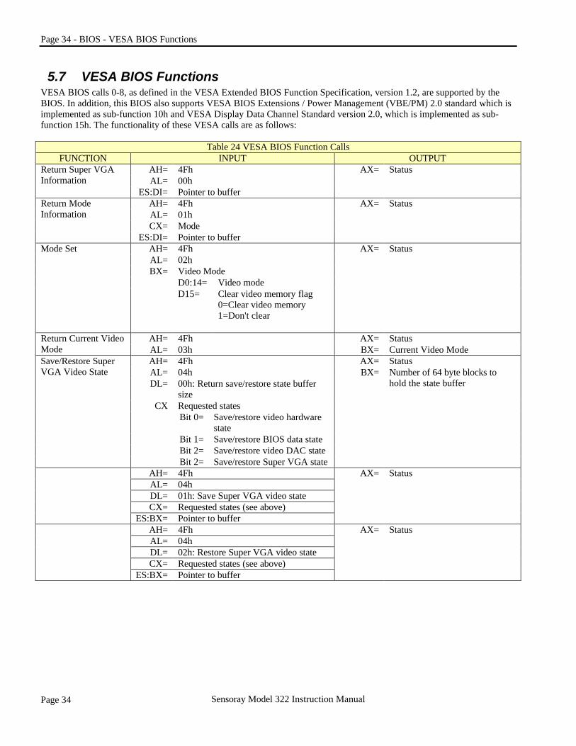
5.7 VESA BIOS Functions VESA BIOS calls 0-8, as defined in the VESA Extended BIOS Function Specification, version 1.2, are supported by the BIOS. In addition, this BIOS also supports VESA BIOS Extensions / Power Management (VBE/PM) 2.0 standard which is implemented as sub-function 10h and VESA Display Data Channel Standard version 2.0, which is implemented as sub-function 15h. The functionality of these VESA calls are as follows:
Table 24 VESA BIOS Function Calls FUNCTION INPUT OUTPUT
AH= 4Fh AX= Status AL= 00h
Return Super VGA Information
ES:DI= Pointer to buffer AH= 4Fh AX= Status AL= 01h CX= Mode
Return Mode Information
ES:DI= Pointer to buffer AH= 4Fh AL= 02h
Video Mode D0:14= Video mode
Mode Set
BX=
D15= Clear video memory flag 0=Clear video memory 1=Don't clear
AX= Status
AH= 4Fh AX= Status Return Current Video Mode AL= 03h BX= Current Video Mode
AH= 4Fh AX= Status AL= 04h DL= 00h: Return save/restore state buffer
size CX Requested states
Bit 0= Save/restore video hardware state
Bit 1= Save/restore BIOS data state Bit 2= Save/restore video DAC state
Save/Restore Super VGA Video State
Bit 2= Save/restore Super VGA state
BX= Number of 64 byte blocks to hold the state buffer
AH= 4Fh AL= 04h DL= 01h: Save Super VGA video state CX= Requested states (see above)
ES:BX= Pointer to buffer
AX= Status
AH= 4Fh AL= 04h DL= 02h: Restore Super VGA video state CX= Requested states (see above)
ES:BX= Pointer to buffer
AX= Status

BIOS - VESA BIOS Functions - Page 35
Page 35 Sensoray Model 322 Instruction Manual
Table 24 VESA BIOS Function Call - (Continued)
FUNCTION INPUT OUTPUT AH= 4Fh AL= 05h BH= 00h: Select window BL= Window Number
0=Window A 1=Window B
CPU Video Memory Window control
DX= Window position (in granularity units)
AX= Status
AH= 4Fh AX= Status AL= 05h BH= 01h: Return window
BL= Window Number 0=Window A 1=Window B
DX= Window position (in granularity units)
AH= 4Fh AX= Status AL= 06h BX= Bytes per scan line BH= 00h: Select scan line length CX= Actual picels per scan line
Set/Get Logical Scan
CX= Desired width in Pixels DX= Maximum number of scan lines AH= 4Fh AX= Status AL= 06hBX= BX= Bytes per scan line
CX= Actual pixels per scan line
BL= 01h: Return scan line length DX= Maximum # of scan lines
AH= 4Fh AL= 07h BH= 00h: Reserved and must be 0 BL= 00h: Select display start CX= First displayed pixel in scan line
Set/Get Display Start
DX= First displayed scan line
AX= Status
AH= 4Fh AX= Status AL= 07h BH= 00h Reserved and will be 0
CX= First displayed pixel in scan line
BL= 01h: Select display start DX= First displayed scan line
AH= 4Fh AX= Status AL= 08h BL= 00h
Set/Get DAC Palette Control
BH= Desired number of bits of color per primary (standard VGA=6)
BH= Current number of bits of color per primary (Standard VGA=6)
AH= 4Fh AX= Status AL= 08h
BL= 01h: Get DAC palette width BH= Current number of bits of color
per primary (Standard VGA=6)

Page 36 - BIOS - VESA BIOS Functions
Page 36 Sensoray Model 322 Instruction Manual
Table 24 VESA BIOS Function Call - (Continued)
FUNCTION INPUT OUTPUT AH= 4Fh AX= Status AL= 10h: VBE/PM Services BL= 00h: Report VBE/PM Capabilities CX= 00h: Controller unit number
(00=primary controller)
BH= Power saving state signals supported by the controller 1=supported 0=not supported bit 0- Standby bit 1- Suspend bit 2- Off bit 3- Reduced On bit 4-7 reserved
BL= VBE/PM Version number bit 0-3 Minor version # bit 4-7 Major version #
CX= Unchanged
Display Power Management Extensions
ES:DI= Null pointer, must be 0000:0000h in version 1.0
DX= Unchanged AH= 4Fh AL= 10h: VBE/PM Services
AX= Status (if requested state is not available, AX will return 014Fh)
BL= 01h: Set display power state BH= unchanged BH= Requested Power state
bit 0- Standby bit 1- Suspend bit 2- Off bit 3- Reduced On bit 4-7 reserved
CX= 00h: Controller unit number (00=primary controller)
CX= unchanged
AH= 4Fh AX= Status (if function is not supported, AL=01)
AL= 10h: VBE/PM Services BL= 02h: Get display power state
BH= Power state currently requested by the controller bit 0- Standby bit 1- Suspend bit 2- Off bit 3- Reduced On bit 4-7 reserved
CX= 00h: Controller unit number (00=primary controller)
CX= unchanged

BIOS - VESA BIOS Functions - Page 37
Page 37 Sensoray Model 322 Instruction Manual
Table 24 VESA BIOS Function Call - (Continued)
FUNCTION INPUT OUTPUT AH= 4Fh AX= Status AL= 15h: VBE/DDC Services BL= 00h: Report DDC Capabilities
BH= Approx. time in seconds, rounded up, to transfer one EDID block (128 byte)
BL= DDC level supported Bit 0 =0 DDC1 not supported
=1 DDC1 supported Bit 1 =0 DDC2 not supported
=1 DDC2 supported
Display identification extentions
CX= 00h: Controller unit number (00-primary controller)
Bit 2 =0 Screen not blanked during data transfer =1 Screen blanked during data transfer
AH= 4Fh AX= Status AL= 15h: VBE/DDC Services BL= 01h: Read EDID CX= 00h: Controller unit number (00-
primary controller) DX= 00h: EDID block number
ES:DI= Pointer to area in which the EDID block (128 bytes) shall be returned
ES:DI= Pointer to area in which the EDID block is returned
AH= 4Fh AX= Status AL= 15h: VBE/DDC Services BL= 02h: Read VDIF block CX= 00h: Controller unit number (00-
primary controller) DX= 00h: VDIF block number (64 bytes)
ES:DI= Pointer to area in which the VDIF block shall be returned
ES:DI= Pointer to area in which the VDIF block is returned
Page 38 - BIOS - BIOS Data Area Description
Page 38 Sensoray Model 322 Instruction Manual
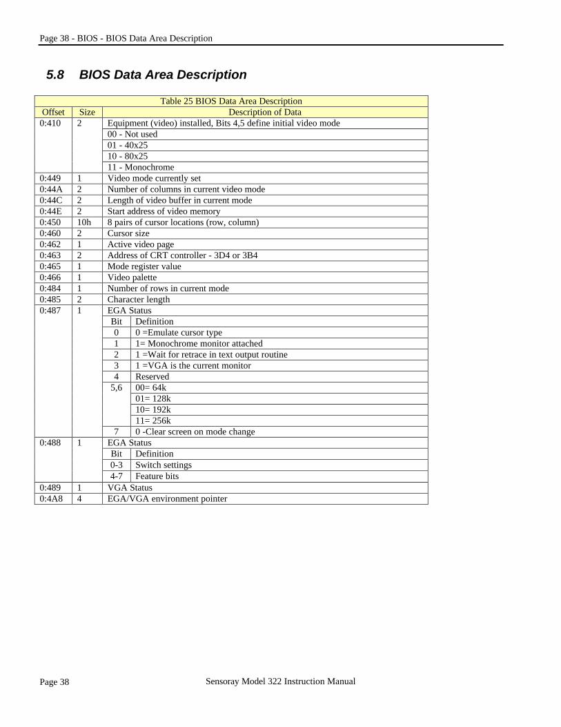
5.8 BIOS Data Area Description
Table 25 BIOS Data Area Description Offset Size Description of Data
Equipment (video) installed, Bits 4,5 define initial video mode 00 - Not used 01 - 40x25 10 - 80x25
0:410 2
11 - Monochrome 0:449 1 Video mode currently set 0:44A 2 Number of columns in current video mode 0:44C 2 Length of video buffer in current mode 0:44E 2 Start address of video memory 0:450 10h 8 pairs of cursor locations (row, column) 0:460 2 Cursor size 0:462 1 Active video page 0:463 2 Address of CRT controller - 3D4 or 3B4 0:465 1 Mode register value 0:466 1 Video palette 0:484 1 Number of rows in current mode 0:485 2 Character length
EGA Status Bit Definition 0 0 =Emulate cursor type 1 1= Monochrome monitor attached 2 1 =Wait for retrace in text output routine 3 1 =VGA is the current monitor 4 Reserved
00= 64k 01= 128k 10= 192k
5,6
11= 256k
0:487 1
7 0 -Clear screen on mode change EGA Status Bit Definition 0-3 Switch settings
0:488 1
4-7 Feature bits 0:489 1 VGA Status 0:4A8 4 EGA/VGA environment pointer

Appendix A: - Manual Revision Notes - Page 39
Page 39 Sensoray Model 322 Instruction Manual
Appendix A: Manual Revision Notes Date Revised by Description of changes 04/24/01 Dennis Manual first draft. 06/01/01 Dennis Added Software install information and a link to control panel on FTP site.
Appendix B: Technical Support For Technical support contact Sensoray Company Inc.
322 technical support email: [email protected] Home page: www.sensoray.com