instruction - sewingmachine.bysewingmachine.by/i/s/pdf/manual_138.pdf · instruction industrial...
TRANSCRIPT

INSTRUCTION
Industrial Sewing Machines
V7100/D,DE,F,ML W8100/D,DE,F,C W8042 W8042-1 V7002-1S W8103-1S
Third edition : March 2001
No. 010012

INTRODUCTIONINTRODUCTIONINTRODUCTIONINTRODUCTION Thank you for your purchasing Kansai Special's V.W Series. Read and study this instruction manual carefully before beginning any of the procedures and save it for later use.
1. This instruction manual describes adjustments and maintenance procedures on this
machine. 2. Before starting the machine, check to make sure the pulley cover, safety cover, etc.
are secured. 3. Before adjusting, cleaning, threading the machine or replacing the needle, be sure
to turn off the power. 4. Never start the machine with no oil in the reservoir. 5. Refer to the parts list as well as this instruction manual before performing
preventive maintenance. 6. The contents described in this instruction manual are subject to change without
notice.

CONTENTSCONTENTSCONTENTSCONTENTS
1. NEEDLES & THREADING THE MACHINE
1-1 Needles ・・・・・・・・・・・・・・・・・・・・・・・・・・・・・・・・・・・・・・・・・・・・・・・・・・・・・・ 1 1-2 Replacing the needle ・・・・・・・・・・・・・・・・・・・・・・・・・・・・・・・・・・・・・・・・・・ 1 1-3 Threading the machine ・・・・・・・・・・・・・・・・・・・・・・・・・・・・・・・・・・・・・・・・ 1
2. MACHINE SPEED 2-1 Machine speed & direction in which the machine pulley runs ・・・・・ 3 2-2 Motor & belt ・・・・・・・・・・・・・・・・・・・・・・・・・・・・・・・・・・・・・・・・・・・・・・・・・・ 3
3. LUBRICATION 3-1 Oil ・・・・・・・・・・・・・・・・・・・・・・・・・・・・・・・・・・・・・・・・・・・・・・・・・・・・・・・・・・・ 4 3-2 Oiling ・・・・・・・・・・・・・・・・・・・・・・・・・・・・・・・・・・・・・・・・・・・・・・・・・・・・・・・・ 4 3-3 Replacing the oil and the filter element ・・・・・・・・・・・・・・・・・・・・・・・・・ 4
4. SEWING MACHINE INSTALLATION 4-1 Cutting the machine table ・・・・・・・・・・・・・・・・・・・・・・・・・・・・・・・・・・・・・ 5 4-2 Installing the machine ・・・・・・・・・・・・・・・・・・・・・・・・・・・・・・・・・・・・・・・・・ 6
5. TIMING OF THE LOOPER TO THE NEEDLES 5-1 Angle and height for installing the looper ・・・・・・・・・・・・・・・・・・・・・・・ 6 5-2 Looper left-to-right movement ・・・・・・・・・・・・・・・・・・・・・・・・・・・・・・・・・・ 7 5-3 Needle height ・・・・・・・・・・・・・・・・・・・・・・・・・・・・・・・・・・・・・・・・・・・・・・・・・ 7 5-4 Length of the looper connecting bar ・・・・・・・・・・・・・・・・・・・・・・・・・・・・・ 7 5-5 Looper setting distance ・・・・・・・・・・・・・・・・・・・・・・・・・・・・・・・・・・・・・・・・ 8 5-6 Needle/looper front-to-back relationship ・・・・・・・・・・・・・・・・・・・・・・・・ 8
6. FRONT AND REAR NEEDLE GUARDS 6-1 Position of the needle guard (rear) ・・・・・・・・・・・・・・・・・・・・・・・・・・・・・・ 9 6-2 Position of the needle guard (front) ・・・・・・・・・・・・・・・・・・・・・・・・・・・・・ 9
7. ADJUSTING THE FEED DOGS & STITCH LENGTH 7-1 Feed dog height ・・・・・・・・・・・・・・・・・・・・・・・・・・・・・・・・・・・・・・・・・・・・・・10 7-2 Stitch length ・・・・・・・・・・・・・・・・・・・・・・・・・・・・・・・・・・・・・・・・・・・・・・・・・10 7-3 Differential feed ratio ・・・・・・・・・・・・・・・・・・・・・・・・・・・・・・・・・・・・・・・・10
8. ADJUSTING THE SPREADER 8-1 Position of the spreader ・・・・・・・・・・・・・・・・・・・・・・・・・・・・・・・・・・・・・・・11 8-2 Position of the spreader thread eyelet ・・・・・・・・・・・・・・・・・・・・・・・・・・11
9. ADJUSTING THE PRESSER FOOT 9-1 Presser foot pressure ・・・・・・・・・・・・・・・・・・・・・・・・・・・・・・・・・・・・・・・・・12 9-2 Position of the presser foot & foot lift ・・・・・・・・・・・・・・・・・・・・・・・・・・12
10. ADJUSTING THE STITCH FORMATION 10-1 Position of the needle thread eyelet ・・・・・・・・・・・・・・・・・・・・・・・・・・・・13 10-2 Position of the thread support ・・・・・・・・・・・・・・・・・・・・・・・・・・・・・・・・・13 10-3 Position of the spreader thread eyelet ・・・・・・・・・・・・・・・・・・・・・・・・・・13 10-4 Position of the thread eyelet of the looper thread take-up ・・・・・・・・14 10-5 Position of the looper thread take-up ・・・・・・・・・・・・・・・・・・・・・・・・・・14
11. CLEANING THE MACHINE ・・・・・・・・・・・・・・・・・・・・・・・・・・・・・・・14

1
< Note > Before replacing the needle, be sure to turn off the machine. A clutch motor continues running for a while after the machine is turned off. Therefore keep on pressing the pedal until the machine stops.
【1】NEEDLES & THREADING THE MACHINE 1111----1 Needles1 Needles1 Needles1 Needles
UY128GAS of Schmetz or Organ Select the proper needle for the fabric and thread. < Needles and needle size >
Schmetz UY128GAS Nm65 Nm70 Nm75 Nm80 Nm90 Organ
UY128GAS # 09 # 10 # 11 # 12 # 14
< Right needle of model-1S series > Schmetz TV7 Nm75 Organ TV7 # 11
1111----2 Replacing the needle2 Replacing the needle2 Replacing the needle2 Replacing the needle
When replace the needle, check the needle carefully to see that the scarf is turned to the rear of the machine (see the illustration). Then install the needle correctly.
1111----3 Threading the machine3 Threading the machine3 Threading the machine3 Threading the machine Thread the machine correctly by referring to the illustration below. Threading the machine incorrectly may cause skip stitching, thread breakage and/or uneven stitch formation.
A,B,C ... Needle threads D .............. Top cover thread E .............. Looper thread

2
A,B,C ... Needle threads D ............... Top cover thread E,F,G ... Looper thread
A,B,C,D ... Needle threads E ..................... Top cover thread F,G ............... Looper thread

3
【2】MACHINE SPEED 2222----1 Machine speed & direction in which the machine pulley runs1 Machine speed & direction in which the machine pulley runs1 Machine speed & direction in which the machine pulley runs1 Machine speed & direction in which the machine pulley runs
Refer to the table below for maximum and standard speeds of the Series. To extend machine life, run the machine approximately 15~20% below the maximum speed for the first 200 hours of operation (approx. 1 month). Then run the machine at the standard speed. The machine pulley turns counterclockwise as seen from the end of the machine pulley.
2222----2 Motor & belt2 Motor & belt2 Motor & belt2 Motor & belt
Motor : 3-phase, 2-pole, 400W clutch motor Belt : M type V belt Select the proper motor pulley according to the machine speed (refer to the motor pulley outer diameter on the table below). Adjust where to position the motor by pressing the finger onto the middle of the belt so that 1~2cm deflection can be obtained (see the illustration on the right).
< Machine speed > Type Maximum speed Standard speed
V7100 6000SPM 5500SPM W8100 5500SPM 5000SPM W8042-1 4500SPM 4000SPM W8103-1S 3000SPM 2500SPM
< Motor pulley selection table >
Machine speed (SPM)
Motor pulley outer diameter
(mm) 50Hz 60Hz 60 2500 2950 70 2900 3450 80 3300 3900 90 3700 4400 100 4100 4900 110 4500 5400 120 5000 5900 130 5300 (6400) 140 5800 (6900)

4
【3】LUBRICATION 3333----1 Oil1 Oil1 Oil1 Oil
Use Kansai Special’s genuine oil. (Part No. 28-611)
3333----2 Oiling2 Oiling2 Oiling2 Oiling ■ To fill the machine with oil
Remove rubber plug A from the oil hole. Fill the machine with oil until the oil level is at the top line (see H in the illustration) on oil gauge C. After the first lubrication, add oil so that the oil level will be between H and L. ■ To check for proper oil flow
After filling the machine with oil, run the machine to check the oil is splashing from oil pipe outlet B.
3333----3 Replacing the oil 3 Replacing the oil 3 Replacing the oil 3 Replacing the oil and the filter elementand the filter elementand the filter elementand the filter element
To extend machine life, be sure to replace the oil after the first 250 hours of operation. To replace the oil, follow the procedures below. 1. Remove the V belt from the motor pulley and
then remove the machine from the table. 2. Remove screw D and then drain the oil.
Be careful not to stain V belt with the oil. 3. After draining the oil, be sure to tighten screw
D. 4. Fill the machine with oil by referring to 3-2
shown above.
If filter element E is contaminated, proper oiling may not be performed. Clean the filter element every six months. If just a little or no oil flows out from the nozzle with the proper amount of oil in the machine, check the filter element. To clean the filter element, remove oil reservoir.

5
【4】SEWING MACHINE INSTALLATION 4444----1 Cutting the machine table1 Cutting the machine table1 Cutting the machine table1 Cutting the machine table

6
4444----2 Installing the machine2 Installing the machine2 Installing the machine2 Installing the machine Install the brackets on the underside of the table board (see the illustration below). Fit the rubber cushions onto the brackets. Mount the machine head on the rubber cushions.
【5】TIMING OF THE LOOPER TO THE NEEDLES
5555----1 Angle and height for installing the looper1 Angle and height for installing the looper1 Angle and height for installing the looper1 Angle and height for installing the looper To obtain the proper angle and height, insert the looper fully into looper holder A and then tighten screw B. The proper angle for the looper on V7100 and W8100 is 3°. Distance at 25mm from the point of the looper between the bottom of the looper blade and the extension line from the point of the looper : Approximately 1.3mm

7
5555----2 Looper left2 Looper left2 Looper left2 Looper left----totototo----right movementright movementright movementright movement When the point of the looper, moving to the left or right, has reached the left side of the left needle, distances As from the top of the left needle's eye to the point of the looper should be the same.(see the illustration on the right). To adjust the timing of the looper to the needles, remove the machine cover, loosen three screws C on eccentric B and then shift the eccentric by turning the machine pulley while holding the eccentric.
5555----3 Needle height3 Needle height3 Needle height3 Needle height When the needle bar is at the top of its stroke, adjust distance A from the top surface of the needle plate to the point of the left needle according to the gauge size in the table below. To make this adjustment, loosen nut B and move the needle bar up or down. On W8042 and W8042-1, use the front needle for reference.
Gauge size A (mm)
1/8 5/32 8.8 3/16 8.2 7/32 7.8
2-Needle
1/4 7.4 7/32 7.8 3-Needle 1/4 7.4
W8042 8.7 W8042-1 9.5 V7002-1S 9 W8103-1S 7.8
5555----4 Length of the looper connecting bar4 Length of the looper connecting bar4 Length of the looper connecting bar4 Length of the looper connecting bar Adjust distance A between two connecting rods according to pitch A in the table below (see the illustration on the right). Adjustment is made by loosening nuts B and turning connecting bar C as required.
Model Pitch A (mm) V7100 100 W8100 100 W8042 102
W8042-1 105

8
5555----5 Looper setting distance5 Looper setting distance5 Looper setting distance5 Looper setting distance Adjust setting distance A from the point of the looper to the center of the right needle when the looper is at the farthest position to the right. The point of the looper should be 1.2~1.5mm above the top of the left needle's eye when the point of the looper, moving to the right on the back side of the needles, has reached the left side of the left needle. Adjust distance A according to the needle space in the table below. Adjustment is made by loosening screw D (see the illustration in 5-4).
Needle space (inch)
Looper setting distance A
3.2mm (1/8) 5.0mm 4.0mm (5/32) 4.6mm 4.8mm (3/16) 4.2mm 5.6mm (7/32) 3.7mm 6.4mm (1/4) 3.5mm W8042 4.0mm W8042-1 4.5mm
5555----6 Needle/looper front6 Needle/looper front6 Needle/looper front6 Needle/looper front----totototo----back relationshipback relationshipback relationshipback relationship
The clearance between the right needle and the looper should be 0~0.05mm when the looper is moving on the back side of the needles. Adjustment is made by loosening screw A. The clearance between the left needle and the looper should be 0.2mm when the looper is moving on the back side of the needles. Adjustment is made by loosening screws B on the eccentric. To increase the clearance, turn the eccentric backward. To decrease the clearance, turn the eccentric frontward.
< Note > On W8042 and W8042-1, use the front needle for reference.

9
【6】FRONT AND REAR NEEDLE GUARDS 6666----1 Position of the needle guard (rear)1 Position of the needle guard (rear)1 Position of the needle guard (rear)1 Position of the needle guard (rear) ■Height adjustment
With needles down at bottom dead center adjust line a of needle guard A even with the center of the eye of the right needle. Adjustment is made by loosening screw D, raise or lower the guard as needed then tighten D. ■Clearance adjustment
Clearance between the needles and rear needle guard should be 0.0mm to 0.05mm. Adjust by loosening screw B and turning bushing C. Turn C clockwise to move the guard forward or counterclockwise to move the guard rearward. At this time tighten screw B slightly. ■On -1S
When the point of the looper has reached the center of the back side of the right needle, the distance from the point of the right needle to line A on the needle guard should be 0.8mm. At this time, there should be a 0mm clearance between the needle and the needle guard. Adjustment is made by loosening screw B. ■ On W8042 (fixed type)
When the needle bar is at the bottom of its stroke, the distance from line A to the point of the needle should be 3mm. Adjustment is made by loosening screw D. ■ On W8042-1
When the point of the looper has reached the right side of the needle, the distance from line A to the point of the needle should be 1mm and the clearance between the needle and the needle guard should be 0mm. Adjustment is made by loosening screw E. The height adjustment is made with adjusting screw F.
6666----2 Position of the needle guard (front)2 Position of the needle guard (front)2 Position of the needle guard (front)2 Position of the needle guard (front)
When the point of the looper has reached the center of the right needle, align the center of the right needle's eye with line A on the needle guard (front). Adjustment is made by loosening screw B. The clearance between the needles and the needle guard (front) should be 0.2~0.5mm. Adjustment is made by loosening screw C.

10
【7】ADJUSTING THE FEED DOGS & STITCH LENGTH 7777----1 Feed dog height1 Feed dog height1 Feed dog height1 Feed dog height
When the feed dogs are at the top of their stroke, the feed dog teeth should be 0.8~1.2mm above the top surface of the needle plate. Adjustment is made by loosening screws A and B.
7777----2 Stitch length2 Stitch length2 Stitch length2 Stitch length Loosen bolt A with a 9.5mm T wrench and turn screw B as required. To increase the stitch length, turn screw B counterclockwise. To decrease the stitch length, turn screw B clockwise.
7777----3 Differential feed ratio3 Differential feed ratio3 Differential feed ratio3 Differential feed ratio Remove rubber plug C. Loosen nut D. To increase the differential feed ratio, move nut D up. To decrease the differential feed ratio, move nut D down.
11
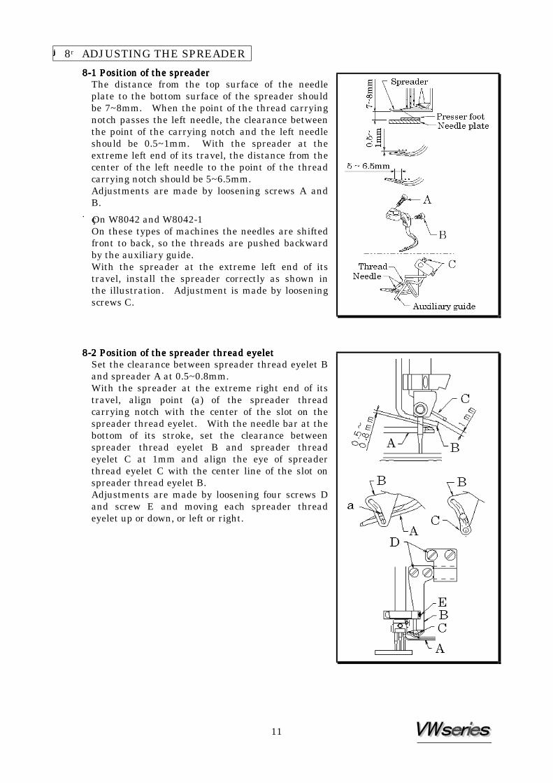
【【【【8】ADJUSTING THE SPREADER 8888----1 Position of the spreader1 Position of the spreader1 Position of the spreader1 Position of the spreader
The distance from the top surface of the needle plate to the bottom surface of the spreader should be 7~8mm. When the point of the thread carrying notch passes the left needle, the clearance between the point of the carrying notch and the left needle should be 0.5~1mm. With the spreader at the extreme left end of its travel, the distance from the center of the left needle to the point of the thread carrying notch should be 5~6.5mm. Adjustments are made by loosening screws A and B. ■ On W8042 and W8042-1
On these types of machines the needles are shifted front to back, so the threads are pushed backward by the auxiliary guide. With the spreader at the extreme left end of its travel, install the spreader correctly as shown in the illustration. Adjustment is made by loosening screws C.
8888----2 Position of the spreader thread eyelet2 Position of the spreader thread eyelet2 Position of the spreader thread eyelet2 Position of the spreader thread eyelet Set the clearance between spreader thread eyelet B and spreader A at 0.5~0.8mm. With the spreader at the extreme right end of its travel, align point (a) of the spreader thread carrying notch with the center of the slot on the spreader thread eyelet. With the needle bar at the bottom of its stroke, set the clearance between spreader thread eyelet B and spreader thread eyelet C at 1mm and align the eye of spreader thread eyelet C with the center line of the slot on spreader thread eyelet B. Adjustments are made by loosening four screws D and screw E and moving each spreader thread eyelet up or down, or left or right.

12
【9】ADJUSTING THE PRESSER FOOT 9999----1 Presser foot pressure1 Presser foot pressure1 Presser foot pressure1 Presser foot pressure
The presser foot pressure should be as light as possible, yet be sufficient to feed the fabric and produce uniform stitches. To increase the presser foot pressure, turn the adjusting knob clockwise.
9999----2 Position of the presser foot & foot lift2 Position of the presser foot & foot lift2 Position of the presser foot & foot lift2 Position of the presser foot & foot lift Fit the presser foot onto the presser bar so that the needle can drop correctly to the center of the presser foot needle drop hole. ■Position of the presser foot
Loosen screw A. Adjust by moving the presser foot left or right while checking to make sure the needle drops correctly to the center of the presser foot needle drop hole. ■Foot lift
For machines with the spreader, the presser foot should be 5mm above the top surface of the needle plate. Check to make sure presser foot does not touch the spreader with the presser foot in the above position. For machines without the spreader, the presser foot should be 6mm above the top surface of the needle plate.
After the proper foot lift is achieved, fit collar B onto the presser bar bushing and tighten screw C.

13
【10】ADJUSTING THE STITCH FORMATION 10101010----1 Position of the needle thread eyelet1 Position of the needle thread eyelet1 Position of the needle thread eyelet1 Position of the needle thread eyelet
The distance from the center of the eyelet of the needle thread eyelet to that of set screw A should be approximately 16mm (see the illustration). Adjustment is made by loosening screw A and moving the thread eyelet up or down. ■To tighten the needle thread, move the thread
guide up. ■To loosen the needle thread, move the thread guide
down.
10101010----2 Position of the thread support2 Position of the thread support2 Position of the thread support2 Position of the thread support With the needle bar at the bottom of its stroke, the centers of the eyes on thread eyelet A should be level with the top surface of thread support B and thread eyelet A should be parallel with thread support B. Adjust the height of thread support B by loosening screw C and moving thread support B up or down. ■To tighten the needle thread, move it up. ■To loosen the needle thread, move it down.
10101010----3 Position of the spreader thread eyelet3 Position of the spreader thread eyelet3 Position of the spreader thread eyelet3 Position of the spreader thread eyelet
With the needle bar at the top of its stroke, there should be a distance of approximately 13mm from the center of the eye of thread eyelet A to part (a) on thread eyelet B. Adjustment is made by loosening screw C and moving thread eyelet A up or down.

14
10101010----4 Position of the thread eyelet of the looper thread take4 Position of the thread eyelet of the looper thread take4 Position of the thread eyelet of the looper thread take4 Position of the thread eyelet of the looper thread take----upupupup Align the eyes on thread eyelets B and C with mark (a) on guide plate A. To increase the amount of looper thread to be supplied, move thread eyelets B and C to the back. To decrease the amount of looper thread to be supplied, move thread eyelets B and C to the front. Adjustment is made by loosening screws D. Set the distance from the top surface of guide plate A to the bottom surface of thread guide E at 6~7mm. Adjustment is made by loosening screw F. Adjust the thread eyelets of the thread take-up according to the thread and stitch length to be used.
10101010----5 Position of the looper thread take5 Position of the looper thread take5 Position of the looper thread take5 Position of the looper thread take----upupupup
When the point of the left needle has reached the bottom surface of the looper blade while the looper is moving from the extreme left end of its travel, the looper thread should be removed properly from highest position B on thread take-up A. Adjustment is made by loosening screw C.
【11】CLEANING THE MACHINE
At the end of each day, remove the presser foot and the needle plate and then clean the slots of the needle plate and the area around the feed dogs.