bma 0010 instruction and installation manual oil-air
TRANSCRIPT
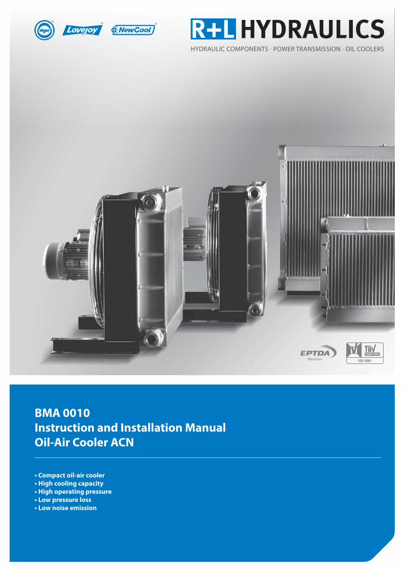
BMA 0010 Instruction and Installation Manual Oil-Air Cooler ACN
• Compact oil-air cooler• High cooling capacity• High operating pressure• Low pressure loss• Low noise emission
rl-hydraulics.com
2
1. Basic information 3
1.1 Notes on this Instruction and Installation Manual 31.2 Accuracy at time of going to press 31.3 Intended purpose 31.4 Warranty and liability 31.5 Guarantee and claims 31.6 Contact information 3
2. Safety 4
2.1 Standards and directives 42.2 Safety instructions – graphic design and form 42.3 Symbols used 42.4 Warning labels 42.5 General safety instructions 4
3. Description/specification 5
3.1 Sub-assemblies and options 53.2 Nameplate / identification label 5
4. Installation of the oil-air cooler 6
4.1 Installation site 6 → Installation in enclosed spaces 6 → Installation in the open 6 → Installation in dirty environments (spaces) 64.2 Installation mode and position 64.3 Electrical connections 6 → Terminal assignment 64.4 Hydraulic connection 6
5. Commissioning and start-up 7
6. Operating the unit 7
7. Maintenance 7
7.1 Regular maintenance work 77.2 Annual inspections: 7
8. Cleaning 8
8.1 Cleaning the radiator 88.2 Cleaning the inside of the cooler housing 8
9. Dismantling and assembling the sub-assemblies 8
9.1 Dismantling the radiator 89.2 Dismantling the electric motor and fan 9 → ACN 5 9 → ACN 10 – ACN 60 9 → ACN 70 – ACN 100 9
Contents
10. Important information for Ex-zones 10
10.1 Instruction manual supplement “Ex” 1010.2 Intended use 10 10.2.1 Explosive atmosphere 10 10.2.2 Instructions for use 1010.3 Industrial safety instructions 1010.4 Installation and assembly 1010.5 Checks, maintenance and repairs 1110.6 Testing 11
rl-hydraulics.com
3
1.1 Notes on this Instruction and Installation manual
1.2 Accuracy at time of going to press
1.3 Intended purpose
1.4 Warranty and liability
1.5 Guarantee and claims
1.6 Kontaktdaten
1. Basic information
Please read the installation manual carefully before installing and operating the ACN oil-air cooler; pay particular attention to the safety instructions. The Instruction and Installation Manual is part of your product. Keep the Manual in a safe place in the vicinity of the ACN oil-air cooler. Property rights to this Instruction and Instal-lation Manual remain with R+L HYDRAULICS GmbH.
We reserve the right to make technical amendments and alterations to reflect the current state of development. The ACN oil-air cooler described here represents the current state of the art at the time this Instruction and Installation Manual went to press.
The intended purpose of the ACN oil-air cooler is the cooling of hy-draulic fluid (mineral oil, HFC (polyglycol > 40%), HFD) in industrial plants and systems.
Unauthorised technical modifications to the ACN oil-air cooler are prohibited. Any such modifications are made entirely at the cus-tomer’s risk and exclude the manufacturer from any warranty claims or liability.
Please contact your R+L HYDRAULICS Partner in the event of any faults or breakdowns. R+L HYDRAULICS accepts no liability for any conse-quential loss or damage resulting from unauthorized repairs and/or modifications carried out by the customer.
R+L HYDRAULICS GmbHPostfach 1546D - 58775 WerdohlGermany
Phone: +49 (0) 2392 509-0Fax: +49 (0) 2392 509-509E-mail: [email protected]. rl-hydraulics.com
rl-hydraulics.com
4
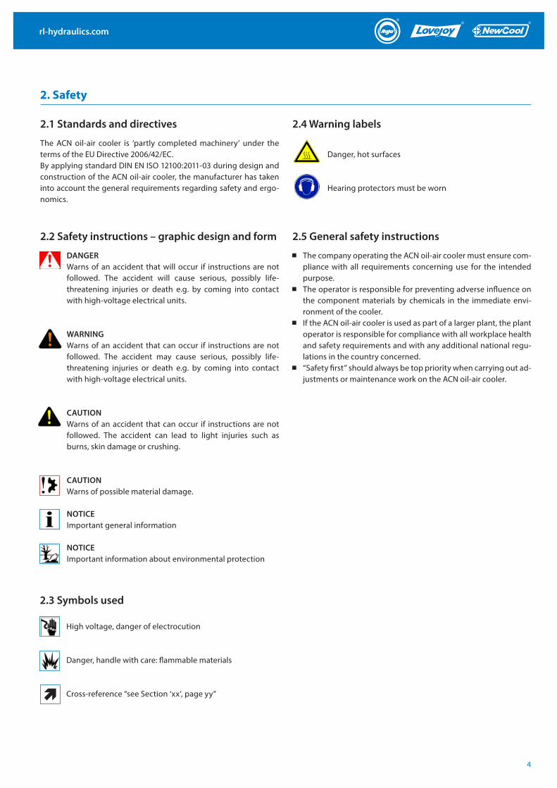
DANGERWarns of an accident that will occur if instructions are not followed. The accident will cause serious, possibly life-threatening injuries or death e.g. by coming into contact with high-voltage electrical units.
2.1 Standards and directives
2.2 Safety instructions – graphic design and form
2. Safety
The ACN oil-air cooler is ‘partly completed machinery’ under the terms of the EU Directive 2006/42/EC.By applying standard DIN EN ISO 12100:2011-03 during design and construction of the ACN oil-air cooler, the manufacturer has taken into account the general requirements regarding safety and ergo-nomics.
WARNINGWarns of an accident that can occur if instructions are not followed. The accident may cause serious, possibly life-threatening injuries or death e.g. by coming into contact with high-voltage electrical units.
CAUTIONWarns of an accident that can occur if instructions are not followed. The accident can lead to light injuries such as burns, skin damage or crushing.
CAUTIONWarns of possible material damage.
NOTICEImportant general information
NOTICEImportant information about environmental protection
High voltage, danger of electrocution
Danger, hot surfaces
Danger, handle with care: flammable materials
Hearing protectors must be worn
Cross-reference “see Section ‘xx’, page yy”
2.3 Symbols used
2.4 Warning labels
2.5 General safety instructions
The company operating the ACN oil-air cooler must ensure com-pliance with all requirements concerning use for the intended purpose.
The operator is responsible for preventing adverse influence on the component materials by chemicals in the immediate envi-ronment of the cooler.
If the ACN oil-air cooler is used as part of a larger plant, the plant operator is responsible for compliance with all workplace health and safety requirements and with any additional national regu-lations in the country concerned.
“Safety first” should always be top priority when carrying out ad-justments or maintenance work on the ACN oil-air cooler.
rl-hydraulics.com
5
3.1 Sub-assemblies and options 3.2 Nameplate
3. Description
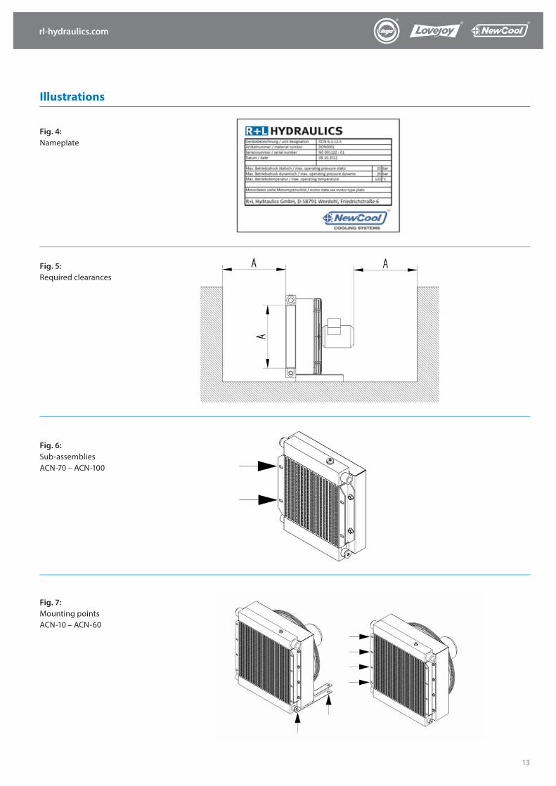
The main sub-assemblies of the ACN oil-air cooler are the radiator, the housing with mounting points and the fan sub-assembly, con-sisting of fan, protective grid and motor (æ see Appendix Fig. 1 and 2). The fan sub-assembly for sizes ACN 70 to ACN 100 also contains the motor console used for attaching the motor to the housing (æ see Appendix Fig. 3)
ACN oil-air coolers are available with one- or three-phase electric motors; detailed motor data can be found on the motor nameplate.
Optional thermostat switches are available; these can be screwed into the radiator and activate the fan automatically when the sys-tem temperature reaches a certain level. The necessary motor con-trols must be installed beforehand.
Under normal operating conditions, the noise emission level of oil-air coolers of sizes ACN 5 to ACN 100 is between 61dB(A) and 84dB(A) +/- 3dB(A). These values can be exceeded if the device is in-stalled in an unfavourable location or operated under extreme con-ditions.
For general information on dimensions and technical data æ see Appendix, Section “Technical Data and Dimensions”.
Every ACN oil-air cooler is fitted with a nameplate containing the following data (æ see Appendix Fig. 4) and located on the top of the housing:
Article name Article number Serial number Delivery date Max. operating pressure, static Max. operating pressure, dynamic Max. operating temperature
rl-hydraulics.com
6
4. Installation of the oil-air cooler
CAUTIONRisk of crushing! To avoid accidents and injuries when lift-ing, use only the appropriate hoisting equipment and pro-cedures. Ensure that the hoisting machinery and equip-ment used are in perfect working order and approved for the weight of the oil/air cooler!
4.1 Installation siteWhen selecting the installation site, please ensure that it will have no adverse effects on the function of the ACN oil-air cooler and that draughts or noise will not inconvenience or harm personnel. Air inlets and outlets must not be covered or blocked at any time, so that cooling air can circulate freely. Recirculation of hot air (exhaust) must be avoided. Please ensure that the distance between the cool-er and the nearest wall is equal to or larger than the height of the cooling package. (æ see Appendix Fig. 5)
Installation in enclosed spaces When the equipment is installed in enclosed spaces, adequate ven-tilation must be provided so that the warm air produced by the heat exchange process does not increase the temperature in the room. If adequate ventilation cannot be provided, air ducts must be in-stalled between the ACN oil-air cooler and the outside air, allow-ing air to be sucked directly into the cooler and provide the venti-lation required.
Outdoor installationThe increased viscosity of oil at low ambient temperatures must be taken into consideration when installing the heat exchang-er outdoors. This can lead to increased dynamic pressure and sys-tem overload when starting from cold, so we recommend the in-stallation of a bypass valve controlled by pressure or temperature if the cooler is installed outdoors. As an alternative, a thermostat-ically controlled oil heating system with permanent oil circulation through the ACN oil-water cooler can be fitted.
Installation in dirty environments (spaces)Installing the heat exchanger in environments with heavily contam-inated air results in dirt deposits on the cooling fins. As this reduces the cooling performance, the equipment must be cleaned regular-ly when installed in environments strongly contaminated with dust or oil (æ see Appendix Fig. 8. Cleaning).
DANGERRisk of electrocution! Electrical equipment must be installed and connected to the mains by a qualified electrician!
DANGERRisk of electrocution! Ensure that the device is not connect-ed to the mains electricity supply during installation!
CAUTIONCheck mains voltage and frequency! To avoid damage to the ACN oil-air cooler or electrical systems, always compare the information regarding mains voltage and frequency given on the motor nameplate before connecting the oil-air cool-er to the mains and.
WARNINGOverload protection! Electric motors must be properly pro-tected against overload in accordance with the customary technical rules and national regulations.
4.2 Installation position and orientation
4.3 Electrical connections
The installation position does not affect the function of the ACN oil-air cooler. However, only the mounting points provided should be used (æ see Appendix Figs. 6 – 8).ACN 5: front mounting flangeACN 10 – 60: Foot brackets or front mounting flangeACN 70 – 100: Foot brackets or front mounting flange
WARNINGConnection must be free of tension and vibration! To pre-vent damage to the radiator, all hydraulic connections should be free of tension or vibration. R+L HYDRAULICS rec-ommends the use of suitable hydraulic lines or compensa-tors for the connection of the ACN oil-air cooler.
4.4 Hydraulic connections
The oil-side connection of the ACN oil-air cooler is effected using the marked connection threads or flanges provided on the upper and lower collection tanks of the radiator (æ see Appendix Fig. 11 + 12). The connection not in use is sealed with a sealing plug before leav-ing our factory. The connecting pipes G 3/8” and M22 x 1.5 (ACN 5 – ACN 60) or G 1” (ACN 70 – ACN 100) are intended for the installation of measuring sensors or switches (æ see Appendix Fig. 13).
rl-hydraulics.com
7
5. Commissioning and start-up
6. Operating the unit
7. Maintenance
CAUTIONRisk of injury! Before operating for the first time, check that the ACN oil-air cooler has been installed and connected cor-rectly.
CAUTIONRisk of burns or scalding! The ACN oil-air cooler can become very hot when in operation, so always allow ample time for the radiator to cool down before touching it. We recom-mend the installation of a guard to prevent accidental con-tact.
Commissioning and start-up procedure: Please ensure that:
→ the ACN oil-air cooler is complete and none of the compo-nents show signs of damage.
→ the ACN oil-air cooler has been connected correctly. → the fan can rotate freely and without obstruction - a simple
test is to turn the fan by hand. To prevent obstruction or dam-age to the fan blades, ensure that there is nothing protruding through the fan guard.
→ all screw-in oil connections have been sufficiently tightened. → the housing of the ACN oil-air cooler is free of foreign objects.
Please ensure that the following maximum permissible values/lim-its are not exceeded during operation. Max. oil temperature: 120 °CMax. ambient temperature: 40 °CMax. operating pressure: 26 bar static / 20 bar dynamic Max. power consumption: see motor nameplate
The user/operator should check the following items at regular in-tervals to ensure that the ACN oil-air cooler continues to function properly and safely:
Noise and vibration: Unusual noises or vibration indicate that the fan or drive motor
may be damaged. Damaged components must be replaced im-mediately. (æ see Appendix Section 9.2 Dismantling the electric motor and fan)
Correct mounting: Loose or missing mountings must be tightened or replaced.
Soiling of the radiator: Dirt on the radiator will reduce cooling performance and may be
an indication of leaks, so the radiator must be cleaned regularly. (æ see Section 8.1 Cleaning the radiator)
7.1 Regular maintenance work
The electrical installations must be checked by a suitably qualified electrician once a year.
7.2 Yearly inspections:
Turned on the oil supply and check the hydraulic connections for possible leaks.
In the event of a leak, retighten the screw connections; if neces-sary, replace the connections.
Start the electric motor. Check that the fan is rotating in the di-rection of the arrow on the housing.
If a three-phase motor is fitted and the fan is rotating in the wrong direction, reverse the terminal connections.
Listen carefully for any unusual noises or vibration. Unusual noises or vibration indicate that the fan or drive motor
may be damaged. Damaged components must be replaced im-mediately (æ see Appendix Section 9.2 Dismantling the electric motor and fan).
Oil-tightness of the radiator: Oil leaks can endanger the environment and constitute a risk to
human health, so any leaky screw connections must be tight-ened or replaced. If oil is leaking from the radiator itself, the radi-ator must be replaced. (æ see Section 9.1 Dismantling the radia-tor)
Warning labels: Warning labels must not be damaged or removed. Any defaced
or missing labels must be replaced immediately.
rl-hydraulics.com
8
9. Dismantling and assembling the sub-assemblies
8. Cleaning
R+L Hydraulics accepts no liability for consequential damage caused by unauthorised repairs and/or modifications carried out by the user/operator.
The radiator may be cleaned with compressed air or water. If the ra-diator is extremely dirty, it can also be cleaned with water using a high-pressure cleaner. The water jet must be directed lengthwise along the fins to avoid damaging them. Add a cleaning agent to the water if necessary, but please ensure that the cleaning agent used is compatible with aluminium. Oil and grease deposits can be washed off with hot water. Always cover the motor during clean-ing and ensure that the radiator is cold when cleaning it with water.
The radiator must be removed in order to clean the inside of the cooler housing (æ see Section 9.1 Dismantling the radiator). As a rule, cleaning the cooler housing with compressed air at is suffi-cient. To prevent dust and dirt from entering the motor, we recom-mend directing compressed air through the protective grid from the motor side. Particularly stubborn dirt can be removed using a degreaser.
9.1 Dismantling the radiator
8.1 Cleaning the radiator
8.2 Cleaning the inside of the cooler housingDANGERRisk of electrocution! Always disconnect the ACN oil-air cooler from the mains electricity supply during cleaning, es-pecially when water or other liquids are used.
CAUTIONRisk of injury! Always switch off drive motor before disman-tling the radiator and ensure that it cannot be switched on again inadvertently.
CAUTIONRisk of injury! Always switch off drive motor before clean-ing and ensure that it cannot be switched on again inadvert-ently.
CAUTIONRisk of burns or scalding! The ACN oil-air cooler can become very hot when in operation, so always allow ample time for the radiator to cool down before dismantling.
CAUTIONRisk of burns or scalding! The ACN oil-air cooler can become very hot when in operation, so always allow ample time for the radiator to cool down before touching it. We recom-mend the installation of a guard to prevent accidental con-tact.
CAUTIONRisk of crushing! To avoid injuries caused by the radiator fall-ing, always secure it before loosening the fixing screw.
Procedure for dismantling the radiator (æ see Appendix Fig. 14): Turn the system off. Switch off fan motor and ensure that it cannot be restarted inad-
vertently. Make sure that the system is not under pressure. Shut off oil supply to the cooler. Remove cooler inlet and outlet pipes. Empty radiator completely. Remove the screws fixing the radiator to the housing. Remove the radiator.
Procedure for assembling the radiator: Refit radiator Attach the radiator to the housing with the screws provided.
Secure screws with Loctite blue or similar liquid thread locker. Attach cooler inlet and outlet pipes to the radiator. Connect motor to the electricity supply.
rl-hydraulics.com
9
9. Dismantling and assembling the sub-assemblies
9.2 Dismantling the electric motor and fan
DANGERRisk of electrocution! Ensure that the unit has been discon-nected from the mains electricity supply and the electrical wiring is current-free before dismantling des electric motor!
CAUTIONRisk of burns or scalding! The ACN oil-air cooler can become very hot when in operation, so always allow ample time for the radiator to cool down before dismantling the electric motor.
ACN 5Procedure for dismantling the electric motor (æ see Appendix Fig. 15):
Turn off the unit and ensure that it is completely disconnected from the mains electricity supply.
Disconnect wiring to and from the motor. Remove screws fastening the protective grid to the frame.
Procedure for installing the electric motor: Fasten protective grid to housing with screws and washers.
Secure screws with Loctite blue or similar liquid thread locker. Connect motor to the mains electricity supply. For subsequent procedures, see Section 5. “Commissioning and
start-up”.
ACN 10 – ACN 60Procedure for dismantling the electric motor (æ see Appendix Fig. 16):
Turn off the unit and ensure that it is completely disconnected from the mains electricity supply.
Disconnect wiring to and from the motor. Secure the motor. Remove screws fastening the protective grid to the frame. Remove fan unit - consisting of protective grid, fan and motor –
from the cooler housing. Remove locking screw at the front end of the motor shaft. Remove fan from motor shaft, using a puller if necessary. Release locking screws between protective grid and motor. Remove protective grid.
Procedure for installing the electric motor: Attach protective grid to the motor. Fasten protective grid to the motor with screws provided. Secure
screws with Loctite blue or similar liquid thread locker. After lightly greasing the motor shaft, fit the fan on the shaft, us-
ing a spacer ring if necessary. Securely fasten fan to front end of motor shaft using screw and
suitable washer(s). Attach fan unit – consisting of protective grid, fan and motor - to
cooler housing.
Fasten protective grid to housing with screws and washers. Se-cure screws against loosening with Loctite blue or similar liquid thread locker.
Check that the fan is centred in its housing and able to rotate freely. If necessary, slightly loosen screws between protective grid and housing, then realign protective grid.
Connect motor to the mains electricity supply. For subsequent procedures, see Section 5. “Commissioning and
start-up”.
ACN 70 – ACN 100Procedure for dismantling the electric motor (æ see Appendix Fig. 17):
Turn off the unit and ensure that it is completely disconnected from the mains electricity supply.
Disconnect wiring to and from the motor. Secure the motor. Release the screws fastening the protective grid to the housing. Release the screws fastening the motor console to the housing. Remove fan unit – consisting of protective grid, fan, motor con-
sole and motor – from the cooler housing. Remove locking screw at the front end of the motor shaft. Remove fan from motor shaft, using a puller if necessary. Remove protective grid. Remove screws fastening the motor console to the motor. Remove motor console.
Procedure for installing the electric motor: Attach motor console to motor. Fasten motor console to motor with screws provided. Secure
screws with Loctite blue or similar liquid thread locker. Lay protective grid on motor console. After lightly greasing the motor shaft, fit the fan on the shaft. Securely fasten fan to front end of motor shaft using screw and
suitable washer(s). Secure screw against loosening with Loctite blue or similar liquid thread locker.
Attach fan unit – consisting of protective grid, fan, motor console and motor – to the housing.
Securely fasten motor console to housing with screws and wash-ers. Secure screws against loosening with Loctite blue or similar liquid thread locker.
Securely fasten protective grid to housing with screws and wash-ers. Secure screws against loosening with Loctite blue or similar liquid thread locker.
Check that the fan is centred in its housing and able to rotate freely. If necessary, slightly loosen screws between motor con-sole and housing and realign motor console.
Connect motor to the mains electricity supply. For subsequent procedures, see Section 5. “Commissioning and
start-up”.
rl-hydraulics.com
10
10. Important information for Ex-zones
If the oil-air filter ACN is operated in or in connection with an ex-plosive atmosphere, the following supplementary instructions in the “Instruction Manual Ex” must be followed in ad-dition to the in-structions in the specification “ACN and DCN oil-air filter” and “BMA 0010 Operating Manual and Fitting Instructions / oil-air filter ACN”.
The oil-air filter is a component under the terms of RL 94/9/EC and may only be operated in or in connection with an explosive atmos-phere if the conditions below are met.
10.1 Instruction manual supplement “Ex”
10.2 Intended use
10.3 Industrial safety instructions
10.2.1 Explosive atmosphere
Ambient pressure pU 0.8 to 1.1 barOperation is forbidden in an explosive atmosphere resulting from explosive dust or unstable substances as defined in RL 67/548/EEC.
10.2.2 Instructions for use
The oil-air filter was designed to be free of ignition sources in ac-cordance with DIN EN 14986. The oil-air filter is available in versions suitable for the following categories: For use in Zone 1 or Zone 2:CE II 2 G IIB TXFor use in Zone 22:CE II 3 D TX.The minimum ignition energy of combustible dusts is:MZE ≥ 10 mJPermissible ambient temperature is:-20 °C ≤ TU ≤ +40 °C
Maximum surface temperature is dependent on the oil involved. Maximum surface tempera-ture is identical with maximum oil tem-perature. The ignition temperature of the oil to be cooled must be at least 50°C higher than the maximum permissible surface temperature.The presence of dust in the cooling air can cause inadmissible elec-trostatic charging of the powder coating of the cooler and housing, so the oil-air filter may only be used in a dust-free environment in Zone 1 or Zone 2. Rubbing with a dry cloth can cause inadmissible electrostatic charg-ing of the powder coating of the cooler and housing, so only damp cloths may be used for cleaning purposes. The operating company is responsible for ensuring that all require-ments for operation as in-tended are met.
If the oil-air filter is used as a component of a device or sub-assembly under the terms of RL 94/9/EC, the manufactur-er of the device or sub-assembly is responsible for ensuring and confirming the conformity of the device or sub-assem-bly with the relevant directive.
If the oil-air filter is used as part of an installation, the com-pany operating the installation is obliged to ensure that the requirements of RL 1999/92/EC and any additional national requirements are met.
The operating company is obliged to check whether, on the basis of the instructions for use, the oil-air filter is suitable for operation in the explosive atmosphere that is actually pre-sent.
There are no effective ignition sources during trouble-free operation of the oil-air filter. The operating company is obliged to perform the checks, maintenance and repairs set out in the instruction manual in order to ensure trouble-free operation.
The operating company must deactivate any oil-air filter that is not in full working order. The oil-air filter must not be operated again before completion of the necessary repairs.
10.4 Installation and assembly
Installation and assembly must be performed in accordance with the Instruction Manual BMA 0010 and the instructions provided in this supplement. Only the self-locking screws supplied with the device may be used. Any additional components used e.g. temperature or pres-sure sensors must belong to the Category assigned to the respective installation zone as defined in RL 1999/92/EC. Use components from Category II 2 G for Zone 1, Category II 3 G for Zone 2 and Category II 3 D for Zone 22. The manufactur-er’s instructions must be followed. Always select a motor in Category II 2 G or II 2 D. The oil-air filter must have a potential-free connection to adjacent components. The required earth resistance is <106 ohm.
rl-hydraulics.com
11
10.5 Checks, maintenance and repairs 10.6 Testing
In addition to the maintenance instructions contained in the instruction manual BMA 0010, the following directions must be observed in order to prevent and identify faults.
Any faults must be rectified immediately in accordance with the maintenance and repair instructions.
The fan must be able to move freely at all times in order to prevent overheating, which can result in surface tempera-tures reaching inadmissible levels. To this end, clearances between the fan and the housing and radiator grille must be checked regularly. If the clearances fall below the minimum values specified in “TD Annex 7.7, clearance dimensions”, the oil-air filter must be deactivated. It must not be operated again until the necessary repairs have been carried out.
The oil-air filter must not be used as a step, storage shelf or support, as this could lead to an inadmissible reduction of the above-mentioned minimum clearances required.
As any accumulation of dust on the fan can cause an imbal-ance that may result in damage to the motor bearings, the fan must be cleaned regularly.
Do not carry out checks, servicing or maintenance work on the oil-air filter if an explosive atmosphere is present.
Suitable safety measures in accordance with DIN EN 1127-1, Annex A must be implemented when work is carried out in an explosive atmosphere. Smoking, fire and naked flames are prohibited.
Only tools defined in DIN EN 1127-1, Annex A as suitable for such operating conditions may be used.
In order to maintain the explosion protection strategy, only replacement parts specified and approved by the manufac-turer may be used in the event of repairs.
Under the terms of RL 1999/92/EC, the oil-air filter must be tested before first operation to ensure that it is assembled correctly and in perfect working order. The tests set out BMA 0010 and the additional tests specified below must be car-ried out and the results documented by qualified personnel or an employee of R+L HYDRAULICS GmbH, Werdohl.
The clearances between the fan and the housing and the fan and the radiator grille must be checked before first opera-tion and at regular intervals thereafter, see Section 6.
The potential-free connection with adjacent components and the earth resistance must be checked before first opera-tion and at regular intervals thereafter, see Section 5.
Under the terms of RL 1999/92/EC, the oil-air filter must be tested at the latest every 3 years to ensure that it is in per-fect working order. The tests must be carried out and the results documented by qualified personnel or an employee of R+L HYDRAULICS GmbH, Werdohl. Testing shall be in ac-cordance with the provisions of BMA 0010 with the addition of the tests specified above.
10. Important information for Ex-zones

rl-hydraulics.com
12
Illustrations & diagrams
Fig. 1: Sub-assemblies ACN-5
1. Radiator2. Housing3. Fan sub-assembly
Fig. 2: Sub-assemblies ACN-10 – ACN-60
1. Radiator2. Housing3. Fan4. Protective grid5. Motor6. Foot brackets
Fig. 3: Sub-assemblies ACN-70 – ACN-100
1. Radiator2. Housing3. Fan4. Protective grid5. Motor6. Motor console
APPE N DIX
1 2 3
1
1 2
6 3 4 5
2
3 4 6 5
rl-hydraulics.com
13
Illustrations
Fig. 4: Nameplate
Fig. 5: Required clearances
Fig. 6: Sub-assembliesACN-70 – ACN-100
Fig. 7: Mounting points ACN-10 – ACN-60
rl-hydraulics.com
14
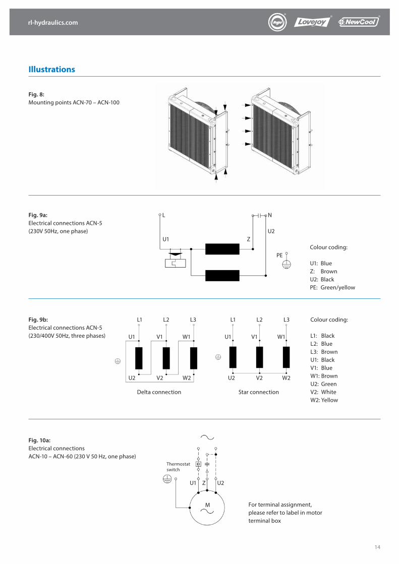
Fig. 8: Mounting points ACN-70 – ACN-100
Fig. 9a: Electrical connections ACN-5 (230V 50Hz, one phase)
Fig. 9b: Electrical connections ACN-5 (230/400V 50Hz, three phases)
Fig. 10a: Electrical connectionsACN-10 – ACN-60 (230 V 50 Hz, one phase)
Colour coding:
U1: BlueZ: BrownU2: BlackPE: Green/yellow
Colour coding: L1: BlackL2: BlueL3: BrownU1: BlackV1: BlueW1: BrownU2: GreenV2: WhiteW2: Yellow
For terminal assignment, please refer to label in motor terminal box
PE
U2
N
ZU1
L
Delta connection
L1 L2 L3
U2 V2 W2
U1 V1 W1
Star connection
L1 L2 L3
U2 V2 W2
U1 V1 W1
Thermostat switch
U1 Z U2
M
Illustrations

rl-hydraulics.com
15
Fig. 10b: Electrical connections ACN-10 – ACN-100 (230/400V 50Hz, three phases)
Fig. 11: Hydraulic connection One-way radiator (ACN-5-1 bis ACN-100-1)
Fig. 12: Hydraulic connection Two-way radiator (ACN-5-2 bis ACN-60-2)
Fig. 13: Measurement ports
Variant a (Standard) Variant b (reduced cooling performance)
Delta connection
W2 U2 V2
U1 V1 W1
L1 L2 L3
Star connection
W2 U2 V2
U1 V1 W1
L1 L2 L3
Illustrations
rl-hydraulics.com
16
Illustrations
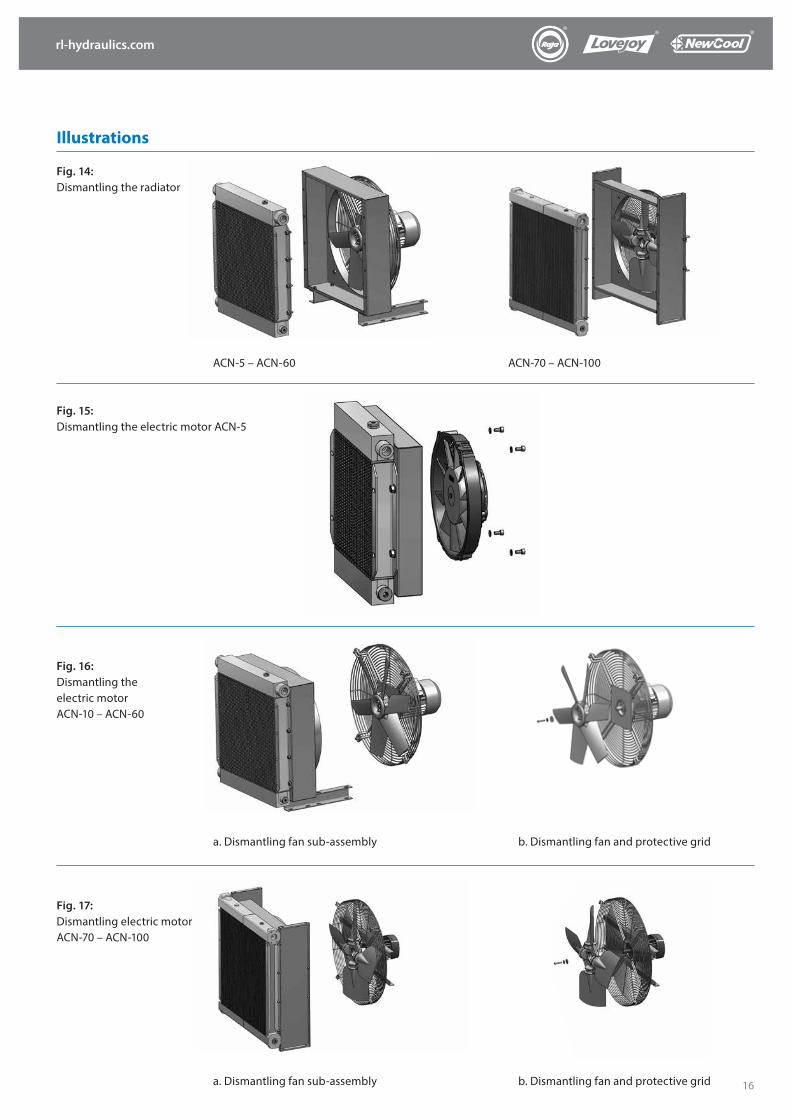
Fig. 15: Dismantling the electric motor ACN-5
Fig. 16: Dismantling the electric motor ACN-10 – ACN-60
b. Dismantling fan and protective grid
Fig. 17: Dismantling electric motor ACN-70 – ACN-100
a. Dismantling fan sub-assembly b. Dismantling fan and protective grid
ACN-5 – ACN-60
Fig. 14: Dismantling the radiator
ACN-70 – ACN-100
a. Dismantling fan sub-assembly
rl-hydraulics.com
17
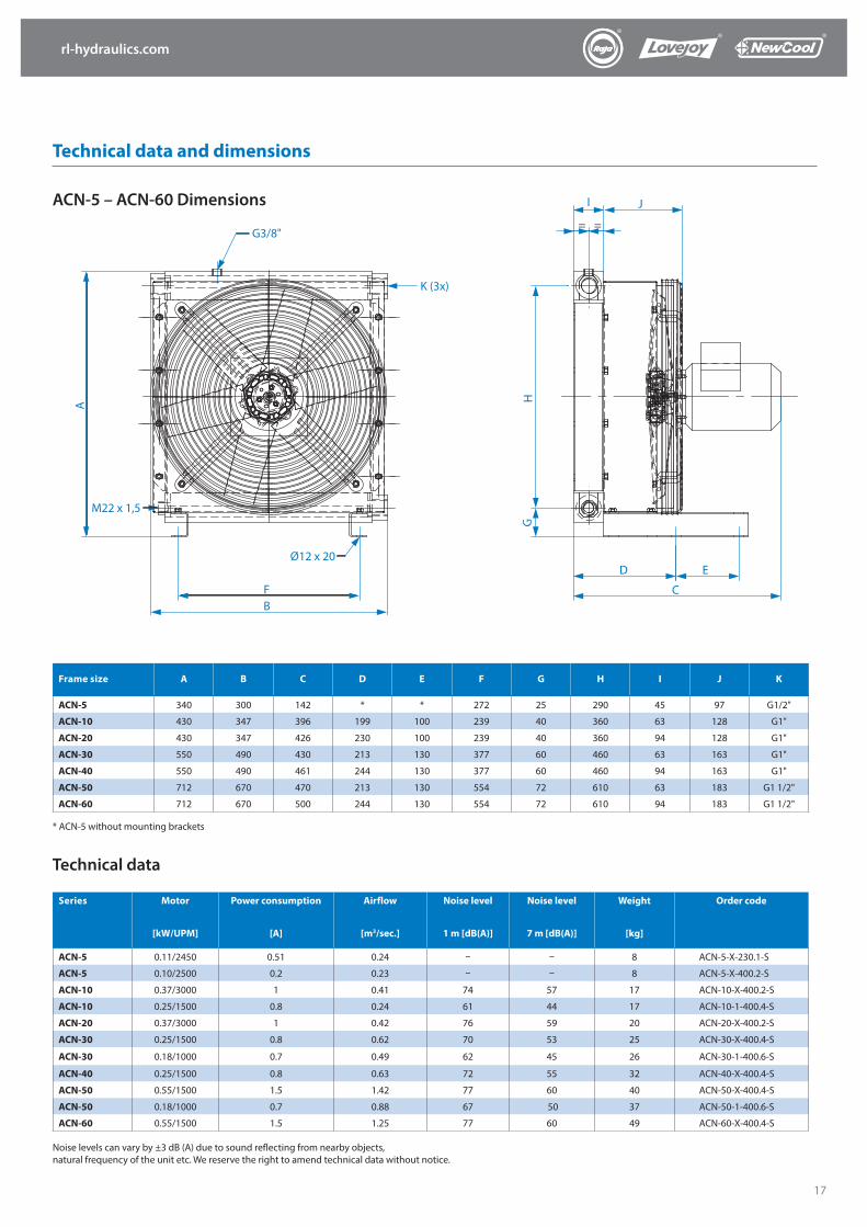
G3/8"
M22 x 1,5
Ø12 x 20
K (3x)
BF
A
I J
= =
D E
C
GH
ACN-5 – ACN-60 Dimensions
Technical data and dimensions
Frame size A B C D E F G H I J K
ACN-5 340 300 142 * * 272 25 290 45 97 G1/2"
ACN-10 430 347 396 199 100 239 40 360 63 128 G1"
ACN-20 430 347 426 230 100 239 40 360 94 128 G1"
ACN-30 550 490 430 213 130 377 60 460 63 163 G1"
ACN-40 550 490 461 244 130 377 60 460 94 163 G1"
ACN-50 712 670 470 213 130 554 72 610 63 183 G1 1/2"
ACN-60 712 670 500 244 130 554 72 610 94 183 G1 1/2"
Series Motor
[kW/UPM]
Power consumption
[A]
Airflow
[m3/sec.]
Noise level
1 m [dB(A)]
Noise level
7 m [dB(A)]
Weight
[kg]
Order code
ACN-5 0.11/2450 0.51 0.24 – – 8 ACN-5-X-230.1-S
ACN-5 0.10/2500 0.2 0.23 – – 8 ACN-5-X-400.2-S
ACN-10 0.37/3000 1 0.41 74 57 17 ACN-10-X-400.2-S
ACN-10 0.25/1500 0.8 0.24 61 44 17 ACN-10-1-400.4-S
ACN-20 0.37/3000 1 0.42 76 59 20 ACN-20-X-400.2-S
ACN-30 0.25/1500 0.8 0.62 70 53 25 ACN-30-X-400.4-S
ACN-30 0.18/1000 0.7 0.49 62 45 26 ACN-30-1-400.6-S
ACN-40 0.25/1500 0.8 0.63 72 55 32 ACN-40-X-400.4-S
ACN-50 0.55/1500 1.5 1.42 77 60 40 ACN-50-X-400.4-S
ACN-50 0.18/1000 0.7 0.88 67 50 37 ACN-50-1-400.6-S
ACN-60 0.55/1500 1.5 1.25 77 60 49 ACN-60-X-400.4-S
Noise levels can vary by ±3 dB (A) due to sound reflecting from nearby objects, natural frequency of the unit etc. We reserve the right to amend technical data without notice.
Technical data
* ACN-5 without mounting brackets
rl-hydraulics.com
18
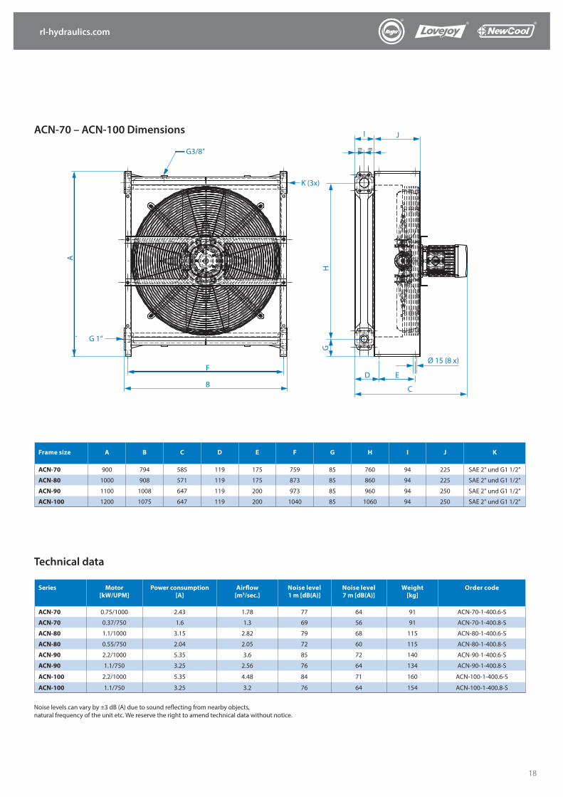
Frame size A B C D E F G H I J K
ACN-70 900 794 585 119 175 759 85 760 94 225 SAE 2" und G1 1/2"
ACN-80 1000 908 571 119 175 873 85 860 94 225 SAE 2" und G1 1/2"
ACN-90 1100 1008 647 119 200 973 85 960 94 250 SAE 2" und G1 1/2"
ACN-100 1200 1075 647 119 200 1040 85 1060 94 250 SAE 2" und G1 1/2"
Series Motor[kW/UPM]
Power consumption[A]
Airflow[m3/sec.]
Noise level1 m [dB(A)]
Noise level7 m [dB(A)]
Weight[kg]
Order code
ACN-70 0.75/1000 2.43 1.78 77 64 91 ACN-70-1-400.6-S
ACN-70 0.37/750 1.6 1.3 69 56 91 ACN-70-1-400.8-S
ACN-80 1.1/1000 3.15 2.82 79 68 115 ACN-80-1-400.6-S
ACN-80 0.55/750 2.04 2.05 72 60 115 ACN-80-1-400.8-S
ACN-90 2.2/1000 5.35 3.6 85 72 140 ACN-90-1-400.6-S
ACN-90 1.1/750 3.25 2.56 76 64 134 ACN-90-1-400.8-S
ACN-100 2.2/1000 5.35 4.48 84 71 160 ACN-100-1-400.6-S
ACN-100 1.1/750 3.25 3.2 76 64 154 ACN-100-1-400.8-S
Noise levels can vary by ±3 dB (A) due to sound reflecting from nearby objects, natural frequency of the unit etc. We reserve the right to amend technical data without notice.
ACN-70 – ACN-100 Dimensions
Technical data
G3/8"
K (3x)
A
G 1“
F
B
GH
I J
= =
Ø 15 (8 x)
D E
C
rl-hydraulics.com
19
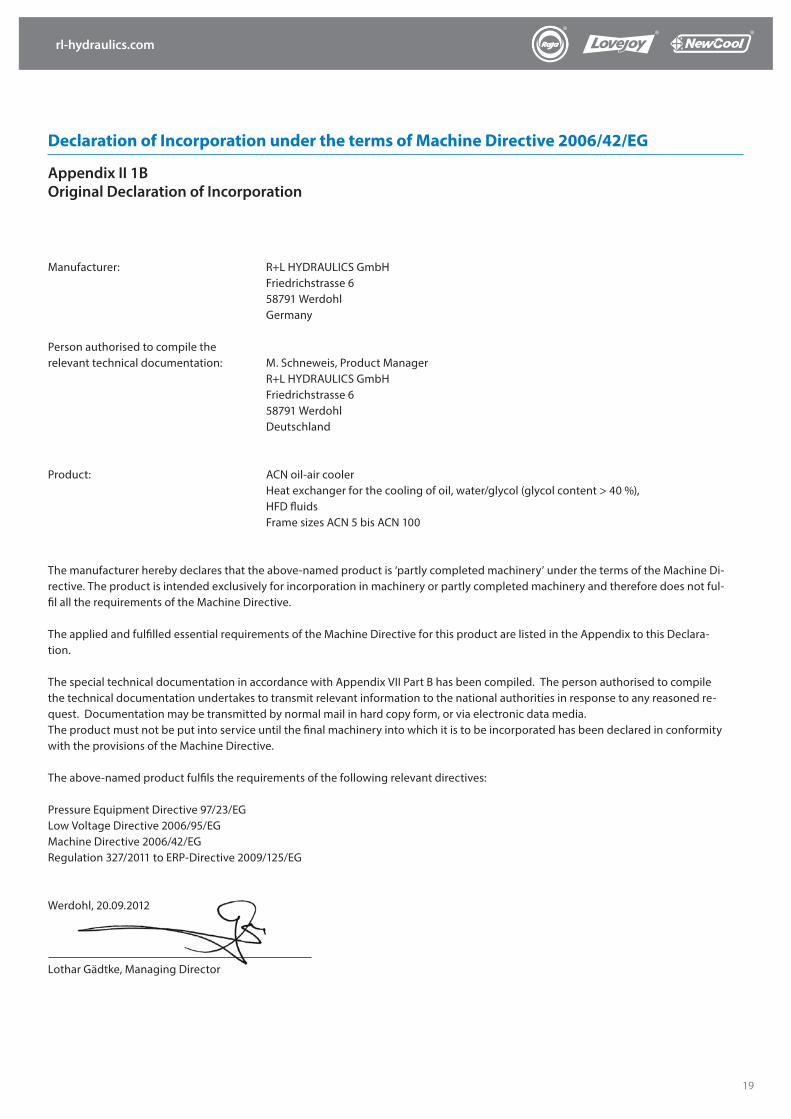
Declaration of Incorporation under the terms of Machine Directive 2006/42/EG
Appendix II 1B Original Declaration of Incorporation
Manufacturer: R+L HYDRAULICS GmbH Friedrichstrasse 6 58791 Werdohl Germany
Person authorised to compile the relevant technical documentation: M. Schneweis, Product Manager R+L HYDRAULICS GmbH Friedrichstrasse 6 58791 Werdohl Deutschland
Product: ACN oil-air cooler Heat exchanger for the cooling of oil, water/glycol (glycol content > 40 %), HFD fluids Frame sizes ACN 5 bis ACN 100
The manufacturer hereby declares that the above-named product is ‘partly completed machinery’ under the terms of the Machine Di-rective. The product is intended exclusively for incorporation in machinery or partly completed machinery and therefore does not ful-fil all the requirements of the Machine Directive.
The applied and fulfilled essential requirements of the Machine Directive for this product are listed in the Appendix to this Declara-tion.
The special technical documentation in accordance with Appendix VII Part B has been compiled. The person authorised to compile the technical documentation undertakes to transmit relevant information to the national authorities in response to any reasoned re-quest. Documentation may be transmitted by normal mail in hard copy form, or via electronic data media.The product must not be put into service until the final machinery into which it is to be incorporated has been declared in conformity with the provisions of the Machine Directive. The above-named product fulfils the requirements of the following relevant directives:
Pressure Equipment Directive 97/23/EGLow Voltage Directive 2006/95/EGMachine Directive 2006/42/EGRegulation 327/2011 to ERP-Directive 2009/125/EG
Werdohl, 20.09.2012
Lothar Gädtke, Managing Director
rl-hydraulics.com
20
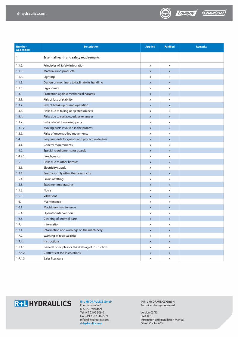
Number Appendix I
Description Applied Fulfilled Remarks
1. Essential health and safety requirements
1.1.2. Principles of Safety Integration x x
1.1.3. Materials and products x x
1.1.4. Lighting x x
1.1.5. Design of machinery to facilitate its handling x x
1.1.6. Ergonomics x x
1.3. Protection against mechanical hazards x x
1.3.1. Risk of loss of stability x x
1.3.2. Risk of break-up during operation x x
1.3.3. Risks due to falling or ejected objects x x
1.3.4. Risks due to surfaces, edges or angles x x
1.3.7. Risks related to moving parts x x
1.3.8.2. Moving parts involved in the process x x
1.3.9. Risks of uncontrolled movements x x
1.4. Requirements for guards and protective devices x x
1.4.1. General requirements x x
1.4.2. Special requirements for guards x x
1.4.2.1. Fixed guards x x
1.5. Risks due to other hazards x x
1.5.1. Electricity supply x x
1.5.3. Energy supply other than electricity x x
1.5.4. Errors of fitting x x
1.5.5. Extreme temperatures x x
1.5.8. Noise x x
1.5.9. Vibrations x x
1.6. Maintenance x x
1.6.1. Machinery maintenance x x
1.6.4. Operator intervention x x
1.6.5. Cleaning of internal parts x x
1.7. Information x x
1.7.1. Information and warnings on the machinery x x
1.7.2. Warning of residual risks x x
1.7.4. Instructions x x
1.7.4.1. General principles for the drafting of instructions x x
1.7.4.2. Contents of the instructions x x
1.7.4.3. Sales literature x x
R+L HYDRAULICS GmbH Friedrichstraße 6D-58791 Werdohl Tel +49 2392 509-0Fax +49 2392 [email protected]
© R+L HYDRAULICS GmbH Technical changes reserved
Version 03/13BMA 0010Instruction and Installation Manual Oil-Air Cooler ACN