instituto brasileiro de petróleo, gás e biocombustíveis · 20160803/atmm · evolution in control...
TRANSCRIPT
20160803/atmm · Evolution in control valves for severe services · 1
Dr. Ing. Alberto Tamm Reiners
SAMSON AGTitle:
Evolution in control valves for severe services
Instituto Brasileiro de Petróleo, Gás e Biocombustíveis
Dr. Alberto Tamm, SAMSON CONTROL LTDA.

20160803/atmm · Evolution in control valves for severe services · 2
Reliability Performance Criteria—Severe service conditions are
those which impact the valve's reliability. Severe service conditions
include the following:
Cavitation or flashing
High pressure drop, where the pressure drop exceeds the critical pressure
Cavitating services, where more than a two stage let-down trim is
required to meet the noise limits without application of path treatment
Flashing services with downstream vapor content exceeding 10% weight
Two-phase flow services with downstream vapor content exceeding 10% weight
High piping vibration
Erosion, such as solids in the fluid, liquid particles in gas stream, and stream.
High valve outlet velocity (liquids > 5 m/sec; gas/steam > 0.3 mach,
Two phase flow, flashing > 60m/s (196 ft/s)
High Performance Control Valves lean on statements of major oil companies and valve suppliers
Topic of Valve World
Converence Dec. 2005

20160803/atmm · Evolution in control valves for severe services · 3
High Performance Control Valves
“Key” valves
This are valves with highest responsibility for production
targets like quality and quantity as well as plant safety and
economics.
Crude oil supply valves
Pump – and flow machine protection valves
Flare- valves
Feed water, cooling water and fire fighting valves.
Start up (process balance), shut down valves
Valves with
high dynamic actions
high anti-corrosion features
high anti-abrasion features
high demand on control quality (controllability)
(e.g. insulin production, )
Valves with unique design features and high replacement cost
2011

20160803/atmm · Evolution in control valves for severe services · 4
Severe service operating conditions
• Cavitation noise with sound pressure levels between 90 and 100 dB(A)
• Critical cavitation -> damage (plug, seat, body, pipe)
• Flashing -> damage (erosion) (plug, seat, body, pipe)
• Two phase medium at the valve inlet -> damage (erosion)
• Damage can be caused by:
• Mechanical Sources
• Hydrodynamic Sources
• Erosive and Corrosive Service
Severe service definitions (liquid applications)

20160803/atmm · Evolution in control valves for severe services · 5
4) Ideal gas/air
3) Overheated vapor/steam
2) Saturated vapor/steam
1) Wet vapor/steam
Cavitation and flashing convert liquid
to Wet vapor/steam
with the highest potential of damage !
Ranking list of damage potential :
Vapor velocity
Liquid velocity
Average velocity
Cavitation: Water, 20°Cp1 = 6 bar, p2 = 2 bar
Damage potential in case of cavitation and flashing
20160803/atmm · Evolution in control valves for severe services · 6
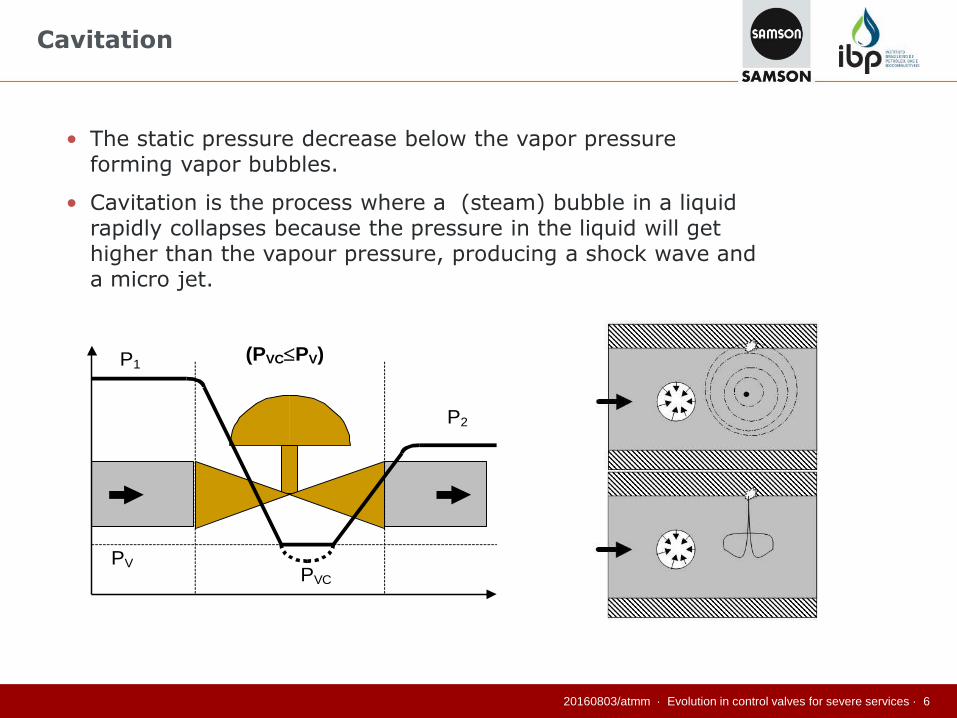
Cavitation
• The static pressure decrease below the vapor pressure forming vapor bubbles.
• Cavitation is the process where a (steam) bubble in a liquid rapidly collapses because the pressure in the liquid will get higher than the vapour pressure, producing a shock wave and a micro jet.
(PVCPV)P1
P2
PVPVC
20160803/atmm · Evolution in control valves for severe services · 7
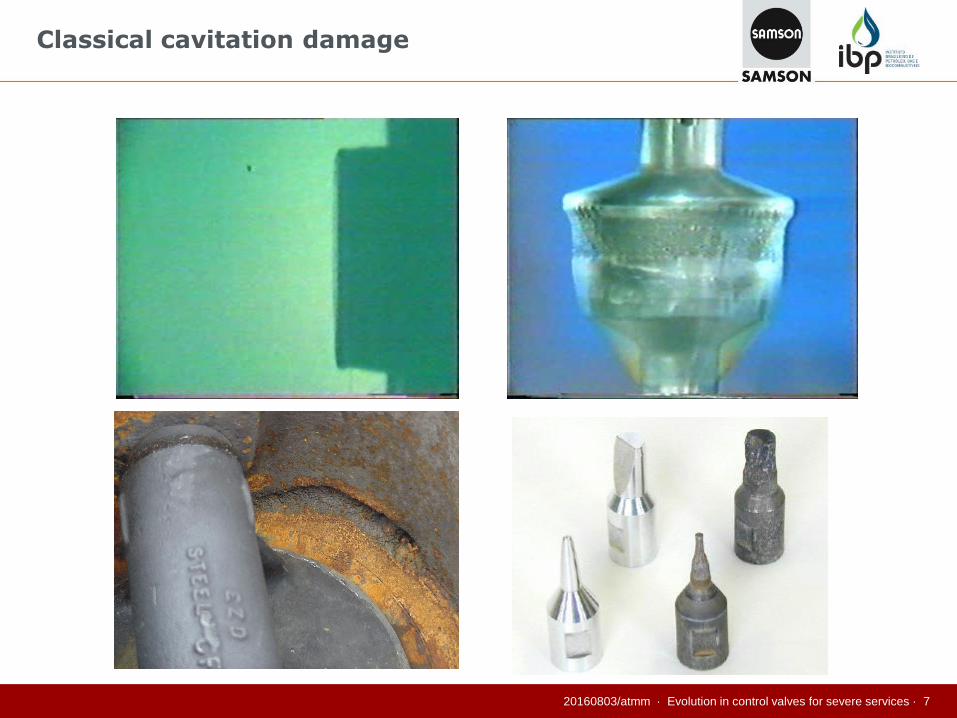
Classical cavitation damage

20160803/atmm · Evolution in control valves for severe services · 8
Flow measurement (liquid)

20160803/atmm · Evolution in control valves for severe services · 9
Sound measurements IEC 534 8-4
3" Globe Valve (Cv 30) , Water p1=8 bar(a), pv=2 bar
40
45
50
55
60
65
70
75
80
0 0.1 0.2 0.3 0.4 0.5 0.6 0.7 0.8 0.9 1 1.1 1.2
xF
Lp
Ae
Flow measurements IEC 534 2-1
1/sch FL (xFch)1/sid Kc FL³ (xFid)Approx. 1/si xFz (xFi)
ISA RP 75.23
xFz
Kc
FL
Cavitation sound level

20160803/atmm · Evolution in control valves for severe services · 10
0.000 0.005 0.010 0.015 0.020 0.025 0.030
0.00
0.05
0.10
0.15
0.20
-0.05
-0.10
-0.15
-0.20
V-Port-plug
Parabolic plug
Time [s]
Damage due to vibration behaviour V-Port- und Parabolic plug
V-Port-Plug Parabolic-Plug
Vibration sensors Parabolic plug• symmetric• outlet through ring gap
V-Port-plug• asymmetric• defined outlet

20160803/atmm · Evolution in control valves for severe services · 11
velocity profiles
Solutions in case of severe cavitation
Optimization of the plug and seat geometry toreduce cavitation noise (increase of xFz-value)
20160803/atmm · Evolution in control valves for severe services · 12
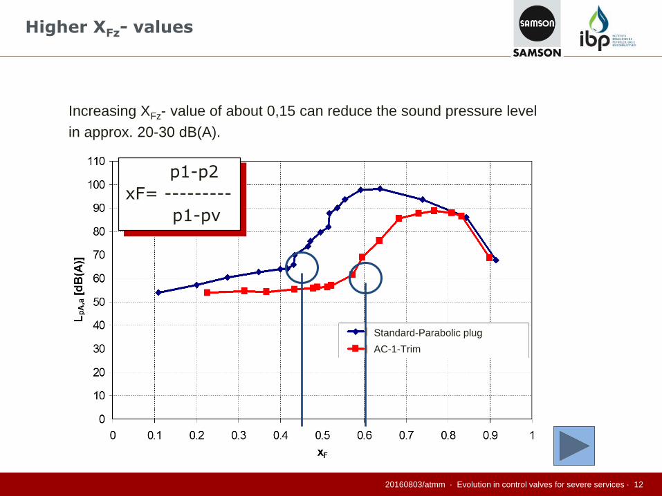
Increasing XFz- value of about 0,15 can reduce the sound pressure level
in approx. 20-30 dB(A).
Standard-Parabolic plug
AC-1-Trim
p1-p2
xF= ---------
p1-pv
Higher XFz- values

20160803/atmm · Evolution in control valves for severe services · 13
CFD optimization pressure reduction in steps
Solutions in case of severe cavitation

20160803/atmm · Evolution in control valves for severe services · 14
Globe valve
type
XFz for valve
75% load
XFz for valve
<< 75% load
Resistance to con-
tamination
Vibration be-
havior
Parabolic plug 0.25 to 0.35 clearly up to
0.8
high poor for single-
guided plugs
Piston-balanced
plug with cage
0.25 to 0.35 up to 0.5 low good
V-port plug 0.25 to 0.35 up to 0.5 high excellent
Perforated plug 0.25 to 0.35 0.25 to 0.35 low good
AC Trim
System
0.35 to 0.5 clearly up to
0.85
high good
AC 1 AC 2 AC 3 AC 5
Max p = 25 bar Max p = 100 bar Max p = 200 bar
Anti cavitation trims
20160803/atmm · Evolution in control valves for severe services · 15
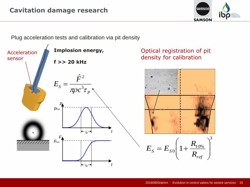
P
Sc
FE
3
2ˆ
pmax
p
tP
Fmax
F
tP
Implosion energy,
f >> 20 kHz
Acceleration sensor
3
%100 1
ref
SSR
REE
Optical registration of pit density for calibration
Plug acceleration tests and calibration via pit density
Cavitation damage research

20160803/atmm · Evolution in control valves for severe services · 16
Cavitation damage researchxFid via acceleration measurement inside plug
cavitation
with
erosion
no cavitation
xFz
cavitation
without
erosion
xFmr

20160803/atmm · Evolution in control valves for severe services · 17
1 2 3 4
1: Dp = 33.4 bar, p1 = 35.2 bar2: Dp = 66.8 bar, p1 = 70.3 bar3: Dp = 101.6 bar, p1 = 105.5 bar4: Dp = 133.6 bar, p1 = 140.6 bar
• diameter 150 m • jet velocity 400 km/h • 5500 º C
Cavitation intensity
• higher for xF->Kc (more bubbles)• higher with p (kinetic energy)• critical p
Cavitation damage in globe valves
Cavitation damage research

20160803/atmm · Evolution in control valves for severe services · 18
Flashing test rig in SAMSON’s development center
Problem:
• Volume and velocity increase in the mixture during the expansion
• The mixture has, in comparison to each single component, a lower sonic velocity
A wrong selection rapidly leads to unstable flow characteristics with high vibration and mechanical loading.

20160803/atmm · Evolution in control valves for severe services · 19
In case of flashing, wet vapor can reach sonic velocity.
Recommended max. trim outlet velocity about 60 m/s (200 ft/s) with choked flow.
Flashing liquids, or liquid-vapor mixtures have significantly lower sonic velocities than each single phase.
The mixture has, in comparison toeach single component, a lower sonic velocity
Sonic velocity
water-water vapor mixtures
0
200
400
600
800
1000
1200
0 0,2 0,4 0,6 0,8 1
volumen fraction,
so
nic
velo
cit
y,
a [
m/s
]
0
0,2
0,4
0,6
0,8
1
1,2
ma
ss
fra
cti
on
l, x
[ -
]
60
275,6
1149 574
p0 = bar, saturated
Temp = °C
m/s m/s
20160803/atmm · Evolution in control valves for severe services · 20
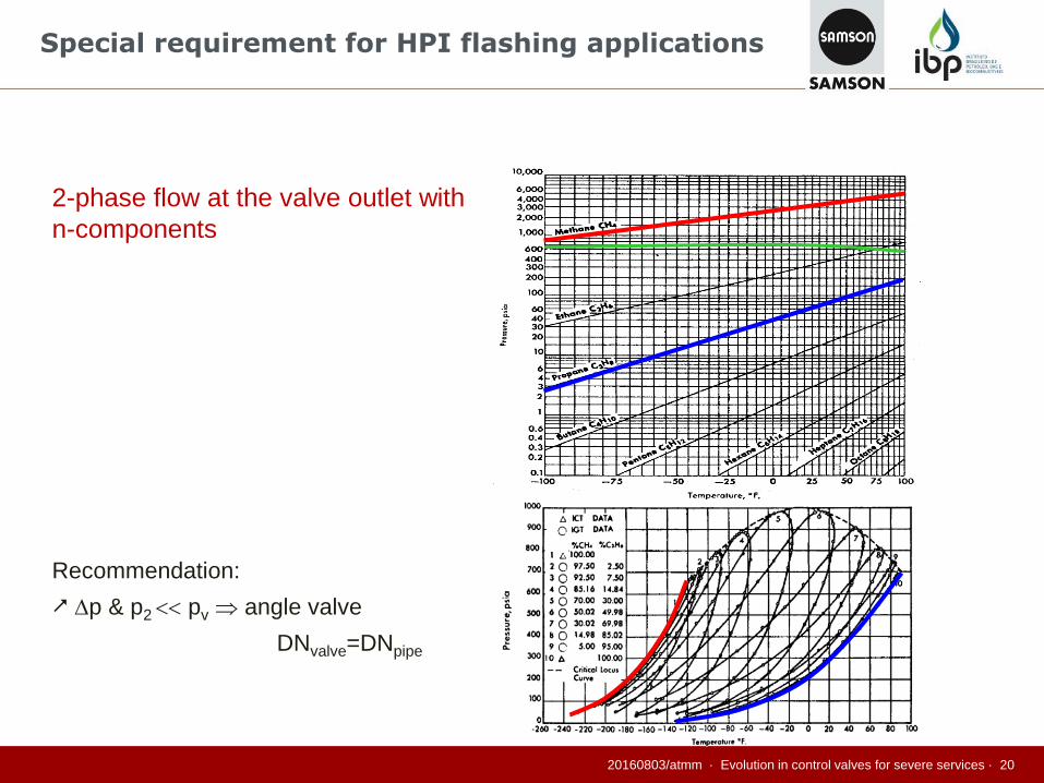
2-phase flow at the valve outlet with
n-components
Recommendation:
p & p2 pv angle valve
DNvalve=DNpipe
Special requirement for HPI flashing applications

20160803/atmm · Evolution in control valves for severe services · 21
0
40
30
20
10
5
15
25
35
Single stage valves with reduced seat size to provide as much space as possible to the flow at the valve outlet show a continuous and erosion free operating behaviour.
The seat guided V-port plug avoids flow vibration and resonance oscillations through it strong guiding and asymmetrical form.
DN3” 16 m/s DN6” 4.8 m/s
In the case of flashing critical valveoutlet velocities needs attention

20160803/atmm · Evolution in control valves for severe services · 22
Liquids:p < pcrit._cav. = 25 bar (Globe valves, single stage plug)• < 5 m/s, if partial cavitation occurs: xFz < xF < Kc;
• < 3 m/s, if severe cavitation occurs: xF > Kc,
p > pcrit._cav. = 25 bar (Globe valves, multi stage plug)
• < 3 m/s, if cavitation occurs: xF > xFz,
Corrosive liquids like acids:• avoid cavitation: xF < xFz
if no risk of cavitation v < 6 m/s
General for non corrosive fluids, free of cavitation PN <= class 600 v < 8 m/s if flashing* occurs: xF > 1; v < 60m/s
Gas and Steam, Vapors:
• < 0,3 Mach, general, but important with low noise devices
• 0,3 < Ma < 0,6 , short operation time*see publication: Dr. Kiesbauer and Samson-Valve Sizing
Long term reliability recommendations

20160803/atmm · Evolution in control valves for severe services · 23
Even if the single process seems to be simple, a modern refinery is a complexprocess plant, which requires a specific know-how.
An Overview ....

20160803/atmm · Evolution in control valves for severe services · 24
Simplified HPI Units
valve A
valve B
valve C

20160803/atmm · Evolution in control valves for severe services · 25
Valve specification sheets are often from low quality: operating points are missing or not logical sorted to qmax, qnorm, qmin.
Important property data, worst case conditions like start up conditions, control loop information, ”identification of key valves” - etc. are missing.
The specification volume including increasing paperwork of standards, special regulations, and tailored customer requirements have more than doubled.
Time for huge project offers is more than halved.
Detail engineering-sources for plant-and valve designers dried out !
20160803/atmm · Evolution in control valves for severe services · 26
Plant- and valve designers need time to select control valves, sound level and economic aspects. Serious control valve selection requires detail engineering with competence.
Control valve engineers need long-term experience and high skills in measurement and control, mechanical engineering and thermodynamics.
No time for detail engineering will increase the risk of “quick and dirty” sizing.
Detail engineering-sources for plant-and valve designers dried out !

20160803/atmm · Evolution in control valves for severe services · 27
This slide shows some work done on control valve Total Cost of Ownership by a team from Heritage Amoco
Spend profile over lifetime Cost element1998
% of TCO
Purchase Price 12.0
Procurement 0.9
Engineering 8.9
Installation Cost 5.3
Maintenance 65.0
Spares 5.3
Utilities 2.5
Total Cost of Ownership TCO
• 13% of the cost of the valve is related to the initial purchase,• 14% relates to the engineering and installation and the remainder,• 73% relates to the maintenance and the ongoing valve operations.

20160803/atmm · Evolution in control valves for severe services · 28
Dow Chemical Presentation
(Valve World Conference 2004)
Total cost of ownership

20160803/atmm · Evolution in control valves for severe services · 29
Life Cycle Costs for BASF
(approx. 50,000 Samson Control Valves)
TCO comparison

20160803/atmm · Evolution in control valves for severe services · 30
Users of competitors valves
Purchase Price Maintenance
DOW 100% 567%
AMOCO 100% 450%
SAMSON User
BASF – 50,000 Valves
Standard Applications 100% 30%
Severe Service 100% 200%
Maintenance and repairs costs vs. initial purchase price
TCO comparison

20160803/atmm · Evolution in control valves for severe services · 31
Muito obrigado pela sua atenção