installing the fuse box - american autowire 510190 in 0.0.pdf · following these simple...
TRANSCRIPT
510190 DASH KIT
92969483 instruction rev 0.0 10/28/2010
1964-1967 GTO Gbag
10A
10A
10A
15A
5A
15A
30A
30A20A 20A
30A
30A
30A
10A
10A10A
10A
15A
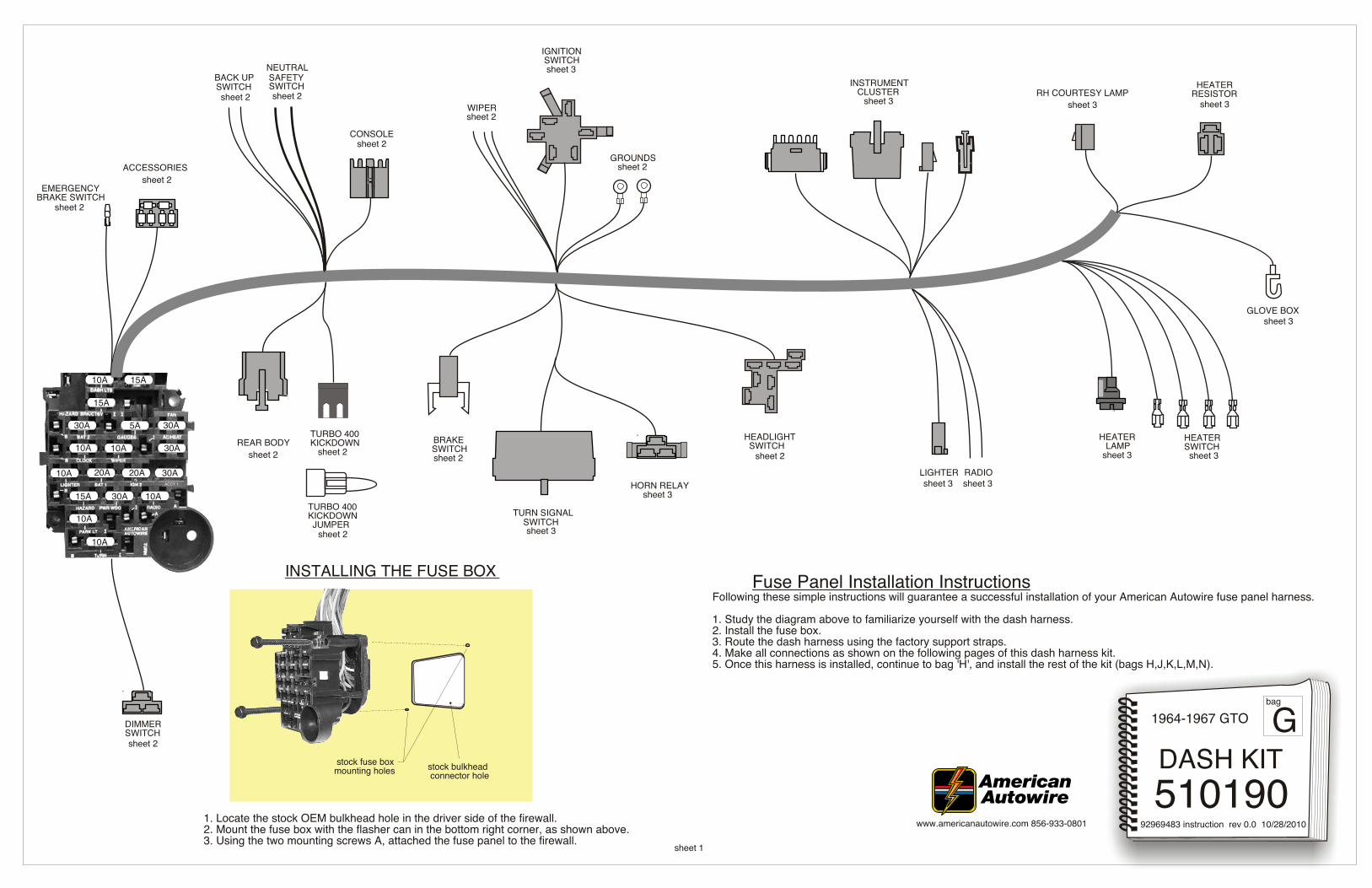
Fuse Panel Installation InstructionsFollowing these simple instructions will guarantee a successful installation of your American Autowire fuse panel harness.
1. Study the diagram above to familiarize yourself with the dash harness.2. Install the fuse box.3. Route the dash harness using the factory support straps.4. Make all connections as shown on the following pages of this dash harness kit.5. Once this harness is installed, continue to bag 'H', and install the rest of the kit (bags H,J,K,L,M,N).
EMERGENCYBRAKE SWITCH
ACCESSORIES
INSTRUMENT CLUSTER
REAR BODY
WIPER
HEADLIGHT SWITCH
TURN SIGNALSWITCH
HORN RELAY
BRAKESWITCH
LIGHTER
RH COURTESY LAMP HEATER RESISTOR
HEATER SWITCH
GLOVE BOX
IGNITION SWITCH
BACK UPNEUTRAL
SWITCH
RADIO
sheet 1
sheet 2
DIMMERSWITCHsheet 2
sheet 2
sheet 2
GROUNDSsheet 2
sheet 2
sheet 3
sheet 3sheet 3sheet 3
sheet 3 sheet 3
sheet 3
sheet 3
sheet 3
sheet 2 sheet 2
sheet 2
sheet 2
sheet 2
sheet 3
ACCY 1
K J
H
stock fuse boxmounting holes stock bulkhead
connector hole
INSTALLING THE FUSE BOX
1. Locate the stock OEM bulkhead hole in the driver side of the firewall.2. Mount the fuse box with the flasher can in the bottom right corner, as shown above.3. Using the two mounting screws A, attached the fuse panel to the firewall.
HEATER LAMP
sheet 3
CONSOLEsheet 2
www.americanautowire.com 856-933-0801
SWITCHSAFETY
D ABC
TURBO 400KICKDOWN
TURBO 400KICKDOWN
JUMPER
sheet 2
fuse box
3
sheet 2
C
C
C
C
C
C
C
C
C
C
64 Single Speed with washer
67 GTO, LeMans, Tempest All
65-66 GTO, LeMans, Tempest All
64 2 Speed with washer
*dark blue and black not used
lt bluedk blue
black
lt blue
dk blue
lt blue
black
510190 DASH KIT
1964-1967 GTO
92969483 instruction rev 0.0 10/28/2010www.americanautowire.com 856-933-0801
dk blue
lt blue
black
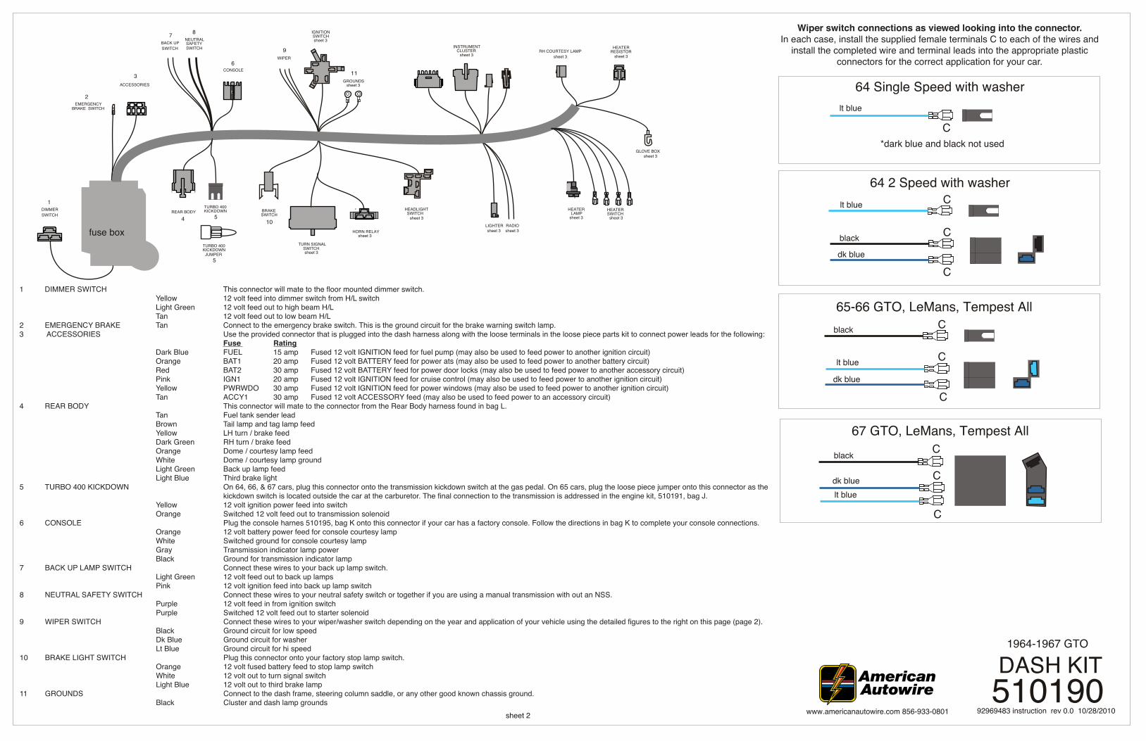
Wiper switch connections as viewed looking into the connector. In each case, install the supplied female terminals C to each of the wires and
install the completed wire and terminal leads into the appropriate plastic connectors for the correct application for your car.
INSTRUMENT CLUSTER
REAR BODY
WIPER
HEADLIGHT SWITCH
TURN SIGNALSWITCH
HORN RELAY
BRAKESWITCH
LIGHTER
RH COURTESY LAMP HEATER RESISTOR
HEATER SWITCH
GLOVE BOX
IGNITION SWITCH
BACK UPNEUTRAL
SWITCH
RADIO4
GROUNDSsheet 3
sheet 3
sheet 3
sheet 3sheet 3sheet 3
sheet 3 sheet 3
sheet 3
sheet 3
sheet 37 8
9
10
11
1
sheet 3
K J
H
HEATER LAMP
sheet 3
CONSOLE6
SWITCHSAFETY
D ABC
TURBO 400KICKDOWN
5
TURBO 400KICKDOWN
JUMPER5
ACCESSORIES
DIMMER SWITCH
2EMERGENCY
BRAKE SWITCH
1 DIMMER SWITCH This connector will mate to the floor mounted dimmer switch. Yellow 12 volt feed into dimmer switch from H/L switch Light Green 12 volt feed out to high beam H/L Tan 12 volt feed out to low beam H/L2 EMERGENCY BRAKE Tan Connect to the emergency brake switch. This is the ground circuit for the brake warning switch lamp.3 ACCESSORIES Use the provided connector that is plugged into the dash harness along with the loose terminals in the loose piece parts kit to connect power leads for the following: Fuse Rating Dark Blue FUEL 15 amp Fused 12 volt IGNITION feed for fuel pump (may also be used to feed power to another ignition circuit) Orange BAT1 20 amp Fused 12 volt BATTERY feed for power ats (may also be used to feed power to another battery circuit) Red BAT2 30 amp Fused 12 volt BATTERY feed for power door locks (may also be used to feed power to another accessory circuit) Pink IGN1 20 amp Fused 12 volt IGNITION feed for cruise control (may also be used to feed power to another ignition circuit) Yellow PWRWDO 30 amp Fused 12 volt IGNITION feed for power windows (may also be used to feed power to another ignition circuit) Tan ACCY1 30 amp Fused 12 volt ACCESSORY feed (may also be used to feed power to an accessory circuit)4 REAR BODY This connector will mate to the connector from the Rear Body harness found in bag L. Tan Fuel tank sender lead Brown Tail lamp and tag lamp feed Yellow LH turn / brake feed Dark Green RH turn / brake feed Orange Dome / courtesy lamp feed White Dome / courtesy lamp ground Light Green Back up lamp feed Light Blue Third brake light5 TURBO 400 KICKDOWN On 64, 66, & 67 cars, plug this connector onto the transmission kickdown switch at the gas pedal. On 65 cars, plug the loose piece jumper onto this connector as the kickdown switch is located outside the car at the carburetor. The final connection to the transmission is addressed in the engine kit, 510191, bag J. Yellow 12 volt ignition power feed into switch Orange Switched 12 volt feed out to transmission solenoid 6 CONSOLE Plug the console harnes 510195, bag K onto this connector if your car has a factory console. Follow the directions in bag K to complete your console connections. Orange 12 volt battery power feed for console courtesy lamp White Switched ground for console courtesy lamp Gray Transmission indicator lamp power Black Ground for transmission indicator lamp7 BACK UP LAMP SWITCH Connect these wires to your back up lamp switch. Light Green 12 volt feed out to back up lamps Pink 12 volt ignition feed into back up lamp switch8 NEUTRAL SAFETY SWITCH Connect these wires to your neutral safety switch or together if you are using a manual transmission with out an NSS. Purple 12 volt feed in from ignition switch Purple Switched 12 volt feed out to starter solenoid9 WIPER SWITCH Connect these wires to your wiper/washer switch depending on the year and application of your vehicle using the detailed figures to the right on this page (page 2). Black Ground circuit for low speed Dk Blue Ground circuit for washer Lt Blue Ground circuit for hi speed10 BRAKE LIGHT SWITCH Plug this connector onto your factory stop lamp switch. Orange 12 volt fused battery feed to stop lamp switch White 12 volt out to turn signal switch Light Blue 12 volt out to third brake lamp11 GROUNDS Connect to the dash frame, steering column saddle, or any other good known chassis ground. Black Cluster and dash lamp grounds
fuse box
510190 DASH KIT
1964-1967 GTO
sheet 3
92969483 instruction rev 0.0 10/28/2010www.americanautowire.com 856-933-0801
whitedk greenyellowpurplebrowndk bluelt blueblack
whitedk greenyellowpurple
lt blueblack
dk bluebrown (67 only)
ORIGINAL TURN SIGNAL SWITCH WIRESAMERICAN AUTOWIRE
DASH HARNESS CONNECTION
M
M
L
L
INSTRUMENT CLUSTER
REAR BODY
WIPER
HEADLIGHT SWITCH
TURN SIGNALSWITCH
HORN RELAY
BRAKESWITCH
LIGHTER
RH COURTESY LAMP HEATER RESISTOR
HEATER SWITCH
GLOVE BOX
IGNITION SWITCHBACK UP
NEUTRAL
SWITCH
RADIO
sheet 2
sheet 2
GROUNDSsheet 2
sheet 3 sheet 3
sheet 2
sheet 2
K J
H
HEATER LAMP
CONSOLEsheet 2
SWITCHSAFETY
D ABC
TURBO 400KICKDOWN
sheet 2
sheet 2
1
2
sheet 2
EMERGENCY
sheet 2 BRAKE SWITCH
ACCESSORIES
sheet 2
DIMMER SWITCH
TURBO 400KICKDOWN
JUMPER
12
13
14
15
16
17 18
19 23
20 21
22
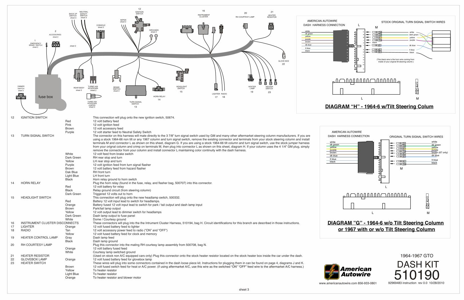
12 IGNITION SWITCH This connection will plug onto the new ignition switch, 50674. Red 12 volt battery feed Pink 12 volt ignition feed Brown 12 volt accessory feed Purple 12 volt starter feed to Neutral Safety Switch13 TURN SIGNAL SWITCH The connector on this harness will mate directly to the 3 7/8” turn signal switch used by GM and many other aftermarket steering column manufacturers. If you are using a stock 1964-66 non tilt or any 1967 column and turn signal switch, remove the existing connector and terminals from your stock steering column and install terminals M and connector L as shown on this sheet, diagram G. If you are using a stock 1964-66 tilt column and turn signal switch, use the stock jumper harness from your orignal column and crimp on terminals M, then plug into connector L as shown on this sheet, diagram H. If your column uses the 4 1/4” GM plug, simply remove the connector from your column and install connector L maintaining color continuity with the dash harness. White 12 volt feed from brake switch Dark Green RH rear stop and turn Yellow LH rear stop and turn Purple 12 volt ignition feed from turn signal flasher Brown 12 volt battery feed from hazard flasher Dak Blue RH front turn Light Blue LH front turn Black Horn relay ground to horn switch14 HORN RELAY Plug the horn relay (found in the fuse, relay, and flasher bag, 500707) into this connector. Red 12 volt battery for relay Black Relay ground circuit (from steering column) Dark Green Triggered 12 volts out to horn15 HEADLIGHT SWITCH This connection will plug onto the new headlamp switch, 500332. Red Battery 12 volt input lead to switch for headlamps. Orange Battery fused 12 volt input lead to switch for park / tail output and dash lamp input Brown Park/tail lamp output Yellow 12 volt output lead to dimmer switch for headlamps Dark Green Dash lamp output to fuse panel White Dome / Courtesy ground16 INSTRUMENT CLUSTER DISCONNECTS These connectors will plug into the the Intrument Cluster Harness, 510194, bag H. Circuit identifications for this branch are described in those instructions.17 LIGHTER Orange 12 volt fused battery feed to lighter18 RADIO Tan 12 volt accessory power feed to radio (”ON” and “OFF”) Yellow 12 volt fused battery feed for clock and memory19 HEATER CONTROL LAMP Gray Dash lamp feed Black Dash lamp ground20 RH COURTESY LAMP Plug this connector into the mating RH courtesy lamp assembly from 500708, bag N. Orange 12 volt battery fused feed White Courtesy lamp switched ground21 HEATER RESISTOR (Used on stock non A/C equipped cars only) Plug this connector onto the stock heater resistor located on the stock heater box inside the car under the dash.22 GLOVEBOX LAMP Orange 12 volt fused battery feed for glovebox lamp23 HEATER SWITCH These wires will plug into some connectors contained in the dash loose piece kit. Instructions for plugging them in can be found on page 4, diagrams J and K. Brown 12 volt fused switch feed for heat or A/C power. (if using aftermarket A/C, use this wire as the switched “ON” “OFF” feed wire to the aftermarket A/C harness.) Yellow To heater resistor Light Blue To heater resistor Orange To heater resistor and blower motor
whitedk greenyellowpurplebrowndk blue
lt blueblack
black
(This black wire is the horn wire coming from inside of your original tilt steering column.)
blank
STOCK ORIGINAL TURN SIGNAL SWITCH WIRESAMERICAN AUTOWIRE DASH HARNESS CONNECTION
ML
DIAGRAM “H” - 1964-6 w/Tilt Steering Colum
A
B
C
D
E
F
G
H
J
K
L
M
N
P
P N M
L K J H G
F E D
white
purple
dark greenyellow
lt blue
dk blue
or 1967 with or w/o Tilt Steering ColumnDIAGRAM ”G” - 1964-6 w/o Tilt Steering Column
ML
sheet 4
510190 DASH KIT
1964-1967 GTO
92969483 instruction rev 0.0 10/28/2010www.americanautowire.com 856-933-0801
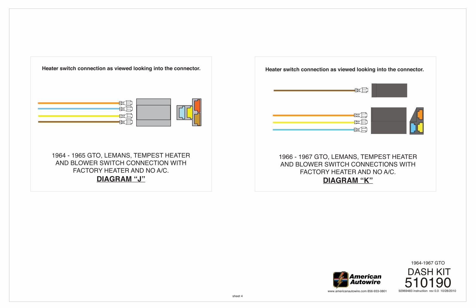
1966 - 1967 GTO, LEMANS, TEMPEST HEATER AND BLOWER SWITCH CONNECTIONS WITH
FACTORY HEATER AND NO A/C.DIAGRAM “K”
1964 - 1965 GTO, LEMANS, TEMPEST HEATER AND BLOWER SWITCH CONNECTION WITH
FACTORY HEATER AND NO A/C.DIAGRAM “J”
Heater switch connection as viewed looking into the connector. Heater switch connection as viewed looking into the connector.