installer manual - nibeiframe.nibenl.eu/docs/231758-2.pdf · designations according to standards...
TRANSCRIPT
Installer manual
LEK
SMO 20Control module
IHB GB 1325-2231758
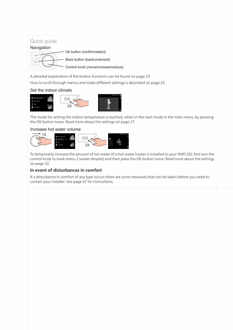
A detailed explanation of the button functions can be found on page 23.
How to scroll through menus and make different settings is described on page 25.
The mode for setting the indoor temperature is reached, when in the start mode in the main menu, by pressingthe OK button twice. Read more about the settings on page 27.
To temporarily increase the amount of hot water (if a hot water heater is installed to your SMO 20), first turn thecontrol knob to mark menu 2 (water droplet) and then press the OK button twice. Read more about the settingson page 32.
In event of disturbances in comfort
If a disturbance in comfort of any type occurs there are some measures that can be taken before you need tocontact your installer. See page 47 for instructions.
Table of Contents1 Important information 2
Safety information 2
2 Delivery and handling 5Mounting 5
Supplied components 5
3 The Control Module Design 6Electrical components 6
4 Pipe connections 7General 7
Docking alternatives 8
5 Electrical connections 11General 11
Connections 14
Optional connections 16
Connecting accessories 20
6 Commissioning and adjusting 21Preparations 21
Commissioning with NIBE air/water heatpump 21
Commissioning with additional heatingonly 21
Check the reversing valve 21
Start guide 22
7 Control - Introduction 23Display unit 23
Menu system 24
8 Control - Menus 27Menu 1 - INDOOR CLIMATE 27
Menu 2 - HOT WATER 32
Menu 3 - INFO 34
Menu 4 - MY SYSTEM 35
Menu 5 - SERVICE 39
9 Service 44Service actions 44
10 Disturbances in comfort 47Manage alarm 47
Troubleshooting 47
Additional heating only 48
11 Accessories 49
12 Technical data 51Dimensions and setting-out coordinates 51
Technical specifications 52
Electrical circuit diagram 53
Item register 57
1Table of Contents |SMO 20
Safety informationThis manual describes installation and service proced-ures for implementation by specialists.
This appliance can be used by childrenaged from 8 years and above and per-sons with reduced physical, sensory ormental capabilities or lack of experienceand knowledge if they have been givensupervision or instruction concerninguse of the appliance in a safe way andunderstand the hazards involved. Chil-dren shall not play with the appliance.Cleaning and user maintenance shallnot be made by children without super-vision.Rights to make any design or technicalmodifications are reserved.©NIBE 2013.
Symbols
NOTE
This symbol indicates danger to machine orperson.
Caution
This symbol indicates important informationabout what you should observe when main-taining your installation.
TIP
This symbol indicates tips on how to facilitateusing the product.
Marking
SMO 20 is CE marked and fulfils IP21.
The CE marking means that NIBE ensures that theproduct meets all regulations that are placed on itbased on relevant EU directives. The CE mark is obligat-ory for most products sold in the EU, regardless wherethey are made.
IP21 means that the product can be touched by hand,that objects with a diameter larger than or equivalentto 12.5 mm cannot penetrate and cause damage andthat the product is protected against vertically fallingdrops.
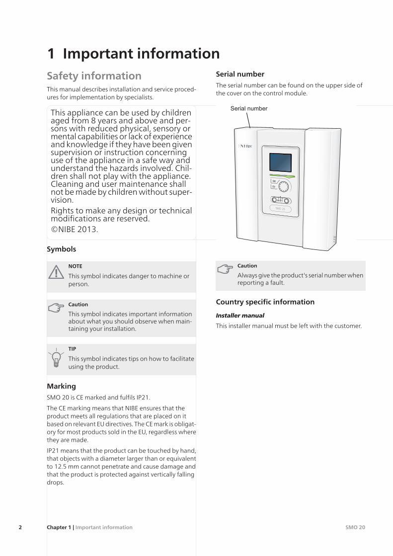
Serial number
The serial number can be found on the upper side ofthe cover on the control module.
LEK
Caution
Always give the product's serial number whenreporting a fault.
Country specific information
Installer manual
This installer manual must be left with the customer.
SMO 20Chapter 1 | Important information2
1 Important information
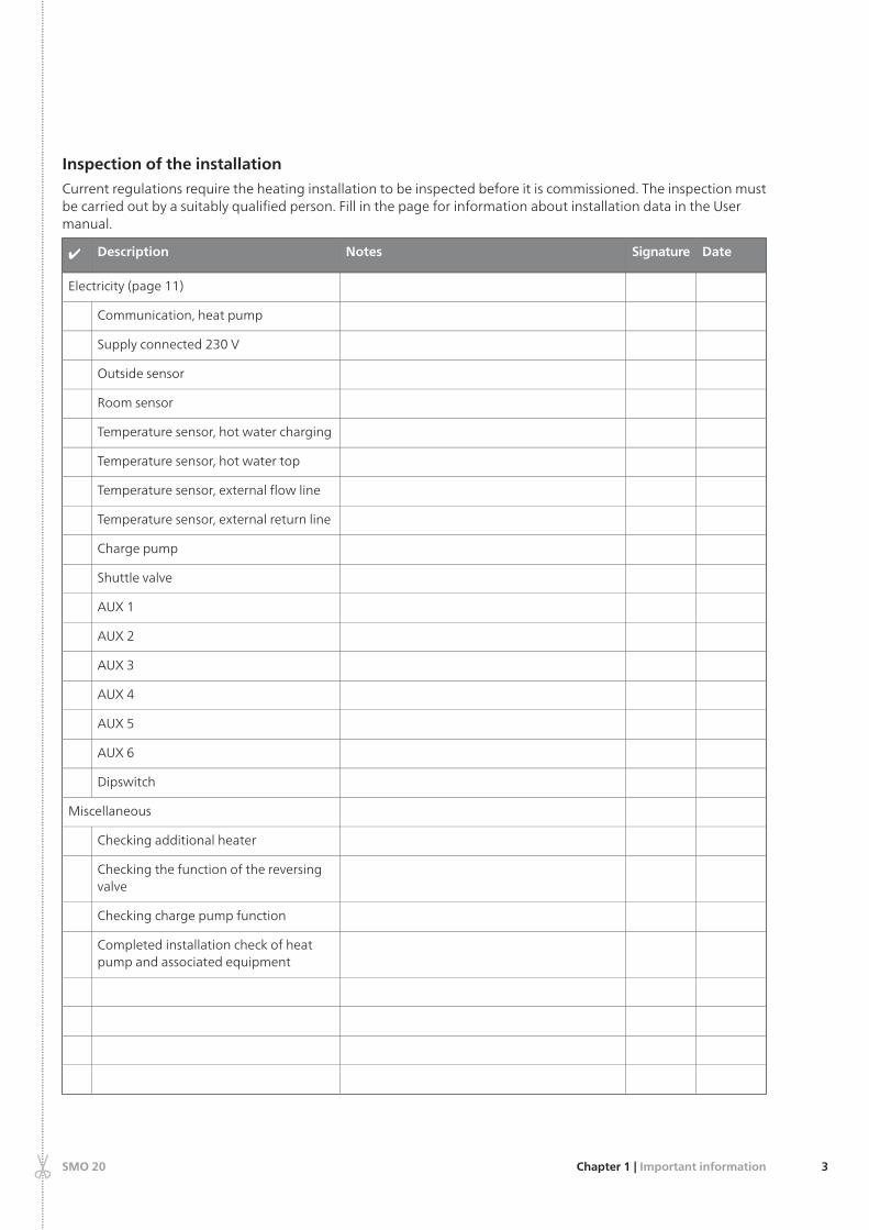
Inspection of the installation
Current regulations require the heating installation to be inspected before it is commissioned. The inspection mustbe carried out by a suitably qualified person. Fill in the page for information about installation data in the Usermanual.
DateSignatureNotesDescription✔
Electricity (page 11)
Communication, heat pump
Supply connected 230 V
Outside sensor
Room sensor
Temperature sensor, hot water charging
Temperature sensor, hot water top
Temperature sensor, external flow line
Temperature sensor, external return line
Charge pump
Shuttle valve
AUX 1
AUX 2
AUX 3
AUX 4
AUX 5
AUX 6
Dipswitch
Miscellaneous
Checking additional heater
Checking the function of the reversingvalve
Checking charge pump function
Completed installation check of heatpump and associated equipment
3Chapter 1 | Important informationSMO 20
......
......
......
......
......
......
......
......
......
......
......
......
......
......
......
......
......
......
......
......
......
......
......
......
......
......
......
......
......
......
......
......
......
......
......
......
......
......
......
......
......
......
......
......
......
......
......
......
......
......
......
......
......
......
......
......
......
......
......
......
......
......
......
......
......
......
......
......
......
......
......
......
......
......
......
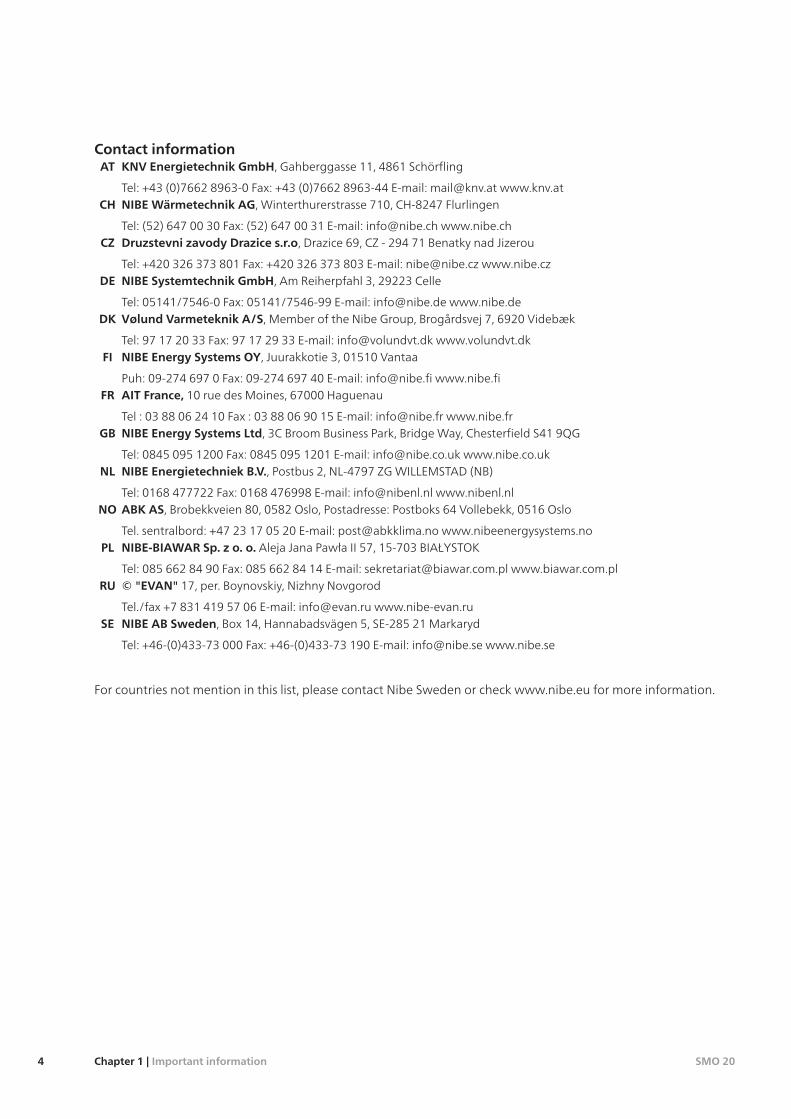
Contact informationKNV Energietechnik GmbH, Gahberggasse 11, 4861 SchörflingAT
Tel: +43 (0)7662 8963-0 Fax: +43 (0)7662 8963-44 E-mail: [email protected] www.knv.atNIBE Wärmetechnik AG, Winterthurerstrasse 710, CH-8247 FlurlingenCH
Tel: (52) 647 00 30 Fax: (52) 647 00 31 E-mail: [email protected] www.nibe.chDruzstevni zavody Drazice s.r.o, Drazice 69, CZ - 294 71 Benatky nad JizerouCZ
Tel: +420 326 373 801 Fax: +420 326 373 803 E-mail: [email protected] www.nibe.czNIBE Systemtechnik GmbH, Am Reiherpfahl 3, 29223 CelleDE
Tel: 05141/7546-0 Fax: 05141/7546-99 E-mail: [email protected] www.nibe.deVølund Varmeteknik A/S, Member of the Nibe Group, Brogårdsvej 7, 6920 VidebækDK
Tel: 97 17 20 33 Fax: 97 17 29 33 E-mail: [email protected] www.volundvt.dkNIBE Energy Systems OY, Juurakkotie 3, 01510 VantaaFI
Puh: 09-274 697 0 Fax: 09-274 697 40 E-mail: [email protected] www.nibe.fiAIT France, 10 rue des Moines, 67000 HaguenauFR
Tel : 03 88 06 24 10 Fax : 03 88 06 90 15 E-mail: [email protected] www.nibe.frNIBE Energy Systems Ltd, 3C Broom Business Park, Bridge Way, Chesterfield S41 9QGGB
Tel: 0845 095 1200 Fax: 0845 095 1201 E-mail: [email protected] www.nibe.co.ukNIBE Energietechniek B.V., Postbus 2, NL-4797 ZG WILLEMSTAD (NB)NL
Tel: 0168 477722 Fax: 0168 476998 E-mail: [email protected] www.nibenl.nlABK AS, Brobekkveien 80, 0582 Oslo, Postadresse: Postboks 64 Vollebekk, 0516 OsloNO
Tel. sentralbord: +47 23 17 05 20 E-mail: [email protected] www.nibeenergysystems.noNIBE-BIAWAR Sp. z o. o. Aleja Jana Pawła II 57, 15-703 BIAŁYSTOKPL
Tel: 085 662 84 90 Fax: 085 662 84 14 E-mail: [email protected] www.biawar.com.pl© "EVAN" 17, per. Boynovskiy, Nizhny NovgorodRU
Tel./fax +7 831 419 57 06 E-mail: [email protected] www.nibe-evan.ruNIBE AB Sweden, Box 14, Hannabadsvägen 5, SE-285 21 MarkarydSE
Tel: +46-(0)433-73 000 Fax: +46-(0)433-73 190 E-mail: [email protected] www.nibe.se
For countries not mention in this list, please contact Nibe Sweden or check www.nibe.eu for more information.
SMO 20Chapter 1 | Important information4
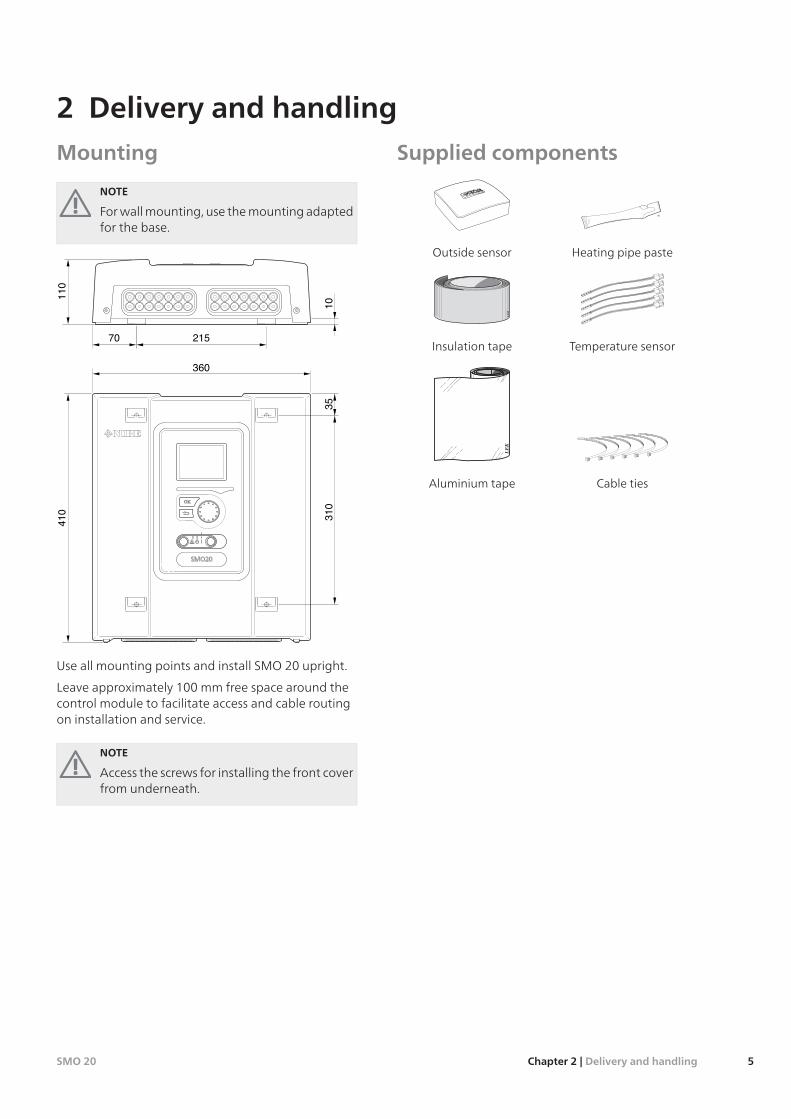
Mounting
NOTE
For wall mounting, use the mounting adaptedfor the base.
110
410
360
1031
021570
35
Use all mounting points and install SMO 20 upright.
Leave approximately 100 mm free space around thecontrol module to facilitate access and cable routingon installation and service.
NOTE
Access the screws for installing the front coverfrom underneath.
Supplied components
Heating pipe pasteOutside sensor
LE
K
Temperature sensorInsulation tape
LE
K
Cable tiesAluminium tape
5Chapter 2 | Delivery and handlingSMO 20
2 Delivery and handling
LEK
L N 1 1 0 2 3 4PE
2120
1918
1716
1514
1312
1110
98
76
54
32
1
LEK
L N 1 1 0 2 3 4PE
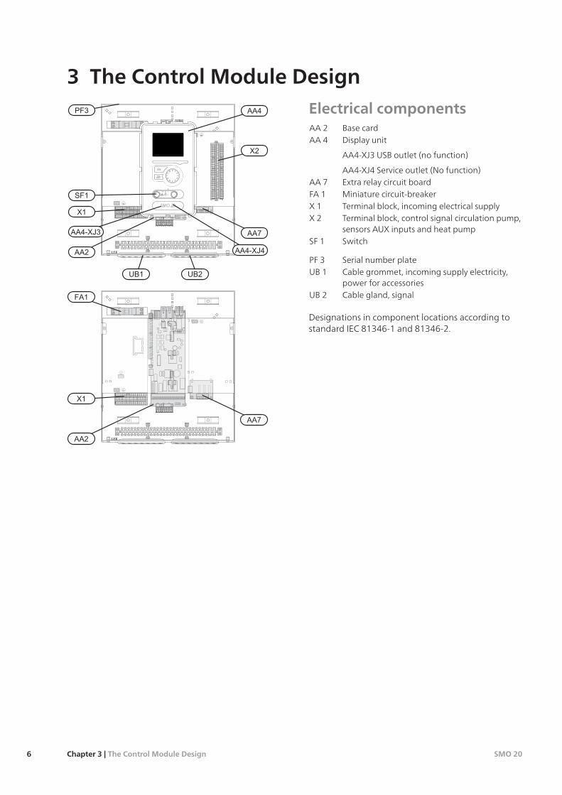
Electrical componentsBase cardAA 2Display unitAA 4
AA4-XJ3 USB outlet (no function)
AA4-XJ4 Service outlet (No function)Extra relay circuit boardAA 7Miniature circuit-breakerFA 1Terminal block, incoming electrical supplyX 1Terminal block, control signal circulation pump,sensors AUX inputs and heat pump
X 2
SwitchSF 1
Serial number platePF 3Cable grommet, incoming supply electricity,power for accessories
UB 1
Cable gland, signalUB 2
Designations in component locations according tostandard IEC 81346-1 and 81346-2.
SMO 20Chapter 3 | The Control Module Design6
3 The Control Module Design
GeneralPipe installation must be carried out in accordance withcurrent norms and directives. See manual for compat-ible NIBE air/water heat pump for installation of theheat pump.
Compatible NIBE air/water heat pumps
Compatible NIBE air/water heat pumps must beequipped with a control card that has at least thesoftware version given in the following list. The controlcard version is displayed in the heat pump's display (ifapplicable) upon start-up.
Software versionProduct
55F2015
55F2016
55F2025
55F2026
all versionsF2030
all versionsF2040
55F2300
Symbol key
MeaningSymbol
Shut-off valve
Non-return valve
Shunt / shuttle valve
Safety valve
Trim valve
Temperature sensor
Pressure gaugeP
Circulation pump
Particle filter
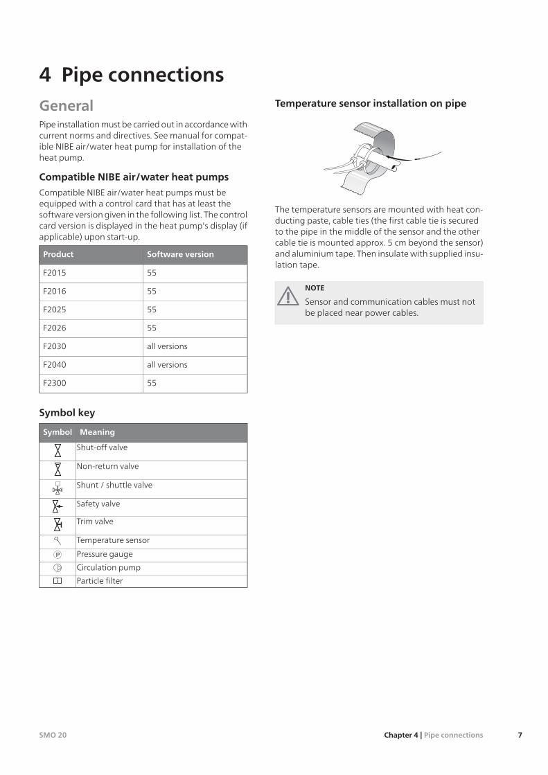
Temperature sensor installation on pipe
K
The temperature sensors are mounted with heat con-ducting paste, cable ties (the first cable tie is securedto the pipe in the middle of the sensor and the othercable tie is mounted approx. 5 cm beyond the sensor)and aluminium tape. Then insulate with supplied insu-lation tape.
NOTE
Sensor and communication cables must notbe placed near power cables.
7Chapter 4 | Pipe connectionsSMO 20
4 Pipe connections

Docking alternativesSMO 20 can be connected with other products fromNIBE in several different ways, some of which are shownbelow (accessories may be required).
Further option information is available at www.nibe.euand in the respective assembly instructions for the ac-cessories used. See page 49 for a list of the accessoriesthat can be used with SMO 20.
Installations with SMO 20 can produce heating andhot water.
On cold days of the year when the access to energyfrom the air is reduced the additional heating cancompensate and help to produce heat. The additionalheating is also good to have as assistance if the heatpump ends up outside its working range or if it hasbeen blocked for any reason.
NOTE
The heating medium side and the hot waterside must be fitted with the necessary safetyequipment in accordance with the applicableregulations.
This is the outline diagram. Actual installationsmust be planned according to applicablestandards.
ExplanationSMO 20AA25Outside sensorBT1Temperature sensor, hot water chargingBT6Temperature sensor, hot water topBT7Temperature sensor, external flow lineBT25Room sensorBT50Temperature sensor, external supply lineafter electric heater
BT63
Temperature sensor, external return lineBT71Circulation pump, Heating mediumGP10Reversing valve, Hot water/Heating medi-um
QN10
Additional heatEB1Immersion heaterEB1Auxiliary relay/ContactorKA1Heat pump systemEB101Temperature sensor, returnBT3Temperature sensor, condenser supply lineBT12Heat pumpEB101Safety valveFL10Charge pumpGP12Particle filterHQ1Drain valve, Heating mediumQM1Shut-off valve, Heating medium, FlowQM31Shut off valve, Heating medium, ReturnQM32
Shut-off valveQM43Miscel-laneous
Expansion vessel closed, Hot waterCM1Buffer vessel (UKV)CP5Accumulator tank with hot water heatingCP10Immersion heaterEB20Safety valve, Heating mediumFL2Auxiliary relay/ContactorKA1Control valveRN10
Designations according to standards 81346-1 and81346-2.
SMO 20Chapter 4 | Pipe connections8
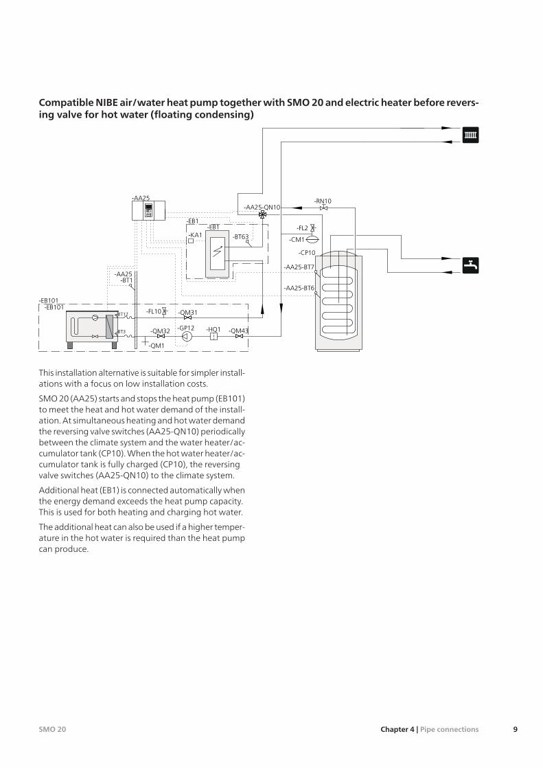
CompatibleNIBE air/water heat pump togetherwith SMO20and electric heater before revers-ing valve for hot water (floating condensing)
-FL2
-CM1
-EB101
-QM1
-BT3
-BT12 -QM31
-QM32 -QM43-GP12
-EB101
-HQ1
-BT1
-AA25
-AA25
-BT63-KA1
-EB1
-FL10
-RN10
-CP10
-AA25-QN10
-AA25-BT7
-AA25-BT6
-EB1
This installation alternative is suitable for simpler install-ations with a focus on low installation costs.
SMO 20 (AA25) starts and stops the heat pump (EB101)to meet the heat and hot water demand of the install-ation. At simultaneous heating and hot water demandthe reversing valve switches (AA25-QN10) periodicallybetween the climate system and the water heater/ac-cumulator tank (CP10). When the hot water heater/ac-cumulator tank is fully charged (CP10), the reversingvalve switches (AA25-QN10) to the climate system.
Additional heat (EB1) is connected automatically whenthe energy demand exceeds the heat pump capacity.This is used for both heating and charging hot water.
The additional heat can also be used if a higher temper-ature in the hot water is required than the heat pumpcan produce.
9Chapter 4 | Pipe connectionsSMO 20
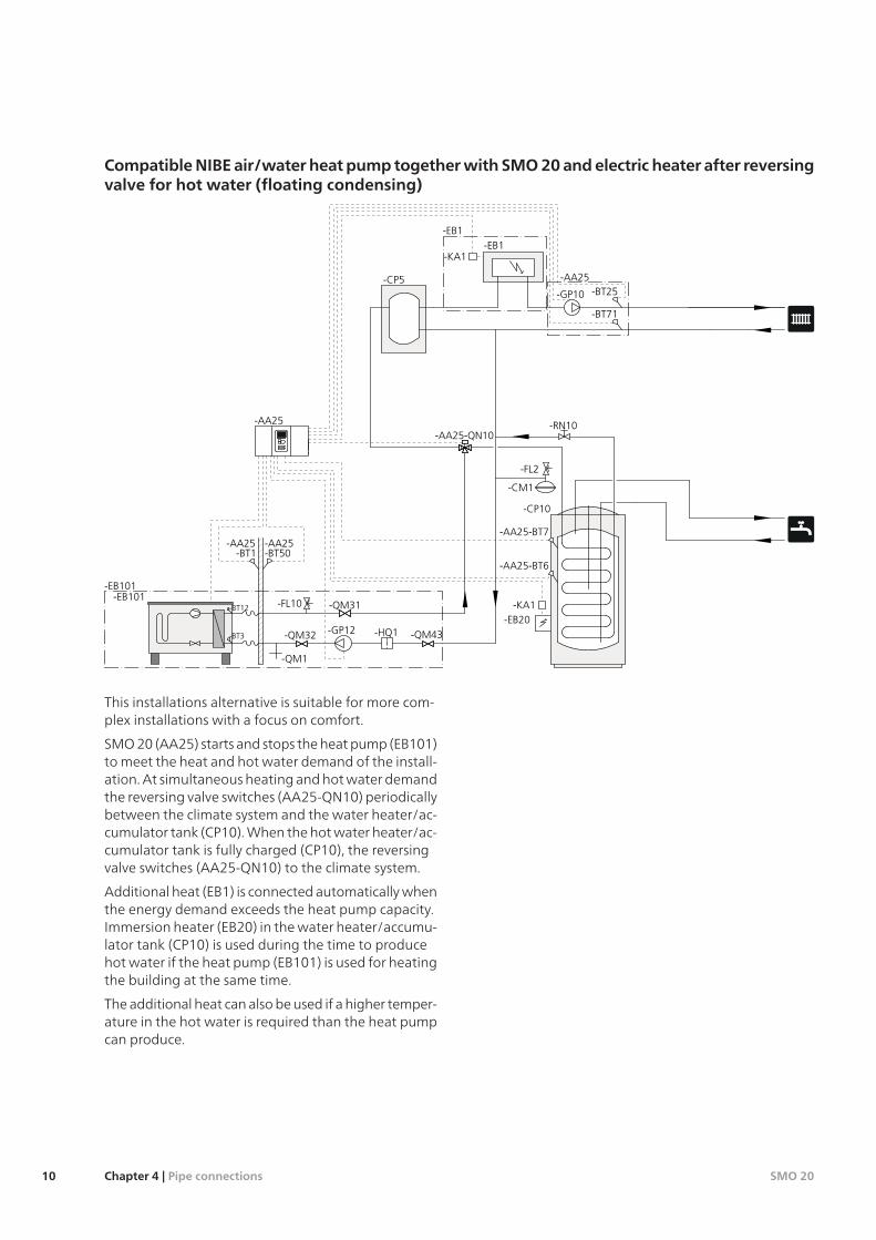
CompatibleNIBE air/water heat pump togetherwith SMO20andelectric heater after reversingvalve for hot water (floating condensing)
-EB20-KA1
-FL2
-CM1
-EB101
-QM1
-BT3
-BT12 -QM31
-QM32 -QM43-GP12
-EB101
-HQ1
-BT1
-AA25
-AA25 -AA25
-FL10
-RN10
-CP10
-AA25-QN10
-AA25-BT7
-AA25-BT6
-BT25
-EB1
-CP5-GP10
-KA1
-BT71
-EB1
-AA25
-BT50
This installations alternative is suitable for more com-plex installations with a focus on comfort.
SMO 20 (AA25) starts and stops the heat pump (EB101)to meet the heat and hot water demand of the install-ation. At simultaneous heating and hot water demandthe reversing valve switches (AA25-QN10) periodicallybetween the climate system and the water heater/ac-cumulator tank (CP10). When the hot water heater/ac-cumulator tank is fully charged (CP10), the reversingvalve switches (AA25-QN10) to the climate system.
Additional heat (EB1) is connected automatically whenthe energy demand exceeds the heat pump capacity.Immersion heater (EB20) in the water heater/accumu-lator tank (CP10) is used during the time to producehot water if the heat pump (EB101) is used for heatingthe building at the same time.
The additional heat can also be used if a higher temper-ature in the hot water is required than the heat pumpcan produce.
SMO 20Chapter 4 | Pipe connections10
GeneralDisconnect SMO 20 before insulation testing thehouse wiring.
If the building is equipped with an earth-faultbreaker, SMO 20 should be equipped with a separ-ate one.
SMO 20 must be installed via an isolator switch witha minimum breaking gap of 3mm.
For the electrical wiring diagram for the controlmodule, see page 53.
Communication and sensor cables to external con-nections must not be laid close to high currentcables.
The minimum area of communication and sensorcables to external connections must be 0.5 mm² upto 50 m, for example EKKX or LiYY or equivalent.
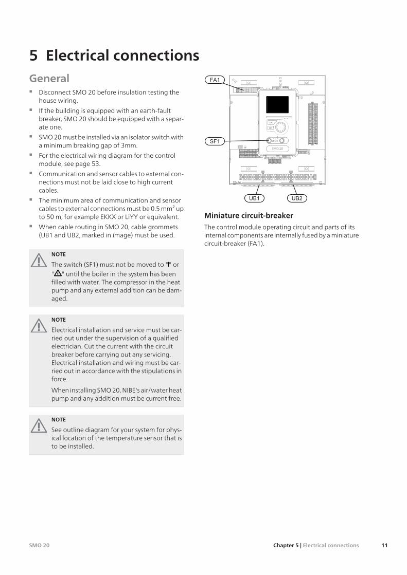
When cable routing in SMO 20, cable grommets(UB1 and UB2, marked in image) must be used.
NOTE
The switch (SF1) must not be moved to "" or" " until the boiler in the system has beenfilled with water. The compressor in the heatpump and any external addition can be dam-aged.
NOTE
Electrical installation and service must be car-ried out under the supervision of a qualifiedelectrician. Cut the current with the circuitbreaker before carrying out any servicing.Electrical installation and wiring must be car-ried out in accordance with the stipulations inforce.
When installing SMO 20, NIBE's air/water heatpump and any addition must be current free.
NOTE
See outline diagram for your system for phys-ical location of the temperature sensor that isto be installed.
LEK
L N 1 1 0 2 3 4PE
2120
1918
1716
1514
1312
1110
98
76
54
32
1
Miniature circuit-breaker
The control module operating circuit and parts of itsinternal components are internally fused by a miniaturecircuit-breaker (FA1).
11Chapter 5 | Electrical connectionsSMO 20
5 Electrical connections
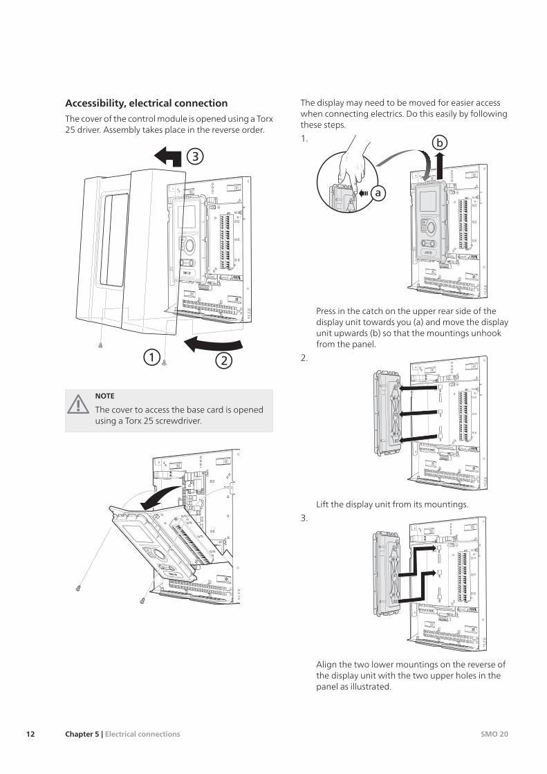
Accessibility, electrical connection
The cover of the control module is opened using a Torx25 driver. Assembly takes place in the reverse order.
LEK
3
21
NOTE
The cover to access the base card is openedusing a Torx 25 screwdriver.
LEK
The display may need to be moved for easier accesswhen connecting electrics. Do this easily by followingthese steps.
1.
LEK
b
a
Press in the catch on the upper rear side of thedisplay unit towards you (a) and move the displayunit upwards (b) so that the mountings unhookfrom the panel.
2.
LEK
Lift the display unit from its mountings.
3.
LEK
Align the two lower mountings on the reverse ofthe display unit with the two upper holes in thepanel as illustrated.
SMO 20Chapter 5 | Electrical connections12

4.
LEK
Secure the display on the panel.
5. When the electrical connection is ready the displaymust be reinstalled with three mounting pointsagain, otherwise the front cover cannot be in-stalled.
Cable lock
Use a suitable tool to release/lock cables in the heatpump terminal blocks.
Terminal block on the electrical card
2
1
2
3
LEK
3
4
1
2
Terminal block
LEK
1 mm
3,5 mm
13Chapter 5 | Electrical connectionsSMO 20
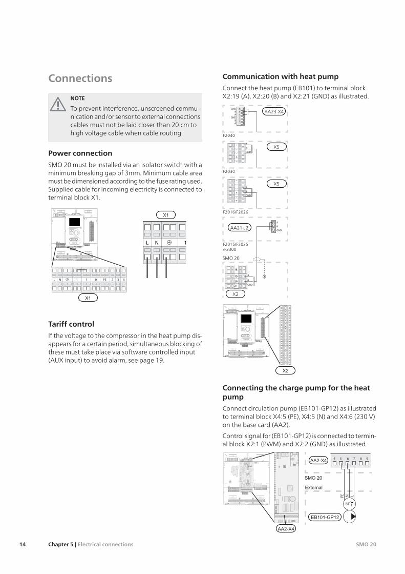
Connections
NOTE
To prevent interference, unscreened commu-nication and/or sensor to external connectionscables must not be laid closer than 20 cm tohigh voltage cable when cable routing.
Power connection
SMO 20 must be installed via an isolator switch with aminimum breaking gap of 3mm. Minimum cable areamust be dimensioned according to the fuse rating used.Supplied cable for incoming electricity is connected toterminal block X1.
1NL
LEK
L N 1 1 0 2 3 4PE
2120
1918
1716
1514
1312
1110
98
76
54
32
1
1 1NL 0 432PE
Tariff control
If the voltage to the compressor in the heat pump dis-appears for a certain period, simultaneous blocking ofthese must take place via software controlled input(AUX input) to avoid alarm, see page 19.
Communication with heat pump
Connect the heat pump (EB101) to terminal blockX2:19 (A), X2:20 (B) and X2:21 (GND) as illustrated.
654321
A
B
GND
A
B
GND
A
B
GND
SMO
F2015/F2025/F2300
F2016/F2026
56
42
31
A
B
GND
F20305
42
31
A
B
GND
A
B
GND
F2040
19
20
21
18
X2
AA21-J2
X5
X5
AA23-X4
SMO 20
LEK
L N 1 1 0 2 3 4PE
2120
1918
1716
1514
1312
1110
98
76
54
32
1
5
6
7
2
1
8
9
13
12
4
3
11
10
19
20
21
14
18
16
17
15
Connecting the charge pump for the heatpump
Connect circulation pump (EB101-GP12) as illustratedto terminal block X4:5 (PE), X4:5 (N) and X4:6 (230 V)on the base card (AA2).
Control signal for (EB101-GP12) is connected to termin-al block X2:1 (PWM) and X2:2 (GND) as illustrated.
987654
SMO
Externt
PE LN
L N 1 1 0 2 3 4PE
1 2 3 4
LEK
1 2 3 4
SMO 20Chapter 5 | Electrical connections14
2
1
4
3
SMO
ExterntLEK
L N 1 1 0 2 3 4PE
2120
1918
1716
1514
1312
1110
98
76
54
32
1
5
6
7
2
1
8
9
13
12
4
3
11
10
19
20
21
14
18
16
17
15
NOTE
If the charge pumps are not correctly connec-ted at start up the control module receives analarm.
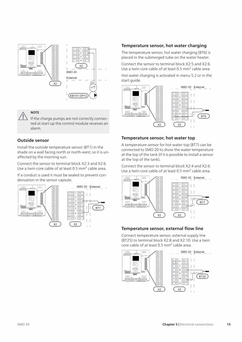
Outside sensor
Install the outside temperature sensor (BT1) in theshade on a wall facing north or north-west, so it is un-affected by the morning sun.
Connect the sensor to terminal block X2:3 and X2:6.Use a twin core cable of at least 0.5 mm² cable area.
If a conduit is used it must be sealed to prevent con-densation in the sensor capsule.
SMO Externt
5
6
7
2
1
4
3
LEK
L N 1 1 0 2 3 4PE
2120
1918
1716
1514
1312
1110
98
76
54
32
1
5
6
7
2
1
8
9
13
12
4
3
11
10
19
20
21
14
18
16
17
15
Temperature sensor, hot water charging
The temperature sensor, hot water charging (BT6) isplaced in the submerged tube on the water heater.
Connect the sensor to terminal block X2:5 and X2:6.Use a twin core cable of at least 0.5 mm² cable area.
Hot water charging is activated in menu 5.2 or in thestart guide.
SMO Externt
5
6
7
2
1
4
3
LEK
L N 1 1 0 2 3 4PE
2120
1918
1716
1514
1312
1110
98
76
54
32
1
5
6
7
2
1
8
9
13
12
4
3
11
10
19
20
21
14
18
16
17
15
Temperature sensor, hot water top
A temperature sensor for hot water top (BT7) can beconnected to SMO 20 to show the water temperatureat the top of the tank (if it is possible to install a sensorat the top of the tank).
Connect the sensor to terminal block X2:4 and X2:6.Use a twin core cable of at least 0.5 mm² cable area.
SMO Externt
5
6
7
2
1
4
3
LEK
L N 1 1 0 2 3 4PE
2120
1918
1716
1514
1312
1110
98
76
54
32
1
5
6
7
2
1
8
9
13
12
4
3
11
10
19
20
21
14
18
16
17
15
Temperature sensor, external flow line
Connect temperature sensor, external supply line(BT25) to terminal block X2:8 and X2:10. Use a twincore cable of at least 0.5 mm² cable area.
SMO Externt
9
10
11
6
8
7
LEK
L N 1 1 0 2 3 4PE
2120
1918
1716
1514
1312
1110
98
76
54
32
1
5
6
7
2
1
8
9
13
12
4
3
11
10
19
20
21
14
18
16
17
15
15Chapter 5 | Electrical connectionsSMO 20
Temperature sensor, external supply lineafter electric heater
Connect temperature sensor, external supply line afterelectric heater (BT63) to terminal block X2:9 and X2:10.Use a twin core cable of at least 0.5 mm² cable area.
SMO Externt
9
10
11
6
8
7
LEK
L N 1 1 0 2 3 4PE
2120
1918
1716
1514
1312
1110
98
76
54
32
1
5
6
7
2
1
8
9
13
12
4
3
11
10
19
20
21
14
18
16
17
15
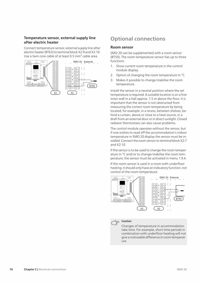
Optional connectionsRoom sensor
SMO 20 can be supplemented with a room sensor(BT50). The room temperature sensor has up to threefunctions:
1. Show current room temperature in the controlmodule display.
2. Option of changing the room temperature in °C.
3. Makes it possible to change/stabilise the roomtemperature.
Install the sensor in a neutral position where the settemperature is required. A suitable location is on a freeinner wall in a hall approx. 1.5 m above the floor. It isimportant that the sensor is not obstructed frommeasuring the correct room temperature by beinglocated, for example, in a recess, between shelves, be-hind a curtain, above or close to a heat source, in adraft from an external door or in direct sunlight. Closedradiator thermostats can also cause problems.
The control module operates without the sensor, butif one wishes to read off the accommodation's indoortemperature in SMO 20 display the sensor must be in-stalled. Connect the room sensor to terminal block X2:7and X2:10.
If the sensor is to be used to change the room temper-ature in °C and/or to change/stabilise the room tem-perature, the sensor must be activated in menu 1.9.4.
If the room sensor is used in a room with underfloorheating, it should only have an indicatory function, notcontrol of the room temperature.
9
10
11
6
8
7
LEK
L N 1 1 0 2 3 4PE
2120
1918
1716
1514
1312
1110
98
76
54
32
1
5
6
7
2
1
8
9
13
12
4
3
11
10
19
20
21
14
18
16
17
15
Caution
Changes of temperature in accommodationtake time. For example, short time periods incombination with underfloor heating will notgive a noticeable difference in room temperat-ure.
SMO 20Chapter 5 | Electrical connections16
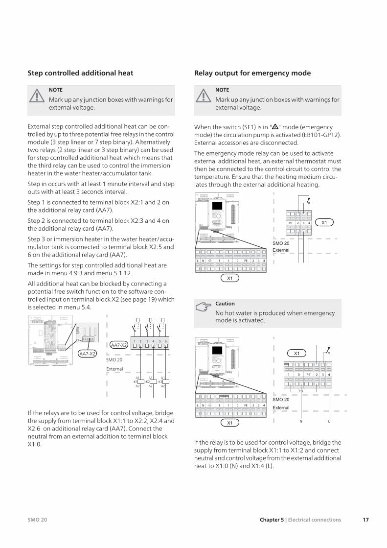
Step controlled additional heat
NOTE
Mark up any junction boxes with warnings forexternal voltage.
External step controlled additional heat can be con-trolled by up to three potential free relays in the controlmodule (3 step linear or 7 step binary). Alternativelytwo relays (2 step linear or 3 step binary) can be usedfor step controlled additional heat which means thatthe third relay can be used to control the immersionheater in the water heater/accumulator tank.
Step in occurs with at least 1 minute interval and stepouts with at least 3 seconds interval.
Step 1 is connected to terminal block X2:1 and 2 onthe additional relay card (AA7).
Step 2 is connected to terminal block X2:3 and 4 onthe additional relay card (AA7).
Step 3 or immersion heater in the water heater/accu-mulator tank is connected to terminal block X2:5 and6 on the additional relay card (AA7).
The settings for step controlled additional heat aremade in menu 4.9.3 and menu 5.1.12.
All additional heat can be blocked by connecting apotential free switch function to the software con-trolled input on terminal block X2 (see page 19) whichis selected in menu 5.4.
654321
SMO
Externt
A1
A2
A1
A2
A1-K1 -K2 -K3
A2
External
SMO 20
AA7-X2
LEK
L N 1 1 0 2 3 4PE
-X2
1
123456
2 3 4 5 6
-X1
AA7-X2
If the relays are to be used for control voltage, bridgethe supply from terminal block X1:1 to X2:2, X2:4 andX2:6 on additional relay card (AA7). Connect theneutral from an external addition to terminal blockX1:0.
Relay output for emergency mode
NOTE
Mark up any junction boxes with warnings forexternal voltage.
When the switch (SF1) is in " " mode (emergencymode) the circulation pump is activated (EB101-GP12).External accessories are disconnected.
The emergency mode relay can be used to activateexternal additional heat, an external thermostat mustthen be connected to the control circuit to control thetemperature. Ensure that the heating medium circu-lates through the external additional heating.
432PE
SMO
Externt
LEK
L N 1 1 0 2 3 4PE
2120
1918
1716
1514
1312
1110
98
76
54
32
1
1 1NL 0 432PE
Caution
No hot water is produced when emergencymode is activated.
1 0 432PE
SMO
Externt
N L
LEK
L N 1 1 0 2 3 4PE
2120
1918
1716
1514
1312
1110
98
76
54
32
1
1 1NL 0 432PE
If the relay is to be used for control voltage, bridge thesupply from terminal block X1:1 to X1:2 and connectneutral and control voltage from the external additionalheat to X1:0 (N) and X1:4 (L).
17Chapter 5 | Electrical connectionsSMO 20
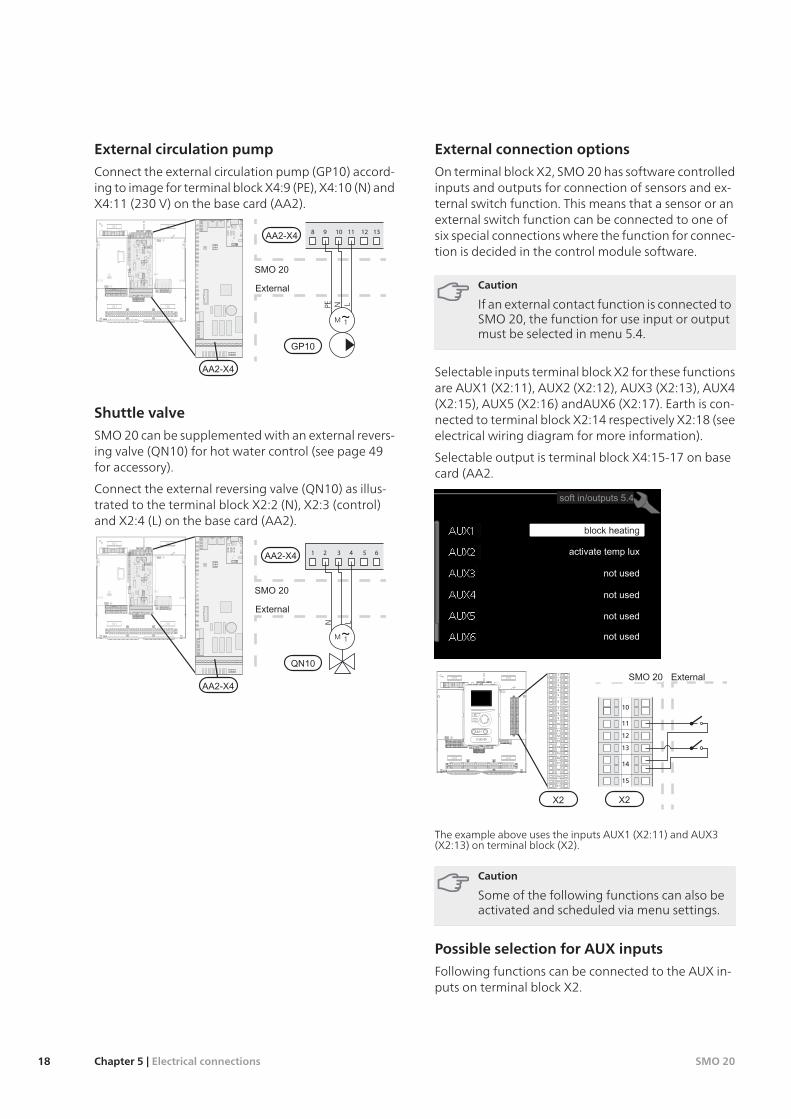
External circulation pump
Connect the external circulation pump (GP10) accord-ing to image for terminal block X4:9 (PE), X4:10 (N) andX4:11 (230 V) on the base card (AA2).
1312111098
SMO
Externt
PE LN
LEK
L N 1 1 0 2 3 4PE
Shuttle valve
SMO 20 can be supplemented with an external revers-ing valve (QN10) for hot water control (see page 49for accessory).
Connect the external reversing valve (QN10) as illus-trated to the terminal block X2:2 (N), X2:3 (control)and X2:4 (L) on the base card (AA2).
654321
SMO
Externt
N L
LEK
L N 1 1 0 2 3 4PE
External connection options
On terminal block X2, SMO 20 has software controlledinputs and outputs for connection of sensors and ex-ternal switch function. This means that a sensor or anexternal switch function can be connected to one ofsix special connections where the function for connec-tion is decided in the control module software.
Caution
If an external contact function is connected toSMO 20, the function for use input or outputmust be selected in menu 5.4.
Selectable inputs terminal block X2 for these functionsare AUX1 (X2:11), AUX2 (X2:12), AUX3 (X2:13), AUX4(X2:15), AUX5 (X2:16) andAUX6 (X2:17). Earth is con-nected to terminal block X2:14 respectively X2:18 (seeelectrical wiring diagram for more information).
Selectable output is terminal block X4:15-17 on basecard (AA2.
B
SMO Externt
13
14
15
10
12
11
ALEK
L N 1 1 0 2 3 4PE
2120
1918
1716
1514
1312
1110
98
76
54
32
1
5
6
7
2
1
8
9
13
12
4
3
11
10
19
20
21
14
18
16
17
15
The example above uses the inputs AUX1 (X2:11) and AUX3(X2:13) on terminal block (X2).
Caution
Some of the following functions can also beactivated and scheduled via menu settings.
Possible selection for AUX inputs
Following functions can be connected to the AUX in-puts on terminal block X2.
SMO 20Chapter 5 | Electrical connections18
Temperature sensor, external return line
If temperature sensor, external return line (BT71)needs to be used, connect it to selected input (menu5.4, see page 41) on terminal block X2. Use a 2 corecable of at least 0.5 mm2 cable area.Switch for external blocking of additional heat
In those cases where external blocking of additionalheat is desired, this can be connected to terminalblock X2.
The additional heat is disconnected by connectinga potential free switch function to the input selectedin menu 5.4.
A closed contact results in the electrical output be-ing disconnected.Contact for external blocking of compressor inthe heat pump
In those cases external blocking of compressor inthe heat pump is desired, this can be connected toterminal block X2.
The compressor in the heat pump is disconnectedby connecting a potential free switch function tothe input selected in menu 5.4.
A closed contact results in the electrical output be-ing disconnected.Contact for external tariff blocking
In cases where external tariff blocking is requiredit must be connected to terminal block X2.
Tariff blocking means that the additional heat, thecompressor and heating are disconnected by con-necting a potential free switch function to the inputselected in menu 5.4.
A closed contact results in the electrical output be-ing disconnected.Switch for "SG ready"
NOTE
This function can only be used in electri-city supply networks that support the"SG Ready" standard (Germany).
"SG Ready" requires two AUX inputs.
In cases where this function is required it must beconnected to terminal block X2.
"SG Ready" is a smart form of tariff control whereyour electricity supplier can affect the indoor, hotwater and/or pool temperatures (if applicable) orsimply block the additional heat and/or compressorin the heat pump at certain times of the day (canbe selected in menu 4.1.5 after the function is activ-ated). Activate the function by connecting potential
free switch functions to two inputs selected in menu5.4 (SG Ready A and SG Ready B), see page41.
Closed or open switch means one of the following(A = SG Ready A and B = SG Ready B ):
Blocking (A: Closed, B: Open)
"SG Ready" is active. The compressor in the heatpump and additional heat is blocked like theday's tariff blocking.
Normal mode (A: Open, B: Open)
"SG Ready" is not active. No effect on the system.
Low price mode (A: Open, B: Closed)
"SG Ready" is active. The system focuses on costssavings and can for example exploit a low tarifffrom the electricity supplier or over capacityfrom any own power source (effect on the sys-tem can be adjusted in the menu 4.1.5).
Overcapacity mode (A: Closed, B: Closed)
"SG Ready" is active. The system is permitted torun at full capacity at over capacity with theelectricity supplier (effect on the system is set-table in menu 4.1.5).
Switch for external blocking of heating
In those cases where external blocking of heat isdesired, this can be connected to terminal block X2.
Heating is disconnected by connecting a potentialfree switch function to the input selected in menu5.4.
A closed switch results in blocked heating operation.Contact for activation of “temporary lux"
An external switch function can be connected toSMO 20 for activation of the hot water function"temporary lux". The switch must be potential freeand connected to the selected input (menu 5.4) onterminal block X2.
"temporary lux" is activated for the time that thecontact is connected.Contact for activation of “external adjustment"
An external contact function can be connected toSMO 20 to change the supply temperature and theroom temperature.
When the switch is closed the temperature changesin °C (if the room sensor is connected and activated).If a room sensor is not connected or not activated,the desired offset of "temperature" (heating curveoffset) is set with the number of steps selected. Thevalue is adjustable between -10 and +10.
climate system 1
The switch must be potential free and connectedto the selected input (menu 5.4) on terminalblock X2.
19Chapter 5 | Electrical connectionsSMO 20
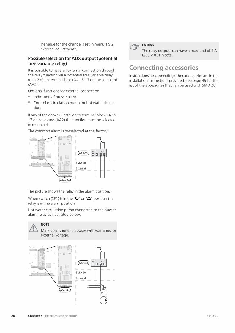
The value for the change is set in menu 1.9.2,"external adjustment".
Possible selection for AUXoutput (potentialfree variable relay)
It is possible to have an external connection throughthe relay function via a potential free variable relay(max 2 A) on terminal block X4:15-17 on the base card(AA2).
Optional functions for external connection:
Indication of buzzer alarm.
Control of circulation pump for hot water circula-tion.
If any of the above is installed to terminal block X4:15-17 on base card (AA2) the function must be selectedin menu 5.4
The common alarm is preselected at the factory.
17161514
SMO
ExterntLEK
L N 1 1 0 2 3 4PE
The picture shows the relay in the alarm position.
When switch (SF1) is in the " " or “ ” position therelay is in the alarm position.
Hot water circulation pump connected to the buzzeralarm relay as illustrated below.
NOTE
Mark up any junction boxes with warnings forexternal voltage.
17161514
SMO
Externt
L
L
N
N
PEPE
LEK
L N 1 1 0 2 3 4PE
Caution
The relay outputs can have a max load of 2 A(230 V AC) in total.
Connecting accessoriesInstructions for connecting other accessories are in theinstallation instructions provided. See page 49 for thelist of the accessories that can be used with SMO 20.
SMO 20Chapter 5 | Electrical connections20
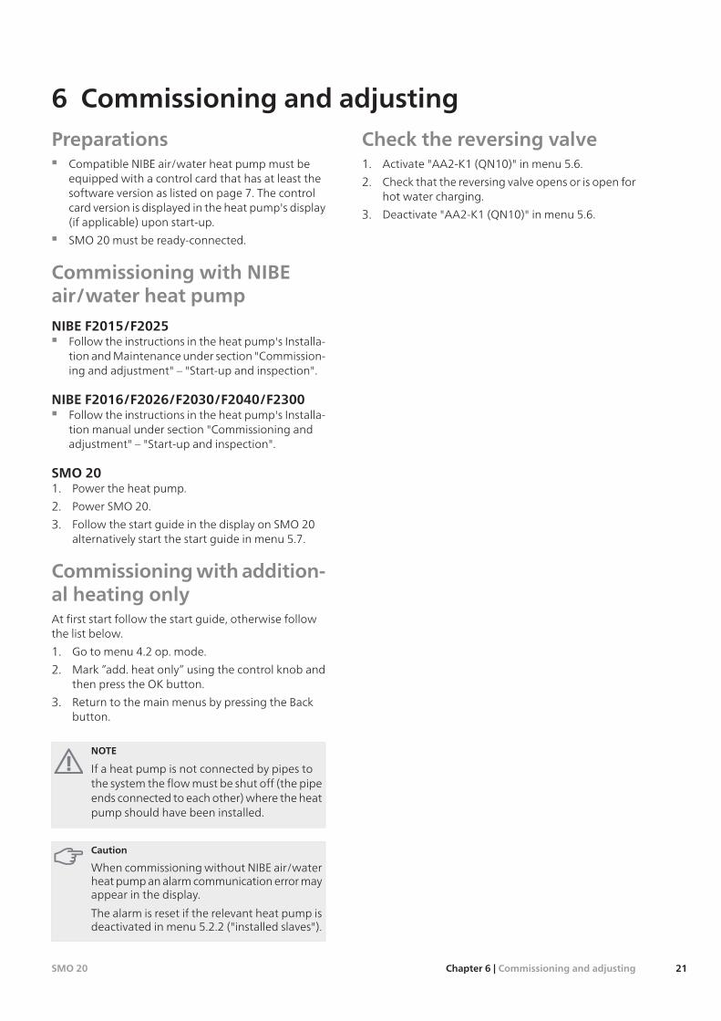
PreparationsCompatible NIBE air/water heat pump must beequipped with a control card that has at least thesoftware version as listed on page 7. The controlcard version is displayed in the heat pump's display(if applicable) upon start-up.
SMO 20 must be ready-connected.
Commissioning with NIBEair/water heat pumpNIBE F2015/F2025
Follow the instructions in the heat pump's Installa-tion and Maintenance under section "Commission-ing and adjustment" – "Start-up and inspection".
NIBE F2016/F2026/F2030/F2040/F2300Follow the instructions in the heat pump's Installa-tion manual under section "Commissioning andadjustment" – "Start-up and inspection".
SMO 201. Power the heat pump.
2. Power SMO 20.
3. Follow the start guide in the display on SMO 20alternatively start the start guide in menu 5.7.
Commissioningwith addition-al heating onlyAt first start follow the start guide, otherwise followthe list below.
1. Go to menu 4.2 op. mode.
2. Mark ”add. heat only” using the control knob andthen press the OK button.
3. Return to the main menus by pressing the Backbutton.
NOTE
If a heat pump is not connected by pipes tothe system the flow must be shut off (the pipeends connected to each other) where the heatpump should have been installed.
Caution
When commissioning without NIBE air/waterheat pump an alarm communication error mayappear in the display.
The alarm is reset if the relevant heat pump isdeactivated in menu 5.2.2 ("installed slaves").
Check the reversing valve1. Activate "AA2-K1 (QN10)" in menu 5.6.
2. Check that the reversing valve opens or is open forhot water charging.
3. Deactivate "AA2-K1 (QN10)" in menu 5.6.
21Chapter 6 | Commissioning and adjustingSMO 20
6 Commissioning and adjusting
Start guide
NOTE
There must be water in the climate systembefore the switch is set to " ".
1. Turn the control module switch (SF1) to "".
2. Follow the instructions in the start guide in thecontrol module display. If the start guide does notstart when you start the control module, start itmanually in menu 5.7.
TIP
See page 23 for a more in-depth introductionto the installation’s control system (operation,menus etc.).
Commissioning
The first time the installation is started a start guide isstarted. The start guide instructions state what needsto carried out at the first start together with a runthrough of the installation’s basic settings.
The start guide ensures that the start-up is carried outcorrectly and cannot be bypassed. The start guide canbe started later in menu 5.7.
During the start up guide the reversing valves and theshunt valve are run backward and forwards to helpvent SMO 20.
Caution
As long as the start guide is active, no functionin the heat pump will start automatically.
The guide will appear at each heat pump re-start until it is deselected on the last page.
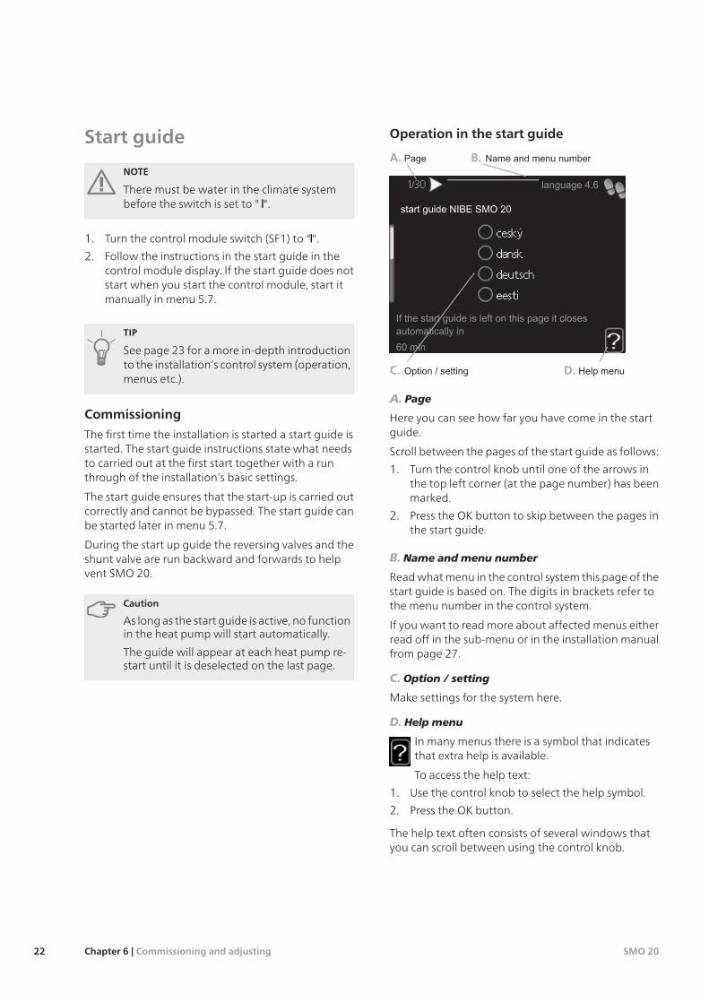
Operation in the start guide
A. B.
D.C.
A. Page
Here you can see how far you have come in the startguide.
Scroll between the pages of the start guide as follows:
1. Turn the control knob until one of the arrows inthe top left corner (at the page number) has beenmarked.
2. Press the OK button to skip between the pages inthe start guide.
B. Name and menu number
Read what menu in the control system this page of thestart guide is based on. The digits in brackets refer tothe menu number in the control system.
If you want to read more about affected menus eitherread off in the sub-menu or in the installation manualfrom page 27.
C. Option / setting
Make settings for the system here.
D. Help menu
In many menus there is a symbol that indicatesthat extra help is available.
To access the help text:
1. Use the control knob to select the help symbol.
2. Press the OK button.
The help text often consists of several windows thatyou can scroll between using the control knob.
SMO 20Chapter 6 | Commissioning and adjusting22
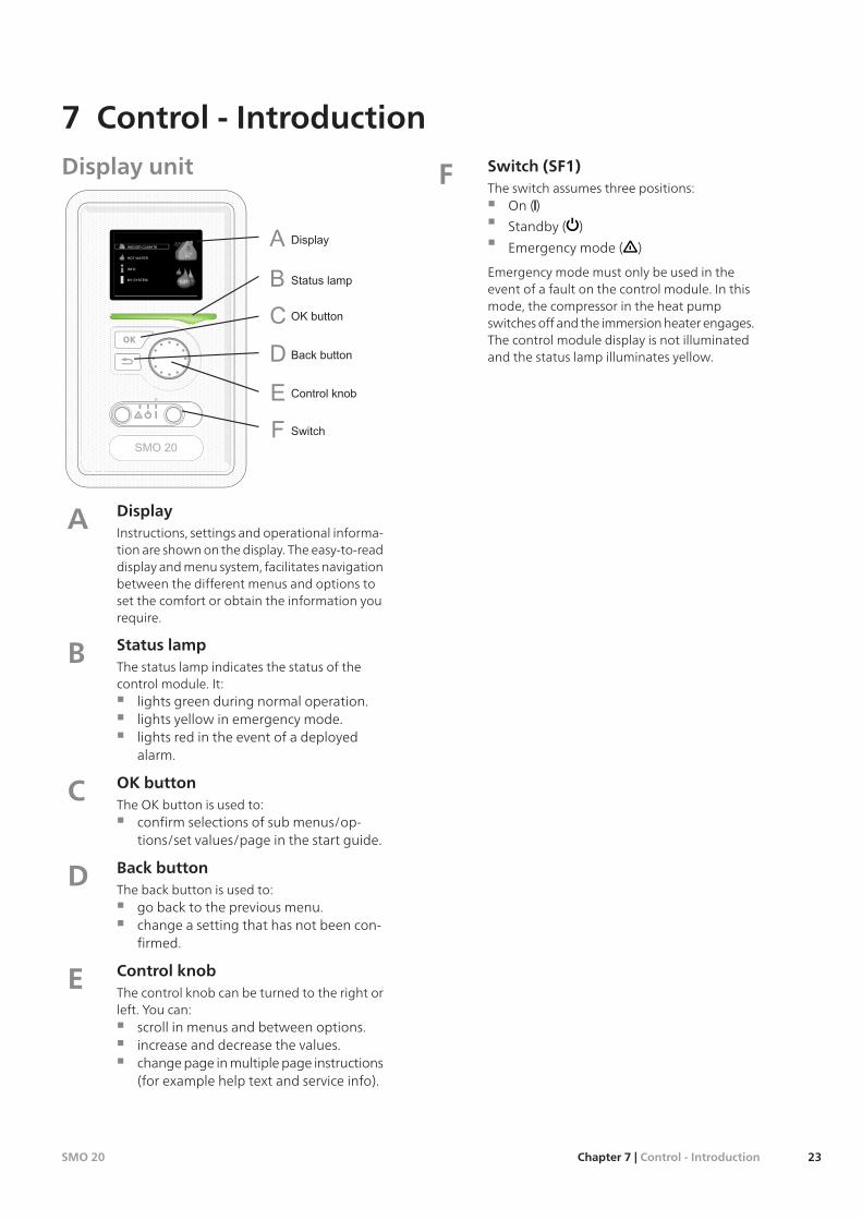
Display unit
DisplayInstructions, settings and operational informa-tion are shown on the display. The easy-to-readdisplay and menu system, facilitates navigationbetween the different menus and options toset the comfort or obtain the information yourequire.
A
Status lampThe status lamp indicates the status of thecontrol module. It:
lights green during normal operation.lights yellow in emergency mode.lights red in the event of a deployedalarm.
B
OK buttonThe OK button is used to:
confirm selections of sub menus/op-tions/set values/page in the start guide.
C
Back buttonThe back button is used to:
go back to the previous menu.change a setting that has not been con-firmed.
D
Control knobThe control knob can be turned to the right orleft. You can:
scroll in menus and between options.increase and decrease the values.change page in multiple page instructions(for example help text and service info).
E
Switch (SF1)The switch assumes three positions:
On ()
Standby ( )
Emergency mode ( )
Emergency mode must only be used in theevent of a fault on the control module. In thismode, the compressor in the heat pumpswitches off and the immersion heater engages.The control module display is not illuminatedand the status lamp illuminates yellow.
F
23Chapter 7 | Control - IntroductionSMO 20
7 Control - Introduction
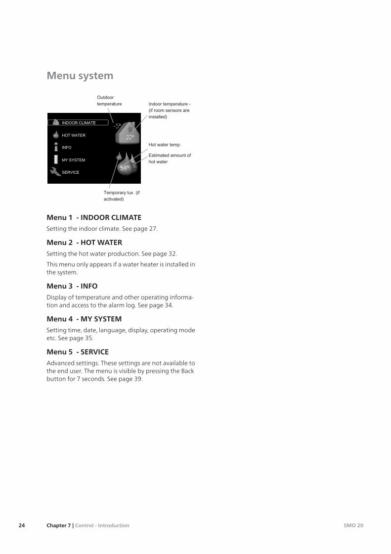
Menu system
Menu 1 - INDOOR CLIMATE
Setting the indoor climate. See page 27.
Menu 2 - HOT WATER
Setting the hot water production. See page 32.
This menu only appears if a water heater is installed inthe system.
Menu 3 - INFO
Display of temperature and other operating informa-tion and access to the alarm log. See page 34.
Menu 4 - MY SYSTEM
Setting time, date, language, display, operating modeetc. See page 35.
Menu 5 - SERVICE
Advanced settings. These settings are not available tothe end user. The menu is visible by pressing the Backbutton for 7 seconds. See page 39.
SMO 20Chapter 7 | Control - Introduction24
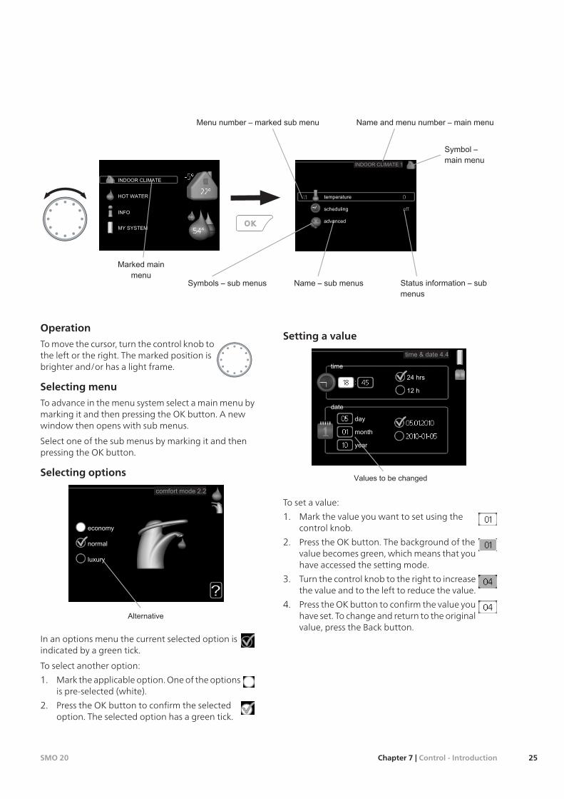
Operation
To move the cursor, turn the control knob tothe left or the right. The marked position isbrighter and/or has a light frame.
Selecting menu
To advance in the menu system select a main menu bymarking it and then pressing the OK button. A newwindow then opens with sub menus.
Select one of the sub menus by marking it and thenpressing the OK button.
Selecting options
In an options menu the current selected option isindicated by a green tick.
To select another option:
1. Mark the applicable option. One of the optionsis pre-selected (white).
2. Press the OK button to confirm the selectedoption. The selected option has a green tick.
Setting a value
To set a value:
1. Mark the value you want to set using thecontrol knob.
2. Press the OK button. The background of thevalue becomes green, which means that youhave accessed the setting mode.
3. Turn the control knob to the right to increasethe value and to the left to reduce the value.
4. Press the OK button to confirm the value youhave set. To change and return to the originalvalue, press the Back button.
25Chapter 7 | Control - IntroductionSMO 20
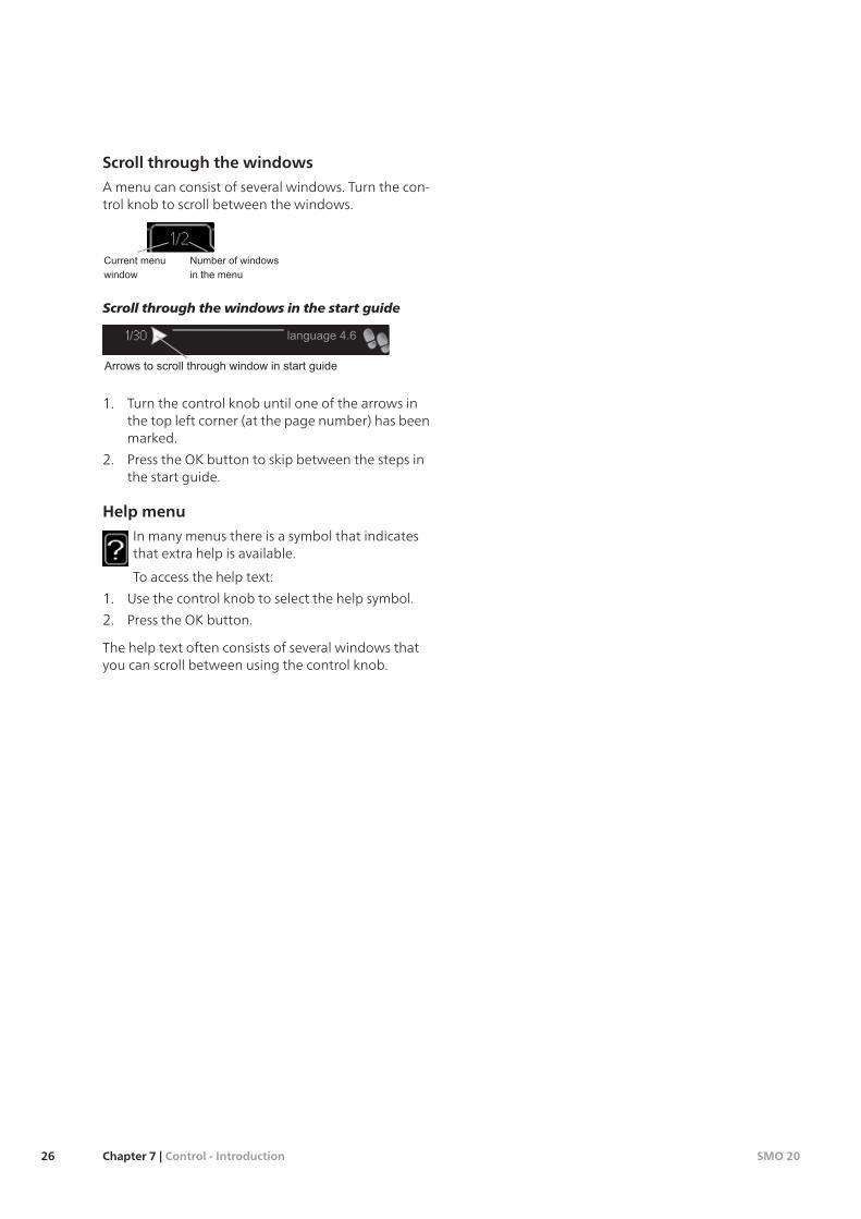
Scroll through the windows
A menu can consist of several windows. Turn the con-trol knob to scroll between the windows.
Scroll through the windows in the start guide
1. Turn the control knob until one of the arrows inthe top left corner (at the page number) has beenmarked.
2. Press the OK button to skip between the steps inthe start guide.
Help menu
In many menus there is a symbol that indicatesthat extra help is available.
To access the help text:
1. Use the control knob to select the help symbol.
2. Press the OK button.
The help text often consists of several windows thatyou can scroll between using the control knob.
SMO 20Chapter 7 | Control - Introduction26
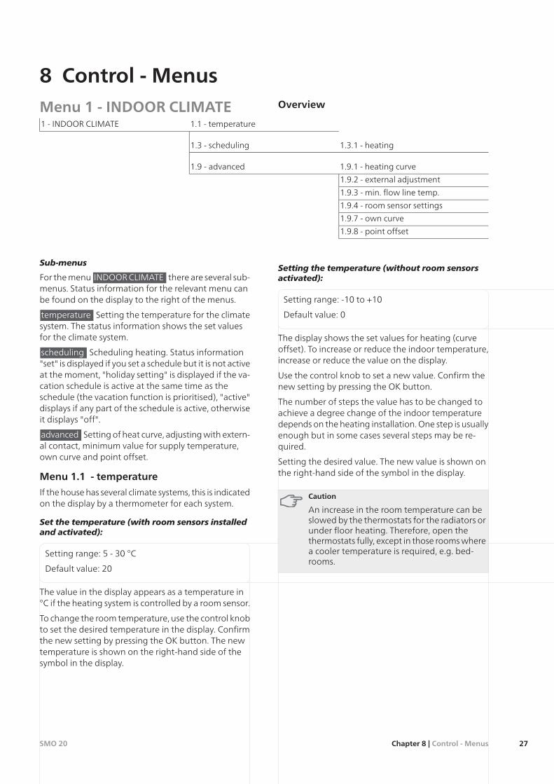
Menu 1 - INDOOR CLIMATE Overview
1.1 - temperature1 - INDOOR CLIMATE
1.3.1 - heating1.3 - scheduling
1.9.1 - heating curve1.9 - advanced
1.9.2 - external adjustment
1.9.3 - min. flow line temp.
1.9.4 - room sensor settings
1.9.7 - own curve
1.9.8 - point offset
Sub-menus
For the menu INDOOR CLIMATE there are several sub-menus. Status information for the relevant menu canbe found on the display to the right of the menus.
temperature Setting the temperature for the climatesystem. The status information shows the set valuesfor the climate system.
scheduling Scheduling heating. Status information"set" is displayed if you set a schedule but it is not activeat the moment, "holiday setting" is displayed if the va-cation schedule is active at the same time as theschedule (the vacation function is prioritised), "active"displays if any part of the schedule is active, otherwiseit displays "off".
advanced Setting of heat curve, adjusting with extern-al contact, minimum value for supply temperature,own curve and point offset.
Menu 1.1 - temperature
If the house has several climate systems, this is indicatedon the display by a thermometer for each system.
Set the temperature (with room sensors installedand activated):
Setting range: 5 - 30 °C
Default value: 20
The value in the display appears as a temperature in°C if the heating system is controlled by a room sensor.
To change the room temperature, use the control knobto set the desired temperature in the display. Confirmthe new setting by pressing the OK button. The newtemperature is shown on the right-hand side of thesymbol in the display.
Setting the temperature (without room sensorsactivated):
Setting range: -10 to +10
Default value: 0
The display shows the set values for heating (curveoffset). To increase or reduce the indoor temperature,increase or reduce the value on the display.
Use the control knob to set a new value. Confirm thenew setting by pressing the OK button.
The number of steps the value has to be changed toachieve a degree change of the indoor temperaturedepends on the heating installation. One step is usuallyenough but in some cases several steps may be re-quired.
Setting the desired value. The new value is shown onthe right-hand side of the symbol in the display.
Caution
An increase in the room temperature can beslowed by the thermostats for the radiators orunder floor heating. Therefore, open thethermostats fully, except in those rooms wherea cooler temperature is required, e.g. bed-rooms.
27Chapter 8 | Control - MenusSMO 20
8 Control - Menus
TIP
Wait 24 hours before making a new setting,so that the room temperature has time tostabilise.
If it is cold outdoors and the room temperatureis too low, increase the curve slope in menu1.9.1 by one increment.
If it is cold outdoors and the room temperatureis too high, lower the curve slope menu 1.9.1by one increment.
If it is warm outdoors and the room temperat-ure is too low, increase the value in menu 1.1by one increment.
If it is warm outdoors and the room temperat-ure is too high, reduce the value in menu 1.1by one increment.
Menu 1.3 - scheduling
In the menu scheduling indoor climate (heating) isscheduled for each weekday.
You can also schedule a longer period during a selectedperiod (vacation) in menu 4.7.
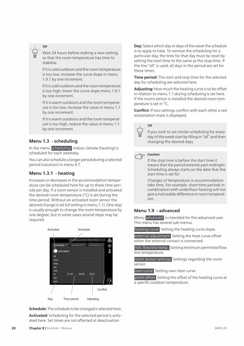
Menu 1.3.1 - heating
Increases or decreases in the accommodation temper-ature can be scheduled here for up to three time peri-ods per day. If a room sensor is installed and activatedthe desired room temperature (°C) is set during thetime period. Without an activated room sensor thedesired change is set (of setting in menu 1.1). One stepis usually enough to change the room temperature byone degree, but in some cases several steps may berequired.
Schedule: The schedule to be changed is selected here.
Activated: Scheduling for the selected period is activ-ated here. Set times are not affected at deactivation.
Day: Select which day or days of the week the scheduleis to apply to here. To remove the scheduling for aparticular day, the time for that day must be reset bysetting the start time to the same as the stop time. Ifthe line "all" is used, all days in the period are set forthese times.
Time period: The start and stop time for the selectedday for scheduling are selected here.
Adjusting:How much the heating curve is to be offsetin relation to menu 1.1 during scheduling is set here.If the rooms sensor is installed the desired room tem-perature is set in °C.
Conflict: If two settings conflict with each other a redexclamation mark is displayed.
TIP
If you wish to set similar scheduling for everyday of the week start by filling in “all” and thenchanging the desired days.
Caution
If the stop time is before the start time itmeans that the period extends past midnight.Scheduling always starts on the date that thestart time is set for.
Changes of temperature in accommodationtake time. For example, short time periods incombination with underfloor heating will notgive a noticeable difference in room temperat-ure.
Menu 1.9 - advanced
Menu advanced is intended for the advanced user.This menu has several sub-menus.
heating curve Setting the heating curve slope.
external adjustment Setting the heat curve offsetwhen the external contact is connected.
min. flow line temp. Setting minimum permitted flowline temperature.
room sensor settings Settings regarding the roomsensor.
own curve Setting own heat curve.
point offset Setting the offset of the heating curve ata specific outdoor temperature.
SMO 20Chapter 8 | Control - Menus28
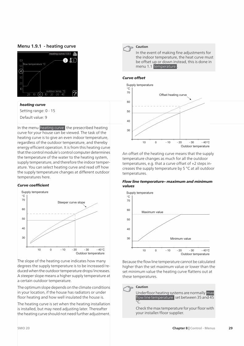
Menu 1.9.1 - heating curve
heating curve
Setting range: 0 - 15
Default value: 9
In the menu heating curve the presecribed heatingcurve for your house can be viewed. The task of theheating curve is to give an even indoor temperature,regardless of the outdoor temperature, and therebyenergy efficient operation. It is from this heating curvethat the control module’s control computer determinesthe temperature of the water to the heating system,supply temperature, and therefore the indoor temper-ature. You can select heating curve and read off howthe supply temperature changes at different outdoortemperatures here.
Curve coefficient
30
40
50
60
70°C
- 40°CUTETEMPERATUR
- 10010 - 20 - 30
Brantare kurvlutning
The slope of the heating curve indicates how manydegrees the supply temperature is to be increased/re-duced when the outdoor temperature drops/increases.A steeper slope means a higher supply temperature ata certain outdoor temperature.
The optimum slope depends on the climate conditionsin your location, if the house has radiators or underfloor heating and how well insulated the house is.
The heating curve is set when the heating installationis installed, but may need adjusting later. Thereafterthe heating curve should not need further adjustment.
Caution
In the event of making fine adjustments forthe indoor temperature, the heat curve mustbe offset up or down instead, this is done inmenu 1.1 temperature .
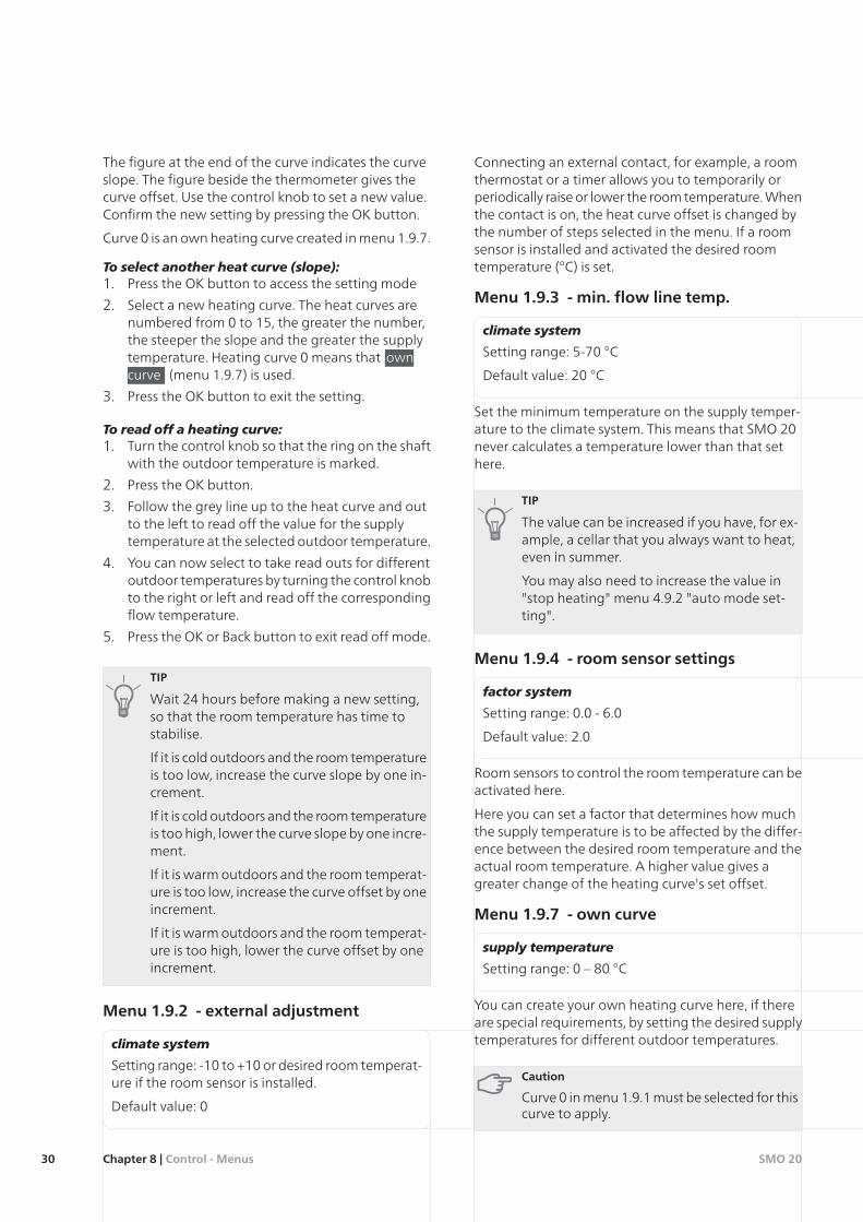
Curve offset
30
40
50
60
70°C
- 40°CUTETEMPERATUR
- 10010 - 20 - 30
Förskjuten värmekurva
An offset of the heating curve means that the supplytemperature changes as much for all the outdoortemperatures, e.g. that a curve offset of +2 steps in-creases the supply temperature by 5 °C at all outdoortemperatures.
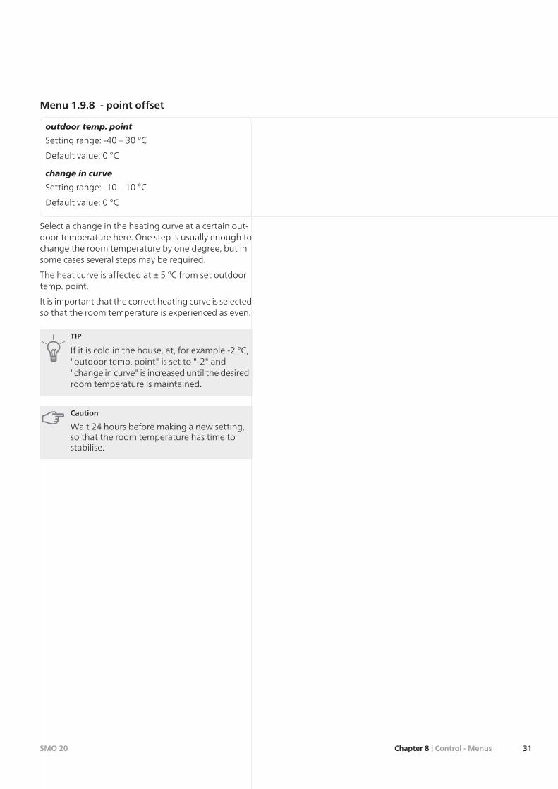
Flow line temperature– maximum and minimumvalues
30
40
50
60
70°C
- 40°CUTETEMPERATUR
- 10010 - 20 - 30
Maximivärde
Minimivärde
Because the flow line temperature cannot be calculatedhigher than the set maximum value or lower than theset minimum value the heating curve flattens out atthese temperatures.
Caution
Underfloor heating systems are normally maxflow line temperature set between 35 and 45°C.
Check the max temperature for your floor withyour installer/floor supplier.
29Chapter 8 | Control - MenusSMO 20
The figure at the end of the curve indicates the curveslope. The figure beside the thermometer gives thecurve offset. Use the control knob to set a new value.Confirm the new setting by pressing the OK button.
Curve 0 is an own heating curve created in menu 1.9.7.
To select another heat curve (slope):1. Press the OK button to access the setting mode
2. Select a new heating curve. The heat curves arenumbered from 0 to 15, the greater the number,the steeper the slope and the greater the supplytemperature. Heating curve 0 means that owncurve (menu 1.9.7) is used.
3. Press the OK button to exit the setting.
To read off a heating curve:1. Turn the control knob so that the ring on the shaft
with the outdoor temperature is marked.
2. Press the OK button.
3. Follow the grey line up to the heat curve and outto the left to read off the value for the supplytemperature at the selected outdoor temperature.
4. You can now select to take read outs for differentoutdoor temperatures by turning the control knobto the right or left and read off the correspondingflow temperature.
5. Press the OK or Back button to exit read off mode.
TIP
Wait 24 hours before making a new setting,so that the room temperature has time tostabilise.
If it is cold outdoors and the room temperatureis too low, increase the curve slope by one in-crement.
If it is cold outdoors and the room temperatureis too high, lower the curve slope by one incre-ment.
If it is warm outdoors and the room temperat-ure is too low, increase the curve offset by oneincrement.
If it is warm outdoors and the room temperat-ure is too high, lower the curve offset by oneincrement.
Menu 1.9.2 - external adjustment
climate system
Setting range: -10 to +10 or desired room temperat-ure if the room sensor is installed.
Default value: 0
Connecting an external contact, for example, a roomthermostat or a timer allows you to temporarily orperiodically raise or lower the room temperature. Whenthe contact is on, the heat curve offset is changed bythe number of steps selected in the menu. If a roomsensor is installed and activated the desired roomtemperature (°C) is set.
Menu 1.9.3 - min. flow line temp.
climate system
Setting range: 5-70 °C
Default value: 20 °C
Set the minimum temperature on the supply temper-ature to the climate system. This means that SMO 20never calculates a temperature lower than that sethere.
TIP
The value can be increased if you have, for ex-ample, a cellar that you always want to heat,even in summer.
You may also need to increase the value in"stop heating" menu 4.9.2 "auto mode set-ting".
Menu 1.9.4 - room sensor settings
factor system
Setting range: 0.0 - 6.0
Default value: 2.0
Room sensors to control the room temperature can beactivated here.
Here you can set a factor that determines how muchthe supply temperature is to be affected by the differ-ence between the desired room temperature and theactual room temperature. A higher value gives agreater change of the heating curve's set offset.
Menu 1.9.7 - own curve
supply temperature
Setting range: 0 – 80 °C
You can create your own heating curve here, if thereare special requirements, by setting the desired supplytemperatures for different outdoor temperatures.
Caution
Curve 0 in menu 1.9.1 must be selected for thiscurve to apply.
SMO 20Chapter 8 | Control - Menus30
Menu 1.9.8 - point offset
outdoor temp. point
Setting range: -40 – 30 °C
Default value: 0 °C
change in curve
Setting range: -10 – 10 °C
Default value: 0 °C
Select a change in the heating curve at a certain out-door temperature here. One step is usually enough tochange the room temperature by one degree, but insome cases several steps may be required.
The heat curve is affected at ± 5 °C from set outdoortemp. point.
It is important that the correct heating curve is selectedso that the room temperature is experienced as even.
TIP
If it is cold in the house, at, for example -2 °C,"outdoor temp. point" is set to "-2" and"change in curve" is increased until the desiredroom temperature is maintained.
Caution
Wait 24 hours before making a new setting,so that the room temperature has time tostabilise.
31Chapter 8 | Control - MenusSMO 20
Menu 2 - HOT WATER Overview
2.1 - temporary lux2 - HOT WATER *
2.2 - comfort mode
2.3 - scheduling
2.9.1 - periodic increases2.9 - advanced
* Accessory needed.
Sub-menus
This menu only appears if a water heater is docked tothe heat pump.
For the menu HOT WATER there are several sub-menus. Status information for the relevant menu canbe found on the display to the right of the menus.
temporary lux Activation of temporary increase in thehot water temperature. Status information displays“off" or what length of time of the temporary temper-ature increase remains.
comfort mode Setting hot water comfort. The statusinformation displays what mode is selected, "economy","normal" or "luxury".
scheduling Scheduling hot water comfort. Status in-formation "set" displays if any part of the schedule isactive at present, "holiday setting" displays if vacationsetting is in progress (menu 4.7), otherwise it displays"off".
advanced Setting periodic increase in the hot watertemperature.
Menu 2.1 - temporary lux
Setting range: 3, 6 and 12 hours and mode "off"
Default value: "off"
When hot water requirement has temporarily increasedthis menu can be used to select an increase in the hotwater temperature to lux mode for a selectable time.
Caution
If comfort mode "luxury" is selected in menu2.2 no further increase can be carried out.
The function is activated immediately when a timeperiod is selected and confirmed using the OK button.The remaining time for the selected setting is shownto the right.
When the time has run out SMO 20 returns to themode set in menu 2.2.
Select “off" to switch off temporary lux .
Menu 2.2 - comfort mode
Setting range: economy, normal, luxury
Default value: normal
The difference between the selectable modes is thetemperature of the hot tap water. Higher temperaturemeans that the hot water lasts longer.
economy: This mode gives less hot water than theother, but is more economical. This mode can be usedin smaller households with a small hot water require-ment.
normal: Normal mode gives a larger amount of hotwater and is suitable for most households.
luxury: Lux mode gives the greatest possible amountof hot water. In this mode, the immersion heater, aswell as the compressor, is used to heat hot water, whichmay increase operating costs.
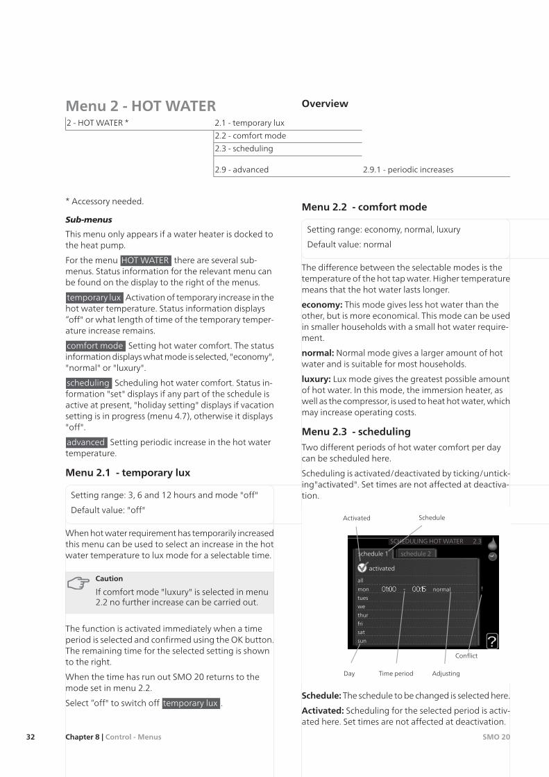
Menu 2.3 - scheduling
Two different periods of hot water comfort per daycan be scheduled here.
Scheduling is activated/deactivated by ticking/untick-ing"activated". Set times are not affected at deactiva-tion.
all
mon
tues
we
thur
fri
sat
sun
activated
schedule 2schedule 1
SCHEDULING HOT WATER 2.3
normal
Time period AdjustingDay
Activated Schedule
Conflict
Schedule: The schedule to be changed is selected here.
Activated: Scheduling for the selected period is activ-ated here. Set times are not affected at deactivation.
SMO 20Chapter 8 | Control - Menus32
Day: Select which day or days of the week the scheduleis to apply to here. To remove the scheduling for aparticular day, the time for that day must be reset bysetting the start time to the same as the stop time. Ifthe line "all" is used, all days in the period are set forthese times.
Time period: The start and stop time for the selectedday for scheduling are selected here.
Adjusting: Set the hot water comfort that is to applyduring scheduling here.
Conflict: If two settings conflict with each other a redexclamation mark is displayed.
TIP
If you wish to set similar scheduling for everyday of the week start by filling in “all” and thenchanging the desired days.
Caution
If the stop time is earlier in the day than thestart time it means that the period extendspast midnight.
Scheduling always starts on the date that thestart time is set for.
Menu 2.9 - advanced
Menu advanced is intended for the advanced user.This menu has several sub-menus.
Menu 2.9.1 - periodic increases
period
Setting range: 1 - 90 days
Default value: 14 days
start time
Setting range: 00:00 - 23:00
Default value: 00:00
To prevent bacterial growth in the water heater, theheat pump and any additional heat can increase thehot water temperature for a short time at regular inter-vals.
The length of time between increases can be selectedhere. The time can be set between 1 and 90 days.Factory setting is 14 days. Untick "activated" to switchoff the function.
33Chapter 8 | Control - MenusSMO 20
Menu 3 - INFO Overview
3.1 - service info3 - INFO
3.2 - compressor info
3.3 - add. heat info
3.4 - alarm log
3.5 - indoor temp. log
Sub-menus
For the menu INFO there are several sub-menus. Nosettings can be made in these menus, they just displayinformation. Status information for the relevant menucan be found on the display to the right of the menus.
service info shows temperature levels and settings inthe installation.
compressor info shows operating times, number ofstarts etc for the compressor in the heat pump.
add. heat info displays information about the addi-tion’s operating times etc.
alarm log shows the latest alarms.
indoor temp. log the average temperature indoorsweek by week during the past year.
Menu 3.1 - service info
Information about the actual operating status of theinstallation (e.g. current temperatures etc.) can be ob-tained here. No changes can be made.
The information is on several pages. Turn the controlknob to scroll between the pages.
Symbols in this menu:
HeatingCompressor
Hot waterAddition
Menu 3.2 - compressor info
Information about the compressor’s operating statusand statistics can be obtained here. No changes canbe made.
The information is on several pages. Turn the controlknob to scroll between the pages.
Menu 3.3 - add. heat info
Information about the additional heat settings, operat-ing status and statistics can be obtained here. Nochanges can be made.
The information is on several pages. Turn the controlknob to scroll between the pages.
Menu 3.4 - alarm log
To facilitate fault-finding the installation's operatingstatus at alarm alerts is stored here. You can see inform-ation for the 10 most recent alarms.
To view the run status in the event of an alarm, markthe alarm and press the OK button.
Menu 3.5 - indoor temp. log
Here you can see the average temperature indoorsweek by week during the past year. The dotted lineindicates the annual average temperature.
The average outdoor temperature is only shown if aroom temperature sensor/room unit is installed.
To read off an average temperature1. Turn the control knob so that the ring on the shaft
with the week number is marked.
2. Press the OK button.
3. Follow the grey line up to the graph and out to theleft to read off the average indoor temperature atthe selected week.
4. You can now select to take read outs for differentweeks by turning the control knob to the right orleft and read off the average temperature.
5. Press the OK or Back button to exit read off mode.
SMO 20Chapter 8 | Control - Menus34
Menu 4 - MY SYSTEM Overview
4.1.5 - SG Ready4.1 - plus functions *4 - MY SYSTEM
4.2 - op. mode
4.4 - time & date
4.6 - language
4.7 - holiday setting
4.9.1 - op. prioritisation4.9 - advanced
4.9.2 - auto mode setting
4.9.3 - degree minute setting
4.9.4 - factory setting user
4.9.5 - schedule blocking
4.9.6 - schedule silent mode
Sub-menus
For the menu MY SYSTEM there are several sub-menus. Status information for the relevant menu canbe found on the display to the right of the menus.
plus functions Settings applying to any installed extrafunctions in the heating system.
op. mode Activation of manual or automatic operat-ing mode. The status information shows the selectedoperating mode.
time & date Setting current time and date.
language Select the language for the display here.The status information shows the selected language.
holiday setting Vacation scheduling heating and hotwater comfort. Status information "set" is displayed ifyou set a vacation schedule but it is not active at themoment, "active" is displayed if any part of the vacationschedule is active, otherwise it displays " off".
advanced Settings of control module work mode.
Menu 4.1 - plus functions
Settings for any additional functions installed in SMO20 can be made in the sub menus.
Menu 4.1.5 - SG Ready
This function can only be used in mains networks thatsupport the "SG Ready"-standard (Germany).
Make settings for the function "SG Ready" here.
affect room temperature
Here you set whether room temperature should beaffected when activating "SG Ready".
With low price mode of "SG Ready" the parallel offsetof the indoor temperature is increased by "+1". If aroom sensor is installed and activated, the desired roomtemperature increases by 1 °C.
With over capacity mode of "SG Ready" the paralleloffset for the indoor temperature is increased by"+2".If a room sensor is installed and activated, the desiredroom temperature increases by 2 °C.
affect hot water
Here you set whether the temperature of the hot watershould be affected when activating "SG Ready".
With low price mode on "SG Ready" the stop temper-ature of the hot water is set as high as possible at onlycompressor operation (immersion heater not permit-ted).
With over capacity mode of "SG Ready" the hot wateris set to "luxury" (immersion heater permitted).
NOTE
The function must be connected to two AUXinputs and activated in menu 5.4.
Menu 4.2 - op. mode
op. mode
Setting range: auto, manual, add. heat only
Default value: auto
functions
Setting range: compressor, addition, heating
The control module operating mode is usually set to"auto". It is also possible to set the control module to"add. heat only", when only additional heat is used, or"manual" and then select what functions are to bepermitted.
Change the operating mode by marking the desiredmode and pressing the OK button. When an operatingmode is selected it shows what in the control moduleis permitted (crossed out = not permitted) and select-
35Chapter 8 | Control - MenusSMO 20
able alternatives to the right. To select selectablefunctions that are permitted or not you mark thefunction using the control knob and press the OK but-ton.
Operating mode auto
In this operating mode the control module automatic-ally selects what functions are permitted.
Operating mode manual
In this operating mode you can select what functionsare permitted. You cannot deselect "compressor" inmanual mode.
Operating mode add. heat only
In this operating mode the compressor is not activeand only additional heating is used.
Caution
If you choose mode "add. heat only" the com-pressor is deselected and there is a higher op-erating cost.
Caution
You cannot change from only additional heatif you do not have a heat pump connected(see menu 5.2.2).
Functions
"compressor" is that which produces heating and hotwater for the accommodation. If "compressor" isdeselected, a symbol is displayed in the main menu onthe symbol for the control module. You cannot deselect"compressor" in manual mode.
"addition" is what helps the compressor to heat theaccommodation and/or the hot water when it cannotmanage the whole requirement alone.
"heating" means that you get heat in the accommod-ation. You can deselect the function when you do notwish to have heating running.
Menu 4.4 - time & date
Set time and date and display mode here.
Menu 4.6 - language
Choose the language that you want the informationto be displayed in here.
Menu 4.7 - holiday setting
If a room sensor is installed and activated the desiredroom temperature (°C) is set during the time period.This setting applies to all climate systems with roomsensors.
If a room sensor is not activated, the desired offset ofthe heating curve is set. This setting applies to all cli-mate systems without room sensors. One step is usuallyenough to change the room temperature by one de-gree, but in some cases several steps may be required.
Vacation scheduling starts at 00:00 on the start dateand stops at 23:59 on the stop date.
TIP
Complete holiday setting about a day beforeyour return so that room temperature and hotwater have time to regain usual levels.
TIP
Set the vacation setting in advance and activ-ate just before departure in order to maintainthe comfort.
Caution
If you choose to switch off hot water produc-tion during the vacation “periodic increases"(preventing bacterial growth) are blockedduring this time. "periodic increases" startedin conjunction with the vacation setting beingcompleted.
Menu 4.9 - advanced
Menu advanced is intended for the advanced user.This menu has several sub-menus.
Menu 4.9.1 - op. prioritisation
op. prioritisation
Setting range: 0 to 180 min
Default value: 20 min
The indicator marks where in the cycle the installationis.
If 0 minutes is selected it means that requirement isnot prioritised, but will only be activated when thereis no other requirement.
SMO 20Chapter 8 | Control - Menus36
Menu 4.9.2 - auto mode setting
stop heating
Setting range: -20 – 40 °C
Default values: 20
stop additional heat
Setting range: -25 – 40 °C
Default values: 15
filtering time
Setting range: 0 – 48 h
Default value: 24 h
When the operating mode is set to "auto", the controlmodule selects when start and stop of additional heatand heat production is permitted, dependent on theaverage outdoor temperature.
Select the average outdoor temperatures in this menu.
You can also set the time over which (filtering time)the average temperature is calculated. If you select 0,the present outdoor temperature is used.
Caution
It cannot be set "stop additional heat" higherthan "stop heating".
Menu 4.9.3 - degree minute setting
current value
Setting range: -3000 – 3000
start compressor
Setting range: -1000 – -30
Default value: -60
start diff additional heat
Setting range: 100 – 1000
Default value: 400
diff. between additional steps
Setting range: 0 – 1000
Default value: 30
Degree minutes are a measurement of the currentheating requirement in the house and determine whenthe compressor respectively additional heat willstart/stop.
Caution
Higher value on "start compressor" gives morecompressor starts, which increases wear in thecompressor. Too low value can give unevenindoor temperatures.
Menu 4.9.4 - factory setting user
All settings that are available to the user (includingadvanced menus) can be reset to default values here.
Caution
After factory setting, personal settings such asheating curves must be reset.
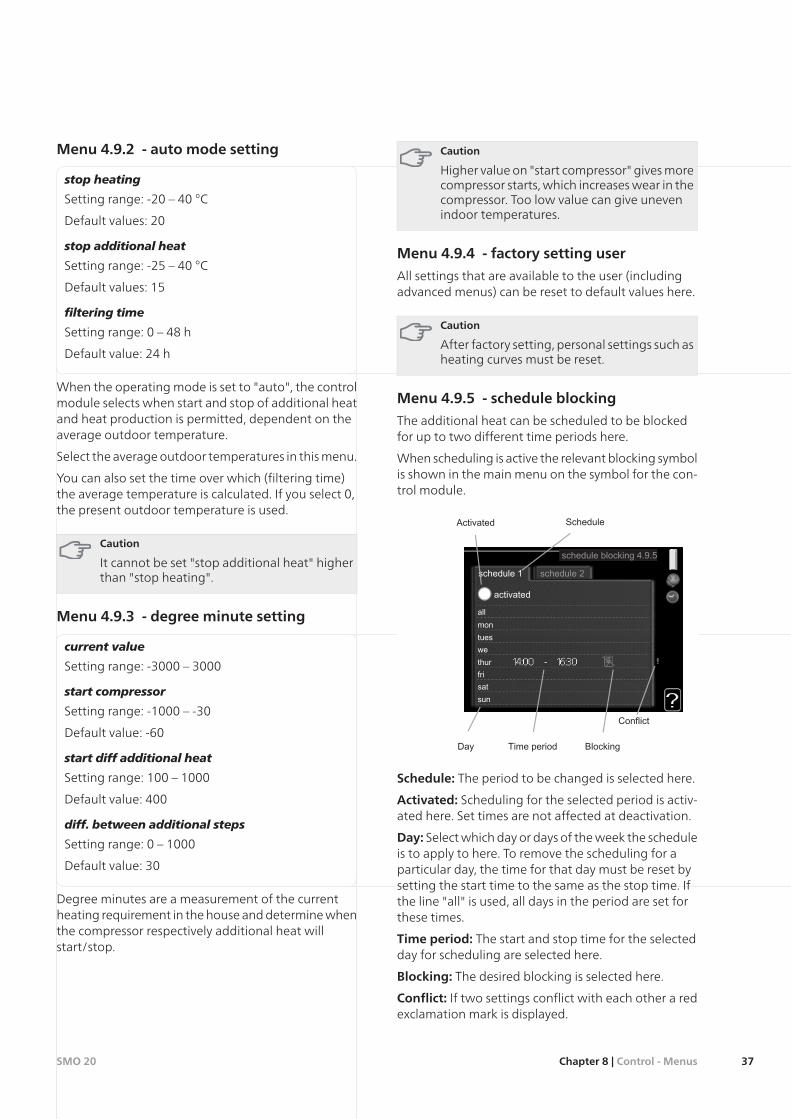
Menu 4.9.5 - schedule blocking
The additional heat can be scheduled to be blockedfor up to two different time periods here.
When scheduling is active the relevant blocking symbolis shown in the main menu on the symbol for the con-trol module.
Schedule: The period to be changed is selected here.
Activated: Scheduling for the selected period is activ-ated here. Set times are not affected at deactivation.
Day: Select which day or days of the week the scheduleis to apply to here. To remove the scheduling for aparticular day, the time for that day must be reset bysetting the start time to the same as the stop time. Ifthe line "all" is used, all days in the period are set forthese times.
Time period: The start and stop time for the selectedday for scheduling are selected here.
Blocking: The desired blocking is selected here.
Conflict: If two settings conflict with each other a redexclamation mark is displayed.
37Chapter 8 | Control - MenusSMO 20
Blocking the compressor in the outdoor unit.
Blocking additional heat.
TIP
If you wish to set similar scheduling for everyday of the week start by filling in “all” and thenchanging the desired days.
Caution
If the stop time is before the start time itmeans that the period extends past midnight.
Scheduling always starts on the date that thestart time is set for.
Caution
Long term blocking can cause reduced comfortand operating economy.
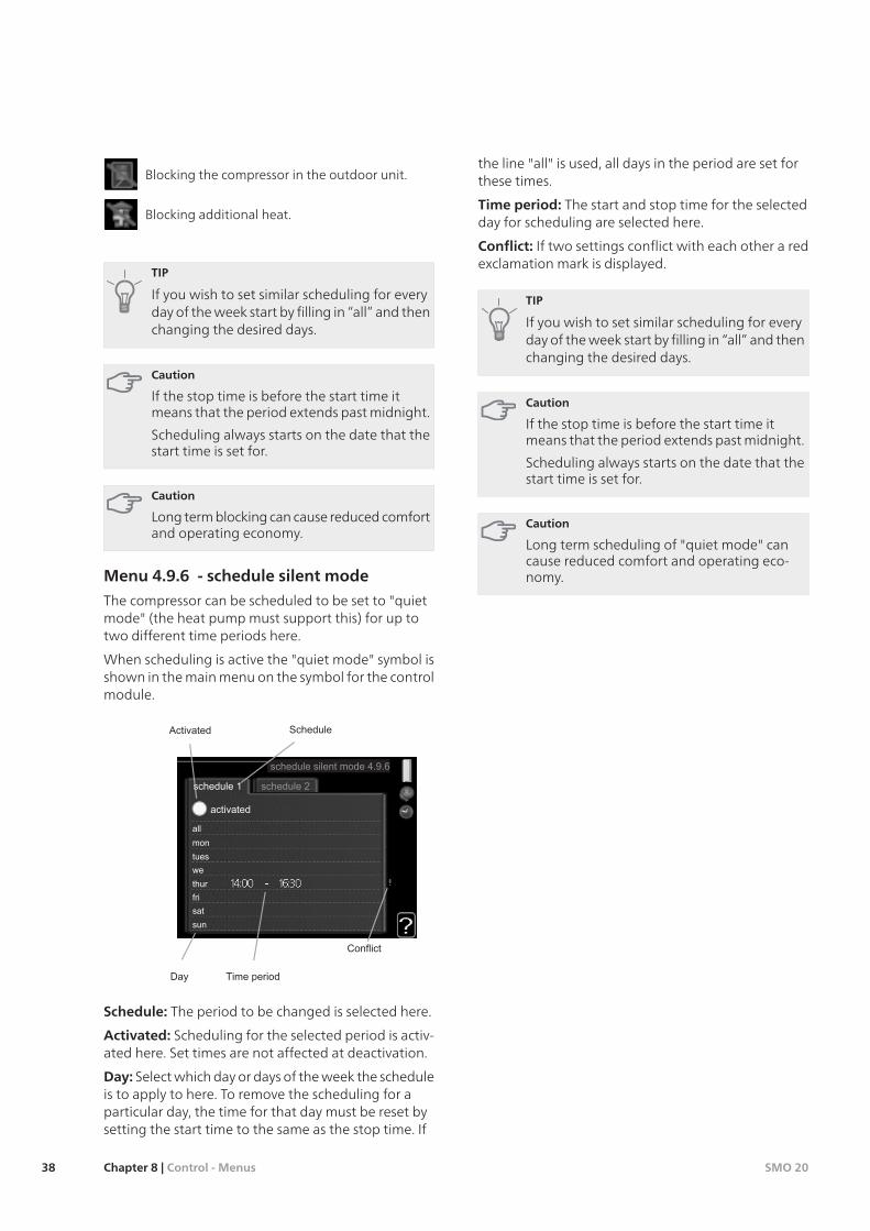
Menu 4.9.6 - schedule silent mode
The compressor can be scheduled to be set to "quietmode" (the heat pump must support this) for up totwo different time periods here.
When scheduling is active the "quiet mode" symbol isshown in the main menu on the symbol for the controlmodule.
Schedule: The period to be changed is selected here.
Activated: Scheduling for the selected period is activ-ated here. Set times are not affected at deactivation.
Day: Select which day or days of the week the scheduleis to apply to here. To remove the scheduling for aparticular day, the time for that day must be reset bysetting the start time to the same as the stop time. If
the line "all" is used, all days in the period are set forthese times.
Time period: The start and stop time for the selectedday for scheduling are selected here.
Conflict: If two settings conflict with each other a redexclamation mark is displayed.
TIP
If you wish to set similar scheduling for everyday of the week start by filling in “all” and thenchanging the desired days.
Caution
If the stop time is before the start time itmeans that the period extends past midnight.
Scheduling always starts on the date that thestart time is set for.
Caution
Long term scheduling of "quiet mode" cancause reduced comfort and operating eco-nomy.
SMO 20Chapter 8 | Control - Menus38
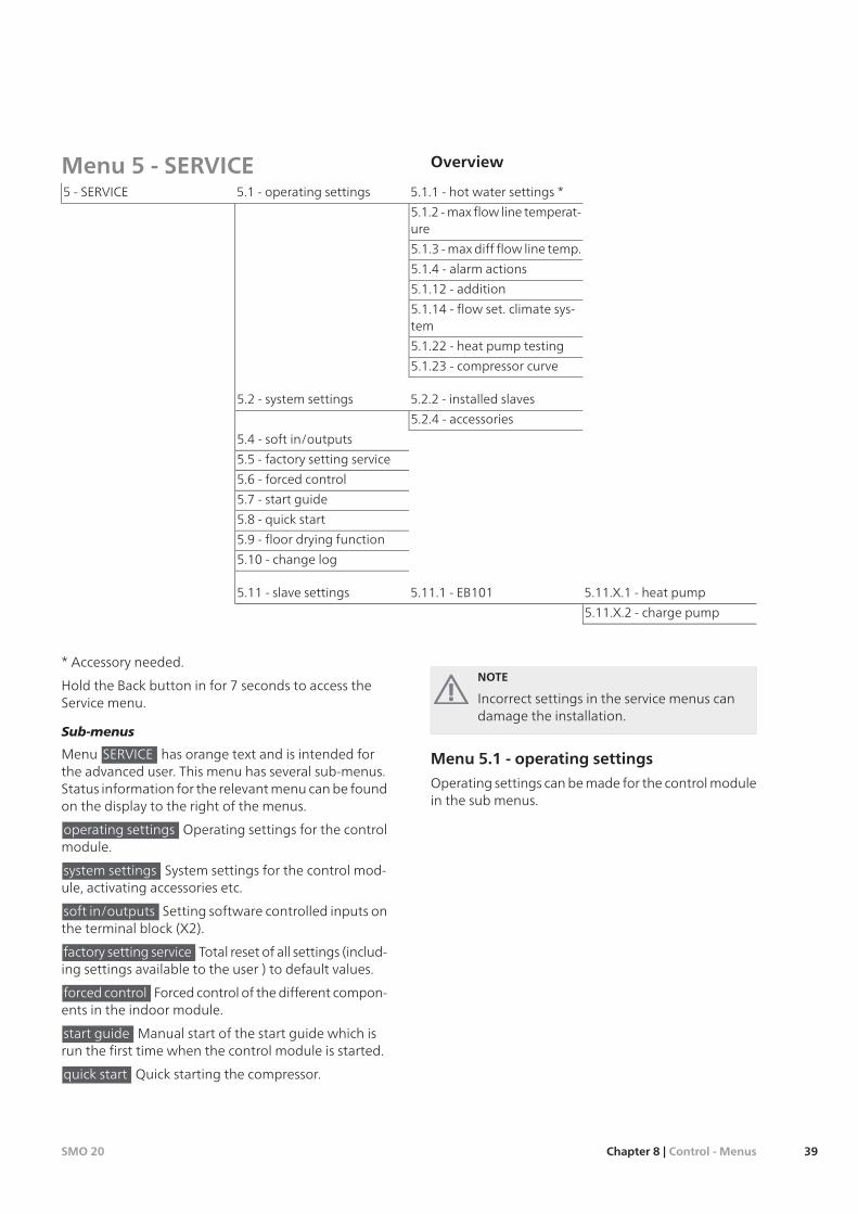
Menu 5 - SERVICE Overview
5.1.1 - hot water settings *5.1 - operating settings5 - SERVICE
5.1.2 - max flow line temperat-ure
5.1.3 - max diff flow line temp.
5.1.4 - alarm actions
5.1.12 - addition
5.1.14 - flow set. climate sys-tem
5.1.22 - heat pump testing
5.1.23 - compressor curve
5.2.2 - installed slaves5.2 - system settings
5.2.4 - accessories
5.4 - soft in/outputs
5.5 - factory setting service
5.6 - forced control
5.7 - start guide
5.8 - quick start
5.9 - floor drying function
5.10 - change log
5.11.X.1 - heat pump5.11.1 - EB1015.11 - slave settings
5.11.X.2 - charge pump
* Accessory needed.
Hold the Back button in for 7 seconds to access theService menu.
Sub-menus
Menu SERVICE has orange text and is intended forthe advanced user. This menu has several sub-menus.Status information for the relevant menu can be foundon the display to the right of the menus.
operating settings Operating settings for the controlmodule.
system settings System settings for the control mod-ule, activating accessories etc.
soft in/outputs Setting software controlled inputs onthe terminal block (X2).
factory setting service Total reset of all settings (includ-ing settings available to the user ) to default values.
forced control Forced control of the different compon-ents in the indoor module.
start guide Manual start of the start guide which isrun the first time when the control module is started.
quick start Quick starting the compressor.
NOTE
Incorrect settings in the service menus candamage the installation.
Menu 5.1 - operating settings
Operating settings can be made for the control modulein the sub menus.
39Chapter 8 | Control - MenusSMO 20
Menu 5.1.1 - hot water settings
economy
Setting range start temp. economy: 5 – 70 °C
Factory setting start temp. economy: 38 °C
Setting range stop temp. economy: 5 – 70 °C
Factory setting stop temp. economy: 43 °C
normal
Setting range start temp. normal: 5 – 70 °C
Factory setting start temp. normal: 45 °C
Setting range stop temp. normal: 5 – 70 °C
Factory setting stop temp. normal: 50 °C
luxury
Setting range start temp. lux: 5 – 70 °C
Factory setting start temp. lux: 47 °C
Setting range stop temp. lux: 5 – 70 °C
Factory setting stop temp. lux: 52 °C
stop temp. per. increase
Setting range: 55 – 70 °C
Default values: 55 °C
Here you set the start and stop temperature of the hotwater for the different comfort options in menu 2.2 aswell as the stop temperature for periodic increase inmenu 2.9.1.
Menu 5.1.2 - max flow line temperature
climate system
Setting range: 5-70 °C
Default value: 60 °C
Set the maximum supply temperature for the climatesystem here.
Caution
Underfloor heating systems are normally maxflow line temperature set between 35 and 45°C.
Check the max floor temperature with yourfloor supplier.
Menu 5.1.3 - max diff flow line temp.
max diff compressor
Setting range: 1 – 25 °C
Default value: 10 °C
max diff addition
Setting range: 1 – 24 °C
Default value: 7 °C
Here you set the maximum permitted differencebetween the calculated and actual supply temperatureduring compressor respectively add. heat mode.
max diff compressor
When the current supply temperature deviates fromthe set value compared to that calculated, the heatpump is forced to stop irrespective of the degree-minute value.
If the calculated supply temperature exceeds the cal-culated flow with set value, the degree minute valueis set to 0. The compressor in the heat pump stopswhen there is only a heating demand.
max diff addition
If "addition” is selected and activated in menu 4.2 andthe present supply temp exceeds the calculated withset value, the additional heat is forced to stop.
Menu 5.1.4 - alarm actions
Select if you want the control module to alert you thatthere is an alarm in the display here.
Caution
If no alarm action is selected, it can result inhigher energy consumption in the event of analarm.
Menu 5.1.12 - addition
max step
Setting range (binary stepping deactivated): 0 – 3
Setting range (binary stepping activated): 0 – 7
Default value: 3
fuse size
Setting range: 1 - 200 A
Default values: 16 A
Here you select whether the step controlled additionalheat is positioned before or after the reversing valvefor hot water charging (QN10). Step controlled addi-tional heat is for example an external electric boiler.
SMO 20Chapter 8 | Control - Menus40
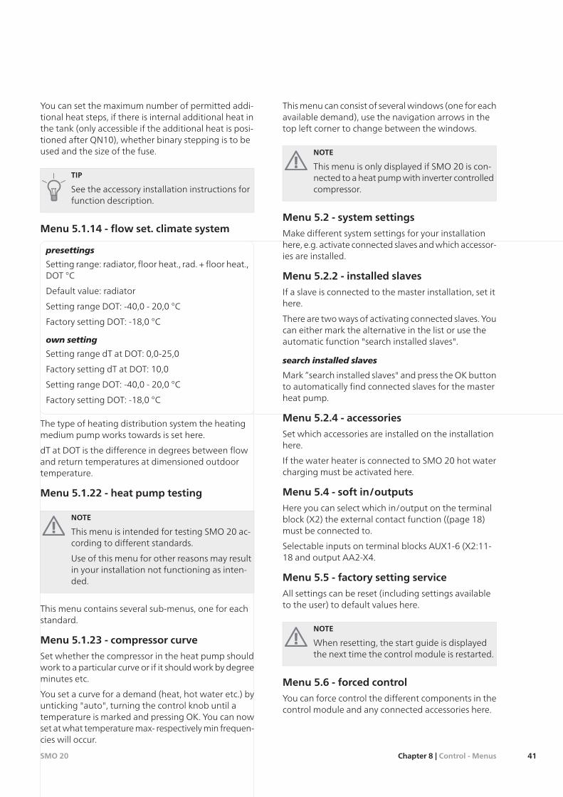
You can set the maximum number of permitted addi-tional heat steps, if there is internal additional heat inthe tank (only accessible if the additional heat is posi-tioned after QN10), whether binary stepping is to beused and the size of the fuse.
TIP
See the accessory installation instructions forfunction description.
Menu 5.1.14 - flow set. climate system
presettings
Setting range: radiator, floor heat., rad. + floor heat.,DOT °C
Default value: radiator
Setting range DOT: -40,0 - 20,0 °C
Factory setting DOT: -18,0 °C
own setting
Setting range dT at DOT: 0,0-25,0
Factory setting dT at DOT: 10,0
Setting range DOT: -40,0 - 20,0 °C
Factory setting DOT: -18,0 °C
The type of heating distribution system the heatingmedium pump works towards is set here.
dT at DOT is the difference in degrees between flowand return temperatures at dimensioned outdoortemperature.
Menu 5.1.22 - heat pump testing
NOTE
This menu is intended for testing SMO 20 ac-cording to different standards.
Use of this menu for other reasons may resultin your installation not functioning as inten-ded.
This menu contains several sub-menus, one for eachstandard.
Menu 5.1.23 - compressor curve
Set whether the compressor in the heat pump shouldwork to a particular curve or if it should work by degreeminutes etc.
You set a curve for a demand (heat, hot water etc.) byunticking "auto", turning the control knob until atemperature is marked and pressing OK. You can nowset at what temperature max- respectively min frequen-cies will occur.
This menu can consist of several windows (one for eachavailable demand), use the navigation arrows in thetop left corner to change between the windows.
NOTE
This menu is only displayed if SMO 20 is con-nected to a heat pump with inverter controlledcompressor.
Menu 5.2 - system settings
Make different system settings for your installationhere, e.g. activate connected slaves and which accessor-ies are installed.
Menu 5.2.2 - installed slaves
If a slave is connected to the master installation, set ithere.
There are two ways of activating connected slaves. Youcan either mark the alternative in the list or use theautomatic function "search installed slaves".
search installed slaves
Mark “search installed slaves" and press the OK buttonto automatically find connected slaves for the masterheat pump.
Menu 5.2.4 - accessories
Set which accessories are installed on the installationhere.
If the water heater is connected to SMO 20 hot watercharging must be activated here.
Menu 5.4 - soft in/outputs
Here you can select which in/output on the terminalblock (X2) the external contact function ((page 18)must be connected to.
Selectable inputs on terminal blocks AUX1-6 (X2:11-18 and output AA2-X4.
Menu 5.5 - factory setting service
All settings can be reset (including settings availableto the user) to default values here.
NOTE
When resetting, the start guide is displayedthe next time the control module is restarted.
Menu 5.6 - forced control
You can force control the different components in thecontrol module and any connected accessories here.
41Chapter 8 | Control - MenusSMO 20

Menu 5.7 - start guide
When the control module is started for the first timethe start guide starts automatically. Start it manuallyhere.
See page 22 for more information about the startguide.
Menu 5.8 - quick start
It is possible to start the compressor from here.
Caution
There must be a heating or hot water demandto start the compressor.
Caution
Do not quick start the compressor too manytimes in succession over a short period of timeas this may damage the compressor and itsancillary equipment.
Menu 5.9 - floor drying function
length of period 1 - 3, 5-7
Setting range: 0 - 30 days
Default value: 2 days
temp. period 1 - 3, 5-7
Setting range: 15 - 70 °C
Default value:
20 °Ctemp. period 130 °Ctemp. period 240 °Ctemp. period 340 °Ctemp. period 530 °Ctemp. period 620 °Ctemp. period 7
length of period 4
Setting range: 0 - 30 days
Default value: 3 days
temp. period 4
Setting range: 15 - 70 °C
Default value: 45 °C
Set the function for under floor drying here.
You can set up to seven period times with differentcalculated flow temperatures. If less than seven periodsare to be used, set the remaining period times to 0days.
Mark the active window to activate the under floordrying function. A counter at the bottom shows thenumber of days the function has been active.
NOTE
During floor drying the heating medium pumpin 100% runs regardless of the setting in menu5.1.10.
TIP
If operating mode "add. heat only" is to beused, select it in menu 4.2.
Menu 5.10 - change log
Read off any previous changes to the control systemhere.
The date, time and ID no. (unique to certain settings)and the new set value is shown for every change.
NOTE
The change log is saved at restart and remainsunchanged after factory setting.
Menu 5.11 - slave settings
Settings for installed slaves can be made in the submenus.
Menu 5.11.1 - EB101
Make settings for the installed slaves here.
Menu 5.11.X.1 - heat pump
Make settings for the installed slave here. To see whatsettings you can make, see installation manual for therelevant installed slave.
Menu 5.11.X.2 - charge pump
speed during operation
Setting range: auto / manual
Default value: auto
Set the operating mode and at what speed the chargepump is to operate in the present operating mode.
op mode auto: The charge pump starts and stops 20seconds before and after the compressor in the heatpump. The unticked alternative sets the charge pumpto continuous operation.
speed during operation: Set what speed the chargepump is to operate at with different demands here.
auto: The charge pump selects optimal speed for thepresent demand for SMO 20.
SMO 20Chapter 8 | Control - Menus42

manual: The speed of the charge pump is adjustablebetween 0 and 100%. This alternative is only displayedif "auto" is unticked for the affected demand.
speed in wait mode: Here you set the speed of thecharge pump (settable between 0 and 100%) at "opmode auto" when the compressor in the heat pump isstationary at the same time that heat is permitted.
43Chapter 8 | Control - MenusSMO 20
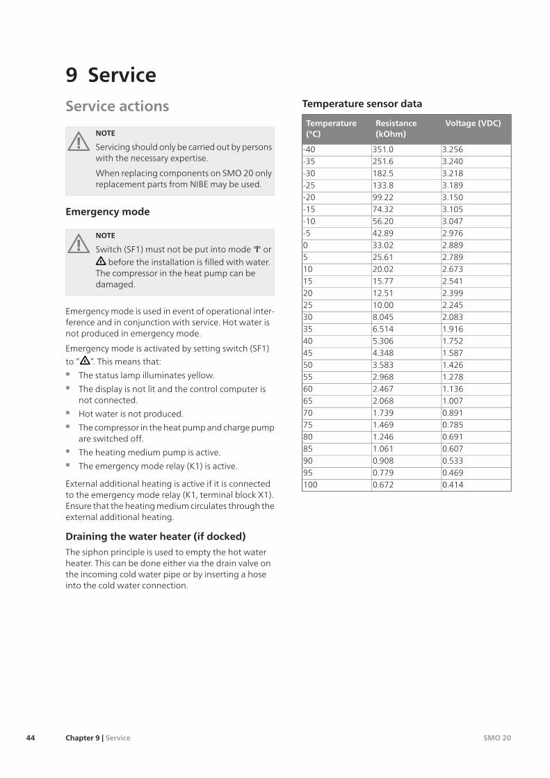
Service actions
NOTE
Servicing should only be carried out by personswith the necessary expertise.
When replacing components on SMO 20 onlyreplacement parts from NIBE may be used.
Emergency mode
NOTE
Switch (SF1) must not be put into mode "" orbefore the installation is filled with water.
The compressor in the heat pump can bedamaged.
Emergency mode is used in event of operational inter-ference and in conjunction with service. Hot water isnot produced in emergency mode.
Emergency mode is activated by setting switch (SF1)
to ” ”. This means that:
The status lamp illuminates yellow.
The display is not lit and the control computer isnot connected.
Hot water is not produced.
The compressor in the heat pump and charge pumpare switched off.
The heating medium pump is active.
The emergency mode relay (K1) is active.
External additional heating is active if it is connectedto the emergency mode relay (K1, terminal block X1).Ensure that the heating medium circulates through theexternal additional heating.
Draining the water heater (if docked)
The siphon principle is used to empty the hot waterheater. This can be done either via the drain valve onthe incoming cold water pipe or by inserting a hoseinto the cold water connection.
Temperature sensor data
Voltage (VDC)Resistance(kOhm)
Temperature(°C)
3.256351.0-403.240251.6-353.218182.5-303.189133.8-253.15099.22-203.10574.32-153.04756.20-102.97642.89-52.88933.0202.78925.6152.67320.02102.54115.77152.39912.51202.24510.00252.0838.045301.9166.514351.7525.306401.5874.348451.4263.583501.2782.968551.1362.467601.0072.068650.8911.739700.7851.469750.6911.246800.6071.061850.5330.908900.4690.779950.4140.672100
SMO 20Chapter 9 | Service44
9 Service
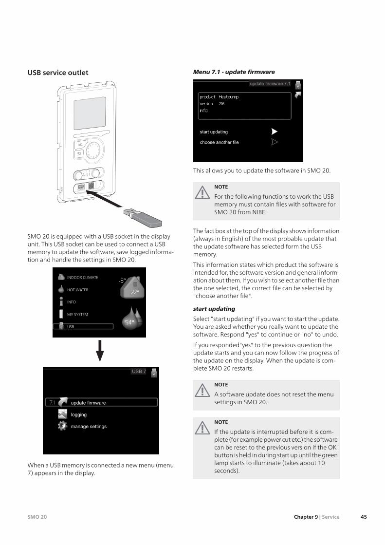
USB service outlet
LE
K
SMO 20 is equipped with a USB socket in the displayunit. This USB socket can be used to connect a USBmemory to update the software, save logged informa-tion and handle the settings in SMO 20.
USB
INDOOR CLIMATE
MY SYSTEM
INFO
HOT WATER
When a USB memory is connected a new menu (menu7) appears in the display.
Menu 7.1 - update firmware
This allows you to update the software in SMO 20.
NOTE
For the following functions to work the USBmemory must contain files with software forSMO 20 from NIBE.
The fact box at the top of the display shows information(always in English) of the most probable update thatthe update software has selected form the USBmemory.
This information states which product the software isintended for, the software version and general inform-ation about them. If you wish to select another file thanthe one selected, the correct file can be selected by"choose another file".
start updating
Select “start updating" if you want to start the update.You are asked whether you really want to update thesoftware. Respond "yes" to continue or "no" to undo.
If you responded"yes" to the previous question theupdate starts and you can now follow the progress ofthe update on the display. When the update is com-plete SMO 20 restarts.
NOTE
A software update does not reset the menusettings in SMO 20.
NOTE
If the update is interrupted before it is com-plete (for example power cut etc.) the softwarecan be reset to the previous version if the OKbutton is held in during start up until the greenlamp starts to illuminate (takes about 10seconds).
45Chapter 9 | ServiceSMO 20
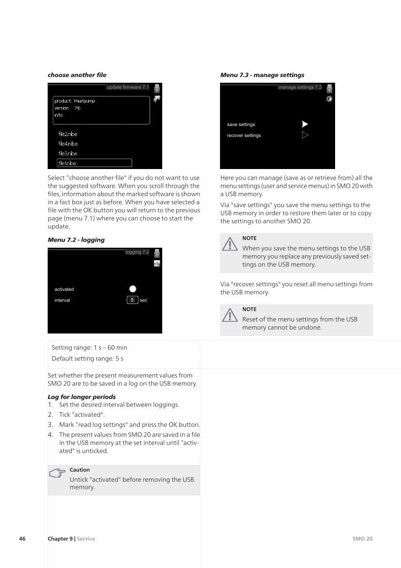
choose another file
Select “choose another file" if you do not want to usethe suggested software. When you scroll through thefiles, information about the marked software is shownin a fact box just as before. When you have selected afile with the OK button you will return to the previouspage (menu 7.1) where you can choose to start theupdate.
Menu 7.2 - logging
Setting range: 1 s – 60 min
Default setting range: 5 s
Set whether the present measurement values fromSMO 20 are to be saved in a log on the USB memory.
Log for longer periods1. Set the desired interval between loggings.
2. Tick “activated".
3. Mark “read log settings" and press the OK button.
4. The present values from SMO 20 are saved in a filein the USB memory at the set interval until “activ-ated" is unticked.
Caution
Untick "activated" before removing the USBmemory.
Menu 7.3 - manage settings
Here you can manage (save as or retrieve from) all themenu settings (user and service menus) in SMO 20 witha USB memory.
Via "save settings" you save the menu settings to theUSB memory in order to restore them later or to copythe settings to another SMO 20.
NOTE
When you save the menu settings to the USBmemory you replace any previously saved set-tings on the USB memory.
Via "recover settings" you reset all menu settings fromthe USB memory.
NOTE
Reset of the menu settings from the USBmemory cannot be undone.
SMO 20Chapter 9 | Service46
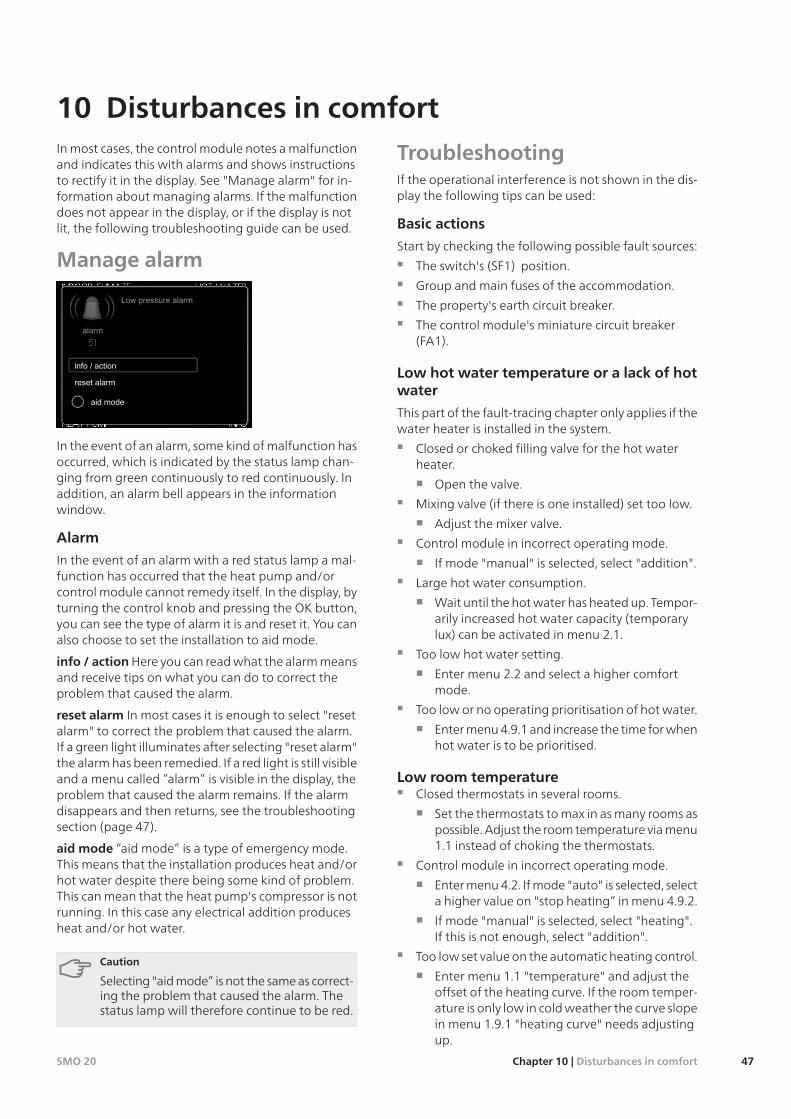
In most cases, the control module notes a malfunctionand indicates this with alarms and shows instructionsto rectify it in the display. See "Manage alarm" for in-formation about managing alarms. If the malfunctiondoes not appear in the display, or if the display is notlit, the following troubleshooting guide can be used.
Manage alarm
In the event of an alarm, some kind of malfunction hasoccurred, which is indicated by the status lamp chan-ging from green continuously to red continuously. Inaddition, an alarm bell appears in the informationwindow.
Alarm
In the event of an alarm with a red status lamp a mal-function has occurred that the heat pump and/orcontrol module cannot remedy itself. In the display, byturning the control knob and pressing the OK button,you can see the type of alarm it is and reset it. You canalso choose to set the installation to aid mode.
info / action Here you can read what the alarm meansand receive tips on what you can do to correct theproblem that caused the alarm.
reset alarm In most cases it is enough to select "resetalarm" to correct the problem that caused the alarm.If a green light illuminates after selecting "reset alarm"the alarm has been remedied. If a red light is still visibleand a menu called ”alarm” is visible in the display, theproblem that caused the alarm remains. If the alarmdisappears and then returns, see the troubleshootingsection (page 47).
aid mode ”aid mode” is a type of emergency mode.This means that the installation produces heat and/orhot water despite there being some kind of problem.This can mean that the heat pump's compressor is notrunning. In this case any electrical addition producesheat and/or hot water.
Caution
Selecting "aid mode” is not the same as correct-ing the problem that caused the alarm. Thestatus lamp will therefore continue to be red.
TroubleshootingIf the operational interference is not shown in the dis-play the following tips can be used:
Basic actions
Start by checking the following possible fault sources:
The switch's (SF1) position.
Group and main fuses of the accommodation.
The property's earth circuit breaker.
The control module's miniature circuit breaker(FA1).
Low hot water temperature or a lack of hotwater
This part of the fault-tracing chapter only applies if thewater heater is installed in the system.
Closed or choked filling valve for the hot waterheater.
Open the valve.
Mixing valve (if there is one installed) set too low.
Adjust the mixer valve.
Control module in incorrect operating mode.
If mode "manual" is selected, select "addition".
Large hot water consumption.
Wait until the hot water has heated up. Tempor-arily increased hot water capacity (temporarylux) can be activated in menu 2.1.
Too low hot water setting.
Enter menu 2.2 and select a higher comfortmode.
Too low or no operating prioritisation of hot water.
Enter menu 4.9.1 and increase the time for whenhot water is to be prioritised.
Low room temperatureClosed thermostats in several rooms.
Set the thermostats to max in as many rooms aspossible. Adjust the room temperature via menu1.1 instead of choking the thermostats.
Control module in incorrect operating mode.
Enter menu 4.2. If mode "auto" is selected, selecta higher value on "stop heating“ in menu 4.9.2.
If mode "manual" is selected, select "heating".If this is not enough, select "addition".
Too low set value on the automatic heating control.
Enter menu 1.1 "temperature" and adjust theoffset of the heating curve. If the room temper-ature is only low in cold weather the curve slopein menu 1.9.1 "heating curve" needs adjustingup.
47Chapter 10 | Disturbances in comfortSMO 20
10 Disturbances in comfort
Too low or no operating prioritisation of heat.
Enter menu 4.9.1 and increase the time for whenheating is to be prioritised.
"Holiday mode" activated in menu 4.7.
Enter menu 4.7 and select “Off”.
External switch for changing the room heating ac-tivated.
Check any external switches.
Air in the climate system.
Vent the climate system.
Closed valves (QM20), (QM32)to the climate system.
Open the valves.
High room temperatureToo high set value on the automatic heating control.
Enter menu 1.1 (temperature) and adjust theheat curve offset downwards. If the room tem-perature is only high in cold weather the curveslope in menu 1.9.1 (heating curve) needs to beadjusted down.
External switch for changing the room heating ac-tivated.
Check any external switches.
Low system pressureNot enough water in the climate system.
Top up the water in the climate system.
The compressor does not startThere is no heating requirement.
The heat pump does not call on heating nor hotwater.
Temperature conditions tripped.
Wait until the temperature condition has beenreset.
Minimum time between compressor starts has notbeen reached.
Wait 30 minutes and check if the compressorhas started.
Alarm tripped.
Follow the display instructions.
Additional heating onlyIf you are unsuccessful in rectifying the fault and areunable to heat the house, you can, whilst waiting forassistance, continue running the heat pump in ”add.heat only”. This means that additional heating only isused to heat the house.
Set the installation to additional heat mode1. Go to menu 4.2 op. mode.
2. Mark ”add. heat only” using the control knob andthen press the OK button.
3. Return to the main menus by pressing the Backbutton.
NOTE
If a heat pump is not connected by pipes tothe system the flow must be shut off (the pipeends connected to each other) where the heatpump should have been installed.
Caution
When commissioning without NIBE air/waterheat pump an alarm communication error mayappear in the display.
The alarm is reset if the relevant heat pump isdeactivated in menu 5.2.2 ("installed slaves").
SMO 20Chapter 10 | Disturbances in comfort48
Auxiliary relay HR 10
Part no. 067 309
Charge pump CPD 10
Charge pump for heat pump
CPD 10-25/55, Part no. 067 305
CPD 10-25/60, Part no. 067 306
Connection box K11
Connection box with thermostat and overheatingprotection.
Part no. 018 893
External electrical addition ELK
ELK 5
Immersion heater
5 kW, 1 x 230 V
Part no. 069 025
ELK 8
Immersion heater
8 kW, 1 x 230 V
Part no. 069 026
ELK 15
Immersion heater
15 kW, 3 x 400 V
Part no. 069 022
ELK 26
Immersion heater
26 kW, 3 x 400 V
Part no. 067 074
Heat pump
F2026
6 kW Part no. 064 084
8 kW Part no. 064 085
10 kW Part no. 064 086
F2030
7 kW Part no. 064 099
9 kW Part no. 064 070
F2040
8 kW Part no. 064 109
12 kW Part no. 064 092
16 kW Part no. 064 108
F2300
14 kW Part no. 064 063
20 kW Part no. 064 064
Hot water control
VST 05
Three way valve, Cu-pipe Ø22
Max heat pump size 8 kW
Part no. 089 882
VST 11
Shuttle valve, Cu-pipe Ø28(Max recommended power, 17 kW)
Part no. 089 152
VST 20
Reversing valve, Cu-pipe Ø35(Max recommended power, 40 kW)
Part no. 089 388
Immersion heater IU
3 kW Part no. 018 084
6 kW Part no. 018 088
9 kW Part no. 018 090
Room sensor RTS 40
Part no. 067 065
Water heater/Accumulator tank
VPA 450/300
Copper Part no. 088 660
Enamel Part no. 088 670
VPB 200
Copper Part no. 088 515
Enamel Part no. 088 517
Stainless steel Part no 088 518
VPB 300
Copper Part no. 083 009
Enamel Part no. 083 011
Stainless steel Part no 083 010
VPB 500
Hot water heater with charge coil
Copper Part no. 083 220
VPB 750-2
Hot water heater with charge coil
Copper Part no. 083 231
49Chapter 11 | AccessoriesSMO 20
11 Accessories

VPB 1000
Hot water heater with charge coil
Copper Part no. 083 240
VPAS 300/450
Copper Part no. 087 720
Enamel Part no. 087 710
SMO 20Chapter 11 | Accessories50
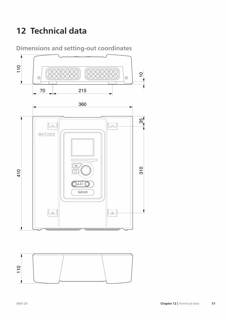
Dimensions and setting-out coordinates
110
410
360
110
10310
21570
35
51Chapter 12 | Technical dataSMO 20
12 Technical data
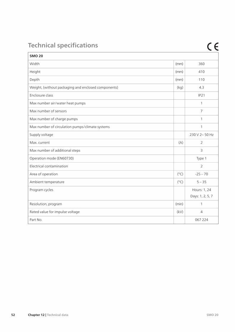
Technical specifications
SMO 20
360(mm)Width
410(mm)Height
110(mm)Depth
4.3(kg)Weight, (without packaging and enclosed components)
IP21Enclosure class
1Max number air/water heat pumps
7Max number of sensors
1Max number of charge pumps
1Max number of circulation pumps/climate systems
230 V 2~ 50 HzSupply voltage
2(A)Max. current
3Max number of additional steps
Type 1Operation mode (EN60730)
2Electrical contamination
-25 – 70(°C)Area of operation
5 – 35(°C)Ambient temperature
Hours: 1, 24Program cycles
Days: 1, 2, 5, 7
1(min)Resolution, program
4(kV)Rated value for impulse voltage
067 224Part No.
SMO 20Chapter 12 | Technical data52
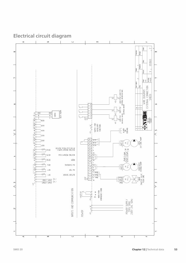
Electrical circuit diagram
53Chapter 12 | Technical dataSMO 20
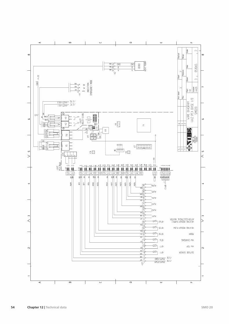
SMO 20Chapter 12 | Technical data54
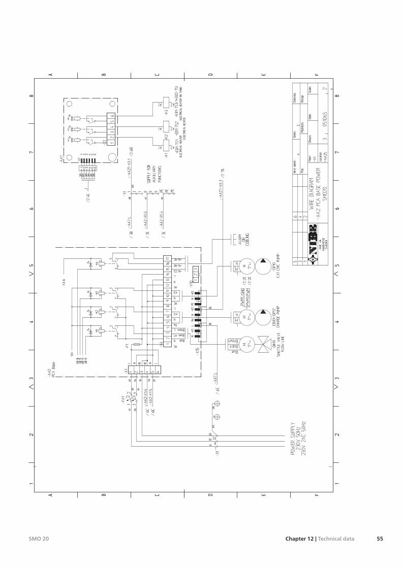
55Chapter 12 | Technical dataSMO 20

SMO 20Chapter 12 | Technical data56
Item register
AAccessibility, electrical connection, 12Accessories, 49
BBack button, 23
CCable lock, 13Commissioning and adjusting, 21
Commissioning with additional heating only, 21Commissioning with NIBE air/water heat pump, 21Preparations, 21Start guide, 22
Commissioning with additional heating only, 21Commissioning with NIBE air/water heat pump, 21Communication with heat pump, 14Connecting accessories, 20Connecting the charge pump for the heat pump, 14Connections, 14Contact for activation of “external adjustment", 19Contact for activation of “temporary lux", 19Contact for external blocking of compressor in the heat pump, 19Contact for external tariff blocking, 19Contact information, 4Control, 23, 27
Control - Introduction, 23Control - Menus, 27
Control - Introduction, 23Display unit, 23Menu system, 24
Control knob, 23Control - Menus, 27
Menu 1 - INDOOR CLIMATE, 27Menu 2 - HOT WATER, 32Menu 3 - INFO, 34Menu 4 - MY SYSTEM, 35Menu 5 - SERVICE, 39
DDelivery and handling, 5
Mounting, 5Supplied components, 5
Display, 23Display unit, 23
Back button, 23Control knob, 23Display, 23OK button, 23Status lamp, 23Switch, 23
Disturbances in comfort, 47Manage alarm, 47Only additional heat, 48Troubleshooting, 47
Docking alternatives, 8Draining the hot water heater, 44
EElectrical connections, 11
Accessibility, electrical connection, 12Cable lock, 13Communication with heat pump, 14Connecting accessories, 20Connecting the charge pump for the heat pump, 14Connections, 14External circulation pump, 18External connection options, 18General, 11
Miniature circuit-breaker, 11Optional connections, 16Outdoor sensor, 15Power connection, 14Relay output for emergency mode, 17Reversing valve, 18Room sensor, 16St controlled additional heat, 17Temperature sensor, external flow line, 15Temperature sensor, external supply line after electric heat-er, 16Temperature sensor, hot water charging, 15
External circulation pump, 18External connection options, 18
Contact for activation of “external adjustment", 19Contact for activation of “temporary lux", 19Contact for external blocking of compressor in the heatpump, 19Contact for external tariff blocking, 19Extra circulation pump, 20Hot water circulation, 20Possible selection for AUX inputs, 18Possible selection for AUX output (potential free variable re-lay), 20Switch for "Smart Grid ready", 19Switch for external blocking of additional heat, 19Switch for external blocking of heating, 19Temperature sensor, external flow line, 19Temperature sensor, hot water top, 15
Extra circulation pump, 20
HHelp menu, 22, 26Hot water circulation, 20
IImportant information, 2
Safety information, 2Inspection of the installation, 3
MManage alarm, 47Marking, 2Menu 1 - INDOOR CLIMATE, 27Menu 2 - HOT WATER, 32Menu 3 - INFO, 34Menu 4 - MY SYSTEM, 35Menu 5 - SERVICE, 39Menu system, 24
Help menu, 22, 26Operation, 25Scroll through the windows, 26Selecting menu, 25Selecting options, 25Setting a value, 25
Miniature circuit-breaker, 11Mounting, 5
OOK button, 23Only additional heat, 48Operation, 25Optional connections, 16Outdoor sensor, 15
PPipe connections, 7
Docking alternatives, 8General, 7Symbol key, 7
57Chapter 13 | Item registerSMO 20
13 Item register
Possible selection for AUX inputs, 18Possible selection for AUX output (potential free variable relay), 20Power connection, 14Preparations, 21
RRelay output for emergency mode, 17Reversing valve, 18Room sensor, 16
SSafety information, 2
Contact information, 4Inspection of the installation, 3Marking, 2Serial number, 2Symbols, 2
Scroll through the windows, 26Selecting menu, 25Selecting options, 25Serial number, 2Service, 44
Service actions, 44Service actions, 44
Draining the hot water heater, 44Standby mode, 44Temperature sensor data, 44USB service outlet, 45
Setting a value, 25Standby mode, 44Start guide, 22Status lamp, 23
Supplied components, 5Switch, 23Switch for "Smart Grid ready", 19Switch for external blocking of additional heat, 19Switch for external blocking of heating, 19Symbol key, 7Symbols, 2
TTechnical data, 51
Technical Data, 52Technical Data, 52Temperature sensor, external flow line, 15, 19Temperature sensor, external supply line after electric heater, 16Temperature sensor, hot water charging, 15Temperature sensor, hot water top, 15Temperature sensor data, 44The Control Module Design, 6
Component locations, 6List of components, 6
Troubleshooting, 47
UUSB service outlet, 45
SMO 20Chapter 13 | Item register58

59Chapter 13 |SMO 20

SMO 20Chapter 13 |60

