installation, start-up, and operating instructions deluxe
TRANSCRIPT

NOTE: Read the entire instruction manual before starting theinstallation.
This symbol→ indicates a change since the last issue.
Index Page
DIMENSIONAL DRAWING........................................................2SAFETY CONSIDERATIONS .....................................................3
Clearances to Combustibles......................................................3ELECTROSTATIC DISCHARGE (ESD) PRECAUTIONS ....3-4INTRODUCTION..........................................................................4APPLICATIONS ......................................................................4-11
General ......................................................................................4Upflow Applications..............................................................4-7Downflow Applications.........................................................7-8Horizontal Left (Supply-Air Discharge) Applications .........8-9Horizontal Right (Supply-Air Discharge) Applications.....9-11
LOCATION ............................................................................11-12General...............................................................................11-12Furnace Location Relative to Cooling Equipment ................12Hazardous Locations...............................................................12
INSTALLATION....................................................................13-17Leveling Legs (If Desired) .....................................................13Installation In Upflow and Downflow Applications ........13-15Installation In Horizontal Applications ..................................15Filter Arrangement..................................................................16Bottom Closure Panel.............................................................16Gas Piping...............................................................................17
ELECTRICAL CONNECTIONS...........................................17-21115-v Wiring......................................................................17-1824-v Wiring.............................................................................18Wiring Diagram ......................................................................19Accessories ........................................................................20-21
DIRECT VENTING ...............................................................21-29Removal of Existing Furnaces from
Common Vent Systems.....................................................21Combustion-Air and Vent Piping .....................................21-27Concentric Vent and Combustion-Air Termination
Kit Installation..............................................................27-29Multiventing and Vent Termination.......................................29
CONDENSATE DRAIN ........................................................29-31General ....................................................................................29Application..............................................................................29Condensate Drain Protection.............................................29-31
SEQUENCE OF OPERATION..............................................31-33Heating Mode ....................................................................31-32Cooling Mode .........................................................................32Continuous Blower Mode.......................................................32Heat Pump Mode....................................................................32Component Test.................................................................32-33
START-UP PROCEDURES ..................................................33-41General ....................................................................................33Prime Condensate Trap With Water ......................................33Purge Gas Lines......................................................................34Adjustments .......................................................................34-41Set Gas Input Rate ............................................................34-40Set Temperature Rise ........................................................40-41Adjust Blower Off Delay (Heat Mode) .................................41Set Thermostat Heat Anticipator............................................41
CHECK SAFETY CONTROLS..................................................41Check Primary Limit Control.................................................41Check Pressure Switch ...........................................................41
CHECKLIST...........................................................................41-42
A93040
® ama CANADIAN GAS ASSOCIATION
A PP R O VEDR
As an ENERGY STARSM
Partner, Bryant/Day &Night has determined thatthis product meets the EN-ERGY STAR guidelinesfor energy efficiency.
CERTIFICATION OF MANUFACTURING SITE
Fig. 1—Multipoise OrientationsA93041
UPFLOW
DOWNFLOW
HORIZONTAL LEFT
AIRFLOW AIRFLOW
AIRFLOW
AIRFLOW
HORIZONTAL RIGHT
installation, start-up,and operating instructionsDELUXE 4-WAY MULTIPOISEFIXED-CAPACITY DIRECT-VENTCONDENSING GAS FURNACE
Cancels: II 350M-40-7 II 350M-40-812-96
350MAV
Series D
—1—
Downloaded from www.Manualslib.com manuals search engine

Fig.2—
DimensionalDrawing
DIMENSIONS(IN.)
UNIT
SIZE
AD
E024040
17-1/2
15-7/8
16036040
17-1/2
15-7/8
16024060
17-1/2
15-7/8
16036060
17-1/2
15-7/8
16048060
17-1/2
15-7/8
16036080
17-1/2
15-7/8
16048080
17-1/2
15-7/8
16060080
2119-3/8
19-1/2
048100
2119-3/8
19-1/2
060100
2119-3/8
19-1/2
060120
24-1/2
22-7/8
23060140
24-1/2
22-7/8
23
A93023
17 5 ⁄1
6"24 1 ⁄2
"27 9 ⁄1
6"
TY
P
27 5 ⁄8
"29 11
⁄16"
TY
P
30 13
⁄16"32
5 ⁄8"
TY
P
33 1 ⁄4
" T
YP
CO
ND
EN
SA
TE
D
RA
IN T
RA
P
LOC
AT
ION
(A
LTE
RN
AT
E
UP
FLO
W)
7 ⁄8-I
N. D
IA
AC
CE
SS
OR
Y
PO
WE
R E
NT
RY
7 ⁄8-I
N. D
IA
PO
WE
R C
ON
N
CO
ND
EN
SA
TE
DR
AIN
T
RA
P L
OC
AT
ION
(D
OW
NF
LOW
&
HO
RIZ
ON
TA
L LE
FT
)
26 15
⁄16"
24 1 ⁄2
"
22 5 ⁄1
6"
2-IN
. CO
MB
US
TIO
N-
AIR
CO
NN
1 ⁄2-I
N. D
IA
GA
S C
ON
N
2-IN
. VE
NT
CO
NN
1 ⁄2-I
N. D
IA T
HE
RM
OS
TA
T
EN
TR
Y22
11⁄16
"
SID
E IN
LET
23 1 ⁄4
" T
YP
S
IDE
INLE
T
11 ⁄4"
1"
OU
TLE
T
26 15
⁄16"
28 1 ⁄2
"
22 5 ⁄1
6"
19"
13⁄16
"5 ⁄8
" 5 ⁄16"
1"
39 7 ⁄8
"
22 1 ⁄4
" T
YP
11⁄16
"
7 ⁄16"
24 3 ⁄1
6"B
OT
TO
M IN
LET
18 1 ⁄4
"
22 11
⁄16"
2-IN
. CO
MB
US
TIO
N-
AIR
CO
NN 1 ⁄2
-IN
. DIA
G
AS
CO
NN
7 ⁄8-I
N. D
IA
PO
WE
R C
ON
N
1 ⁄2-I
N. D
IA
TH
ER
MO
ST
AT
EN
TR
Y
2-IN
. VE
NT
CO
NN
DIM
PLE
LO
CA
TO
RS
F
OR
HO
RIZ
ON
TA
L H
AN
GIN
G
14 1 ⁄2
" T
YP
SID
E IN
LET
NO
TES
: M
inim
um r
etur
n-ai
r op
enin
g at
furn
ace:
1.
2.
3.
4.
For
800
CF
M--
16-I
n. r
ound
or
14 1
/2 x
12-
In. r
ecta
ngle
. F
or 1
200
CF
M--
20-I
n. r
ound
or
14 1
/2 x
19
1 /2-
In. r
ecta
ngle
. F
or 1
600
CF
M--
22-I
n. r
ound
or
14 1
/2 x
23
1 /4-
In. r
ecta
ngle
. F
or a
irflo
w r
equi
rem
ents
abo
ve 1
800
CF
M, u
se b
oth
side
inle
ts, a
co
mbi
natio
n of
1 s
ide
inle
t and
the
botto
m, o
r th
e bo
ttom
onl
y.
9 7 ⁄1
6"
TY
P
26 15
⁄16"
TY
P
CO
ND
EN
SA
TE
D
RA
IN L
OC
AT
ION
(U
PF
LOW
)
30 1 ⁄2
"
9 ⁄16"
T
YP
CO
ND
EN
SA
TE
D
RA
IN L
OC
AT
ION
(U
PF
LOW
)E
INLE
T
11/16
"11
/16"
D13
/16"
13/16
"
OU
TLE
T
A
AIR
FLO
W26
1 ⁄4"
26 1 ⁄4
"
CO
ND
EN
SA
TE
DR
AIN
T
RA
P L
OC
AT
ION
(D
OW
NF
LOW
&
HO
RIZ
ON
TA
L R
IGH
T)
OR
ALT
ER
NA
TE
1 ⁄2
-IN
. DIA
GA
S C
ON
N
—2—
Downloaded from www.Manualslib.com manuals search engine

SAFETY CONSIDERATIONSInstalling and servicing heating equipment can be hazardous due togas and electrical components. Only trained and qualified person-nel should install, repair, or service heating equipment. Untrainedpersonnel can perform basic maintenance functions such as clean-ing and replacing air filters. All other operations must be per-formed by trained service personnel. When working on heatingequipment, observe precautions in literature, on tags, and on labelsattached to or shipped with unit and other safety precautions thatmay apply.Follow all safety codes. In the United States, follow all safetycodes including the National Fuel Gas Code (NFGC) NFPA No.54-1996/ANSI Z223.1-1996 and the Installation Standards, WarmAir Heating and Air Conditioning Systems (NFPA 90B)ANSI/NFPA 90B. In Canada, refer to the current edition of theNational Standard of Canada CAN/CGA-B149.1- and .2-M95Natural Gas and Propane Installation Codes (NSCNGPIC). Wearsafety glasses and work gloves. Have fire extinguisher availableduring start-up and adjustment procedures and service calls.Recognize safety information. This is the safety-alert symbol.When you see this symbol on unit or in instructions and manuals,be alert to potential for personal injury.Understand the signal words DANGER, WARNING, and CAU-TION. These words are used with the safety-alert symbol. DAN-GER identifies most serious hazards whichwill result in severepersonal injury or death. WARNING signifies hazards whichcould result in personal injury or death. CAUTION is used toidentify unsafe practices whichwould result in minor personalinjury or product and property damage. NOTE is used to highlightsuggestions whichwill result in enhanced installation, reliability,or operation.
ELECTROSTATIC DISCHARGE (ESD) PRECAUTIONS
CAUTION: Electrostatic discharge can affect electroniccomponents. Take precautions during furnace installationand servicing to protect the furnace electronic control.Precautions will prevent electrostatic discharges frompersonnel and hand tools which are held during theprocedure. These precautions will help to avoid exposingthe control to electrostatic discharge by putting thefurnace, the control, and the person at the same electro-static potential.
1. Disconnect all power to the furnace. DO NOT TOUCHTHE CONTROL ORANY WIRE CONNECTED TO THECONTROL PRIOR TO DISCHARGING YOUR BODY’SELECTROSTATIC CHARGE TO GROUND.
2. Firmly touch a clean, unpainted, metal surface of thefurnace chassis which is close to the control. Tools held ina person’s hand during grounding will be satisfactorilydischarged.
3. After touching the chassis you may proceed to service thecontrol or connecting wires as long as you do nothing thatrecharges your body with static electricity (for example; DONOT move or shuffle your feet, DO NOT touch un-grounded objects, etc.).
4. If you touch ungrounded objects (recharge your body withstatic electricity), firmly touch furnace again before touch-ing control or wires.
5. Use this procedure for installed and uninstalled (un-grounded) furnaces.
→ Fig. 3—Clearances to CombustiblesA96313
323855-101 REV. A (LIT)
*1 1 0 3 01 0 0 3 0
This forced air furnace is equipped for use with natural gas at altitudes 0 - 10,000 ft (0 - 3,050m),except 140 size Furnaces are only approved for altitudes 0 - 7,000 ft. (0 - 2,135m).
An accessory kit, supplied by the manufacturer, shall be used to convert to propane gas use or may berequired for some natural gas applications.
This direct-vent, forced-air furnace is for indoor installation in a building constructed on site or in amanufactured (mobile) home when using factory authorized kit, see rating plate.
This furnace may be installed on combustible flooring in alcove or closet at minimum clearance fromcombustible material.
This appliance requires a special venting system. Refer to the installation instructions for parts list andmethod of installation. This furnace is for use with schedule-40 PVC, PVC-DWV, or ABS-DWV pipe, andmust not be vented in common with other gas-fired appliances. Construction through which vent/air intakepipes may be installed is maximum 24 inches (600 mm), minimum 3/4 inches (19 mm) thickness (includingroofing materials).
VENTFRONTBACKSIDESTOP / PLENUM
03001
BOTTOM
0†
0
*
For Installation on combustible floors only when installed on special base No. KGASB0201ALL,Coil Assembly, Part No. CD5 or CK5, or Coil Casing, Part No. KCAKC.
Clearance shown is for air inlet and air outlet end.Horizontal position: Line contact is permissible only between lines formed by intersections
of top and two sides of furnace jacket, and building joists, studs, or framing.
120 and 140 size Furnaces require 1 inch bottom clearance to combustible materials.
Minimum front clearance for service 30 inches (762mm).
140 size Furnaces require 1 inch back clearance to combustible materials.
Ø
UPFLOW
DOWNFLOW
HORIZONTAL
INSTALLATION
Ø
MINIMUM INCHES CLEARANCE TO COMBUSTIBLE CONSTRUCTION
§**
†
§
††
††††††
—3—
→
Downloaded from www.Manualslib.com manuals search engine

6. Before removing a new control from its container, dis-charge your body’s electrostatic charge to ground to protectthe control from damage. If the control is to be installed ina furnace, follow items 1 through 5 before bringing thecontrol or yourself into contact with the furnace. Put allused AND new controls into containers before touchingungrounded objects.
7. An ESD service kit (available from commercial sources)may also be used to prevent ESD damage.
INTRODUCTIONThe model 350MAV, Series D Furnaces are available in sizes40,000 through 138,000 Btuh input capacities.The 350MAV Multipoise Condensing Gas-Fired Furnaces areA.G.A./C.G.A. certified for natural and propane gases and forinstallation in alcoves, attics, basements, closets, utility rooms,crawlspaces, and garages. The furnace is factory-shipped for usewith natural gas. An A.G.A./C.G.A. listed gas conversion kit isrequired to convert furnace for use with propane gas. The350MAV 040 through 120 size units are A.G.A./C.G.A. approvedfor use in manufactured (mobile) homes when factory accessoryconversion kit is used. The 140 size unit is NOT approved for usein manufactured (mobile) homes. These furnaces are suitable forinstallation in a residence built on site or a manufactured residencecompleted at final site. The design of this furnace line is NOTA.G.A./C.G.A. certified for installation in recreation vehicles oroutdoors.These furnaces SHALL NOT be installed directly on carpeting,tile, or any other combustible material other than wood flooring. Indownflow installations, factory accessory floor base MUST beused when installed on combustible materials and wood flooring.Special base is not required when this furnace is installed onmanufacturer’s Coil Assembly Part No. CD5 or CK5, or when CoilBox Part No. KCAKC is used.These furnaces are shipped with the drain and pressure tubesconnected for UPFLOW applications. Minor modifications arerequired when used in DOWNFLOW, HORIZONTAL RIGHT, orHORIZONTAL LEFT (supply-air discharge direction) applica-tions as shown in Fig. 1. See details in Applications section.These furnaces are shipped with the following materials to assist inproper furnace installation. These materials are shipped in the mainblower compartment.
Installer Packet includes:Installation, Start-Up, and Operating InstructionsService and Maintenance InstructionsUser’s Information ManualWarranty Certificate
Loose Parts Bag includes: QuantityPressure tube extension 1Collector box or condensate trap extension tube 1Inducer housing drain tube 11/2-in. CPVC street elbow 2Drain tube coupling 1Drain tube coupling grommet 1Vent and combustion-air pipe support 2Combustion-air pipe perforated disk assembly 1
Vent Pipe Extension 1** ONLY supplied with some furnaces.Before installing the furnace in the United States, refer to thecurrent edition of the NFGC and the NFPA 90B. For furtherinformation, the NFGC and the NFPA 90B are available fromNational Fire Protection Association Inc., Batterymarch Park,Quincy, MA 02269; American Gas Association, 1515 WilsonBoulevard, Arlington, VA 22209; or from Literature Distribution.Before installing the furnace in Canada, refer to the current editionof the NSCNGPIC. Contact Standards Department of CanadianGas Association, 55 Scarsdale Road, Don Mills, Ontario, CanadaM3B 2R3.
Installations must comply with regulations of serving gas supplierand local building, heating, plumbing, or other codes in effect inarea in which installation is made. In absence of local codes,installation must conform with NFGC.
Canadian installations must be made in accordance with NSCNG-PIC and all authorities having jurisdiction.
These instructions cover minimum requirements for a safe instal-lation and conform to existing national standards and safety codes.In some instances, these instructions exceed certain local codesand ordinances, especially those that may not have kept pace withchanging residential construction practices. We require theseinstructions as a minimum for a safe installation.
CAUTION: Application of this furnace should be in-doors with special attention given to vent sizing andmaterial, gas input rate, air temperature rise, unit leveling,and unit sizing. Improper installation or misapplication offurnace can require excessive servicing or cause prema-ture component failure.
WARNING: Improper installation, adjustment, alter-ation, service, maintenance, or use can cause carbonmonoxide poisoning, explosion, fire, electrical shock, orother conditions which may cause personal injury orproperty damage. Consult a qualified installer, serviceagency, local gas supplier, or your distributor or branchfor information or assistance. The qualified installer oragency must use only factory-authorized and listed kits oraccessories when modifying this product. Failure tofollow this warning could result in electrical shock, fire,personal injury, or death.
For accessory installation details, refer to applicable installationliterature.
APPLICATIONS
I. GENERAL
Some assembly and modifications are required for furnacesinstalled in any of the 4 applications shown in Fig. 1. All drain andpressure tubes are connected as shown in Fig. 5. See appropriateapplication instructions for these procedures.
II. UPFLOW APPLICATIONS
An upflow furnace application is where furnace blower is locatedbelow combustion and controls section of furnace, and conditionedair is discharged upwards.
A. Condensate Trap Location (Factory-ShippedOrientation)
The condensate trap is factory installed in the blower shelf andfactory connected for UPFLOW applications. A factory-suppliedtube is used to extend the condensate trap drain connection to thedesired furnace side for field drain attachment. See CondensateTrap Tubing (Factory-Shipped Orientation) section for drain tubeextension details.
B. Condensate Trap Tubing (Factory-Shipped Orienta-tion)
NOTE: See Fig. 5 or tube routing label on main furnace door toconfirm location of these tubes.
1. Collector Box Drain, Inducer Housing Drain, Relief Port,and Pressure Switch Tubes
These tubes should be factory attached to condensate trapand pressure switch ready for use in UPFLOW applications.These tubes can be identified by their connection location
—4—
→
→
→
Downloaded from www.Manualslib.com manuals search engine

and also by a color label on each tube. These tubes areidentified as follows: collector box drain tube (blue label),inducer housing drain tube (violet label or molded), reliefport tube (green label), and pressure switch tube (pinklabel).
2. Condensate Trap Drain Tube
The condensate trap drain connection must be extended forfield attachment by doing the following:a. Determine location of field drain connection. (See Fig. 2
or 5.)
NOTE: If internal filter is used, drain tube should be located toopposite side of casing of return duct attachment to assist in filterremoval.
b. Remove and discard casing drain hole plug button fromdesired side.
c. Install drain tube coupling grommet (factory-supplied inloose parts bag) in selected casing hole.
d. Slide drain tube coupling (factory-supplied in loose partsbag) through grommet ensuring long end of couplingfaces blower.
e. Cement 2 factory-supplied 1/2-in. street CPVC elbows tothe rigid drain tube connection on the condensate trap.(See Fig. 5.) These elbows must be cemented togetherand cemented to condensate trap drain connection.
NOTE: Failure to use CPVC elbows may allow drain to kink andprevent draining.
f. Connect larger diameter drain tube and clamp (factory-supplied in loose parts bag) to condensate trap and clampsecurely.
g. Route tube to coupling and cut to appropriate length.
h. Attach tube to coupling and clamp securely.
C. Condensate Trap Location (Alternate UpflowOrientation)
An alternate location for the condensate trap is the left-hand sideof casing. (See Fig. 2 and 6.)
NOTE: If the alternate left-hand side of casing location is used,the factory-connected drain and relief port tubes must be discon-nected and modified for attachment. See Condensate Trap Tubing(Alternate Upflow Orientation) section for tubing attachment.
To relocate condensate trap to the left-hand side, perform thefollowing:
1. Remove 3 tubes connected to condensate trap.
2. Remove trap from blower shelf by gently pushing tabsinward and rotating trap.
3. Remove casing hole filler cap from casing hole. (See Fig. 2or 6.)
4. Install casing hole filler cap into blower shelf hole wheretrap was removed.
5. Install condensate trap into left-hand side casing hole byinserting tube connection stubs through casing hole androtating until tabs snap into locking position.
Fig. 4—Condensate TrapA93026
1⁄2 OD INDUCER HOUSING DRAIN CONNECTION
1⁄4 OD COLLECTOR BOX TO TRAP RELIEF PORT
5⁄8 OD COLLECTOR BOX DRAIN CONNECTION
1⁄2-IN. PVC OR CPVC
SCREW HOLE FOR UPFLOW OR DOWN- FLOW APPLICATIONS (OPTIONAL)
1 42
7 8
1 87
SLOT FOR SCREW HORIZONTAL APPLICATION
(OPTIONAL)
WIRE TIE GUIDES (WHEN USED)
1 21
3 41
3 4
FRONT VIEW SIDE VIEW
FURNACE DOOR
FURNACE DOOR CONDENSATE
TRAP
78
1 426
4
FURNACE SIDEFURNACE
SIDE
1 21
1 426
43 45 3 45
4
SIDE VIEW FRONT VIEW END VIEW FRONT VIEW
3 4
DOWNFLOW AND ALTERNATE EXTERNAL UPFLOW APPLICATIONS
HORIZONTAL APPLICATIONS
FIELD DRAIN CONN
FIELD DRAIN CONN
CONDENSATE TRAP (INSIDE)
BLOWER SHELF
ALTERNATE DRAIN TUBE LOCATION
UPFLOW APPLICATIONS
CONDENSATE TRAP DRAIN TUBE LOCATION
—5—
Downloaded from www.Manualslib.com manuals search engine

D. Condensate Trap Tubing (Alternate UpflowOrientation)
NOTE: See Fig. 6 or tube routing label on main furnace door toconfirm location of these tubes.
1. Collector Box Drain Tube
Connect collector box drain tube (blue label) to condensatetrap.
NOTE: On 17-1/2-in. wide furnaces ONLY, cut tube betweencorrugated sections to prevent kinks from occurring.
2. Inducer Housing Drain Tube
a. Remove and discard LOWER (molded) inducer housingdrain tube which was previously connected to conden-sate trap.
b. Use inducer housing drain extension tube (violet labeland factory-supplied in loose parts bag) to connectLOWER inducer housing drain connection to the con-densate trap.
c. Determine appropriate length, cut, and connect tube.
d. Clamp tube to prevent any condensate leakage.
3. Relief Port Tube
a. Connect relief port tube (green label) to condensate trap.
b. Extend this tube (if required) by splicing to smalldiameter tube (factory-supplied in loose parts bag).
c. Determine appropriate length, cut, and connect tube.
E. Condensate Trap Field Drain Attachment
Refer to Condensate Drain section for recommendations andprocedures.
F. Pressure Switch Tubing
The LOWER collector box pressure tube (pink label) is factoryconnected to the pressure switch and should not require anymodification.
NOTE: See Fig. 5 or 6 or tube routing label on main furnace doorto check for proper connections.
G. Upper Collector Box and Inducer Housing (Unused)Drain Connections
UPPER COLLECTOR BOX DRAIN CONNECTION
Attached to the UPPER collector box drain connection is afactory-installed corrugated, plugged tube (blue and white stripedlabel). This tube is plugged to prevent condensate leakage in thisapplication. Ensure this tube is plugged.
NOTE: See Fig. 5 or 6 or tube routing label on main furnace doorto check for proper connections.
UPPER INDUCER HOUSING DRAIN CONNECTION
Attached to the UPPER (unused) inducer housing drain connectionis a cap and clamp. This cap is used to prevent condensate leakagein this application. Ensure this connection is capped.
NOTE: See Fig. 5 or 6 or tube routing label on main furnace doorto check for proper connections.
Fig. 5—Factory-Shipped Upflow Tube Configuration(Shown With Blower Access Panel Removed)
A96194
COLLECTOR BOX TUBE (PINK)
COLLECTOR BOX TUBE (GREEN)
INDUCER HOUSING (MOLDED) DRAIN
TUBE (BEHIND COLLECTOR BOX
DRAIN TUBE)
COLLECTOR BOX DRAIN TUBE (BLUE)
FIELD-INSTALLED FACTORY-SUPPLIED
DRAIN TUBE COUPLING (LEFT
DRAIN OPTION)
FIELD-INSTALLED FACTORY-SUPPLIED
DRAIN TUBE
FIELD-INSTALLED FACTORY-SUPPLIED 1⁄2-IN. CPVC STREET
ELBOWS (2) FOR LEFT DRAIN OPTION
FIELD-INSTALLED FACTORY-SUPPLIED
DRAIN TUBE COUPLING (RIGHT
DRAIN OPTION)
CAP
COLLECTOR BOX DRAIN TUBE (BLUE & WHITE STRIPED)
PLUG
CONDENSATE TRAP
Fig. 6—Alternate Upflow Tube Configuration andTrap Location
A96195
COLLECTOR BOX TUBE (PINK)
CONDENSATE TRAP
COLLECTOR BOX TUBE (GREEN)
COLLECTOR BOX DRAIN TUBE (BLUE)
INDUCER HOUSING
DRAIN TUBE (VIOLET)
CAP
COLLECTOR BOX DRAIN TUBE (BLUE & WHITE STRIPED)
PLUG
—6—
→
Downloaded from www.Manualslib.com manuals search engine

H. Condensate Trap Freeze Protection
Refer to Condensate Drain Protection section for recommenda-tions and procedures.
III. DOWNFLOW APPLICATIONS
A downflow furnace application is where furnace blower is locatedabove combustion and controls section of furnace, and conditionedair is discharged downwards.
A. Condensate Trap Location
The condensate trap must be removed from the factory-installedblower shelf location and relocated in selected application locationas shown in Fig. 2, 7, or 8.To relocate condensate trap from the blower shelf to desiredlocation, perform the following:
1. Remove 3 tubes connected to condensate trap.
2. Remove trap from blower shelf by gently pushing tabsinward and rotating trap.
3. Remove casing hole filler cap from casing hole. (See Fig. 2,7, or 8.)
4. Install casing hole filler cap into blower shelf hole wheretrap was removed.
5. Install condensate trap into desired casing hole by insertingtube connection stubs through casing hole and rotating untiltabs snap into locking position.
B. Condensate Trap Tubing
NOTE: See Fig. 7 or 8 or tube routing label on main furnace doorto check for proper connections.
1. Collector Box Drain Tubea. Remove factory-installed plug from LOWER collector
box drain tube (blue and white striped label).
b. Install removed clamp and plug into UPPER collectorbox drain tube (blue label) which was connected tocondensate trap.
c. Connect LOWER collector box drain connection tocondensate trap.
(1.) Condensate Trap Located on Left Side of Casing
(a.) Connect LOWER collector box drain tube(blue and white striped label) to condensatetrap. Tube does not need to be cut.
(b.) Clamp tube to prevent any condensate leakage.
(2.) Condensate Trap Located on Right Side of Casing
(a.) Install drain tube coupling (factory-supplied inloose parts bag) into collector box drain tube(blue and white striped label) which was pre-viously plugged.
(b.) Connect larger diameter drain tube (factory-supplied in loose parts bag) to drain tubecoupling, extending collector box drain tubefor connection to condensate trap.
(c.) Route extended collector box drain tube di-rectly from collector box drain to condensatetrap as shown in Fig. 8.
(d.) Determine appropriate length and cut.
(e.) Connect to condensate trap.
(f.) Clamp tube to prevent any condensate leakage.
2. Inducer Housing Drain Tube
a. Remove factory-installed cap and clamp from LOWERinducer housing drain connection.
b. Remove and discard UPPER (molded) inducer housingdrain tube which was previously connected to conden-sate trap.
c. Install cap and clamp on UPPER inducer housing drainconnection where molded drain tube was removed.
Fig. 7—Downflow Tube Configuration(Left-Hand Trap Installation)
A96196
PLUG
COLLECTOR BOX TUBE (GREEN)
COLLECTOR BOX TUBE (PINK)
COLLECTOR BOX DRAIN TUBE (BLUE & WHITE STRIPED)
COLLECTOR BOX EXTENSION TUBE
CONDENSATE TRAP
INDUCER HOUSING DRAIN TUBE (VIOLET)
COLLECTOR BOX EXTENSION TUBE
CAP
COLLECTOR BOX DRAIN TUBE (BLUE)
Fig. 8—Downflow Tube Configuration(Right-Hand Trap Installation)
A96197
PLUG
COLLECTOR BOX TUBE (GREEN)
COLLECTOR BOX TUBE (PINK)
COLLECTOR BOX DRAIN TUBE (BLUE & WHITE STRIPED)
COLLECTOR BOX EXTENSION DRAIN TUBE
CONDENSATE TRAP
INDUCER HOUSING DRAIN TUBE (VIOLET)
COLLECTOR BOX EXTENSION TUBE
DRAIN TUBE COUPLING
COLLECTOR BOX DRAIN TUBE (BLUE)
CAP
COLLECTOR BOX EXTENSION TUBE
—7—
→
Downloaded from www.Manualslib.com manuals search engine

d. Use inducer housing drain tube (violet label and factory-supplied in loose parts bag) to connect LOWER inducerhousing drain connection to the condensate trap.
e. Connect inducer housing drain connection to condensatetrap.
(1.) Condensate Trap Located on Left Side of Casing
(a.) Determine appropriate length and cut.
(b.) Connect tube to condensate trap.
(c.) Clamp tube to prevent any condensate leakage.
(2.) Condensate Trap Located on Right Side of Casing
(a.) Route inducer housing drain tube (violet label)directly from inducer housing to condensatetrap as shown in Fig. 8.
(b.) Determine appropriate length and cut.
(c.) Connect tube to condensate trap.
(d.) Clamp tube to prevent any condensate leakage.
3. Relief Port Tube
Refer to Pressure Switch Tubing section for connectionprocedure.
C. Condensate Trap Field Drain Attachment
Refer to Condensate Drain section for recommendations andprocedures.
D. Pressure Switch Tubing
One collector box pressure tube (pink label) is factory connected tothe pressure switch for use when furnace is installed in UPFLOWapplications. This tube MUST be disconnected and used for thecondensate trap relief port tube. The other collector box pressuretube (green label) which was factory connected to the condensatetrap relief port connection MUST be connected to the pressureswitch in DOWNFLOW or HORIZONTAL RIGHT applications.
NOTE: See Fig. 7 or 8 or tube routing label on main furnace doorto check for proper connections.
Relocate tubes as described below.
1. Disconnect collector box pressure tube (pink label) attachedto pressure switch.
2. Extend collector box pressure tube (green label) which waspreviously connected to condensate trap relief port connec-tion by splicing to small diameter tube (factory-supplied inloose parts bag).
3. Connect collector box pressure tube (green label) to pres-sure switch connection labeled COLLECTOR BOX.
4. Extend collector box pressure tube (pink label) which waspreviously connected to pressure switch by splicing toremaining small diameter tube (factory-supplied in looseparts bag).
5. Route this extended tube (pink label) to condensate traprelief port connection.
6. Determine appropriate length, cut, and connect tube.
7. Clamp tube to relief port connection.
E. Condensate Trap Freeze Protection
Refer to Condensate Drain Protection section for recommenda-tions and procedures.
IV. HORIZONTAL LEFT (SUPPLY-AIR DISCHARGE)APPLICATIONS
A horizontal left furnace application is where furnace blower islocated to the right of combustion and controls section of furnace,and conditioned air is discharged to the left.
Fig. 9—Horizontal Left Tube ConfigurationA96198
CONDENSATE TRAP
AUXILIARY "J" BOX RELOCATED HERE
PLUG
CAP
INDUCER HOUSING DRAIN TUBE (VIOLET)
COLLECTOR BOX DRAIN TUBE (BLUE)
COLLECTOR BOX TUBE (PINK)
COLLECTOR BOX EXTENSION TUBE
COLLECTOR BOX DRAIN TUBE (BLUE AND WHITE STRIPED)
COLLECTOR BOX EXTENSION TUBE
DRAIN TUBE COUPLING
COLLECTOR BOX TUBE (GREEN)
COLLECTOR BOX EXTENSION
DRAIN TUBE
—8—
→
→
→
Downloaded from www.Manualslib.com manuals search engine

CAUTION: Local codes may require a drain pan underentire furnace and condensate trap when a condensingfurnace is used in an attic application or over a finishedceiling.
NOTE: In Canada, installations shall be in accordance withcurrent NSCNGPIC and/or local codes.
NOTE: The auxiliary junction box (J-Box) MUST be relocated toopposite side of furnace casing. (See Fig. 9.) See ElectricalConnection section for J-Box relocation.
A. Condensate Trap Location
The condensate trap must be removed from the factory-installedblower shelf location and relocated in selected application locationas shown in Fig. 2 or 9.
To relocate condensate trap from the blower shelf to desiredlocation, perform the following:
1. Remove 3 tubes connected to condensate trap.
2. Remove trap from blower shelf by gently pushing tabsinward and rotating trap.
3. Remove casing hole filler cap from casing hole. (See Fig. 2or 9.)
4. Install casing hole filler cap into blower shelf hole wheretrap was removed.
5. Install condensate trap into casing hole by inserting tubeconnection stubs through casing hole and rotating until tabssnap into locking position.
B. Condensate Trap Tubing
NOTE: See Fig. 9 or tube routing label on main furnace door tocheck for proper connections.
1. Collector Box Drain Tubea. Install drain tube coupling (factory-supplied in loose
parts bag) into collector box drain tube (blue label)which was previously connected to condensate trap.
b. Connect large diameter drain tube and clamp (factory-supplied in loose parts bag) to drain tube coupling,extending collector box drain tube.
c. Route extended tube (blue label) to condensate trap andcut to appropriate length.
d. Clamp tube to prevent any condensate leakage.
2. Inducer Housing Drain Tubea. Remove and discard LOWER (molded) inducer housing
drain tube which was previously connected to conden-sate trap.
b. Use inducer housing drain extension tube (violet labeland factory-supplied in loose parts bag) to connectLOWER inducer housing drain connection to the con-densate trap.
c. Determine appropriate length, cut, and connect tube.
d. Clamp tube to prevent any condensate leakage.
3. Relief Port Tubea. Extend collector box tube (green label) which was
previously connected to the condensate trap by splicingto small diameter tube (factory-supplied in loose partsbag).
b. Route extended collector box pressure tube to relief portconnection on the condensate trap.
c. Determine appropriate length, cut, and connect tube.
d. Clamp tube to prevent any condensate leakage.
C. Condensate Trap Field Drain Attachment
Refer to Condensate Drain section for recommendations andprocedures.
D. Pressure Switch Tubing
The LOWER collector box pressure tube (pink label) is factoryconnected to the pressure switch for use when furnace is installedin UPFLOW applications. This tube MUST be disconnected,extended, rerouted, and then reconnected to the pressure switch inHORIZONTAL LEFT applications.
NOTE: See Fig. 9 or tube routing label on main furnace door tocheck for proper connections.Modify tube as described below.
1. Disconnect collector box pressure tube (pink label) attachedto pressure switch.
2. Use smaller diameter tube (factory-supplied in loose partsbag) to extend tube disconnected in item 1.
3. Route extended tube:a. Behind inducer housing.
b. Between blower shelf and inducer housing.
c. Behind inducer motor bracket.
d. Between inducer motor and pressure switch.
4. Determine appropriate length, cut, and reconnect tube topressure switch connection labeled COLLECTOR BOX.
E. Condensate Trap Freeze Protection
Refer to Condensate Drain Protection section for recommenda-tions and procedures.
F. Construct a Working Platform
Construct working platform where all required furnace clearancesare met. (See Fig. 3 and 10.)
CAUTION: The condensate trap MUST be installedbelow furnace. See Fig. 4 for dimensions. The drainconnection to condensate trap must also be properlysloped to an open drain.
NOTE: Combustion-air and vent pipes are restricted to a mini-mum length of 5 ft. (See Table 6.)NOTE: A 12-in. minimum offset pipe section is recommendedwith short (5 to 8 ft) vent systems. This recommendation is toreduce excessive condensate droplets from exiting the vent pipe.(See Fig. 10 or 29.)
V. HORIZONTAL RIGHT (SUPPLY-AIR DISCHARGE)APPLICATIONS
A horizontal right furnace application is where furnace blower islocated to the left of combustion and controls section of furnace,and conditioned air is discharged to the right.
CAUTION: Local codes may require a drain pan underentire furnace and condensate trap when a condensingfurnace is used in attic application or over a finishedceiling.
NOTE: In Canada, installations shall be in accordance withcurrent NSCNGPIC Installation Codes and/or local codes.
A. Condensate Trap Location
The condensate trap must be removed from the factory-installedblower shelf location and relocated in selected application locationas shown in Fig. 2 or 11.To relocate condensate trap from the blower shelf to desiredlocation, perform the following:
—9—
→
Downloaded from www.Manualslib.com manuals search engine

1. Remove 3 tubes connected to condensate trap.
2. Remove trap from blower shelf by gently pushing tabsinward and rotating trap.
3. Remove casing hole filler cap from casing hole. (See Fig. 2or 11.)
4. Install casing hole filler cap into blower shelf hole wheretrap was removed.
5. Install condensate trap into casing hole by inserting tubeconnection stubs through casing hole and rotating until tabssnap into locking position.
B. Condensate Trap Tubing
NOTE: See Fig. 11 or tube routing label on main furnace door tocheck for proper connections.
1. Collector Box Drain Tubea. Remove factory-installed plug from LOWER collector
box drain tube (blue and white striped label).
b. Install removed clamp and plug into UPPER collectorbox drain tube (blue label) which was previously con-nected to condensate trap.
c. Connect LOWER collector box drain tube (blue andwhite striped label) to condensate trap. Tube does notneed to be cut.
d. Clamp tube to prevent any condensate leakage.
2. Inducer Housing Drain Tubea. Remove factory-installed cap and clamp from LOWER
inducer housing drain connection.
b. Remove and discard UPPER (molded) inducer housingdrain tube which was previously connected to conden-sate trap.
c. Install cap and clamp on UPPER inducer housing drainconnection where molded drain tube was removed.
d. Use inducer housing drain extension tube (violet labeland factory-supplied in loose parts bag) to connectLOWER inducer housing drain connection to conden-sate trap.
e. Determine appropriate length, cut, and connect tube tocondensate trap.
f. Clamp tube to prevent any condensate leakage.
3. Relief Port Tube
Refer to Pressure Switch Tubing section for connectionprocedure.
C. Condensate Trap Field Drain Attachment
Refer to Condensate Drain section for recommendations andprocedures.
D. Pressure Switch Tubing
One collector box pressure tube (pink label) is factory connected tothe pressure switch for use when furnace is installed in UPFLOWapplications. This tube MUST be disconnected and used for thecondensate trap relief port tube. The other collector box pressuretube (green label) which was factory connected to the condensatetrap relief port connection MUST be connected to the pressureswitch in DOWNFLOW or HORIZONTAL RIGHT applications.
NOTE: See Fig. 11 or tube routing label on main furnace door tocheck for proper connections.
Relocate tubes as described below.
1. Disconnect collector box pressure tube (pink label) attachedto pressure switch.
Fig. 10—Attic Location and Working PlatformA93031
COMBUSTION – AIR INTAKE
VENT
MANUAL SHUTOFF
GAS VALVE
SEDIMENT TRAP
CONDENSATE TRAP
DRAIN
ACCESS OPENING FOR TRAP
30″ MIN WORK AREA
A 12-IN. MIN HORIZONTAL PIPE SECTION IS RECOMMENDED WITH SHORT (5 TO 8 FT) VENT SYSTEMS TO REDUCE EXCESSIVE CONDENSATE DROPLETS FROM EXITING THE VENT PIPE.
5 3⁄4″
NOTE: LOCAL CODES MAY REQUIRE A DRAIN PAN UNDER THE FURNACE AND CONDENSATE TRAP WHEN A CONDENSING FURNACE IS INSTALLED ABOVE FINISHED CEILINGS.
—10—
Downloaded from www.Manualslib.com manuals search engine

2. Extend collector box pressure tube (green label) which waspreviously connected to condensate trap relief port connec-tion by splicing to small diameter tube (factory-supplied inloose parts bag).
3. Route extended collector box pressure tube behind inducermotor bracket then between inducer motor and pressureswitch.
4. Connect collector box pressure tube (green label) to pres-sure switch connection labeled COLLECTOR BOX.
5. Use remaining smaller diameter tube (factory-supplied inloose parts bag) to extend collector box pressure tube (pinklabel) which was previously connected to pressure switch.
6. Route this extended tube (pink label) to condensate traprelief port connection.
7. Determine appropriate length, cut, and connect tube.
8. Clamp tube to relief port connection.
E. Condensate Trap Freeze Protection
Refer to Condensate Drain Protection section for recommenda-tions and procedures.
F. Construct a Working Platform
Construct working platform where all required furnace clearancesare met. (See Fig. 3 and 10.)
CAUTION: The condensate trap MUST be installedbelow furnace. See Fig. 4 for dimensions. The drainconnection to condensate trap must also be properlysloped to an open drain.
NOTE: Combustion-air and vent pipes are restricted to a mini-mum length of 5 ft. (See Table 6.)NOTE: A 12-in. minimum offset pipe section is recommendedwith short (5 to 8 ft) vent systems. This recommendation is toreduce excessive condensate droplets from exiting the vent pipe.(See Fig. 10 or 29.)
LOCATION
I. GENERAL
When a furnace is installed so that supply ducts carry air to areasoutside the space containing the furnace, return air must also behandled by ducts sealed to furnace casing. The ducts terminateoutside the space containing the furnace to ensure there will not bea negative pressure condition within equipment room or space.Furnace may be located in a confined space without specialprovisions for dilution or ventilation air. This furnace must beinstalled so electrical components are protected from water.
Locate furnace as close to center of air distribution system aspossible.
Locate furnace so combustion-air pipe maximum lengths are notexceeded. Refer to Table 6.
Fig. 11—Horizontal Right Tube ConfigurationA96199
PLUG
COLLECTOR BOX DRAIN TUBE (BLUE AND WHITE STRIPED)
INDUCER HOUSING DRAIN TUBE (VIOLET)
COLLECTOR BOX EXTENSION TUBE
COLLECTOR BOX TUBE (GREEN)CAP COLLECTOR BOX DRAIN TUBE (BLUE)
COLLECTOR BOX TUBE (PINK)
CONDENSATE TRAP
COLLECTOR BOX EXTENSION TUBE
NOTE: For proper furnace operation, install furnace so that it islevel or pitched forward within 1/2 in. to ensure proper condensatedrainage from secondary heat exchangers.
A93025
UPFLOW OR DOWNFLOW HORIZONTAL
FRONTLEVEL (0″) TO
1⁄2″ MAXLEVEL (0″)
TO 1⁄2″ MAX
FRONT
—11—
→
Downloaded from www.Manualslib.com manuals search engine

CAUTION: If these furnaces are used during construc-tion when adhesives, sealers, and/or new carpets arebeing installed, make sure all combustion and circulatingair requirements are followed. If operation of furnace isrequired during construction, use clean outside air forcombustion and ventilation. Compounds of chlorine andfluorine, when burned with combustion air, form acidswhich will cause corrosion of heat exchangers. Some ofthese compounds are found in paneling, dry wall adhe-sives, paints, thinners, masonry cleaning materials, andmany other solvents commonly used in constructionprocess.Excessive exposure to contaminated combustion air willresult in safety and performance related problems.
Provide ample space for servicing and cleaning. Always complywith minimum fire protection clearances shown on unit’s clear-ance to combustibles label. (See Fig. 3.) Locate furnace whereavailable electric power and gas supplies meet specifications onfurnace rating plate.
II. FURNACE LOCATION RELATIVE TO COOLINGEQUIPMENT
The cooling coil must be installed parallel with or on downstreamside of furnace to avoid condensation in heat exchanger. Wheninstalled parallel with a furnace, dampers or other means used tocontrol flow of air must prevent chilled air from entering furnace.If dampers are manually operated, they must be equipped with ameans to prevent operation of either unit unless damper is infull-heat or full-cool position.
III. HAZARDOUS LOCATIONS
NOTE: These furnaces are designed for a minimum continuousreturn-air temperature of 60°F or intermittent operation down to 55°Fsuch as when used with a night setback thermostat. Return-airtemperature must not exceed a maximum of 85°F. Failure to followthese return-air temperature limits may affect reliability of heatexchangers, motors, and controls.
A93042
FRONT
RETURN AIR
MAX 85°F MIN 55°F
°F °F
WARNING: Do not install furnace on its back. Safetycontrol operation will be adversely affected. Never con-nect return-air ducts to back of furnace. Failure to followthis warning could result in fire, personal injury, or death.
A93043
FRONT
BACK
FRONT
B A C K
CAUTION: If these furnaces are installed in an uncon-ditioned space where ambient temperatures may be 32°For lower, freeze protection measures must be taken.
A93058
32°F MINIMUM INSTALLED AMBIENT OR FREEZE PROTECTION REQUIRED
WARNING: When furnace is installed in a residentialgarage, it must be installed so that burners and ignitionsources are located a minimum of 18 in. above floor. Thefurnace must be located or protected to avoid physicaldamage by vehicles. When furnace is installed in a publicgarage, airplane hangar, or other building having ahazardous atmosphere, unit must be installed in accor-dance with requirements of National Fire ProtectionAssociation, Inc.
A93044
18-IN. MINIMUM TO BURNERS
—12—
Downloaded from www.Manualslib.com manuals search engine

INSTALLATION
I. LEVELING LEGS (IF DESIRED)
When furnace is used in upflow position with side inlet(s), levelinglegs may be desired. (See Fig. 12.) Install field-supplied,corrosion-resistant 5/16-in. machine bolts and nuts.
NOTE: The maximum length of bolt should not exceed 1-1/2 in.
1. Position furnace on its back. Locate and drill a 5/16-in.diameter hole in each bottom corner of furnace. (See Fig.12.) Holes in bottom closure panel may be used as guidelocations.
2. For each hole, install nut on bolt and then install bolt andnut in hole. (Install flat washer if desired.)
3. Install another nut on other side of furnace base. (Install flatwasher if desired.)
4. Adjust outside nut to provide desired height, and tighteninside nut to secure arrangement.
NOTE: Bottom closure must be used when leveling legs are used.See Bottom Closure Panel section.
II. INSTALLATION IN UPFLOW OR DOWNFLOWAPPLICATIONS
NOTE: For downflow applications, this furnace is approved foruse on combustible flooring when special base (available frommanufacturer) Part No. KGASB0201ALL is used. Special base innot required when this furnace is installed on manufacturer’s CoilAssembly Part No. CD5 or CK5, or Coil Box Part No. KCAKC isused.
1. Determine application being installed from Table 1.
2. Construct hole in floor per dimensions specified in Table 1and Fig. 13.
3. Construct plenum to dimensions specified in Table 1 andFig. 13.
4. If downflow subbase (KGASB) is used, install as shown inFig. 14.
If Coil Assembly Part No. CD5 or CK5 or Coil Box PartNo. KCAKC is used, install as shown in Fig. 15.
NOTE: Remove furnace perforated, discharge duct flanges whenthey interfere with mating flanges on coil on downflow subbase.To remove furnace perforated, discharge duct flange, use wideduct pliers or duct flange tool to bend flange back and forth untilit breaks off. Be careful of sharp edges. (See Fig. 16.)
WARNING: Do not bend duct flanges inward as shownin Fig. 16. This will affect airflow across heat exchangersand may cause limit cycling or premature heat exchangerfailure. Remove duct flange completely or bend it inwarda minimum of 210° as shown in Fig. 16.
NOTE: For 140 size unit when installed in downflow orientation,cut the white jumper wire off between terminals PL1-6 and PL1-9.Refer to Fig. 24 for location of jumper. Cut jumper close toconnector and remove wire to avoid a short circuit.
Fig. 12—Leveling LegsA89014
1 3⁄4″
1 3⁄4″
1 3⁄4″1 3⁄4″
5⁄16″
5⁄16″
5⁄16″
5⁄16″
—13—
→
Downloaded from www.Manualslib.com manuals search engine
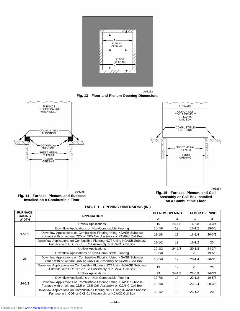
TABLE 1—OPENING DIMENSIONS (IN.)
FURNACECASINGWIDTH
APPLICATIONPLENUM OPENING FLOOR OPENING
A B C D
17-1/2
Upflow Applications 16 24-1/8 16-5/8 24-3/4Downflow Applications on Non-Combustible Flooring 15-7/8 19 16-1/2 19-5/8
Downflow Applications on Combustible Flooring Using KGASB SubbaseFurnace with or without CD5 or CK5 Coil Assembly or KCAKC Coil Box 15-1/8 19 16-3/4 20-3/8
Downflow Applications on Combustible Flooring NOT Using KGASB SubbaseFurnace with CD5 or CK5 Coil Assembly or KCAKC Coil Box 15-1/2 19 16-1/2 20
21
Upflow Applications 19-1/2 24-1/8 20-1/8 24-3/4Downflow Applications on Non-Combustible Flooring 19-3/8 19 20 19-5/8
Downflow Applications on Combustible Flooring Using KGASB SubbaseFurnace with or without CD5 or CK5 Coil Assembly or KCAKC Coil Box 18-5/8 19 20-1/4 20-3/8
Downflow Applications on Combustible Flooring NOT Using KGASB SubbaseFurnace with CD5 or CK5 Coil Assembly or KCAKC Coil Box 19 19 20 20
24-1/2
Upflow Applications 23 24-1/8 23-5/8 24-3/4Downflow Applications on Non-Combustible Flooring 22-7/8 19 23-1/2 19-5/8
Downflow Applications on Combustible Flooring Using KGASB SubbaseFurnace with or without CD5 or CK5 Coil Assembly or KCAKC Coil Box 22-1/8 19 23-3/4 20-3/8
Downflow Applications on Combustible Flooring NOT Using KGASB SubbaseFurnace with CD5 or CK5 Coil Assembly or KCAKC Coil Box 22-1/2 19 23-1/2 20
Fig. 14—Furnace, Plenum, and SubbaseInstalled on a Combustible Floor
A96285
DOWNFLOW SUBBASE
SHEET METAL PLENUMFLOOR
OPENING
FURNACE (OR COIL CASING
WHEN USED)
COMBUSTIBLE FLOORING
Fig. 13—Floor and Plenum Opening DimensionsA96283
PLENUM OPENING
C
A
B D
FLOOR OPENING
Fig. 15—Furnace, Plenum, and CoilAssembly or Coil Box Installed
on a Combustible Floor
A96284
CD5 OR CK5 COIL ASSEMBLY
OR KCAKC COIL BOX
FURNACE
SHEET METAL PLENUM
FLOOR OPENING
COMBUSTIBLE FLOORING
—14—
Downloaded from www.Manualslib.com manuals search engine

III. INSTALLATION IN HORIZONTAL APPLICATIONS
These furnaces can be installed horizontally in either horizontalleft or right discharge position. In a crawlspace, furnace can eitherbe hung from floor joist or installed on suitable blocks or pad.Furnace can be suspended from each corner by hanger bolts andangle iron supports. (See Fig. 17.) Cut hanger bolts (4 each 3/8-in.all-thread rod) to desired length. Use 1 X 3/8-in. flat washers,3/8-in. lockwashers, and 3/8-in. nuts on hanger rods as shown inFig. 17. Dimples are provided for hole locations. (See Fig. 2.)
CAUTION: The entire length of furnace MUST besupported when furnace is used in a horizontal position toensure proper draining. When suspended, bottom bracesupports sides and center blower shelf. When unit issupported from the ground, blocks or pad should supportsides and center blower shelf area.
Fig. 16—Duct FlangesA93029
NO
YES
YES
PERFORATED DISCHARGE DUCT FLANGE
210° MIN
Fig. 17—Crawlspace Horizontal ApplicationA93304
NOTES:
ANGLE IRON OR EQUIVALENT
(B)
(A) ROD LOCATION USING DIMPLE LOCATORS (SEE DIMENSIONAL DWG FOR LOCATIONS)
13/16-IN. MAX ALTERNATE SUPPORT LOCATION FROM BACK
ALTERNATE SUPPORT LOCATION 4-IN. MIN 8-IN. MAX
3⁄8-IN. ROD
(A) (B)
(A)(B)
(B)(A)
1. A 1 In. clearance minimum between top of furnace and combustible material. 2. The entire length of furnace must be supported when furnace is used in horizontal position to ensure proper drainage.
(A) PREFERRED ROD LOCATION (B) ALTERNATE ROD LOCATION
DRAIN
5 3⁄4″
3/8-IN. HEX NUT & WASHER (4)
REQD PER ROD
—15—
→
→
Downloaded from www.Manualslib.com manuals search engine
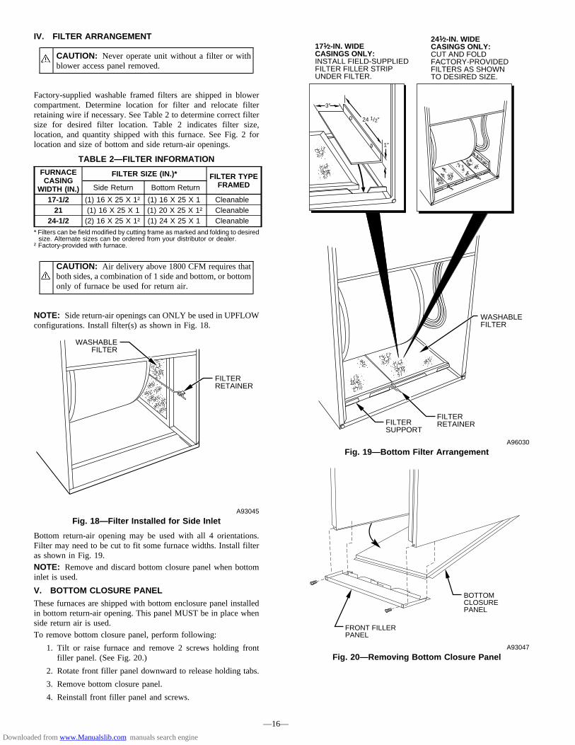
IV. FILTER ARRANGEMENT
CAUTION: Never operate unit without a filter or withblower access panel removed.
Factory-supplied washable framed filters are shipped in blowercompartment. Determine location for filter and relocate filterretaining wire if necessary. See Table 2 to determine correct filtersize for desired filter location. Table 2 indicates filter size,location, and quantity shipped with this furnace. See Fig. 2 forlocation and size of bottom and side return-air openings.
CAUTION: Air delivery above 1800 CFM requires thatboth sides, a combination of 1 side and bottom, or bottomonly of furnace be used for return air.
NOTE: Side return-air openings can ONLY be used in UPFLOWconfigurations. Install filter(s) as shown in Fig. 18.
Bottom return-air opening may be used with all 4 orientations.Filter may need to be cut to fit some furnace widths. Install filteras shown in Fig. 19.NOTE: Remove and discard bottom closure panel when bottominlet is used.
V. BOTTOM CLOSURE PANEL
These furnaces are shipped with bottom enclosure panel installedin bottom return-air opening. This panel MUST be in place whenside return air is used.To remove bottom closure panel, perform following:
1. Tilt or raise furnace and remove 2 screws holding frontfiller panel. (See Fig. 20.)
2. Rotate front filler panel downward to release holding tabs.
3. Remove bottom closure panel.
4. Reinstall front filler panel and screws.
TABLE 2—FILTER INFORMATION
FURNACECASING
WIDTH (IN.)
FILTER SIZE (IN.)* FILTER TYPEFRAMEDSide Return Bottom Return
17-1/2 (1) 16 X 25 X 1† (1) 16 X 25 X 1 Cleanable21 (1) 16 X 25 X 1 (1) 20 X 25 X 1† Cleanable
24-1/2 (2) 16 X 25 X 1† (1) 24 X 25 X 1 Cleanable
* Filters can be field modified by cutting frame as marked and folding to desiredsize. Alternate sizes can be ordered from your distributor or dealer.
† Factory-provided with furnace.
Fig. 18—Filter Installed for Side InletA93045
FILTER RETAINER
WASHABLE FILTER
Fig. 19—Bottom Filter ArrangementA96030
WASHABLE FILTER
FILTER SUPPORT
FILTER RETAINER
241⁄2-IN. WIDE CASINGS ONLY: CUT AND FOLD FACTORY-PROVIDED FILTERS AS SHOWN TO DESIRED SIZE.
171⁄2-IN. WIDE CASINGS ONLY: INSTALL FIELD-SUPPLIED FILTER FILLER STRIP UNDER FILTER.
1″
24 1/2″
3″
Fig. 20—Removing Bottom Closure PanelA93047
BOTTOM CLOSURE PANEL
FRONT FILLER PANEL
—16—
Downloaded from www.Manualslib.com manuals search engine

VI. GAS PIPING
Gas piping must be installed in accordance with national and localcodes. Refer to current edition of NFGC. Canadian installationsmust be made in accordance with NSCNGPIC and all authoritieshaving jurisdiction. Gas supply line should be a separate linerunning directly from meter to furnace, if possible. Refer to Table3 for recommended gas pipe sizing. Risers must be used to connectto furnace and to meter. Support all gas piping with appropriatestraps, hangers, etc. Use a minimum of 1 hanger every 6 ft. Jointcompound (pipe dope) should be applied sparingly and only tomale threads of joints. Pipe dope must be resistant to propane gas.
CAUTION: Connect gas pipe to furnace using a backupwrench to avoid damaging gas controls.
WARNING: Gas valve shutoff switch MUST be facingforward or tilted upward. Failure to follow this warningcould result in property damage or death.
WARNING: Never purge a gas line into a combustionchamber. Never use matches, candles, flame, or othersources of ignition for purpose of checking leakage. Usea soap-and-water solution to check for leakage. A failureto follow this warning could result in fire, explosion,personal injury, or death.
WARNING: Use proper length of pipe to avoid stress ongas control manifold. Failure to follow this warning couldresult in a gas leak resulting in fire, explosion, personalinjury, or death.
Install a sediment trap in riser leading to furnace. Trap can beinstalled by connecting a tee to riser leading to furnace sostraight-through section of tee is vertical. Then connect a cappednipple into lower end of tee. Capped nipple should extend belowlevel of gas controls. Place a ground joint union between gascontrol manifold and manual gas shutoff valve. (See Fig. 21.)
CAUTION: If a flexible connector is required or al-lowed by authority having jurisdiction, black iron pipeshall be installed at gas valve and extend a minimum of2 in. outside furnace casing.
An accessible manual shutoff valve MUST be installed upstreamof furnace gas controls and within 6 ft of furnace. A 1/8-in. NPT
plugged tapping, accessible for test gage connection, MUST beinstalled immediately upstream of gas supply connection tofurnace and downstream of manual shutoff valve.NOTE: The gas valve inlet press tap connection is suitable to useas test gage connection providing test pressure DOES NOT exceedmaximum 0.5 psig (14-in. wc) stated on gas valve. (See Fig. 45.)Piping should be pressure tested in accordance with local andnational plumbing and gas codes before furnace is attached. InCanada, refer to current edition of NSCNGPIC. If pressureexceeds 0.5 psig (14-in. wc), gas supply pipe must be disconnectedfrom furnace and capped before pressure test. If test pressure isequal to or less than 0.5 psig (14-in. wc), turn off electric shutoffswitch located on gas valve before test. It is recommended thatground joint union be loosened before pressure testing. After allconnections have been made, purge lines and check for leakage.
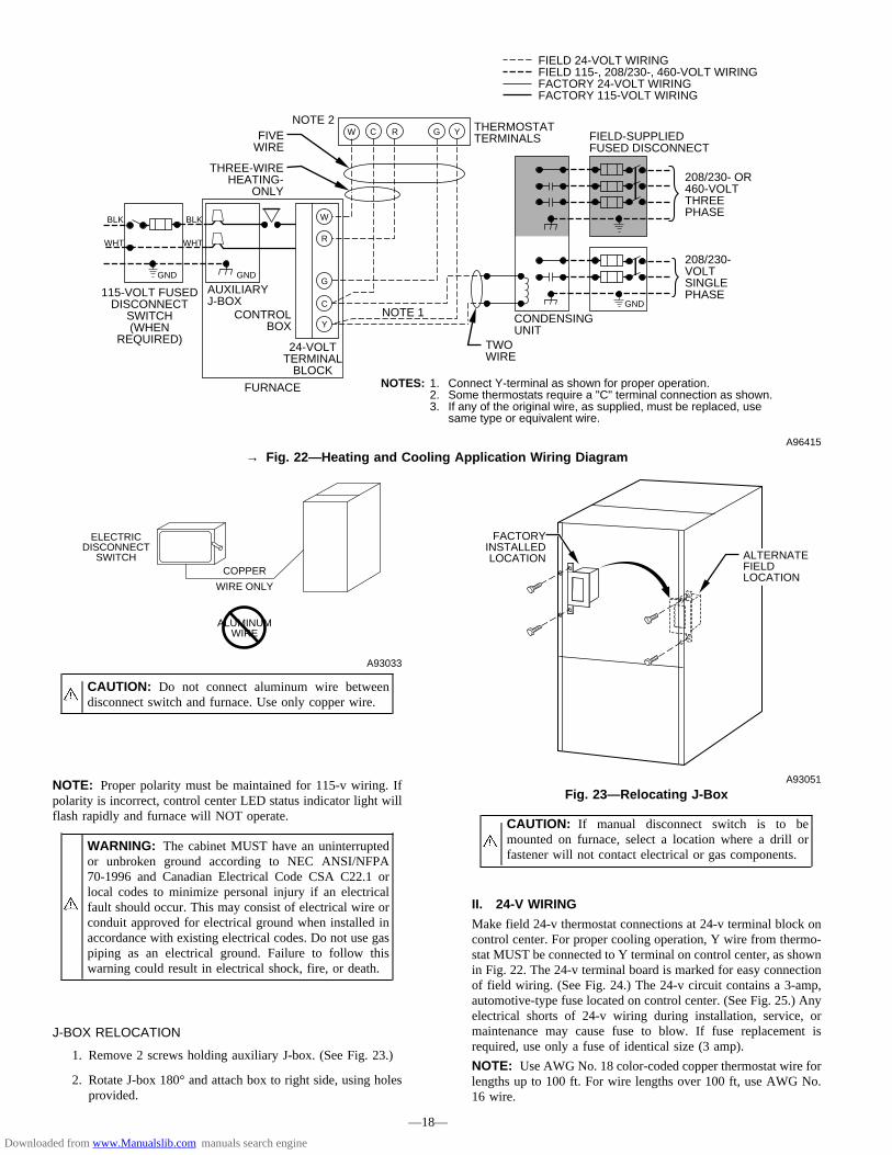
ELECTRICAL CONNECTIONSSee Fig. 22 for field wiring diagram showing typical field 115-vand 24-v wiring. Check all factory and field electrical connectionsfor tightness.
WARNING: Blower access panel door switch opens115-v power to control center. No component operationcan occur. Do not bypass or close switch with panelremoved. Failure to follow this warning could result inpersonal injury or death.
CAUTION: Furnace control must be grounded forproper operation or control will lock out. Control isgrounded through green wire routed to gas valve andburner box screw.
I. 115-V WIRING
Before proceeding with electrical connections, make certain thatvoltage, frequency, and phase correspond to that specified on unitrating plate. Also, check to be sure that service provided by utilityis sufficient to handle load imposed by this equipment. Refer torating plate or Table 4 for equipment electrical specifications.Make all electrical connections in accordance with NationalElectrical Code (NEC) ANSI/NFPA 70-1996 and any local codesor ordinances that might apply. For Canadian installations, allelectrical connections must be made in accordance with CanadianElectrical Code CSA C22.1 or subauthorities having jurisdiction.Use a separate, fused branch electrical circuit containing a properlysized fuse or circuit breaker for this furnace. See Table 4 for wiresize and fuse specifications. A disconnecting means must belocated within sight from and readily accessible to furnace.
TABLE 3—MAXIMUM CAPACITY OF PIPE*
NOMINALIRONPIPESIZE(IN.)
INTERNALDIAMETER
(IN.)
LENGTH OF PIPE (FT)
10 20 30 40 50
1/2 0.622 175 120 97 82 733/4 0.824 360 250 200 170 1511 1.049 680 465 375 320 285
1-1/4 1.380 1400 950 770 660 5801-1/2 1.610 2100 1460 1180 990 900
→ * Cubic ft of gas per hr for gas pressures of 0.5 psig (14-in. wc) or less, anda pressure drop of 0.5-in. wc (based on a 0.60 specific gravity gas).Ref: Table 10-2 NFPA 54-1996.
Fig. 21—Typical Gas Pipe ArrangementA93324
UNION
SEDIMENT TRAP
MANUAL SHUTOFF VALVE (REQUIRED)
GAS SUPPLY
—17—
Downloaded from www.Manualslib.com manuals search engine
NOTE: Proper polarity must be maintained for 115-v wiring. Ifpolarity is incorrect, control center LED status indicator light willflash rapidly and furnace will NOT operate.
WARNING: The cabinet MUST have an uninterruptedor unbroken ground according to NEC ANSI/NFPA70-1996 and Canadian Electrical Code CSA C22.1 orlocal codes to minimize personal injury if an electricalfault should occur. This may consist of electrical wire orconduit approved for electrical ground when installed inaccordance with existing electrical codes. Do not use gaspiping as an electrical ground. Failure to follow thiswarning could result in electrical shock, fire, or death.
J-BOX RELOCATION
1. Remove 2 screws holding auxiliary J-box. (See Fig. 23.)
2. Rotate J-box 180° and attach box to right side, using holesprovided.
CAUTION: If manual disconnect switch is to bemounted on furnace, select a location where a drill orfastener will not contact electrical or gas components.
II. 24-V WIRING
Make field 24-v thermostat connections at 24-v terminal block oncontrol center. For proper cooling operation, Y wire from thermo-stat MUST be connected to Y terminal on control center, as shownin Fig. 22. The 24-v terminal board is marked for easy connectionof field wiring. (See Fig. 24.) The 24-v circuit contains a 3-amp,automotive-type fuse located on control center. (See Fig. 25.) Anyelectrical shorts of 24-v wiring during installation, service, ormaintenance may cause fuse to blow. If fuse replacement isrequired, use only a fuse of identical size (3 amp).
NOTE: Use AWG No. 18 color-coded copper thermostat wire forlengths up to 100 ft. For wire lengths over 100 ft, use AWG No.16 wire.
→ Fig. 22—Heating and Cooling Application Wiring DiagramA96415
115-VOLT FUSED DISCONNECT
SWITCH (WHEN
REQUIRED)
AUXILIARY J-BOX
CONTROL BOX
24-VOLT TERMINAL
BLOCK
THREE-WIRE HEATING-
ONLY
FIVE WIRE
NOTE 1
NOTE 2FIELD-SUPPLIED FUSED DISCONNECT
CONDENSING UNIT
TWO WIRE
FURNACE
R
G
C
W C R G Y
GND
GND
FIELD 24-VOLT WIRING FIELD 115-, 208/230-, 460-VOLT WIRING FACTORY 24-VOLT WIRING FACTORY 115-VOLT WIRING
208/230- OR 460-VOLT THREE PHASE
208/230- VOLT SINGLE PHASE
WHT
BLK
WHT
BLK
NOTES: Connect Y-terminal as shown for proper operation. Some thermostats require a "C" terminal connection as shown. If any of the original wire, as supplied, must be replaced, use same type or equivalent wire.
W
Y
GND
THERMOSTAT TERMINALS
1. 2.�3.
CAUTION: Do not connect aluminum wire betweendisconnect switch and furnace. Use only copper wire.
A93033
COPPER
WIRE ONLY
ELECTRIC DISCONNECT
SWITCH
ALUMINUM WIRE
Fig. 23—Relocating J-BoxA93051
ALTERNATE FIELD LOCATION
FACTORY INSTALLED LOCATION
—18—
Downloaded from www.Manualslib.com manuals search engine

Fig.24—Wiring
Diagram
A95087
PC
B
BLO
WE
R O
FF D
ELA
YS
ELE
CTI
ON
CH
AR
T
90S
EC
135
SE
C
180
SE
C
225
SE
C
GV
R
HI/L
OR
ELA
Y
SE
C-1
SE
C-2
WH
TPL1
32
1
65
49
87
LED
TE
ST
/TW
IN
BLO
WE
RO
FFD
ELA
Y
G R Y W C HU
M
HS
IRID
RB
LWR
BLO
WE
RS
PE
ED
SE
LEC
TFU1 C
OO
L
HE
AT
L2P
L3P
L2V
AC
120
L1P
R1
1 2
1 2 3P
R2
24 V
AC
-3A
FUS
E SP
AR
E-2
SP
AR
E-1
EA
C-1
EA
C-2 C
1.5 AMP
12
PL5
WH
T
BR
N
GR
N
BLK
IDM
BR
N
CA
P -2
WHT
WHT
BLK
BLK
HS
I
AU
X
OL
M
BLK
WH
TW
HT
(C
OM
)
RE
D
(LO
)
BLU
(ME
D L
O)
NO
TE #
8
OL
STA
RT
BLW
M
YE
L (M
ED
HI)
BLK
(H
I)
BR
N
BR
N
TRAN
BLU RE
D
BLK WH
T WH
T (C
OM
)
GR
N
CA
P -1
GR
N2-
CR
ED
FSE
NO
TE #
5
1-M
3-P G
VFR
S
BLU
YE
L
RE
D
NO
TE #
6
LS
RE
D
OR
N
PR
S(W
HE
N U
SE
D)
LGP
S
FUS
ED
DIS
CO
NN
EC
TS
WIT
CH
(WH
EN
RE
Q’D
)N
OTE
#4
WH
T
GR
NG
RNJB
LEG
EN
DB
LWR
BLO
WE
R M
OTO
R R
ELA
Y, S
PS
T-(N
.O.)
BLW
MB
LOW
ER
MO
TOR
CA
PC
AP
AC
ITO
RC
PU
MIC
RO
PR
OC
ES
SO
R A
ND
CIR
CU
ITR
YE
AC
-1E
LEC
TRO
NIC
AIR
CLE
AN
ER
CO
NN
EC
TIO
N (1
15 V
AC
1.5
AM
P M
AX
.)E
AC
-2E
LEC
TRO
NIC
AIR
CLE
AN
ER
CO
NN
EC
TIO
N (C
OM
MO
N)
FRS
FLA
ME
RO
LLO
UT
SW
. -M
AN
UA
L R
ES
ET,
SP
ST-
(N.C
.)FS
EFL
AM
E P
RO
VIN
G E
LEC
TRO
DE
FU1
FUS
E, 3
AM
P, A
UTO
MO
TIV
E B
LAD
E T
YP
E, F
AC
TOR
Y IN
STA
LLE
DFU
2FU
SE
OR
CIR
CU
IT B
RE
AK
ER
CU
RR
EN
T IN
TER
RU
PT
DE
VIC
E(F
IELD
INS
TALL
ED
& S
UP
PLI
ED
)G
VG
AS
VA
LVE
-RE
DU
ND
AN
T O
PE
RA
TOR
SG
VR
GA
S V
ALV
E R
ELA
Y, D
PS
T-(N
.O.)
HI/L
OB
LOW
ER
MO
TOR
SP
EE
D C
HA
NG
E R
ELA
Y, S
PD
TH
SI
HO
T S
UR
FAC
E IG
NIT
OR
(115
VA
C)
HS
IRH
OT
SU
RFA
CE
IGN
ITO
R R
ELA
Y, S
PS
T-(N
.O.)
HU
M24
VA
C H
UM
IDIF
IER
CO
NN
EC
TIO
N (.
5 A
MP
. MA
X.)
IDM
IND
UC
ED
DR
AFT
MO
TOR
IDR
IND
UC
ED
DR
AFT
RE
LAY
, SP
ST-
(N.O
.)IL
KB
LOW
ER
AC
CE
SS
PA
NE
L IN
TER
LOC
K S
WIT
CH
, SP
ST-
(N.O
.)JB
JUN
CTI
ON
BO
XLE
DLI
GH
T-E
MIT
TIN
G D
IOD
E F
OR
STA
TUS
CO
DE
SLG
PS
LOW
GA
S P
RE
SS
UR
E S
WIT
CH
, SP
ST-
(N.O
.)LS
LIM
IT S
WIT
CH
, AU
TO R
ES
ET,
SP
ST(
N.C
.)O
LA
UTO
-RE
SE
T IN
TER
NA
L M
OTO
R O
VE
RLO
AD
TE
MP
. SW
.P
CB
PR
INTE
D C
IRC
UIT
BO
AR
D
PL1
9-C
IRC
UIT
CO
NN
ECTO
RPL
22-
CIR
CU
IT P
CB
CO
NN
ECTO
RPL
33-
CIR
CU
IT ID
M C
ON
NEC
TOR
PL4
3-C
IRC
UIT
IDM
EXT
ENSI
ON
CO
NN
ECTO
RPL
52-
CIR
CU
IT H
SI/P
CB
CO
NN
ECTO
RPR
SPR
ESSU
RE
SWIT
CH
, SPS
T-(N
.O.)
SW1
& 2
BLO
WER
OFF
DEL
AYTE
ST/T
WIN
CO
MPO
NEN
T TE
ST &
TW
IN T
ERM
INAL
TRAN
TRAN
SFO
RM
ER-1
15VA
C/2
4VAC
JUN
CTI
ON
UN
MAR
KED
TER
MIN
AL
PCB
TER
MIN
AL
FAC
TOR
Y W
IRIN
G (1
15VA
C)
FAC
TOR
Y W
IRIN
G (2
4VAC
)
FIEL
D W
IRIN
G (1
15VA
C)
FIEL
D W
IRIN
G (2
4VAC
)
CO
ND
UC
TOR
ON
PC
B
FIEL
D W
IRIN
G T
ERM
INAL
FIEL
D G
RO
UN
D
EQU
IPM
ENT
GR
OU
ND
FIEL
D S
PLIC
E
PLU
G R
ECEP
TAC
LE
L1
L1
BLW
RH
I/LO
TO 1
15VA
C F
IELD
DIS
CO
NN
ECT
NO
TE #
4
EQU
IPM
ENT
GR
OU
ND
SPAR
E-1
HEA
TSP
ARE-
2
CO
OL
NO
TE #
8
CO
M
HSI
REA
C-1
STAR
TO
L
CO
MHI
MED
HI
MED
LO
LO
BLW
M
SCH
EMAT
IC D
IAG
RAM
(NAT
UR
AL G
AS &
PR
OPA
NE)
EAC
-2
11
HSI
2PL
52
PL2
3
PL3
PR2
115V
ACPR
1
TRAN
24VA
C
1 2
BRNM
IDR
TEST
/TW
INFU
1N
OTE
#7
IDM
OL AU
X
BRN
CAP
-2
CAP
-1
L2
FRS
LS
LGPS
(WH
EN U
SED
)
NO
TE #
6PL
1PR
S
GV 2-
C1-
M3-P
NO
TE #
58
FSE
965
CPU
HSI
RID
RBL
WR
Y G CR W
GVR
-2
SEC
-1
HI/L
OG
VR
GVR
-1
SEC
-2
NO
TES:
3228
54-1
01 R
EV. C
1.IF
AN
Y O
F TH
E O
RIG
INAL
EQ
UIP
MEN
T W
IRE
IS R
EPLA
CED
USE
WIR
E R
ATED
FO
R 1
05°C
.2.
IND
UC
ER (I
DM
) AN
D B
LOW
ER (B
LWM
) MO
TOR
S C
ON
TAIN
INTE
RN
ALAU
TO-R
ESET
TH
ERM
AL O
VER
LOAD
SW
ITC
HES
(OL)
.3.
BLO
WER
MO
TOR
SPE
ED S
ELEC
TIO
NS
ARE
FOR
AVE
RAG
E C
ON
DIT
ION
S, S
EE IN
STAL
LATI
ON
INST
RU
CTI
ON
S FO
R D
ETAI
LS O
N O
PTIM
UM
SPE
ED S
ELEC
TIO
N.
4.U
SE O
NLY
CO
PPER
WIR
E BE
TWEE
N T
HE
DIS
CO
NN
ECT
SWIT
CH
AN
D T
HE
FUR
NAC
E JU
NC
TIO
N B
OX
(JB)
.5.
THIS
WIR
E M
UST
BE
CO
NN
ECTE
D T
O F
UR
NAC
E SH
EETM
ETAL
FO
R C
ON
TRO
L TO
PR
OVE
FLAM
E.6.
FAC
TOR
Y C
ON
NEC
TED
WH
EN L
GPS
NO
T U
SED
.7.
REP
LAC
E O
NLY
WIT
H A
3 A
MP
FUSE
.8.
YELL
OW
LEA
D N
OT
ON
ALL
MO
TOR
S.9.
BLO
WER
-ON
DEL
AY, G
AS H
EATI
NG
60
SEC
ON
DS,
CO
OLI
NG
OR
HEA
T PU
MP
2 SE
CO
ND
S.10
.BL
OW
ER-O
FF D
ELAY
, GAS
HEA
TIN
G 9
0, 1
35, 1
80 O
R 2
25 S
ECO
ND
S, C
OO
LIN
G O
RH
EAT
PUM
P 90
SEC
ON
DS.
(135
SEC
ON
DS
ON
LY O
N S
OM
E M
OD
ELS)
11.
IGN
ITIO
N-L
OC
KOU
T W
ILL
OC
CU
R A
FTER
FO
UR
CO
NSE
CU
TIVE
UN
SUC
CES
SFU
LTR
IALS
-FO
R-IG
NIT
ION
. CO
NTR
OL
WIL
L AU
TO-R
ESET
AFT
ER T
HR
EE H
OU
RS.
12.
SOM
E M
OD
ELS
MAY
HAV
E SP
ADE
QU
ICK
CO
NN
ECT
TER
MIN
ALS.
BLK
OM
SW2
SW1
OM
2347 1O
M
HU
M
12
3
WHT
BLK
GRN
PL4
PL4
231
NEU
TRAL
NEU
TRAL
WH
T
ILK
FU2
BLK
L1
ILK
(NO
T O
N A
LL M
OD
ELS
)
SEE
NO
TE #
10
NO
TE #
12
—19—
Downloaded from www.Manualslib.com manuals search engine
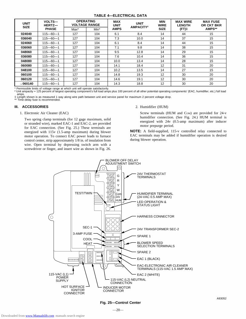
III. ACCESSORIES
1. Electronic Air Cleaner (EAC)
Two spring clamp terminals (for 12 gage maximum, solidor stranded wire), marked EAC-1 and EAC-2, are providedfor EAC connection. (See Fig. 25.) These terminals areenergized with 115v (1.5-amp maximum) during blowermotor operation. To connect EAC power leads to furnacecontrol center, strip approximately 1/8 in. of insulation fromwire. Open terminal by depressing switch arm with ascrewdriver or finger, and insert wire as shown in Fig. 26.
2. Humidifier (HUM)
Screw terminals (HUM and COM) are provided for 24-vhumidifier connection. (See Fig. 24.) HUM terminal isenergized with 24v (0.5-amp maximum) after inducermotor prepurge period.
NOTE: A field-supplied, 115-v controlled relay connected toEAC terminals may be added if humidifier operation is desiredduring blower operation.
TABLE 4—ELECTRICAL DATA
UNITSIZE
VOLTS—HERTZ—PHASE
OPERATINGVOLTAGE RANGE
MAXUNITAMPS
UNITAMPACITY†
MINWIRESIZE
MAX WIRELENGTH(FT)‡
MAX FUSEOR CKT BKR
AMPS**Max* Min*024040 115—60—1 127 104 6.1 8.4 14 44 15036040 115—60—1 127 104 7.3 10.0 14 37 15024060 115—60—1 127 104 6.1 8.4 14 44 15036060 115—60—1 127 104 7.1 9.8 14 38 15048060 115—60—1 127 104 9.5 12.8 14 29 15036080 115—60—1 127 104 7.6 10.4 14 36 15048080 115—60—1 127 104 10.0 13.4 14 28 15060080 115—60—1 127 104 14.1 18.4 12 31 20048100 115—60—1 127 104 10.2 13.5 14 27 15060100 115—60—1 127 104 14.8 19.3 12 30 20060120 115—60—1 127 104 14.6 19.1 12 30 20
→060140 115—60—1 127 104 14.3 18.8 12 30 20
* Permissible limits of voltage range at which unit will operate satisfactorily.† Unit ampacity = 125 percent of largest operating component’s full load amps plus 100 percent of all other potential operating components’ (EAC, humidifier, etc.) full loadamps.
‡ Length shown is as measured 1 way along wire path between unit and service panel for maximum 2 percent voltage drop.** Time-delay fuse is recommended.
Fig. 25—Control CenterA93052
G
R
Y
W
3-AMP FUSE
Com 24V
HUMIDIFIER TERMINAL (24-VAC 0.5 AMP MAX)
LED OPERATION & STATUS LIGHT
HARNESS CONNECTOR
24V TRANSFORMER SEC-2
SPARE 1
SPARE 2
EAC 1 (BLACK)
EAC-ELECTRONIC AIR CLEANER TERMINALS (115-VAC 1.5 AMP MAX)
EAC 2 (WHITE)
115-VAC (L2) NEUTRAL CONNECTION
24V THERMOSTAT TERMINALS
BLOWER SPEED SELECTION TERMINALS
INDUCER MOTOR CONNECTOR
115-VAC (L1) POWER SUPPLY
HOT SURFACE IGNITOR
CONNECTOR
HEATCOOL
BLOWER OFF DELAY ADJUSTMENT SWITCH
SEC-1
TEST/TWIN
HUM
—20—
Downloaded from www.Manualslib.com manuals search engine
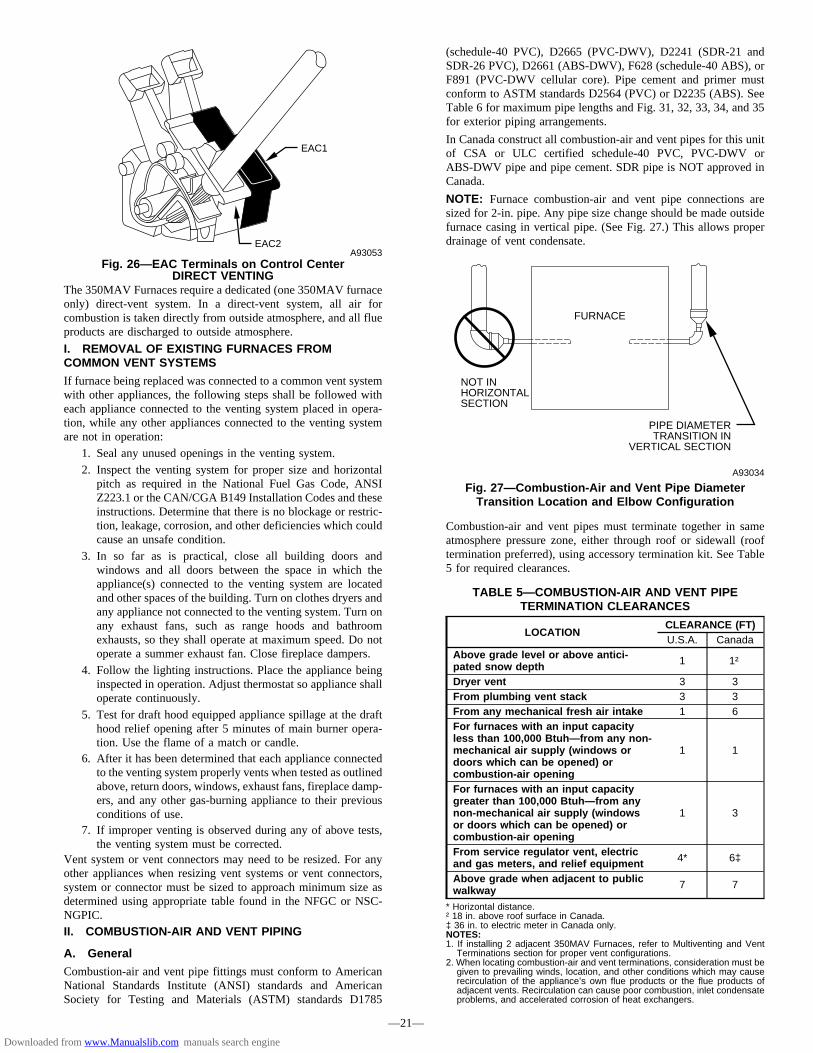
DIRECT VENTINGThe 350MAV Furnaces require a dedicated (one 350MAV furnaceonly) direct-vent system. In a direct-vent system, all air forcombustion is taken directly from outside atmosphere, and all flueproducts are discharged to outside atmosphere.
I. REMOVAL OF EXISTING FURNACES FROMCOMMON VENT SYSTEMS
If furnace being replaced was connected to a common vent systemwith other appliances, the following steps shall be followed witheach appliance connected to the venting system placed in opera-tion, while any other appliances connected to the venting systemare not in operation:
1. Seal any unused openings in the venting system.2. Inspect the venting system for proper size and horizontal
pitch as required in the National Fuel Gas Code, ANSIZ223.1 or the CAN/CGA B149 Installation Codes and theseinstructions. Determine that there is no blockage or restric-tion, leakage, corrosion, and other deficiencies which couldcause an unsafe condition.
3. In so far as is practical, close all building doors andwindows and all doors between the space in which theappliance(s) connected to the venting system are locatedand other spaces of the building. Turn on clothes dryers andany appliance not connected to the venting system. Turn onany exhaust fans, such as range hoods and bathroomexhausts, so they shall operate at maximum speed. Do notoperate a summer exhaust fan. Close fireplace dampers.
4. Follow the lighting instructions. Place the appliance beinginspected in operation. Adjust thermostat so appliance shalloperate continuously.
5. Test for draft hood equipped appliance spillage at the drafthood relief opening after 5 minutes of main burner opera-tion. Use the flame of a match or candle.
6. After it has been determined that each appliance connectedto the venting system properly vents when tested as outlinedabove, return doors, windows, exhaust fans, fireplace damp-ers, and any other gas-burning appliance to their previousconditions of use.
7. If improper venting is observed during any of above tests,the venting system must be corrected.
Vent system or vent connectors may need to be resized. For anyother appliances when resizing vent systems or vent connectors,system or connector must be sized to approach minimum size asdetermined using appropriate table found in the NFGC or NSC-NGPIC.II. COMBUSTION-AIR AND VENT PIPING
A. General
Combustion-air and vent pipe fittings must conform to AmericanNational Standards Institute (ANSI) standards and AmericanSociety for Testing and Materials (ASTM) standards D1785
(schedule-40 PVC), D2665 (PVC-DWV), D2241 (SDR-21 andSDR-26 PVC), D2661 (ABS-DWV), F628 (schedule-40 ABS), orF891 (PVC-DWV cellular core). Pipe cement and primer mustconform to ASTM standards D2564 (PVC) or D2235 (ABS). SeeTable 6 for maximum pipe lengths and Fig. 31, 32, 33, 34, and 35for exterior piping arrangements.
In Canada construct all combustion-air and vent pipes for this unitof CSA or ULC certified schedule-40 PVC, PVC-DWV orABS-DWV pipe and pipe cement. SDR pipe is NOT approved inCanada.
NOTE: Furnace combustion-air and vent pipe connections aresized for 2-in. pipe. Any pipe size change should be made outsidefurnace casing in vertical pipe. (See Fig. 27.) This allows properdrainage of vent condensate.
Combustion-air and vent pipes must terminate together in sameatmosphere pressure zone, either through roof or sidewall (rooftermination preferred), using accessory termination kit. See Table5 for required clearances.
Fig. 26—EAC Terminals on Control CenterA93053
EAC2
EAC1
Fig. 27—Combustion-Air and Vent Pipe DiameterTransition Location and Elbow Configuration
A93034
FURNACE
PIPE DIAMETER TRANSITION IN
VERTICAL SECTION
NOT IN HORIZONTAL SECTION
TABLE 5—COMBUSTION-AIR AND VENT PIPETERMINATION CLEARANCES
LOCATIONCLEARANCE (FT)U.S.A. Canada
Above grade level or above antici-pated snow depth 1 1†
Dryer vent 3 3From plumbing vent stack 3 3From any mechanical fresh air intake 1 6For furnaces with an input capacityless than 100,000 Btuh—from any non-mechanical air supply (windows ordoors which can be opened) orcombustion-air opening
1 1
For furnaces with an input capacitygreater than 100,000 Btuh—from anynon-mechanical air supply (windowsor doors which can be opened) orcombustion-air opening
1 3
From service regulator vent, electricand gas meters, and relief equipment 4* 6‡
Above grade when adjacent to publicwalkway 7 7
* Horizontal distance.† 18 in. above roof surface in Canada.‡ 36 in. to electric meter in Canada only.NOTES:1. If installing 2 adjacent 350MAV Furnaces, refer to Multiventing and VentTerminations section for proper vent configurations.
2. When locating combustion-air and vent terminations, consideration must begiven to prevailing winds, location, and other conditions which may causerecirculation of the appliance’s own flue products or the flue products ofadjacent vents. Recirculation can cause poor combustion, inlet condensateproblems, and accelerated corrosion of heat exchangers.
—21—
Downloaded from www.Manualslib.com manuals search engine

Furnace combustion-air and vent pipe connections must be at-tached as shown in Fig. 28. Combustion-air intake plug fitting andinducer housing alternate vent cap may need to be relocated insome applications.
NOTE: Slope combustion-air and vent pipes a minimum of 1/4in. per linear ft with no sags between hangers.
CAUTION: When combustion-air pipe is installedabove a suspended ceiling, pipe must be insulated with3/8-in. thick Armaflex-type insulation. Combustion-airpipe should also be insulated when it passes throughwarm, humid space.
CAUTION: When vent pipe is exposed to temperaturesbelow freezing, such as when it passes through anunheated space or when a chimney is used as a raceway,pipe must be insulated as shown in Table 7 withArmaflex-type insulation.
CAUTION: Combustion air must not be taken frominside structure because inside air is frequently contami-nated by halogens, which include fluorides, chlorides,bromides, and iodides. These elements are found inaerosols, detergents, bleaches, cleaning solvents, salts, airfresheners, adhesives, paint, and other household prod-ucts. Locate combustion-air inlet as far as possible fromswimming pool and swimming pool pump house.Excessive exposure to contaminated combustion air willresult in safety and performance related problems.
WARNING: Solvent cements are combustible. Keepaway from heat, sparks, and open flame. Use only inwell-ventilated areas. Avoid breathing in vapor or allow-ing contact with skin or eyes. Failure to follow thiswarning could result in fire, property damage, personalinjury, or death.
WARNING: All combustion-air and vent pipes must beairtight and watertight. Pipes must also terminate exactlyas shown in Fig. 31, 32, 33, 34, or 35. Failure to followthis warning could result in property damage, personalinjury, or death.
NOTE: The minimum combustion-air and vent pipe length (each)for these furnaces is 5 ft. Short pipe lengths (5-8 ft) may dischargewater droplets. These droplets may be undesirable, and a 12-in.minimum offset pipe section is recommended, as shown in Fig. 29,to reduce excessive droplets from exiting vent pipe outlet.B. Combustion-Air and Vent Pipe Diameter
Determine combustion-air and vent pipe diameter.1. Using Table 6, individually determine the combustion-air
and vent pipe diameters. Pick the larger of these 2 pipediameters and use this diameter for both combustion-air andvent pipes.
2. When installing vent systems of short pipe length, use thesmallest allowable pipe diameter. Do not use pipe sizegreater than required or incomplete combustion, flamedisturbance, or flame sense lockout may occur.
NOTE: Do not count elbows or pipe sections in terminations orwithin furnace. See shaded areas in Fig. 31, 32, 33, 34, and 35.
EXAMPLE:An 036080 size furnace located in Indianapolis, elevation650 ft above sea level, could be installed in an applicationrequiring 3 elbows and 32 ft of vent pipe, along with 5elbows and 34 ft of combustion-air pipe. Table 6 indicatesthis application would allow a 2-in. diameter vent pipe, butrequire a 2-1/2 in. diameter combustion air pipe (2-in. pipeis good for 35 ft with 3 elbows, but only 30 ft with 5elbows). Therefore, 2-1/2 in. diameter pipe must be usedfor both vent and combustion-air pipes since larger requireddiameter must always be used for both pipes. If sameinstallation were in Albuquerque, elevation 5250 ft abovesea level, installation would require 2-1/2 in. vent pipe andcombustion-air pipe. At 5001- to 6000-ft elevation, 2-in.pipe is only good for 17 ft with 5 elbows, and 2-1/2 in. pipeis good for 70 ft with 5 elbows.
C. Combustion-Air and Vent Pipe Attachment
NOTE: All pipe joints must be watertight except attachment ofcombustion-air pipe to inlet housing connection, since it may benecessary to remove pipe for servicing.
1. Attach combustion-air pipe as follows:a. Determine location of combustion-air intake pipe con-
nection to combustion-air intake housing as shown inFig. 28 for application.
b. Reposition combustion-air intake housing plug fitting inappropriate unused intake housing connection.
c. If required, insert perforated disk assembly (factory-supplied in loose parts bag) in intake housing wherecombustion-air intake pipe will be connected. If half diskset is required, install with shoulder of disk against stopin combustion-air inlet.
Fig. 28—Combustion-Air and Vent Pipe ConnectionsA96187
COMBUSTION- AIR
COMBUSTION- AIR
AIR FLOW
VENT
VENT
VENT
AIR FLOW
AIR FLOW
AIR FLOW
UPFLOW DOWNFLOW
HORIZONTAL-LEFT DISCHARGE HORIZONTAL-RIGHT DISCHARGE
Select 1 vent pipe connection and 1 combustion-air pipe connection.
COMBUSTION- AIR
COMBUSTION- AIR
COMBUSTION- AIR
COMBUSTION- AIR
VENT
VENT
VENT
NOTE: Select 1 vent pipe connection and 1 combustion-air pipe connection.
NOTE:
—22—
→
Downloaded from www.Manualslib.com manuals search engine

d. Install pipe support (factory-supplied in loose parts bag)into selected furnace casing combustion-air pipe hole.Pipe support should be positioned at bottom of casinghole.
e. Insert 2-in. diameter pipe into intake housing.
NOTE: A 2-in. diameter pipe must be used within the furnacecasing. Make all pipe diameter transitions outside furnace casing.
f. Drill a 1/8-in. hole in 2-in. combustion-air pipe usinghole in intake housing as a guide.
g. Install a field-supplied No. 6 or No. 8 sheet metal screwinto combustion-air pipe.
NOTE: DO NOT OVERTIGHTEN SCREW. Breakage to intakehousing or fitting may cause air leakage to occur.
NOTE: Do not attach combustion-air intake pipe permanently tocombustion-air intake housing since it may be necessary to removepipe for service of ignitor or flame sensor.
COMBUSTION-AIR INTAKE HOUSING PLUGFITTING
The combustion-air intake plug fitting must be installed inunused combustion-air intake housing. This fitting must beattached by using RTV sealant, or by drilling a 1/8-in. holein fitting, using hole in intake housing as a guide. Install afield-supplied No. 6 or No. 8 sheet metal screw.
NOTE: DO NOT OVERTIGHTEN SCREW. Breakage to intakehousing or fitting may cause air leakage to occur.
A plugged drain connection has been provided on thisfitting for use when moisture is found in combustion-airintake pipe and combustion box.
NOTE: Moisture in combustion-air intake may be result ofimproper termination. Ensure combustion-air intake pipe is similarto that shown in Fig. 31, 32, 33, 34, or 35 so it will not besusceptible to areas where light snow or other sources of moisturecould be pulled in.
If use of this drain connection is desired, drill out fitting’stap plug with a 3/16-in. drill and connect a field-supplied3/8-in. tube. This tube should be routed to open condensatedrain for furnace and A/C (if used), and should be trapped.(See Fig. 30.)
2. Attach vent pipe as follows:
a. Determine location of vent pipe connection to inducerhousing as shown in Fig. 28 for application.
b. Reposition neoprene inducer housing outlet cap andclamp to appropriate unused inducer housing connec-tion. Tighten clamp.
Fig. 29—Short Vent (5 to 8 Ft) SystemA96230
HORIZONTAL TO ROOF HORIZONTAL TO SIDEWALL
VERTICAL TO SIDEWALLVERTICAL TO ROOF
VENT PIPE
COMBUSTION-AIR PIPE COMBUSTION-AIR PIPE
VENT PIPE
COMBUSTION-AIR PIPEVENT PIPE
COMBUSTION-AIR PIPE
VENT PIPE
12″ MIN
12″ MIN
12″ MIN
12″ MIN
NOTE: A 12 In. minimum offset pipe section is recommended with short (5 to 8 ft) vent systems. This recommendation is to reduce excessive condensate droplets from exiting the vent pipe.
—23—
Downloaded from www.Manualslib.com manuals search engine

TABLE 6—MAXIMUM ALLOWABLE PIPE LENGTH (FT)
ALTITUDE UNIT SIZE TERMINATIONTYPE
PIPE DIA(IN.)*
NUMBER OF 90° ELBOWS1 2 3 4 5 6
0 to 2000
024040036040
2 Pipe or 2-In.Concentric
1 5 NA NA NA NA NA1-1/2 70 70 65 60 60 552 70 70 70 70 70 70
024060036060048060
2 Pipe or 2-In.Concentric
1-1/2 20 15 10 5 NA NA
2 70 70 70 70 70 70
036080048080060080
2 Pipe or 2-In.Concentric
1-1/2 10 NA NA NA NA NA2 55 50 35 30 30 20
2-1/2 70 70 70 70 70 70
048100060100
2 Pipe or 3-In.Concentric
2 5 NA NA NA NA NA2-1/2 40 30 20 20 10 NA3 70 70 70 70 70 70
→060120 2 Pipe or 3-In.Concentric
2-1/2 one disk 10 NA NA NA NA NA3† 45 40 35 30 25 20
3† no disk 70 70 70 70 70 704† no disk 70 70 70 70 70 70
→060140 2 Pipe or 3-In.Concentric
2-1/2 one disk 5 NA NA NA NA NA3† one disk 40 35 30 25 20 153† no disk 60 56 52 48 44 404† no disk 70 70 70 70 70 70
ALTITUDE UNIT SIZE TERMINATIONTYPE
PIPE DIA(IN.)*
NUMBER OF 90° ELBOWS1 2 3 4 5 6
2001 to 3000
024040036040
2 Pipe or 2-In.Concentric
1-1/2 67 62 57 52 52 472 70 70 70 70 70 70
024060036060048060
2 Pipe or 2-In.Concentric
1-1/2 17 12 7 NA NA NA
2 70 67 66 61 61 61
036080048080060080
2 Pipe or 2-In.Concentric
2 49 44 30 25 25 15
2-1/2 70 70 70 70 70 70
048100060100
2 Pipe or 3-In.Concentric
2-1/2 35 26 16 16 6 NA3 70 70 70 70 66 61
→060120 2 Pipe or 3-In.Concentric
3 14 9 NA NA NA NA3† no disk 70 70 63 56 50 434† no disk 70 70 70 70 70 70
→060140 2 Pipe or 3-In.Concentric
3† one disk 20 15 10 5 NA NA3† no disk 39 35 31 27 23 194† no disk 70 70 70 70 70 70
ALTITUDE UNIT SIZE TERMINATIONTYPE
PIPE DIA(IN.)*
NUMBER OF 90° ELBOWS1 2 3 4 5 6
3001 to 4000
024040036040
2 Pipe or 2-In.Concentric
1-1/2 64 59 54 49 48 432 70 70 70 70 70 70
024060036060048060
2 Pipe or 2-In.Concentric
1-1/2 16 11 6 NA NA NA
2 68 63 62 57 57 56
036080048080060080
2 Pipe or 2-In.Concentric
2 46 41 28 23 22 13
2-1/2 70 70 70 70 70 70
048100060100
2 Pipe or 3-In.Concentric
2-1/2 33 24 15 14 5 NA3 70 70 70 66 61 56
→060120 2 Pipe or 3-In.Concentric
3† no disk 65 58 51 44 38 314† no disk 70 70 70 70 70 70
→060140 2 Pipe or 3-In.Concentric
3† one disk 11 6 NA NA NA NA3† no disk 30 26 22 18 14 104† no disk 70 70 70 70 70 70
See notes on page 26.
—24—
Downloaded from www.Manualslib.com manuals search engine

TABLE 6—MAXIMUM ALLOWABLE PIPE LENGTH (FT) Continued
ALTITUDE UNIT SIZE TERMINATIONTYPE
PIPE DIA(IN.)*
NUMBER OF 90° ELBOWS1 2 3 4 5 6
4001 to 5000‡
024040036040
2 Pipe or 2-In.Concentric
1-1/2 60 55 50 45 44 392 70 70 70 70 70 70
024060036060048060
2 Pipe or 2-In.Concentric
1-1/2 15 10 5 NA NA NA
2 64 59 58 53 52 52
036080048080060080
2 Pipe or 2-In.Concentric
2 44 39 26 21 20 11
2-1/2 70 70 70 70 70 70
048100060100
2 Pipe or 3-In.Concentric
2-1/2 31 22 13 12 NA NA3 70 70 67 62 57 52
→060120 2 Pipe or 3-In.Concentric
3† no disk 53 46 40 33 26 204† no disk 70 70 70 70 70 70
→060140 2 Pipe or 3-In.Concentric
3† no disk 21 17 13 9 5 NA4† no disk 69 64 59 54 49 44
ALTITUDE UNIT SIZE TERMINATIONTYPE
PIPE DIA(IN.)*
NUMBER OF 90° ELBOWS1 2 3 4 5 6
5001 to 6000‡
024040036040
2 Pipe or 2-In.Concentric
1-1/2 57 52 47 42 40 352 70 70 70 70 70 70
024060036060048060
2 Pipe or 2-In.Concentric
1-1/2 14 9 NA NA NA NA
2 60 55 54 49 48 47
036080048080060080
2 Pipe or 2-In.Concentric
2 41 36 23 18 17 8
2-1/2 70 70 70 70 70 70
048100060100
2 Pipe or 3-In.Concentric
2-1/2 29 21 12 11 NA NA3 70 67 62 57 52 47
→060120 2 Pipe or 3-In.Concentric
3† no disk 42 35 29 22 15 94† no disk 70 70 70 70 70 70
→060140 2 Pipe or 3-In.Concentric
3† no disk 12 8 NA NA NA NA4† no disk 42 37 32 27 22 17
ALTITUDE UNIT SIZE TERMINATIONTYPE
PIPE DIA(IN.)*
NUMBER OF 90° ELBOWS1 2 3 4 5 6
6001 to 7000‡
024040036040
2 Pipe or 2-In.Concentric
1-1/2 53 48 43 38 37 322 70 70 68 67 66 64
024060036060048060
2 Pipe or 2-In.Concentric
1-1/2 13 8 NA NA NA NA
2 57 52 50 45 44 43
036080048080060080
2 Pipe or 2-In.Concentric
2 38 33 21 16 15 6
2-1/2 70 70 68 67 66 64
048100060100
2 Pipe or 3-In.Concentric
2-1/2 27 19 10 9 NA NA3 68 63 58 53 48 43
→060120 2 Pipe or 3-In.Concentric
3† no disk 31 24 18 11 NA NA4† no disk 70 70 70 70 67 62
→060140 2 Pipe or 3-In.Concentric 4† no disk 17 12 7 NA NA NA
ALTITUDE UNIT SIZE TERMINATIONTYPE
PIPE DIA(IN.)*
NUMBER OF 90° ELBOWS1 2 3 4 5 6
7001 to 8000‡
024040036040
2 Pipe or 2-In.Concentric
1-1/2 49 44 39 34 33 282 66 65 63 62 60 59
024060036060048060
2 Pipe or 2-In.Concentric
1-1/2 12 7 NA NA NA NA
2 53 48 46 41 40 38
036080048080060080
2 Pipe or 2-In.Concentric
2 36 31 19 14 12 NA
2-1/2 66 65 63 62 60 59
048100060100
2 Pipe or 3 In.Concentric
2-1/2 25 17 8 7 NA NA3 63 58 53 48 43 38
→060120 2 Pipe or 3-In.Concentric
3† no disk 20 13 7 NA NA NA4† no disk 61 56 51 46 41 36
→060140 NA
See notes on page 26.
—25—
Downloaded from www.Manualslib.com manuals search engine

WARNING: Inducer housing outlet cap must be in-stalled and fully seated against inducer housing. Clampmust be tightened to prevent any condensate leakage.Failure to follow this warning could result in electricalshock, fire, personal injury, or death.
c. Install pipe support (factory-supplied in loose parts bag)into selected furnace casing vent pipe hole. Pipe supportshould be positioned at bottom of casing hole.
d. Insert 2-in. diameter pipe into inducer housing throughneoprene coupling and clamp in inducer housing.Tighten clamp.
WARNING: Vent pipe must be installed and fullyseated against inducer housing. Clamp must be tightenedto prevent any condensate leakage. Failure to follow thiswarning could result in electrical shock, fire, personalinjury, or death.
NOTE: A 2-in. diameter pipe must be used within the furnacecasing. Make all pipe diameter transitions outside furnace casing.
VENT EXTENSION PIPE
Furnaces with 100,000 Btuh and larger inputs are suppliedwith a PVC vent extension pipe (2-in. diameter by 12-in.long). This pipe has a built-in channel to assist ventcondensate disposal. When this vent extension pipe issupplied, it must be used to connect the field vent pipe tofurnace inducer housing on ALL upflow and downflowapplications.
NOTE: See label on vent extension pipe for proper installation.This pipe may be shortened if an elbow is used to connect ventextension tube to field-installed vent pipe.
3. Working from furnace to outside, cut pipe to requiredlength(s).
4. Deburr inside and outside of pipe.
TABLE 6—MAXIMUM ALLOWABLE PIPE LENGTH (FT) Continued
ALTITUDE UNIT SIZE TERMINATIONTYPE
PIPE DIA(IN.)*
NUMBER OF 90° ELBOWS1 2 3 4 5 6
8001 to 9000‡
024040036040
2 Pipe or 2-In.Concentric
1-1/2 46 41 36 31 29 242 62 60 58 56 55 53
024060036060048060
2 Pipe or 2-In.Concentric
1-1/2 11 6 NA NA NA NA
2 49 44 42 37 35 34
036080048080060080
2 Pipe or 2-In.Concentric
2 33 28 17 12 10 NA
2-1/2 62 60 58 56 55 53
048100060100
2 Pipe or 3-In.Concentric
2-1/2 23 15 7 5 NA NA3 59 54 49 44 39 34
→060120 2 Pipe or 3-In.Concentric
3† no disk 10 NA NA NA NA NA4† no disk 35 30 25 20 15 10
→060140 NA
ALTITUDE UNIT SIZE TERMINATIONTYPE
PIPE DIA(IN.)*
NUMBER OF 90° ELBOWS1 2 3 4 5 6
9001 to 10,000‡
024040036040
2 Pipe or 2-In.Concentric
1-1/2 42 37 32 27 25 202 57 55 53 51 49 47
024060036060048060
2 Pipe or 2-In.Concentric 2 45 40 38 33 31 29
036080048080060080
2 Pipe or 2-In.Concentric
2 30 25 14 9 7 NA
2-1/2 57 55 53 51 49 47
048100060100
2 Pipe or 3-In.Concentric
2-1/2 21 13 5 NA NA NA3 54 49 44 39 34 29
→060120 2 Pipe or 3-In.Concentric 4† no disk 10 5 NA NA NA NA
→060140 NA
* Disk usage—Unless otherwise specified, use perforated disk assembly (factory-supplied in loose parts bag). If one disk is stated, separate 2 halves of perforated diskassembly and use shouldered disk half. When using shouldered disk half, install screen side toward inlet box.
† Wide radius elbow.‡ Vent sizing for Canadian installations over 4500 ft (1370 m) above sea level are subject to acceptance by the local authorities having jurisdiction.NA—Not Allowed; pressure switch will not make.NOTES:1. Do not use pipe size greater than those specified in table or incomplete combustion, flame disturbance, or flame sense lockout may occur.2. Size both the combustion-air and vent pipe independently, then use the larger diameter for both pipes.3. Assume two 45° elbows equal one 90° elbow. Long radius elbows are desirable and may be required in some cases.4. Elbows and pipe sections within the furnace casing and at the vent termination should not be included in vent length or elbow count.5. The minimum pipe length is 5 ft for all applications.6. Use 3-in. diameter vent termination kit for installations requiring 4-in diameter pipe.
Fig. 30—Intake Housing Plug Fitting DrainA93035
COMBUSTION – AIR PIPE
BURNER BOX
COMBUSTION – AIR INTAKE HOUSING
3/8" ID TUBE
TRAP
TO OPEN DRAIN
3/16" DRILL
4″ MIN
—26—
→
Downloaded from www.Manualslib.com manuals search engine
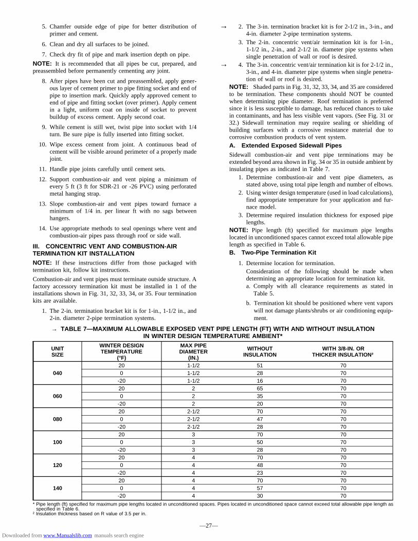
5. Chamfer outside edge of pipe for better distribution ofprimer and cement.
6. Clean and dry all surfaces to be joined.
7. Check dry fit of pipe and mark insertion depth on pipe.
NOTE: It is recommended that all pipes be cut, prepared, andpreassembled before permanently cementing any joint.
8. After pipes have been cut and preassembled, apply gener-ous layer of cement primer to pipe fitting socket and end ofpipe to insertion mark. Quickly apply approved cement toend of pipe and fitting socket (over primer). Apply cementin a light, uniform coat on inside of socket to preventbuildup of excess cement. Apply second coat.
9. While cement is still wet, twist pipe into socket with 1/4turn. Be sure pipe is fully inserted into fitting socket.
10. Wipe excess cement from joint. A continuous bead ofcement will be visible around perimeter of a properly madejoint.
11. Handle pipe joints carefully until cement sets.
12. Support combustion-air and vent piping a minimum ofevery 5 ft (3 ft for SDR-21 or -26 PVC) using perforatedmetal hanging strap.
13. Slope combustion-air and vent pipes toward furnace aminimum of 1/4 in. per linear ft with no sags betweenhangers.
14. Use appropriate methods to seal openings where vent andcombustion-air pipes pass through roof or side wall.
III. CONCENTRIC VENT AND COMBUSTION-AIRTERMINATION KIT INSTALLATION
NOTE: If these instructions differ from those packaged withtermination kit, follow kit instructions.
Combustion-air and vent pipes must terminate outside structure. Afactory accessory termination kit must be installed in 1 of theinstallations shown in Fig. 31, 32, 33, 34, or 35. Four terminationkits are available.
1. The 2-in. termination bracket kit is for 1-in., 1-1/2 in., and2-in. diameter 2-pipe termination systems.
2. The 3-in. termination bracket kit is for 2-1/2 in., 3-in., and4-in. diameter 2-pipe termination systems.
3. The 2-in. concentric vent/air termination kit is for 1-in.,1-1/2 in., 2-in., and 2-1/2 in. diameter pipe systems whensingle penetration of wall or roof is desired.
4. The 3-in. concentric vent/air termination kit is for 2-1/2 in.,3-in., and 4-in. diameter pipe systems when single penetra-tion of wall or roof is desired.
NOTE: Shaded parts in Fig. 31, 32, 33, 34, and 35 are consideredto be termination. These components should NOT be countedwhen determining pipe diameter. Roof termination is preferredsince it is less susceptible to damage, has reduced chances to takein contaminants, and has less visible vent vapors. (See Fig. 31 or32.) Sidewall termination may require sealing or shielding ofbuilding surfaces with a corrosive resistance material due tocorrosive combustion products of vent system.A. Extended Exposed Sidewall Pipes
Sidewall combustion-air and vent pipe terminations may beextended beyond area shown in Fig. 34 or 35 in outside ambient byinsulating pipes as indicated in Table 7.
1. Determine combustion-air and vent pipe diameters, asstated above, using total pipe length and number of elbows.
2. Using winter design temperature (used in load calculations),find appropriate temperature for your application and fur-nace model.
3. Determine required insulation thickness for exposed pipelengths.
NOTE: Pipe length (ft) specified for maximum pipe lengthslocated in unconditioned spaces cannot exceed total allowable pipelength as specified in Table 6.B. Two-Pipe Termination Kit
1. Determine location for termination.Consideration of the following should be made whendetermining an appropriate location for termination kit.a. Comply with all clearance requirements as stated in
Table 5.
b. Termination kit should be positioned where vent vaporswill not damage plants/shrubs or air conditioning equip-ment.
→ TABLE 7—MAXIMUM ALLOWABLE EXPOSED VENT PIPE LENGTH (FT) WITH AND WITHOUT INSULATIONIN WINTER DESIGN TEMPERATURE AMBIENT*
UNITSIZE
WINTER DESIGNTEMPERATURE
(°F)
MAX PIPEDIAMETER
(IN.)
WITHOUTINSULATION
WITH 3/8-IN. ORTHICKER INSULATION†
04020 1-1/2 51 700 1-1/2 28 70-20 1-1/2 16 70
06020 2 65 700 2 35 70-20 2 20 70
08020 2-1/2 70 700 2-1/2 47 70-20 2-1/2 28 70
10020 3 70 700 3 50 70-20 3 28 70
12020 4 70 700 4 48 70-20 4 23 70
14020 4 70 700 4 57 70-20 4 30 70
* Pipe length (ft) specified for maximum pipe lengths located in unconditioned spaces. Pipes located in unconditioned space cannot exceed total allowable pipe length asspecified in Table 6.
† Insulation thickness based on R value of 3.5 per in.
—27—
→
→
Downloaded from www.Manualslib.com manuals search engine

Fig. 34—Sidewall Termination of 12 in. or MoreA87225
MAINTAIN 12 IN. CLEARANCE ABOVE HIGHEST ANTICIPATED SNOW LEVEL OR GRADE, WHICHEVER IS GREATER.
90°
VENT
12 IN. SEPARATION BETWEEN BOTTOM OF COMBUSTION AIR AND BOTTOM OF VENT
BRACKET
COMBUSTION-AIR
12″ MINIMUM
OVERHANG OR ROOF
Fig. 32—Concentric Vent and Combustion-Air RoofTermination (Preferred)
A93054
COMBUSTION AIR
MAINTAIN 12 IN. (18 IN. FOR CANADA) MINIMUM CLEARANCE ABOVE HIGHEST ANTICIPATED SNOW LEVEL. MAXIMUM OF 24 IN. ABOVE ROOF.
VENT
Fig. 31—Roof Termination (Preferred)A87224
18″ MAXIMUM
COMBUSTION AIR
COUPLING
ROOF
VENT
BRACKET
VERTICAL SEPARATION BETWEEN COMBUSTION
AIR AND VENT8 3/4″ FOR 3″ KIT6 3/4″ FOR 2″ KIT
MAINTAIN 12 IN. MINIMUM CLEARANCE ABOVE HIGHEST
ANTICIPATED SNOW LEVEL. MAXIMUM OF 24 IN. ABOVE ROOF.
Fig. 35—Sidewall Termination of Less than 12 in.A87226
MAINTAIN 12 IN. CLEARANCE ABOVE HIGHEST ANTICIPATED SNOW LEVEL OR GRADE, WHICHEVER IS GREATER.
90°
VENT
12 IN. SEPARATION BETWEEN BOTTOM OF COMBUSTION AIR AND BOTTOM OF VENT
BRACKET
COUPLING
12″ MINIMUM
OVERHANG OR ROOF
COMBUSTION-AIR (ELBOW PARALLEL TO WALL)
Fig. 33—Concentric Vent and Combustion-Air SideTermination
A93055
MAINTAIN 12 IN. CLEARANCE ABOVE HIGHEST ANTICIPATED SNOW LEVEL OR GRADE, WHICHEVER IS GREATER.
COMBUSTION-AIR
VENT
1″ MAXIMUM
12″ MINIMUM
OVERHANG OR ROOF
—28—
Downloaded from www.Manualslib.com manuals search engine
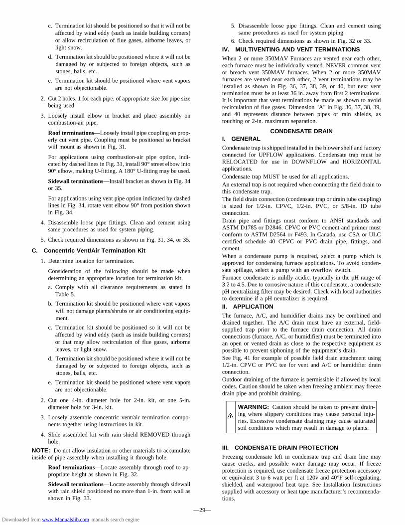
c. Termination kit should be positioned so that it will not beaffected by wind eddy (such as inside building corners)or allow recirculation of flue gases, airborne leaves, orlight snow.
d. Termination kit should be positioned where it will not bedamaged by or subjected to foreign objects, such asstones, balls, etc.
e. Termination kit should be positioned where vent vaporsare not objectionable.
2. Cut 2 holes, 1 for each pipe, of appropriate size for pipe sizebeing used.
3. Loosely install elbow in bracket and place assembly oncombustion-air pipe.
Roof terminations—Loosely install pipe coupling on prop-erly cut vent pipe. Coupling must be positioned so bracketwill mount as shown in Fig. 31.
For applications using combustion-air pipe option, indi-cated by dashed lines in Fig. 31, install 90° street elbow into90° elbow, making U-fitting. A 180° U-fitting may be used.
Sidewall terminations—Install bracket as shown in Fig. 34or 35.
For applications using vent pipe option indicated by dashedlines in Fig. 34, rotate vent elbow 90° from position shownin Fig. 34.
4. Disassemble loose pipe fittings. Clean and cement usingsame procedures as used for system piping.
5. Check required dimensions as shown in Fig. 31, 34, or 35.
C. Concentric Vent/Air Termination Kit
1. Determine location for termination.
Consideration of the following should be made whendetermining an appropriate location for termination kit.
a. Comply with all clearance requirements as stated inTable 5.
b. Termination kit should be positioned where vent vaporswill not damage plants/shrubs or air conditioning equip-ment.
c. Termination kit should be positioned so it will not beaffected by wind eddy (such as inside building corners)or that may allow recirculation of flue gases, airborneleaves, or light snow.
d. Termination kit should be positioned where it will not bedamaged by or subjected to foreign objects, such asstones, balls, etc.
e. Termination kit should be positioned where vent vaporsare not objectionable.
2. Cut one 4-in. diameter hole for 2-in. kit, or one 5-in.diameter hole for 3-in. kit.
3. Loosely assemble concentric vent/air termination compo-nents together using instructions in kit.
4. Slide assembled kit with rain shield REMOVED throughhole.
NOTE: Do not allow insulation or other materials to accumulateinside of pipe assembly when installing it through hole.
Roof terminations—Locate assembly through roof to ap-propriate height as shown in Fig. 32.
Sidewall terminations—Locate assembly through sidewallwith rain shield positioned no more than 1-in. from wall asshown in Fig. 33.
5. Disassemble loose pipe fittings. Clean and cement usingsame procedures as used for system piping.
6. Check required dimensions as shown in Fig. 32 or 33.
IV. MULTIVENTING AND VENT TERMINATIONS
When 2 or more 350MAV Furnaces are vented near each other,each furnace must be individually vented. NEVER common ventor breach vent 350MAV furnaces. When 2 or more 350MAVfurnaces are vented near each other, 2 vent terminations may beinstalled as shown in Fig. 36, 37, 38, 39, or 40, but next venttermination must be at least 36 in. away from first 2 terminations.It is important that vent terminations be made as shown to avoidrecirculation of flue gases. Dimension "A" in Fig. 36, 37, 38, 39,and 40 represents distance between pipes or rain shields, astouching or 2-in. maximum separation.
CONDENSATE DRAINI. GENERAL
Condensate trap is shipped installed in the blower shelf and factoryconnected for UPFLOW applications. Condensate trap must beRELOCATED for use in DOWNFLOW and HORIZONTALapplications.Condensate trap MUST be used for all applications.An external trap is not required when connecting the field drain tothis condensate trap.The field drain connection (condensate trap or drain tube coupling)is sized for 1/2-in. CPVC, 1/2-in. PVC, or 5/8-in. ID tubeconnection.Drain pipe and fittings must conform to ANSI standards andASTM D1785 or D2846. CPVC or PVC cement and primer mustconform to ASTM D2564 or F493. In Canada, use CSA or ULCcertified schedule 40 CPVC or PVC drain pipe, fittings, andcement.When a condensate pump is required, select a pump which isapproved for condensing furnace applications. To avoid conden-sate spillage, select a pump with an overflow switch.Furnace condensate is mildly acidic, typically in the pH range of3.2 to 4.5. Due to corrosive nature of this condensate, a condensatepH neutralizing filter may be desired. Check with local authoritiesto determine if a pH neutralizer is required.II. APPLICATION
The furnace, A/C, and humidifier drains may be combined anddrained together. The A/C drain must have an external, field-supplied trap prior to the furnace drain connection. All drainconnections (furnace, A/C, or humidifier) must be terminated intoan open or vented drain as close to the respective equipment aspossible to prevent siphoning of the equipment’s drain.See Fig. 41 for example of possible field drain attachment using1/2-in. CPVC or PVC tee for vent and A/C or humidifier drainconnection.Outdoor draining of the furnace is permissible if allowed by localcodes. Caution should be taken when freezing ambient may freezedrain pipe and prohibit draining.
WARNING: Caution should be taken to prevent drain-ing where slippery conditions may cause personal inju-ries. Excessive condensate draining may cause saturatedsoil conditions which may result in damage to plants.
III. CONDENSATE DRAIN PROTECTION
Freezing condensate left in condensate trap and drain line maycause cracks, and possible water damage may occur. If freezeprotection is required, use condensate freeze protection accessoryor equivalent 3 to 6 watt per ft at 120v and 40°F self-regulating,shielded, and waterproof heat tape. See Installation Instructionssupplied with accessory or heat tape manufacturer’s recommenda-tions.
—29—
Downloaded from www.Manualslib.com manuals search engine

Fig. 39—Sidewall Termination of 12 in. or Less(Dimension "A" is Touching or 2-In. Maximum Separation)
A96129
A
COMBUSTION AIR
COMBUSTION AIR
VENT
Fig. 37—Concentric Vent and Combustion-AirRoof Termination
(Dimension "A" is Touching or 2-In. Maximum Separation)
A93056
COMBUSTION AIR
VENTVENT
A
Fig. 36—Rooftop Termination (Dimension "A" is Touching or 2-In. Maximum Separation)A96128
A
Fig. 40—Sidewall Termination of More Than 12 in.(Dimension "A" is Touching or 2-In. Maximum Separation)
A96130
VENT
A
COMBUSTION AIRCOMBUSTION AIR
Fig. 38—Concentric Vent and Combustion-AirSide Termination
(Dimension "A" is Touching or 2-In. Maximum Separation)
A93057
COMBUSTION AIR
VENT
A
VENT
1″ MAXIMUM (TYP)
—30—
Downloaded from www.Manualslib.com manuals search engine

1. Fold heat tape in half and wrap on itself 3 times.
2. Locate heat tape between sides of condensate trap back.(See Fig. 42.)
3. Use wire ties to secure heat tape in place. Wire ties can bepositioned in notches of condensate trap sides. (See Fig.42.)
4. Wrap field drain pipe with remaining heat tape, approxi-mately 1 wrap per ft.
5. When using field-supplied heat tape, follow heat tapemanufacturer’s instructions for all other installation guide-lines.
SEQUENCE OF OPERATION
CAUTION: Furnace control must be grounded forproper operation, or control will lock out. Control isgrounded through green wire routed to gas valve andburner box screw.
Using schematic diagram, follow sequence of operation throughdifferent modes. (See Fig. 24.) Read and follow wiring diagramcarefully.NOTE: If 115-v power supply to furnace or blower access panelswitch is interrupted during a call for heat, blower operates for 90sec when power is restored before heating cycle is resumed.I. HEATING MODE
When wall thermostat calls for heat, R-W circuit closes. Furnacecontrol performs a self-check, verifies pressure switch contacts areopen, and starts inducer motor.
1. Prepurge period—As inducer motor comes up to speed,pressure switch contacts close to begin a 15-sec prepurgeperiod.
2. Ignitor warm up—At end of prepurge period, ignitor isenergized for a 17-sec ignitor warm-up period.
3. Ignition sequence—When ignitor warm-up period is com-pleted, gas valve opens, permitting gas flow to burnerswhere it is ignited. After 5 sec, ignitor is de-energized anda 2-sec flame-sensing period begins.HUM terminal on control center is energized with gasvalve. See Accessories — Humidifier section.
4. Flame sensing—When burner flame is sensed, controlbegins blower on delay period and continues holding gasvalve open.If burner flame is not sensed, control center de-energizesgas valve and ignition sequence is repeated.
NOTE: Ignition sequence repeats 3 additional times before alockout occurs. Lockout automatically resets after 3 hr or can bemanually reset by turning off 115v (not at thermostat) for 3 secminimum, then turning it on again.
5. Blower on delay—Sixty sec after burner flame is proven(40 sec if jumper has been cut for 140 size unit in downfloworientation), blower motor is energized on heating speed.Simultaneously, electronic air cleaner terminal EAC-1 isenergized.
Fig. 41—Example of Field Drain AttachmentA94054
OPEN STAND PIPE FOR
A/C OR HUMIDIFIER
DRAIN
TEE
TO OPEN DRAIN
CAUTION: Unit must not be installed, operated, andthen turned off and left in an unoccupied structure duringcold weather when temperature drops to 32°F and belowunless drain trap and drain line have adequate freezeprotection. See Service and Maintenance Instructions forwinterizing procedure.
A93058
32°F MINIMUM INSTALLED AMBIENT OR FREEZE PROTECTION REQUIRED
Fig. 42—Condensate Trap Heat TapeA93036
CONDENSATE TRAP
WIRE TIE(S)
HEAT TAPE (3 WRAPS MINIMUM)
—31—
→
Downloaded from www.Manualslib.com manuals search engine

6. Blower off delay—When thermostat is satisfied, circuitbetween R-W is opened, de-energizing gas valve (stoppinggas flow to burners) and humidifier. Blower motor andelectronic air cleaner remains energized 90, 135, 180, or225 sec (depending on blower off time selection). Furnaceis factory shipped set for a 135-sec blower off delay.
7. Post purge—Inducer motor remains energized 15 sec afterburners are extinguished (5 sec if jumper has been cut for140 size unit in downflow orientation).
II. COOLING MODE
When thermostat calls for cooling, R-G and R-Y circuits close.R-Y circuit starts outdoor condensing unit, and combined R-Y andR-G circuit starts furnace blower motor on cooling speed. Elec-tronic air cleaner EAC-1 terminal is energized with 115v wheneverblower is operating.When thermostat is satisfied, R-G and R-Y circuits are opened,furnace blower continues operating on cooling speed for anadditional 90 sec.
III. CONTINUOUS BLOWER MODE
When R-G circuit is made, blower motor operates on heatingspeed.NOTE: Electronic air cleaner EAC-1 terminal is energized with115v whenever blower is operating.If a call for heat (R-W) occurs while thermostat is in continuousblower mode, blower stops to allow furnace heat exchangers toheat up more quickly, then restarts at end of blower on delayperiod of 60 sec (40 sec if jumper has been cut for 140 size unit indownflow orientation).Blower reverts to continuous operation after heating cycle iscompleted.If a call for cooling (R-Y) occurs while thermostat is in continuousblower mode, blower changes from continuous blower speed(heating speed) to cooling speed.When thermostat cooling call is satisfied, R-Y opens and bloweroperates an additional 90 sec at cooling speed before revertingback to continuous operation (heating speed).IV. HEAT PUMP MODE
When installed with a heat pump, furnace control automaticallychanges blower on delay timing sequence to avoid no bloweroperation time during demand defrost cycles. When R-W and R-Yor R-W, R-Y, and R-G thermostat inputs are received at the sametime at furnace control center, control starts blower in heatingspeed. Then a gas heat mode begins. Blower remains operating atheating speed for 15 sec or until end of prepurge period, thenblower shuts off until end of ignitor warm up and trial for ignitionperiods (a total of 24 sec). Blower restarts at heating speed.When R-W thermostat call disappears, control completes inducerpost-purge period of 15 sec (5 sec if jumper has been cut for 140size unit in downflow orientation) and changes to cooling speedafter a 2-sec delay.If R-W, R-Y, and R-G thermostat signals should disappearsimultaneously, blower remains on for selected heating blower offdelay period (90, 135, 180, or 225 sec), and the inducer goesthrough 15 sec post-purge period (5 sec if jumper has been cut for140 size unit in downflow orientation). If R-W and R-Y thermostatsignals should disappear, leaving R-G thermostat signal, blowerremains on in heating speed and inducer remains on for 15 sec (5sec if jumper has been cut for 140 size unit in downfloworientation) to complete post-purge period.Control initiates a 90-sec blower only on period before startinganother heat pump cycle if there is a power interruption. Anytimecontrol senses false flame, control locks out of heating mode. Thisreaction occurs because control ignores W input due to false flamesignal and, as a result, sees only Y input and goes into coolingmode blower off delay. All other control functions remain instandard format.
NOTE: EAC-1 terminal is energized whenever blower operates.HUM terminal is only energized when gas valve is energized.
V. COMPONENT TEST
A. Component Test Sequence
NOTE: All components are functionally operated except the gasvalve.
When component test is initiated, the following sequence of eventsoccurs:
1. LED flashes a status code 4 times.
2. Inducer motor starts and continues to run for remainder ofcomponent test.
3. Hot surface ignitor is energized for 15 sec, then de-energized.
4. Main blower operates at cooling speed for 10 sec, then turnsoff.
5. Main blower operates at heating speed for 10 sec, then turnsoff.
6. Inducer motor stops.
Component test can be initiated by one of the following proce-dures.
B. Initiating Component Test By Removing Main LimitSwitch Wire
NOTE: NO thermostat signal may be present at control centerand all blower time delay off periods must be completed.
1. Leave 115-v power to furnace turned on.
2. Remove main furnace door.
3. Look into blower access panel sight glass for current LEDstatus.
NOTE: Leave blower access panel installed to maintain power tocontrol center to view current LED status.
4. BRIEFLY remove either wire from the main limit switchuntil the LED goes out, then reconnect it.
CAUTION: Make sure limit switch wire does not con-tact any metallic component such as the gas valve. If wireis shorted, 3-amp fuse on control center will blow.
NOTE: If wire to main limit is disconnected longer than 4 sec, thecontrol senses limit circuit is open. Main blower will start andstatus retrieval request will be ignored.
5. When above items have been completed, the componenttest sequence will occur as described in the Component TestSequence section above.
NOTE: Be sure to record the status code which is flashed 4 timesat start of component test for further troubleshooting.
6. After component test is completed and LED is ON continu-ously indicating the furnace is ready to operate when asignal from the thermostat is received, replace main furnacedoor.
C. Initiating Component Test By Jumpering ControlTEST Terminal
1. Remove main furnace door.
2. Remove blower access panel.
3. Manually close blower access panel door switch. Use apiece of tape to hold switch closed.
—32—
→
→
→
→
Downloaded from www.Manualslib.com manuals search engine
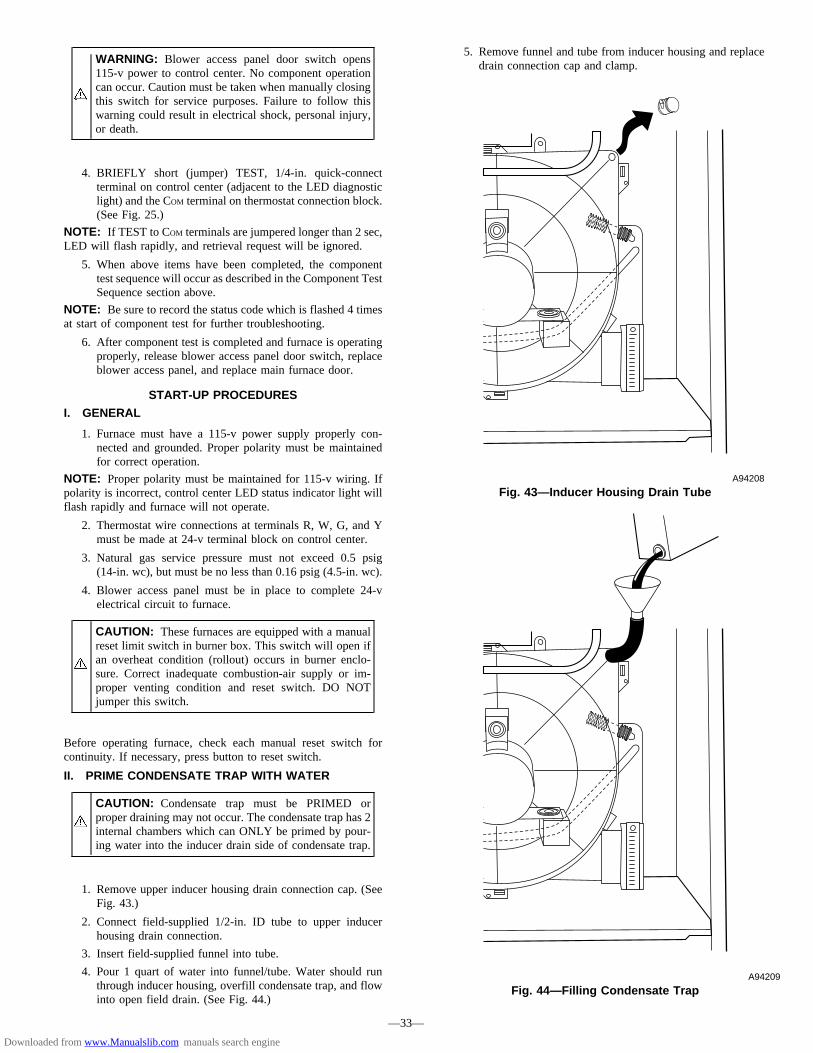
WARNING: Blower access panel door switch opens115-v power to control center. No component operationcan occur. Caution must be taken when manually closingthis switch for service purposes. Failure to follow thiswarning could result in electrical shock, personal injury,or death.
4. BRIEFLY short (jumper) TEST, 1/4-in. quick-connectterminal on control center (adjacent to the LED diagnosticlight) and the COM terminal on thermostat connection block.(See Fig. 25.)
NOTE: If TEST to COM terminals are jumpered longer than 2 sec,LED will flash rapidly, and retrieval request will be ignored.
5. When above items have been completed, the componenttest sequence will occur as described in the Component TestSequence section above.
NOTE: Be sure to record the status code which is flashed 4 timesat start of component test for further troubleshooting.
6. After component test is completed and furnace is operatingproperly, release blower access panel door switch, replaceblower access panel, and replace main furnace door.
START-UP PROCEDURES
I. GENERAL
1. Furnace must have a 115-v power supply properly con-nected and grounded. Proper polarity must be maintainedfor correct operation.
NOTE: Proper polarity must be maintained for 115-v wiring. Ifpolarity is incorrect, control center LED status indicator light willflash rapidly and furnace will not operate.
2. Thermostat wire connections at terminals R, W, G, and Ymust be made at 24-v terminal block on control center.
3. Natural gas service pressure must not exceed 0.5 psig(14-in. wc), but must be no less than 0.16 psig (4.5-in. wc).
4. Blower access panel must be in place to complete 24-velectrical circuit to furnace.
CAUTION: These furnaces are equipped with a manualreset limit switch in burner box. This switch will open ifan overheat condition (rollout) occurs in burner enclo-sure. Correct inadequate combustion-air supply or im-proper venting condition and reset switch. DO NOTjumper this switch.
Before operating furnace, check each manual reset switch forcontinuity. If necessary, press button to reset switch.
II. PRIME CONDENSATE TRAP WITH WATER
CAUTION: Condensate trap must be PRIMED orproper draining may not occur. The condensate trap has 2internal chambers which can ONLY be primed by pour-ing water into the inducer drain side of condensate trap.
1. Remove upper inducer housing drain connection cap. (SeeFig. 43.)
2. Connect field-supplied 1/2-in. ID tube to upper inducerhousing drain connection.
3. Insert field-supplied funnel into tube.
4. Pour 1 quart of water into funnel/tube. Water should runthrough inducer housing, overfill condensate trap, and flowinto open field drain. (See Fig. 44.)
5. Remove funnel and tube from inducer housing and replacedrain connection cap and clamp.
Fig. 44—Filling Condensate TrapA94209
Fig. 43—Inducer Housing Drain TubeA94208
—33—
Downloaded from www.Manualslib.com manuals search engine

III. PURGE GAS LINES
If not previously done, purge lines after all connections have beenmade and check for leaks.
WARNING: Never purge a gas line into a combustionchamber. Never use matches, candles, flame, or othersources of ignition for purpose of checking leakage. Usea soap-and-water solution to check for leakage. Failure tofollow this warning could result in fire, explosion, per-sonal injury, or death.
IV. ADJUSTMENTS
A. Set Gas Input Rate
Furnace gas input rate on rating plate is for installations at altitudesup to 2000 ft.
In the U.S.A., the input ratings for altitudes above 2000 ft must bereduced by 2 percent for each 1000 ft above sea level.
In Canada, the input ratings must be derated by 5 percent foraltitudes of 2000 ft to 4500 ft above sea level.
Furnace input rate must be within±2 percent of input on furnacerating plate adjusted for altitude.
1. Determine natural gas orifice size and manifold pressure forcorrect input.
a. Obtain average yearly heat value (at installed altitude)from local gas supplier.
b. Obtain average yearly specific gravity from local gassupplier.
c. Verify furnace model and size. Table 8 can only be usedfor model 350MAV furnaces with heating sizes of 040through 120. Table 9 can only be used for model350MAV furnaces with a 140 heating size.
d. Find installation altitude in Table 8 or 9.
NOTE: For Canada altitudes of 2000 to 4500 ft, use U.S.A.altitudes of 2001 to 3000 ft in Table 8 or 9.
e. Find closest natural gas heat value and specific gravityon Table 8 or 9.
f. Follow heat value and specific gravity lines to point ofintersection to find orifice size and manifold pressuresettings for proper operation.
EXAMPLE: (0—2000 ft altitude using Table 8)Heating value = 1050 Btu/cu ftSpecific gravity = 0.62Therefore: Orifice No. 45
Manifold pressure 3.6-in. wc* Furnace is shipped with No. 45 orifices. In this exampleall main burner orifices are the correct size and do not needto be changed to obtain the proper input rate.
Check and verify burner orifice size in furnace. NEVER ASSUMEORIFICE SIZE; ALWAYS CHECK AND VERIFY.
2. Adjust manifold pressure to obtain input rate.NOTE: Manifold pressure must always be measured with burnerenclosure front REMOVED. Gas meter must always be clockedwith burner enclosure front INSTALLED.
a. Remove burner enclosure front.
b. Remove cap that conceals adjustment screw for gasvalve regulator. (See Fig. 45.)
c. Turn adjusting screw, counterclockwise (out) to decreasemanifold pressure or clockwise (in) to increase manifoldpressure.
NOTE: This furnace has been approved for a manifold pressureof 3.2 in. wc to 3.8 in. wc when installed at altitudes up to 2000 ft.For altitudes above 2000 ft, the manifold pressure can be adjustedfrom 2.0 in. wc to 3.8 in. wc.
CAUTION: DO NOT bottom out gas valve regulatoradjusting screw. This can result in unregulated manifoldpressure and result in excess overfire and heat exchangerfailures.
NOTE: If orifice hole appears damaged or it is suspected to havebeen redrilled, check orifice hole with a numbered drill bit ofcorrect size. Never redrill an orifice. A burr-free and squarelyaligned orifice hole is essential for proper flame characteristics.
d. Replace gas valve regulator adjustment screw cap.
e. Replace burner enclosure front and verify adjusted gasinput rate using method outlined in item 3.
Fig. 45—Redundant Automatic Gas ValveA95622
MANIFOLD PRESSURE TAP
GAS PRESSURE REGULATOR ADJUSTMENT
BURNER ENCLOSURE REFERENCE PRESSURE TAP
INLET PRESSURE TAP
ON AND OFF SWITCH
CAUTION: DO NOT redrill orifices. Improper drilling(burrs, out-of-round holes, etc.) can cause excessiveburner noise and misdirection of burner flames. This canresult in flame impingement of burners and heat exchang-ers causing failures.
A93059
BURNER ORIFICE
—34—
→
→
→
→
→→
→
Downloaded from www.Manualslib.com manuals search engine

→ TABLE 8—MODEL 350MAV ORIFICE SIZE AND MANIFOLD PRESSURE FOR CORRECT INPUTFOR USE WITH 040 THROUGH 120 SIZE FURNACES ONLY
(TABULATED DATA BASED ON 20,000 BTUH PER BURNER, DERATED 2% FOR EACH 1000 FT ABOVE SEA LEVEL)
ALTITUDERANGE(FT)
AVG GASHEAT VALUEAT ALTITUDE(BTU/CU FT)
SPECIFIC GRAVITY OF NATURAL GAS0.58 0.60 0.62 0.64 0.66
OrificeNo.
ManifoldPressure
OrificeNo.
ManifoldPressure
OrificeNo.
ManifoldPressure
OrificeNo.
ManifoldPressure
OrificeNo.
ManifoldPressure
U.S.A.andCanada
850 43 3.7 43 3.8 42 3.2 42 3.3 42 3.4875 43 3.5 43 3.6 43 3.7 43 3.8 42 3.2900 44 3.7 43 3.4 43 3.5 43 3.6 43 3.7
0 925 44 3.5 44 3.7 44 3.8 43 3.4 43 3.5950 44 3.4 44 3.5 44 3.6 44 3.7 44 3.8
to 975 44 3.2 44 3.3 44 3.4 44 3.5 44 3.61000 45 3.7 45 3.8 44 3.2 44 3.4 44 3.5
2000 1025 45 3.5 45 3.6 45 3.7 44 3.2 44 3.31050 45 3.3 45 3.4 45 3.6 45 3.7 45 3.81075 45 3.2 45 3.3 45 3.4 45 3.5 45 3.61100 47 3.6 47 3.7 45 3.2 45 3.4 45 3.5
ALTITUDERANGE(FT)
AVG GASHEAT VALUEAT ALTITUDE(BTU/CU FT)
SPECIFIC GRAVITY OF NATURAL GAS0.58 0.60 0.62 0.64 0.66
OrificeNo.
ManifoldPressure
OrificeNo.
ManifoldPressure
OrificeNo.
ManifoldPressure
OrificeNo.
ManifoldPressure
OrificeNo.
ManifoldPressure
U.S.A.andCanada
U.S.A. 775 43 3.8 42 3.2 42 3.3 42 3.4 42 3.5Altitudes 800 43 3.5 43 3.7 43 3.8 42 3.2 42 3.32001 825 44 3.8 43 3.4 43 3.6 43 3.7 43 3.8to 850 44 3.6 44 3.7 44 3.8 43 3.5 43 3.6
3000 875 44 3.4 44 3.5 44 3.6 44 3.7 43 3.4or 900 44 3.2 44 3.3 44 3.4 44 3.5 44 3.6
Canada 925 45 3.7 45 3.8 44 3.2 44 3.3 44 3.4Altitudes 950 45 3.5 45 3.6 45 3.7 45 3.8 44 3.32000 975 45 3.3 45 3.4 45 3.5 45 3.6 45 3.8to 1000 45 3.1 45 3.2 45 3.4 45 3.5 45 3.6
4500 1025 45 3.0 45 3.1 45 3.2 45 3.3 45 3.4
ALTITUDERANGE(FT)
AVG GASHEAT VALUEAT ALTITUDE(BTU/CU FT)
SPECIFIC GRAVITY OF NATURAL GAS0.58 0.60 0.62 0.64 0.66
OrificeNo.
ManifoldPressure
OrificeNo.
ManifoldPressure
OrificeNo.
ManifoldPressure
OrificeNo.
ManifoldPressure
OrificeNo.
ManifoldPressure
U.S.A.Only
750 43 3.7 43 3.8 42 3.3 42 3.4 42 3.5775 43 3.5 43 3.6 43 3.7 43 3.8 42 3.2800 44 3.7 43 3.4 43 3.5 43 3.6 43 3.7
3001 825 44 3.5 44 3.6 44 3.8 43 3.4 43 3.5850 44 3.3 44 3.4 44 3.5 44 3.7 44 3.8
to 875 45 3.8 44 3.2 44 3.3 44 3.5 44 3.6900 45 3.6 45 3.7 45 3.8 44 3.3 44 3.4
4000 925 45 3.4 45 3.5 45 3.6 45 3.7 44 3.2950 45 3.2 45 3.3 45 3.4 45 3.5 45 3.7975 45 3.0 45 3.2 45 3.3 45 3.4 45 3.51000 45 2.9 45 3.0 45 3.1 45 3.2 45 3.3
—35—
Downloaded from www.Manualslib.com manuals search engine
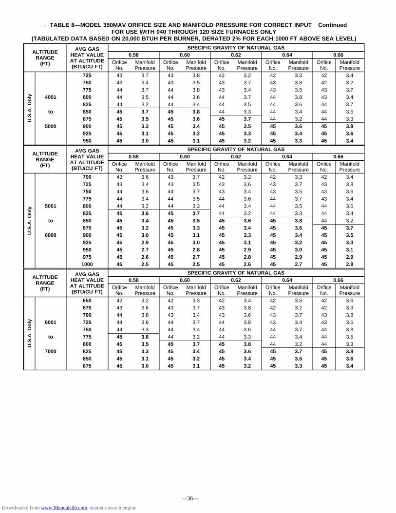
→ TABLE 8—MODEL 350MAV ORIFICE SIZE AND MANIFOLD PRESSURE FOR CORRECT INPUT ContinuedFOR USE WITH 040 THROUGH 120 SIZE FURNACES ONLY
(TABULATED DATA BASED ON 20,000 BTUH PER BURNER, DERATED 2% FOR EACH 1000 FT ABOVE SEA LEVEL)
ALTITUDERANGE(FT)
AVG GASHEAT VALUEAT ALTITUDE(BTU/CU FT)
SPECIFIC GRAVITY OF NATURAL GAS0.58 0.60 0.62 0.64 0.66
OrificeNo.
ManifoldPressure
OrificeNo.
ManifoldPressure
OrificeNo.
ManifoldPressure
OrificeNo.
ManifoldPressure
OrificeNo.
ManifoldPressure
U.S.A.Only
725 43 3.7 43 3.8 42 3.2 42 3.3 42 3.4750 43 3.4 43 3.5 43 3.7 43 3.8 42 3.2775 44 3.7 44 3.8 43 3.4 43 3.5 43 3.7
4001 800 44 3.5 44 3.6 44 3.7 44 3.8 43 3.4825 44 3.2 44 3.4 44 3.5 44 3.6 44 3.7
to 850 45 3.7 45 3.8 44 3.3 44 3.4 44 3.5875 45 3.5 45 3.6 45 3.7 44 3.2 44 3.3
5000 900 45 3.3 45 3.4 45 3.5 45 3.6 45 3.8925 45 3.1 45 3.2 45 3.3 45 3.4 45 3.6950 45 3.0 45 3.1 45 3.2 45 3.3 45 3.4
ALTITUDERANGE(FT)
AVG GASHEAT VALUEAT ALTITUDE(BTU/CU FT)
SPECIFIC GRAVITY OF NATURAL GAS0.58 0.60 0.62 0.64 0.66
OrificeNo.
ManifoldPressure
OrificeNo.
ManifoldPressure
OrificeNo.
ManifoldPressure
OrificeNo.
ManifoldPressure
OrificeNo.
ManifoldPressure
U.S.A.Only
700 43 3.6 43 3.7 42 3.2 42 3.3 42 3.4725 43 3.4 43 3.5 43 3.6 43 3.7 43 3.8750 44 3.6 44 3.7 43 3.4 43 3.5 43 3.6775 44 3.4 44 3.5 44 3.6 44 3.7 43 3.4
5001 800 44 3.2 44 3.3 44 3.4 44 3.5 44 3.6825 45 3.6 45 3.7 44 3.2 44 3.3 44 3.4
to 850 45 3.4 45 3.5 45 3.6 45 3.8 44 3.2875 45 3.2 45 3.3 45 3.4 45 3.6 45 3.7
6000 900 45 3.0 45 3.1 45 3.3 45 3.4 45 3.5925 45 2.9 45 3.0 45 3.1 45 3.2 45 3.3950 45 2.7 45 2.8 45 2.9 45 3.0 45 3.1975 45 2.6 45 2.7 45 2.8 45 2.9 45 2.91000 45 2.5 45 2.5 45 2.6 45 2.7 45 2.8
ALTITUDERANGE(FT)
AVG GASHEAT VALUEAT ALTITUDE(BTU/CU FT)
SPECIFIC GRAVITY OF NATURAL GAS0.58 0.60 0.62 0.64 0.66
OrificeNo.
ManifoldPressure
OrificeNo.
ManifoldPressure
OrificeNo.
ManifoldPressure
OrificeNo.
ManifoldPressure
OrificeNo.
ManifoldPressure
U.S.A.Only
650 42 3.2 42 3.3 42 3.4 42 3.5 42 3.6675 43 3.6 43 3.7 43 3.8 42 3.2 42 3.3700 44 3.8 43 3.4 43 3.6 43 3.7 43 3.8
6001 725 44 3.6 44 3.7 44 3.8 43 3.4 43 3.5750 44 3.3 44 3.4 44 3.6 44 3.7 44 3.8
to 775 45 3.8 44 3.2 44 3.3 44 3.4 44 3.5800 45 3.5 45 3.7 45 3.8 44 3.2 44 3.3
7000 825 45 3.3 45 3.4 45 3.6 45 3.7 45 3.8850 45 3.1 45 3.2 45 3.4 45 3.5 45 3.6875 45 3.0 45 3.1 45 3.2 45 3.3 45 3.4
—36—
Downloaded from www.Manualslib.com manuals search engine

→ TABLE 8—MODEL 350MAV ORIFICE SIZE AND MANIFOLD PRESSURE FOR CORRECT INPUT ContinuedFOR USE WITH 040 THROUGH 120 SIZE FURNACES ONLY
(TABULATED DATA BASED ON 20,000 BTUH PER BURNER, DERATED 2% FOR EACH 1000 FT ABOVE SEA LEVEL)
ALTITUDERANGE(FT)
AVG GASHEAT VALUEAT ALTITUDE(BTU/CU FT)
SPECIFIC GRAVITY OF NATURAL GAS0.58 0.60 0.62 0.64 0.66
OrificeNo.
ManifoldPressure
OrificeNo.
ManifoldPressure
OrificeNo.
ManifoldPressure
OrificeNo.
ManifoldPressure
OrificeNo.
ManifoldPressure
U.S.A.Only
625 43 3.8 42 3.3 42 3.4 42 3.5 42 3.6650 43 3.5 43 3.7 43 3.8 42 3.2 42 3.3675 44 3.8 43 3.4 43 3.5 43 3.6 43 3.7
7001 700 44 3.5 44 3.6 44 3.8 43 3.4 43 3.5725 44 3.3 44 3.4 44 3.5 44 3.6 44 3.7
to 750 45 3.7 45 3.8 44 3.3 44 3.4 44 3.5775 45 3.5 45 3.6 45 3.7 45 3.8 44 3.3
8000 800 45 3.3 45 3.4 45 3.5 45 3.6 45 3.7825 45 3.1 45 3.2 45 3.3 45 3.4 45 3.5850 45 2.9 45 3.0 45 3.1 45 3.2 45 3.3
ALTITUDERANGE(FT)
AVG GASHEAT VALUEAT ALTITUDE(BTU/CU FT)
SPECIFIC GRAVITY OF NATURAL GAS0.58 0.60 0.62 0.64 0.66
OrificeNo.
ManifoldPressure
OrificeNo.
ManifoldPressure
OrificeNo.
ManifoldPressure
OrificeNo.
ManifoldPressure
OrificeNo.
ManifoldPressure
U.S.A.Only
600 43 3.8 42 3.3 42 3.4 42 3.5 42 3.6625 43 3.5 43 3.6 43 3.8 42 3.2 42 3.3
8001 650 44 3.7 43 3.4 43 3.5 43 3.6 43 3.7675 44 3.5 44 3.6 44 3.7 44 3.8 43 3.4
to 700 44 3.2 44 3.3 44 3.4 44 3.6 44 3.7725 45 3.6 45 3.8 44 3.2 44 3.3 44 3.4
9000 750 45 3.4 45 3.5 45 3.6 45 3.8 44 3.2775 45 3.2 45 3.3 45 3.4 45 3.5 45 3.6800 45 3.0 45 3.1 45 3.2 45 3.3 45 3.4
ALTITUDERANGE(FT)
AVG GASHEAT VALUEAT ALTITUDE(BTU/CU FT)
SPECIFIC GRAVITY OF NATURAL GAS0.58 0.60 0.62 0.64 0.66
OrificeNo.
ManifoldPressure
OrificeNo.
ManifoldPressure
OrificeNo.
ManifoldPressure
OrificeNo.
ManifoldPressure
OrificeNo.
ManifoldPressure
U.S.A.Only
575 43 3.8 42 3.2 42 3.3 42 3.5 42 3.6600 43 3.5 43 3.6 43 3.7 42 3.2 42 3.3
9001 625 44 3.7 44 3.8 43 3.5 43 3.6 43 3.7650 44 3.4 44 3.5 44 3.7 44 3.8 43 3.4
to 675 45 3.8 44 3.3 44 3.4 44 3.5 44 3.6700 45 3.6 45 3.7 45 3.8 44 3.3 44 3.4
10,000 725 45 3.3 45 3.4 45 3.6 45 3.7 45 3.8750 45 3.1 45 3.2 45 3.3 45 3.4 45 3.5775 45 2.9 45 3.0 45 3.1 45 3.2 45 3.3
—37—
Downloaded from www.Manualslib.com manuals search engine
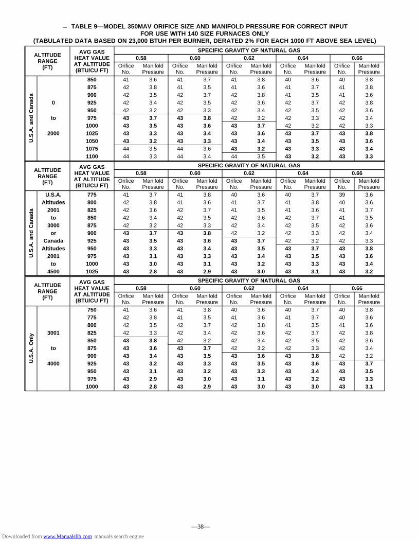
→ TABLE 9—MODEL 350MAV ORIFICE SIZE AND MANIFOLD PRESSURE FOR CORRECT INPUTFOR USE WITH 140 SIZE FURNACES ONLY
(TABULATED DATA BASED ON 23,000 BTUH PER BURNER, DERATED 2% FOR EACH 1000 FT ABOVE SEA LEVEL)
ALTITUDERANGE(FT)
AVG GASHEAT VALUEAT ALTITUDE(BTU/CU FT)
SPECIFIC GRAVITY OF NATURAL GAS0.58 0.60 0.62 0.64 0.66
OrificeNo.
ManifoldPressure
OrificeNo.
ManifoldPressure
OrificeNo.
ManifoldPressure
OrificeNo.
ManifoldPressure
OrificeNo.
ManifoldPressure
U.S.A.andCanada
850 41 3.6 41 3.7 41 3.8 40 3.6 40 3.8875 42 3.8 41 3.5 41 3.6 41 3.7 41 3.8900 42 3.5 42 3.7 42 3.8 41 3.5 41 3.6
0 925 42 3.4 42 3.5 42 3.6 42 3.7 42 3.8950 42 3.2 42 3.3 42 3.4 42 3.5 42 3.6
to 975 43 3.7 43 3.8 42 3.2 42 3.3 42 3.41000 43 3.5 43 3.6 43 3.7 42 3.2 42 3.3
2000 1025 43 3.3 43 3.4 43 3.6 43 3.7 43 3.81050 43 3.2 43 3.3 43 3.4 43 3.5 43 3.61075 44 3.5 44 3.6 43 3.2 43 3.3 43 3.41100 44 3.3 44 3.4 44 3.5 43 3.2 43 3.3
ALTITUDERANGE(FT)
AVG GASHEAT VALUEAT ALTITUDE(BTU/CU FT)
SPECIFIC GRAVITY OF NATURAL GAS0.58 0.60 0.62 0.64 0.66
OrificeNo.
ManifoldPressure
OrificeNo.
ManifoldPressure
OrificeNo.
ManifoldPressure
OrificeNo.
ManifoldPressure
OrificeNo.
ManifoldPressure
U.S.A.andCanada
U.S.A. 775 41 3.7 41 3.8 40 3.6 40 3.7 39 3.6Altitudes 800 42 3.8 41 3.6 41 3.7 41 3.8 40 3.62001 825 42 3.6 42 3.7 41 3.5 41 3.6 41 3.7to 850 42 3.4 42 3.5 42 3.6 42 3.7 41 3.5
3000 875 42 3.2 42 3.3 42 3.4 42 3.5 42 3.6or 900 43 3.7 43 3.8 42 3.2 42 3.3 42 3.4
Canada 925 43 3.5 43 3.6 43 3.7 42 3.2 42 3.3Altitudes 950 43 3.3 43 3.4 43 3.5 43 3.7 43 3.82001 975 43 3.1 43 3.3 43 3.4 43 3.5 43 3.6to 1000 43 3.0 43 3.1 43 3.2 43 3.3 43 3.4
4500 1025 43 2.8 43 2.9 43 3.0 43 3.1 43 3.2
ALTITUDERANGE(FT)
AVG GASHEAT VALUEAT ALTITUDE(BTU/CU FT)
SPECIFIC GRAVITY OF NATURAL GAS0.58 0.60 0.62 0.64 0.66
OrificeNo.
ManifoldPressure
OrificeNo.
ManifoldPressure
OrificeNo.
ManifoldPressure
OrificeNo.
ManifoldPressure
OrificeNo.
ManifoldPressure
U.S.A.Only
750 41 3.6 41 3.8 40 3.6 40 3.7 40 3.8775 42 3.8 41 3.5 41 3.6 41 3.7 40 3.6800 42 3.5 42 3.7 42 3.8 41 3.5 41 3.6
3001 825 42 3.3 42 3.4 42 3.6 42 3.7 42 3.8850 43 3.8 42 3.2 42 3.4 42 3.5 42 3.6
to 875 43 3.6 43 3.7 42 3.2 42 3.3 42 3.4900 43 3.4 43 3.5 43 3.6 43 3.8 42 3.2
4000 925 43 3.2 43 3.3 43 3.5 43 3.6 43 3.7950 43 3.1 43 3.2 43 3.3 43 3.4 43 3.5975 43 2.9 43 3.0 43 3.1 43 3.2 43 3.31000 43 2.8 43 2.9 43 3.0 43 3.0 43 3.1
—38—
Downloaded from www.Manualslib.com manuals search engine

→ TABLE 9—MODEL 350MAV ORIFICE SIZE AND MANIFOLD PRESSURE FOR CORRECT INPUT ContinuedFOR USE WITH 140 SIZE FURNACES ONLY
(TABULATED DATA BASED ON 23,000 BTUH PER BURNER, DERATED 2% FOR EACH 1000 FT ABOVE SEA LEVEL)
ALTITUDERANGE(FT)
AVG GASHEAT VALUEAT ALTITUDE(BTU/CU FT)
SPECIFIC GRAVITY OF NATURAL GAS0.58 0.60 0.62 0.64 0.66
OrificeNo.
ManifoldPressure
OrificeNo.
ManifoldPressure
OrificeNo.
ManifoldPressure
OrificeNo.
ManifoldPressure
OrificeNo.
ManifoldPressure
U.S.A.Only
725 41 3.6 41 3.7 41 3.8 40 3.6 40 3.8750 42 3.7 42 3.8 41 3.6 41 3.7 41 3.8
4001 775 42 3.5 42 3.6 42 3.7 42 3.8 41 3.6800 42 3.3 42 3.4 42 3.5 42 3.6 42 3.7
to 825 43 3.7 42 3.2 42 3.3 42 3.4 42 3.5850 43 3.5 43 3.6 43 3.8 42 3.2 42 3.3
5000 875 43 3.3 43 3.4 43 3.6 43 3.7 43 3.8900 43 3.1 43 3.3 43 3.4 43 3.5 43 3.6925 43 3.0 43 3.1 43 3.2 43 3.3 43 3.4950 43 2.8 43 2.9 43 3.0 43 3.1 43 3.2
ALTITUDERANGE(FT)
AVG GASHEAT VALUEAT ALTITUDE(BTU/CU FT)
SPECIFIC GRAVITY OF NATURAL GAS0.58 0.60 0.62 0.64 0.66
OrificeNo.
ManifoldPressure
OrificeNo.
ManifoldPressure
OrificeNo.
ManifoldPressure
OrificeNo.
ManifoldPressure
OrificeNo.
ManifoldPressure
U.S.A.Only
700 41 3.5 41 3.7 41 3.8 40 3.6 40 3.7725 42 3.7 42 3.8 41 3.5 41 3.6 41 3.8750 42 3.4 42 3.5 42 3.7 42 3.8 41 3.5775 42 3.2 42 3.3 42 3.4 42 3.5 42 3.7
5001 800 43 3.7 43 3.8 42 3.2 42 3.3 42 3.4825 43 3.5 43 3.6 43 3.7 43 3.8 42 3.2
to 850 43 3.3 43 3.4 43 3.5 43 3.6 43 3.7875 43 3.1 43 3.2 43 3.3 43 3.4 43 3.5
6000 900 43 2.9 43 3.0 43 3.1 43 3.2 43 3.3925 43 2.7 43 2.8 43 2.9 43 3.0 43 3.1950 43 2.6 43 2.7 43 2.8 43 2.9 43 3.0975 43 2.5 43 2.6 43 2.6 43 2.7 43 2.81000 43 2.3 43 2.4 43 2.5 43 2.6 43 2.7
ALTITUDERANGE(FT)
AVG GASHEAT VALUEAT ALTITUDE(BTU/CU FT)
SPECIFIC GRAVITY OF NATURAL GAS0.58 0.60 0.62 0.64 0.66
OrificeNo.
ManifoldPressure
OrificeNo.
ManifoldPressure
OrificeNo.
ManifoldPressure
OrificeNo.
ManifoldPressure
OrificeNo.
ManifoldPressure
U.S.A.Only
650 41 3.8 40 3.6 40 3.7 40 3.8 39 3.7675 41 3.5 41 3.6 41 3.7 40 3.6 40 3.7
6001 700 42 3.6 42 3.7 41 3.5 41 3.6 41 3.7725 42 3.4 42 3.5 42 3.6 42 3.7 42 3.8
to 750 43 3.8 42 3.3 42 3.4 42 3.5 42 3.6775 43 3.6 43 3.7 43 3.8 42 3.3 42 3.4
7000 800 43 3.4 43 3.5 43 3.6 43 3.7 43 3.8825 43 3.2 43 3.3 43 3.4 43 3.5 43 3.6850 43 3.0 43 3.1 43 3.2 43 3.3 43 3.4875 43 2.8 43 2.9 43 3.0 43 3.1 43 3.2
—39—
Downloaded from www.Manualslib.com manuals search engine

f. Look through sight glass in burner enclosure and checkburner flame. Burner flame should be clear blue, almosttransparent. (See Fig. 46.)
3. Verify natural gas input rate by clocking gas meter.
NOTE: Be sure all pressure tubing, combustion-air and ventpipes, and burner enclosure front are in place when checking inputby clocking gas meter.
a. Calculate high-altitude adjustment (if required).
UNITED STATES
At altitudes above 2000 ft, this furnace has been ap-proved for a 2% derate for each 1000 ft above sea level.See Table 10 for derate multiplier factor.
EXAMPLE:100,000 Btuh input furnace installed at 4300 ft.
Furnace InputRate at
Sea LevelX
DerateMultiplierFactor
=Furnace Input Rate
at InstallationAltitude
100,000 X 0.91 = 91,000
CANADA
At installation altitudes from 2000 to 4500 ft, thisfurnace must be derated 5% by an authorized GasConversion Station or Dealer. To determine correct inputrate for altitude, see example above and use 0.95 asderate multiplier factor.
b. Turn off all other gas appliances and pilots.
c. Start furnace and let operate for 3 minutes.
d. Measure time (in sec) for gas meter test dial to complete1 revolution.
e. Refer to Table 11 for cu ft of gas per hr.
f. Multiply gas rate (cu ft/hr) X heating value (Btu/cu ft)using natural gas heating value from local gasutility/supplier.
EXAMPLE: (0—2000 ft altitude)Furnace input from rating plate is 100,000 Btuh.Btu heating input = Btu/cu ft X cu ft/hrHeating value of gas = 975 Btu/cu ftTime for 1 revolution of 2-cu ft dial = 70 secGas rate = 103 cu ft/hr (from Table 11)Btu heating input = 103 X 975 = 100,425 BtuhIn this example, the orifice size and manifold pressureadjustment is within±2 percent of the furnace input rate.
B. Set Temperature Rise
CAUTION: Temperature rise must be within limitsspecified on unit rating plate. Recommended operation isat midpoint of rise or above. Failure to follow this cautionmay result in condensing or overheating the heat ex-changers.
Determine and adjust air temperature rise as follows:
1. Place thermometers in return and supply ducts as close tofurnace as possible. Be sure thermometers do not see heatexchanger so that radiant heat does not affect readings. Thispractice is particularly important with straight-run ducts.
2. When thermometer readings stabilize, subtract return-airtemperature from supply-air temperature to determine airtemperature rise.
Fig. 46—Burner FlameA89020
����BURNER FLAME
BURNER
MANIFOLD
TABLE 10—ALTITUDE DERATEMULTIPLIER FOR U.S.A.
ALTITUDE(FT)
% OFDERATE
DERATE MULTIPLIERFACTOR FOR U.S.A.*
0—2000 0 1.002001—3000 4—6 0.953001—4000 6—8 0.934001—5000 8—10 0.915001—6000 10—12 0.896001—7000 12—14 0.877001—8000 14—16 0.858001—9000 16—18 0.839001—10,000 18—20 0.81
* Derate multiplier factor is based on midpoint altitude for altitude range.
TABLE 11—GAS RATE (CU FT/HR)SECONDSFOR 1
REVOLUTION
SIZE OF TEST DIAL SECONDSFOR 1
REVOLUTION
SIZE OF TEST DIAL1
cu ft2
cu ft5
cu ft1
cu ft2
cu ft5
cu ft1011121314
360327300277257
720655600555514
18001636150013851286
5051525354
7271696867
144141138136133
360355346340333
1516171819
240225212200189
480450424400379
1200112510591000947
5556575859
6564636261
131129126124122
327321316310305
2021222324
180171164157150
360343327313300
900857818783750
6062646668
6058565453
120116112109106
300290281273265
2526272829
144138133129124
288277267257248
720692667643621
7072747678
5150484746
103100979592
257250243237231
3031323334
120116113109106
240232225218212
600581563545529
8082848688
4544434241
9088868482
225220214209205
3536373839
103100979592
206200195189185
514500486474462
9092949698
4039383837
8078767574
200196192188184
4041424344
9088868482
180176172167164
450439429419409
100102104106108
3635353433
7271696867
180178173170167
4546474849
8078767573
160157153150147
400391383375367
110112116120
33323130
65646260
164161155150
—40—
→
Downloaded from www.Manualslib.com manuals search engine

3. Adjust temperature rise by adjusting blower speed. Increaseblower speed to reduce temperature rise. Decrease blowerspeed to increase temperature rise.
WARNING: Disconnect 115-v electrical power beforechanging speed tap. Failure to follow this warning couldresult in personal injury.
4. To change blower motor speed selections for heating mode,remove blower motor lead from control center HEATterminal. (See Fig. 25.) Select desired blower motor speedlead from 1 of the other terminals and relocate it to HEATterminal. See Table 12 for lead color identification. Recon-nect original lead on SPARE terminal.
Follow this same procedure for proper selection of COOLspeed selection.
C. Adjust Blower Off Delay (Heat Mode)
If desired, the main blower off time delay period may belengthened or shortened when operating in the heating mode toprovide greater comfort. See Table 13 for position of switches andFig. 24 or 25 for location of switches on control center.
D. Set Thermostat Heat Anticipator
Thermostat heat anticipator must be set to match amp draw ofcomponents in R-W circuit. Accurate amp draw measurements canbe obtained at thermostat subbase terminals R and W.
Fig. 47 illustrates an easy method of obtaining these measure-ments. Amp reading should be taken after blower motor hasstarted. See thermostat manufacturer’s instructions for adjustingheat anticipator and for varying heating cycle length.
CHECK SAFETY CONTROLS
I. CHECK PRIMARY LIMIT CONTROL
This control shuts off combustion control system and energizesair-circulating blower motor if furnace overheats. Recommendedmethod of checking this limit control is to gradually block offreturn air after furnace has been operating for a period of at least5 minutes. As soon as limit control has shut off burners, return-airopening should be unblocked to permit normal air circulation. By
using this method to check limit control, it can be established thatlimit is functioning properly and operates if there is a restrictedreturn-air supply or motor failure. If limit control does not functionduring this test, cause must be determined and corrected.
II. CHECK PRESSURE SWITCH
This control proves operation of draft inducer. Check switchoperation as follows:
1. Turn off 115-v power to furnace.
2. Remove main furnace door and disconnect inducer motorlead wires from wire harness.
3. Turn on 115-v power to furnace.
4. Set thermostat to call for heat and wait 1 minute. Whenpressure switch is functioning properly, hot surface ignitorshould NOT glow, and control center diagnostic lightflashes a Status Code 31. If hot surface ignitor glows wheninducer motor is disconnected, shut furnace down immedi-ately. Determine reason pressure switch did not functionproperly and correct condition.
5. Turn off 115-v power to furnace.
6. Reconnect inducer motor leads, reinstall main furnace door,and turn on 115-v power supply.
CHECKLIST
1. Put away tools and instruments. Clean up debris.
2. Verify manual reset switch has continuity.
3. Verify that blower and control access doors are properlyinstalled.
4. Cycle test furnace with room thermostat.
5. Check operation of accessories per manufacturer’s instruc-tions.
6. Review User’s Guide with owner.
7. Leave literature packet near furnace.
TABLE 12—SPEED SELECTOR
COLOR SPEEDFACTORY-SHIPPED
CONNECTIONBlack High Cool
Yellow (When Present) Medium High SpareBlue Medium Low HeatRed Low SpareWhite Common Com
TABLE 13—BLOWER OFF DELAY SETUP SWITCHPOSITION
DESIRED HEATINGMODE BLOWER OFF
DELAY (SEC)
SETUP SWITCH POSITION
SW-1 SW-2
90 OFF OFF135 ON OFF180 OFF ON225 ON ON
Fig. 47—Amp Draw Check with AmmeterA80201
R Y W G
10 TURNS
THERMOSTAT SUBBASE TERMINALS WITH THERMOSTAT REMOVED
HOOK-AROUND VOLT/AMMETER
EXAMPLE: 5.0 AMPS ON AMMETER 10 TURNS AROUND JAWS
= 0.5 AMPS FOR THERMOSTAT SETTING
FROM UNIT 24-VOLT TERMINAL BLOCK
—41—
Downloaded from www.Manualslib.com manuals search engine

CHECKLIST—INSTALLATION
LOAD CALCULATION
____________ Heating Load (Btuh)
____________ Cooling Load (Btuh)
____________ Furnace Model Selection
COMBUSTION AND VENT PIPING
Termination Location
________ Roof or Sidewall
________ Termination Kit — 2 Pipe or Concentric
________ Combustion-Air Pipe Length
________ Combustion-Air Pipe Elbow Quantity
________ Vent Pipe Length
________ Vent Pipe Elbow Quantity
________ Pipe Diameter Determined from Sizing Table
________ Pipe Sloped To Furnace
Pipe Insulation
________ Over Ceilings
________ Low-Ambient Exposed Pipes
Condensate Drain
________ Unit Level or Pitched Forward
________ Internal Tubing Connections Free of Kinksand Traps
________ External Drain Connection Leak Tight andSloped
________ Condensate Trap Primed before Start-Up
________ Heat Tape Installed if Required
CHECKLIST—START-UP
________ Gas Input Rate(Set Within 2 percent of Rating Plate)
________ Temperature Rise Adjusted
Thermostat Anticipator
________ Anticipator Setting Adjusted or
________ Cycle Rate (3 Cycles per Hr) Selected
Safety Controls Check Operation
________ Primary Limit
________ Pressure Switch
—42—
Downloaded from www.Manualslib.com manuals search engine


A94328
SERVICE TRAINING
Packaged Service Training programs are an excellent way to increase your knowledge of the equipment discussed in this manual, including: • Unit Familiarization • Maintenance • Installation Overview • Operating Sequence A large selection of product, theory, and skills programs is available, using popular video-based formats and materials. All include video and/or slides, plus companion book. Classroom Service Training plus "hands-on" the products in our labs can mean increased confidence that really pays dividends in faster troubleshooting, fewer callbacks. Course descriptions and schedules are in our catalog.
CALL FOR FREE CATALOG 1-800-962-9212
[ ] Packaged Service Training [ ] Classroom Service Training
© 1996 BDP Co. • P.O. Box 70 • Indianapolis, IN 46206 Printed in U.S.A. —44— 350m408 Catalog No. BDP-3335-014
Downloaded from www.Manualslib.com manuals search engine