installation & operation procedure for sea … · installation & operation procedure for...
TRANSCRIPT
Sea Tel, Inc.4030 Nelson AvenueConcord, CA 94520Tel: (925) 798-7979Fax: (925) 798-7986Email: [email protected]: www.seatel.com
Look to the Leader. Look to Sea Tel.
Sea Tel EuropeUnit 1, Orion Industrial CentreWide Lane, SwaythlingSouthampton, UK S0 18 2HJTel: 44 (0)23 80 671155Fax: 44 (0)23 80 671166Email: [email protected]: www.seatel.com
May 31, 2005 Document. No. 123577Revision C1
INSTALLATION & OPERATION PROCEDUREFOR SEA TEL
HDTV 110 WEST CONVERTER KIT
Sea Tel, Inc. 4030 Nelson Avenue Concord, CA 94520 Tel: (925) 798-7979 Fax: (925) 798-7986 Email: [email protected] Web: www.cobham.com\seatel
Sea Tel Europe Unit 1, Orion Industrial Centre Wide Lane, Swaythling Southampton, UK S0 18 2HJ Tel: 44 (0)23 80 671155 Fax: 44 (0)23 80 671166 Email: [email protected] Web: www.cobham.com\seatel
Sea Tel Inc doing business as Cobham SATCOM
December 5, 2008 Document. No. 129102 Revision A
ii
Sea Tel Marine Stabilized Antenna systems are manufactured in the UnitedStates of America.
Sea Tel is an ISO 9001 registered company. Registration Number M2314 whichwas first issued on November 09, 1998.
Copyright Notice
All Rights Reserved. The information contained in this document is proprietary to Sea Tel, Inc.. Thisdocument may not be reproduced or distributed in any form without the consent of Sea Tel, Inc. Theinformation in this document is subject to change without notice.
Copyright © 2005 Sea Tel, Inc.
1
1. Installation & Operation Procedure for the HDTV 110W Converter Kit
1.1. Inventory the KitInventory the HDTV 110W Converter Kit to assure that you have all the items prior to installation.
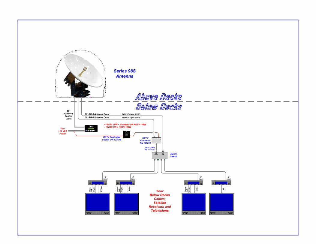
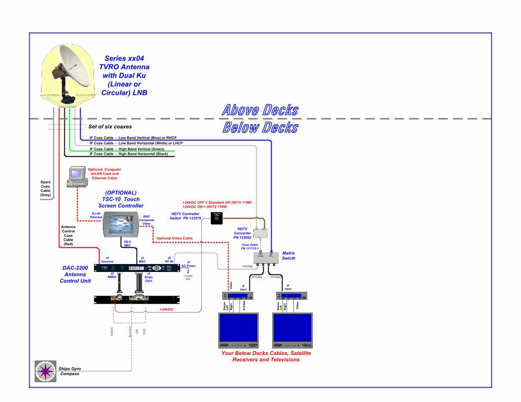
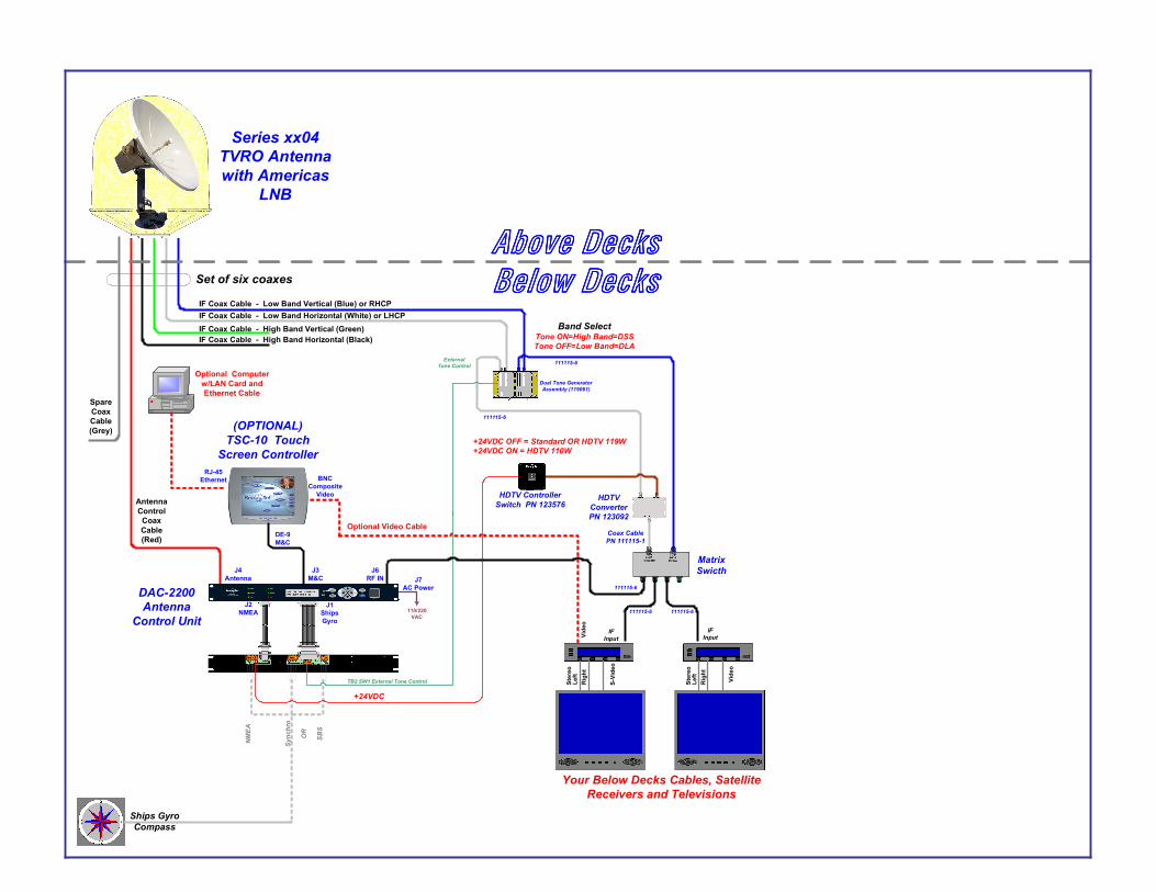
1.2. InstallationRefer to the Simplified Block Diagrams on the following pages.
1.2.1. HDTV Controller Switch Installation1 Connect the red wire from the switch to the DC Voltage source. In a Series 98S System, this
will be the +12 Volt DC supply that the Antenna Control Panel is connected to. In a Series 94,6003 or Series 04 System this will be the +24 VDC terminal of the 9-Pin Terminal MountingPCB on the Terminal Mounting Strip.
2 Connect the black from the switch to the “CONTROL” input on the HDTV 110 West Converter.
3 Mount the HDTV Controller Switch in a convenient location near the Antenna Control Unit (orAntenna Control Panel).
1.2.2. HDTV 110 West Converter Installation1 Disconnect the coax from the LHCP/Horizontal/18VDC input of your Matrix Switch and connect
it to the “INPUT” of the HDTV 110W Converter.
2 Connect the 111115 Coax provided in the kit from the “OUTPUT” of the HDVT 110W Converterto the LHCP/Horizontal/18VDC input on your Matrix Switch.
3 Mount the HDTV 110W Converter in a convenient location near your Matrix Switch.
1.3. Series98 Set-up and Operation
1.3.1. DirecTV Receiver SetupIn a single receiver installation, the receiver must be setup for dual, or triple, antenna/LNB operation so itwill output tone when you select a channel that will come from the secondary satellite (110W or 119W).You will set the THRES setting in the xx98 Antenna Control Panel to an even number value. However,Sea Tel recommends ALL systems be fitted with a Matrix Switch, even when one receiver will beconnected to the antenna.
In a multi-receiver installation with a matrix switch, all receivers must be setup for dual, or triple,antenna/LNB operation. You will set the THRES setting in the xx98 Antenna Control Panel to an oddnumber value so the antenna will NOT re-target automatically when one of the receivers output a tone.This will prevent multiple receivers from controlling the antenna. Satellite selection will be done manuallyfrom the Antenna Control Panel only.
2
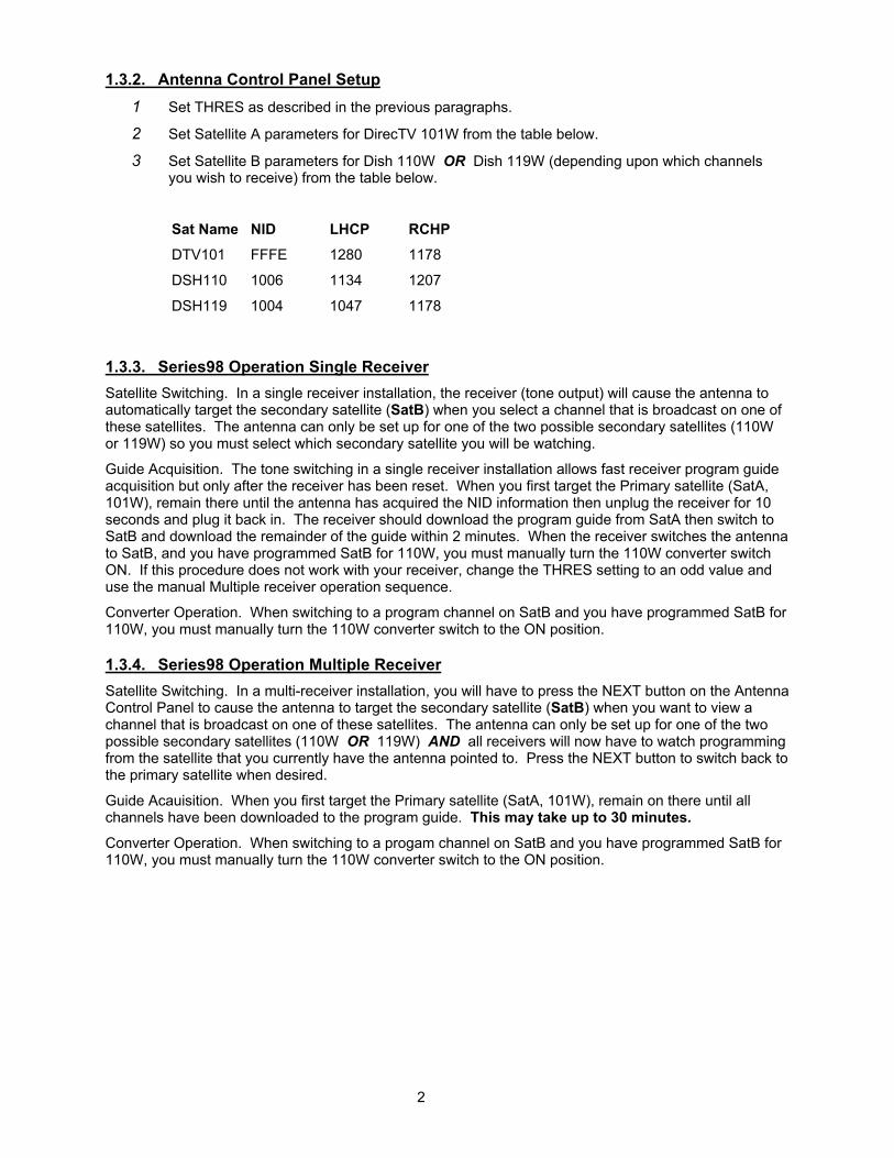
1.3.2. Antenna Control Panel Setup1 Set THRES as described in the previous paragraphs.
2 Set Satellite A parameters for DirecTV 101W from the table below.
3 Set Satellite B parameters for Dish 110W OR Dish 119W (depending upon which channelsyou wish to receive) from the table below.
Sat Name NID LHCP RCHP
DTV101 FFFE 1280 1178
DSH110 1006 1134 1207
DSH119 1004 1047 1178
1.3.3. Series98 Operation Single ReceiverSatellite Switching. In a single receiver installation, the receiver (tone output) will cause the antenna toautomatically target the secondary satellite (SatB) when you select a channel that is broadcast on one ofthese satellites. The antenna can only be set up for one of the two possible secondary satellites (110Wor 119W) so you must select which secondary satellite you will be watching.
Guide Acquisition. The tone switching in a single receiver installation allows fast receiver program guideacquisition but only after the receiver has been reset. When you first target the Primary satellite (SatA,101W), remain there until the antenna has acquired the NID information then unplug the receiver for 10seconds and plug it back in. The receiver should download the program guide from SatA then switch toSatB and download the remainder of the guide within 2 minutes. When the receiver switches the antennato SatB, and you have programmed SatB for 110W, you must manually turn the 110W converter switchON. If this procedure does not work with your receiver, change the THRES setting to an odd value anduse the manual Multiple receiver operation sequence.
Converter Operation. When switching to a program channel on SatB and you have programmed SatB for110W, you must manually turn the 110W converter switch to the ON position.
1.3.4. Series98 Operation Multiple ReceiverSatellite Switching. In a multi-receiver installation, you will have to press the NEXT button on the AntennaControl Panel to cause the antenna to target the secondary satellite (SatB) when you want to view achannel that is broadcast on one of these satellites. The antenna can only be set up for one of the twopossible secondary satellites (110W OR 119W) AND all receivers will now have to watch programmingfrom the satellite that you currently have the antenna pointed to. Press the NEXT button to switch back tothe primary satellite when desired.
Guide Acauisition. When you first target the Primary satellite (SatA, 101W), remain on there until allchannels have been downloaded to the program guide. This may take up to 30 minutes.Converter Operation. When switching to a progam channel on SatB and you have programmed SatB for110W, you must manually turn the 110W converter switch to the ON position.
3
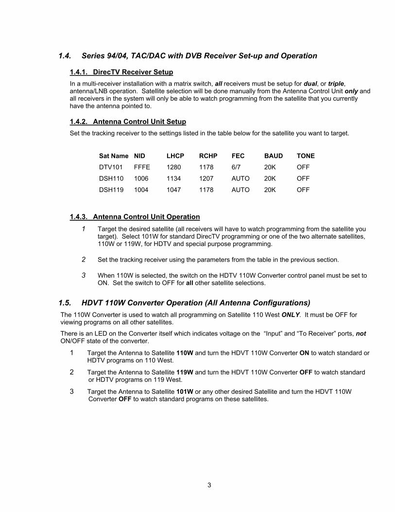
1.4. Series 94/04, TAC/DAC with DVB Receiver Set-up and Operation
1.4.1. DirecTV Receiver SetupIn a multi-receiver installation with a matrix switch, all receivers must be setup for dual, or triple,antenna/LNB operation. Satellite selection will be done manually from the Antenna Control Unit only andall receivers in the system will only be able to watch programming from the satellite that you currentlyhave the antenna pointed to.
1.4.2. Antenna Control Unit SetupSet the tracking receiver to the settings listed in the table below for the satellite you want to target.
Sat Name NID LHCP RCHP FEC BAUD TONE
DTV101 FFFE 1280 1178 6/7 20K OFF
DSH110 1006 1134 1207 AUTO 20K OFF
DSH119 1004 1047 1178 AUTO 20K OFF
1.4.3. Antenna Control Unit Operation1 Target the desired satellite (all receivers will have to watch programming from the satellite you
target). Select 101W for standard DirecTV programming or one of the two alternate satellites,110W or 119W, for HDTV and special purpose programming.
2 Set the tracking receiver using the parameters from the table in the previous section.
3 When 110W is selected, the switch on the HDTV 110W Converter control panel must be set toON. Set the switch to OFF for all other satellite selections.
1.5. HDVT 110W Converter Operation (All Antenna Configurations)The 110W Converter is used to watch all programming on Satellite 110 West ONLY. It must be OFF forviewing programs on all other satellites.
There is an LED on the Converter itself which indicates voltage on the “Input” and “To Receiver” ports, notON/OFF state of the converter.
1 Target the Antenna to Satellite 110W and turn the HDVT 110W Converter ON to watch standard orHDTV programs on 110 West.
2 Target the Antenna to Satellite 119W and turn the HDVT 110W Converter OFF to watch standardor HDTV programs on 119 West.
3 Target the Antenna to Satellite 101W or any other desired Satellite and turn the HDVT 110WConverter OFF to watch standard programs on these satellites.
Above DecksAbove DecksAbove DecksAbove DecksBelow DecksBelow DecksBelow DecksBelow Decks
Series 98SAntenna
IFInput
IFInput
Right
S-Video
Video
Left
Stereo
50' RG-6 Antenna Coax50'
AntennaControlCable
Your+12 VDCPower
50' RG-6 Antenna Coax
YourBelow Decks
Cables,Satellite
Receivers andTelevisions
MatrixSwitch
Right
Left
Stereo
IFInput
IFInput
Video
RF
Right
Left
Stereo
TVRO IF Signal (LHCP)
TVRO IF Signal (RHCP)
HDTVConverterPN 123092
HDTV ControllerSwitch PN 123576
Coax CablePN 111115-1
+12VDC OFF = Standard OR HDTV 119W+12VDC ON = HDTV 110W
Series xx04TVRO Antennawith Dual Ku
(Linear orCircular) LNB
AntennaControlCoaxCable(Red)
J6RF IN
Ships GyroCompass
NM
EA
Sync
hro
OR
SBS
110/220VAC
IF Coax Cable - High Band Horizontal (Black)IF Coax Cable - High Band Vertical (Green)
IF Coax Cable - Low Band Vertical (Blue) or RHCPIF Coax Cable - Low Band Horizontal (White) or LHCP
DAC-2200Antenna
Control Unit
Optional Computerw/LAN Card andEthernet Cable
J2NMEA
J1ShipsGyro
MatrixSwicth
IFInput
S-Vi
deo
Rig
htLe
ftSt
ereo
IFInput
Vide
o
Rig
htLe
ftSt
ereo
Your Below Decks Cables, SatelliteReceivers and Televisions
Above DecksAbove DecksAbove DecksAbove DecksBelow DecksBelow DecksBelow DecksBelow Decks
(OPTIONAL)TSC-10 Touch
Screen Controller
SpareCoaxCable(Grey)
J3M&C J7
AC Power
J4Antenna
DE-9M&C
RJ-45Ethernet BNC
CompositeVideo
Vide
o
Optional Video Cable
Set of six coaxes
111115-6 111115-6
111115-6
HDTVConverterPN 123092
+24VDC OFF = Standard OR HDTV 119W+24VDC ON = HDTV 110W
Coax CablePN 111115-1
+24VDC
HDTV ControllerSwitch PN 123576
Series xx04TVRO Antennawith Americas
LNB
AntennaControlCoaxCable(Red)
J6RF IN
Ships GyroCompass
NM
EA
Sync
hro
OR
SBS
110/220VAC
IF Coax Cable - High Band Horizontal (Black)IF Coax Cable - High Band Vertical (Green)
IF Coax Cable - Low Band Vertical (Blue) or RHCPIF Coax Cable - Low Band Horizontal (White) or LHCP
DAC-2200Antenna
Control Unit
Optional Computerw/LAN Card andEthernet Cable
J2NMEA
J1ShipsGyro
MatrixSwicth
IFInput
S-Vi
deo
Rig
htLe
ftSt
ereo
IFInput
Vide
o
Rig
htLe
ftSt
ereo
Your Below Decks Cables, SatelliteReceivers and Televisions
Above DecksAbove DecksAbove DecksAbove DecksBelow DecksBelow DecksBelow DecksBelow Decks
(OPTIONAL)TSC-10 Touch
Screen Controller
SpareCoaxCable(Grey)
J3M&C J7
AC Power
J4Antenna
DE-9M&C
RJ-45Ethernet BNC
CompositeVideo
Vide
o
Optional Video Cable
ExternalTone Control
TB2 SW1 External Tone Control
Set of six coaxes
Dual Tone GeneratorAssembly (119061)
Band SelectTone ON=High Band=DSSTone OFF=Low Band=DLA
111115-6 111115-6
111115-6
111115-6
111115-6
HDTVConverterPN 123092
+24VDC OFF = Standard OR HDTV 119W+24VDC ON = HDTV 110W
Coax CablePN 111115-1
+24VDC
HDTV ControllerSwitch PN 123576
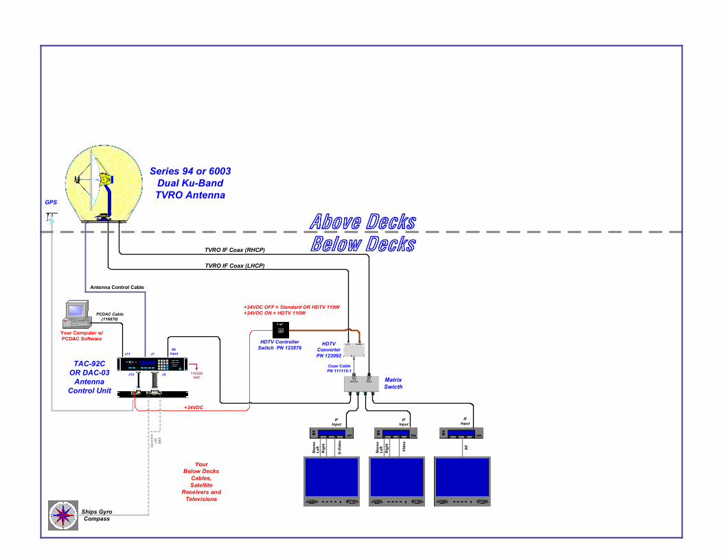
Series 94 or 6003Dual Ku-BandTVRO Antenna
Antenna Control Cable
J1RF
Input
PCDAC Cable(116670)
Ships GyroCompass
Syn
chro
OR
SBS
110/220VAC
J11
GPS
TAC-92COR DAC-03
AntennaControl Unit
Your Computer w/PCDAC Software
J13 J3
MatrixSwicth
IFInput
IFInput
Rig
ht
S-Vi
deo
Vide
o
Left
Ster
eo
Rig
htLe
ftSt
ereo
IFInput
RF
YourBelow Decks
Cables,Satellite
Receivers andTelevisions
TVRO IF Coax (LHCP)
TVRO IF Coax (RHCP)
Above DecksAbove DecksAbove DecksAbove DecksBelow DecksBelow DecksBelow DecksBelow Decks
HDTVConverterPN 123092
+24VDC OFF = Standard OR HDTV 119W+24VDC ON = HDTV 110W
Coax CablePN 111115-1
+24VDC
HDTV ControllerSwitch PN 123576