standard operating procedure eap059, version 1.2 operation
TRANSCRIPT

Standard Operating Procedure EAP059, Version 1.2
Operation of Mechanical Velocity Indicators
April 2018
Publication No. 18-03-211
Publication information This Standard Operating Procedure (SOP) is available on the Washington State Department of Ecology’s website at https://fortress.wa.gov/ecy/publications/SummaryPages/1803211.html. The Activity Tracker Code for this document is 16-057.
Contact information For more information contact:
Publications Coordinator Environmental Assessment Program P.O. Box 47600, Olympia, WA 98504-7600 Phone: (360) 407-6764
Washington State Department of Ecology - ecology.wa.gov o Headquarters, Olympia (360) 407-6000 o Northwest Regional Office, Bellevue (425) 649-7000 o Southwest Regional Office, Olympia (360) 407-6300 o Central Regional Office, Union Gap (509) 575-2490 o Eastern Regional Office, Spokane (509) 329-3400
Purpose of this document The Department of Ecology develops Standard Operating Procedures (SOPs) to document agency practices related to sampling, field and laboratory analysis, and other aspects of the agency’s technical operations.
Any use of product or firm names in this publication is for descriptive purposes only and does not imply endorsement by the author or the Department of Ecology.
Accommodation Requests: To request ADA accommodation including materials in a format
for the visually impaired, call Ecology at 360-407-6764. Persons with impaired hearing may call Washington Relay Service at 711. Persons with speech disability may call TTY at 877-833-6341.
Washington State Department of Ecology Environmental Assessment Program Standard Operating Procedure for Operation of Mechanical Velocity Indicators Version 1.2 Original Author – Zackary Holt, Robert Cusimano Date – 04/15/2013 Revision Author – Mitch Wallace Date – 04/25/2016 Reviewer – Charles W. Springer Date – 04/24/2013 QA Approval – William R. Kammin Date – 04/05/2015, 4/25/2016 EAP059 Recertification 04/03/2013 Recertification 04/25/2016 APPROVED Signatures on File

EAP059 – Operation of Mechanical Velocity Indicators – V1.2 – 04/25/2016 –Page 2 of 21
Uncontrolled copy when printed
Please note that the Washington State Department of Ecology’s Standard Operating Procedures (SOPs) are adapted from published methods, or developed by in-house technical and administrative experts. Their primary purpose is for internal Ecology use, although sampling and administrative SOPs may have a wider utility. Our SOPs do not supplant official published methods. Distribution of these SOPs does not constitute an endorsement of a particular procedure or method. Any reference to specific equipment, manufacturer, or supplies is for descriptive purposes only and does not constitute an endorsement of a particular product or service by the author or by the Department of Ecology. Although Ecology follows the SOP in most instances, there may be instances in which Ecology uses an alternative methodology, procedure, or process.

EAP059 – Operation of Mechanical Velocity Indicators – V1.2 – 04/25/2016 –Page 3 of 21
Uncontrolled copy when printed
SOP Revision History
Revision Date Rev
number Summary of changes Sections Reviser(s)
04-03-2013 1.1 Updated procedures relating to calibration and calibration verification of mechanical meters.
6 Jim Shedd
04-03-2013 1.1 Added Swoffer© Model 2100 Current, Velocity Meter Care and Calibration Procedure documentation to Appendix D.
Appendix D Jim Shedd
04-03-2013 1.1 Removed all language referring to the outdated Qwin discharge calculation program including instruction and documentation provided in Appendix D.
6.6 Appendix D.
Jim Shedd
04-03-2013 1.1 Updated citations and reference to 2012 edition of EAP Safety Manual.
9 and 10 Jim Shedd
04/03/2013 3-year review All Jim Shedd 04/22/2016 1.2 Updated citations and reference
to 2015 edition of EAP Safety Manual.
9 and 10 Mitch Wallace
04/22/2016 1.2 Removed all language referring to the Hydrological Services current meter.
2,3,4,5,6,and 10
Mitch Wallace
04/22/2016 1.2 3-year review All Mitch Wallace 04/22/2016 1.2 Recertified All Bill Kammin
EAP059 – Operation of Mechanical Velocity Indicators – V1.2 – 04/25/2016 –Page 4 of 21
Uncontrolled copy when printed
Environmental Assessment Program Standard Operating Procedure for Use of Mechanical Velocity Indicators 1.0 Purpose and Scope 1.1 This document is the Environmental Assessment Program (EAP)
Freshwater Monitoring Unit (FMU) Standard Operating Procedure (SOP) for use and maintenance of mechanical velocity indicators.
2.0 Applicability 2.1 Follow this SOP when sampling streamflow using the Swoffer 2100
velocity indicator. This document includes the approved methods for calibration, troubleshooting, and operation of all Swoffer 2100 velocity indicators currently in operation with the FMU.
3.0 Definitions 3.1 Fan – The propeller that attaches to the meter used to determine velocity. 3.2 Meter – The counting unit that attaches to the wading rod, bridge reel or
boat reel used to measure velocity. 3.3 CFS – Cubic feet per second 3.4 FPS – Feet per second 3.5 ADV – Acoustic Doppler Velocimeter. 4.0 Personnel Qualifications/Responsibilities 4.1 This type of field work requires a minimum of two technicians to safely
perform. 4.2 Training in the use of Swoffer equipment and hardware as well as
experience with flow sampling and streamflow gaging. 4.3 Training in safety procedures for working in wadeable streams, on
bridges, floating structures, and near/over open water. Personnel must also possess and properly employ the approved safety gear for each specific environment.
EAP059 – Operation of Mechanical Velocity Indicators – V1.2 – 04/25/2016 –Page 5 of 21
Uncontrolled copy when printed
4.4 Staff must understand and follow the Freshwater Monitoring Unit guidelines for streamflow monitoring outlined in the Quality Assurance Monitoring Plan.
5.0 Equipment, Reagents, and Supplies 5.1 Approved life jackets, waders, and foul weather gear. 5.2 Field Log Notebook with “Write in the rain” field forms. 5.3 300 ft. transect tape with tenths of a foot demarcation. 5.4 Tool box with listed tools present (Appendix B). 5.5 Replacement parts for hardware. 5.6 Swoffer 2100 velocity indicator. 5.7 Top set wading rod or bridge equipment with Swoffer 2100. 5.8 Swoffer 2100 connector cables (length dependent upon application). 5.9 Two 9 volt batteries. 5.10 Keys to access station house for data collection platforms (DCP). 6.0 Summary of Procedure 6.1 Trip Preparation 6.1.1 Prepare a field/float plan before embarking. This can
be found on the Ecology SharePoint site. 6.1.2 For Swoffer 2100: Set up a Swoffer fan on the wading
rod or bridge crane/board meter, and tighten the Allen set screw, taking care to not over tighten and damage or strip the threads in the meter.
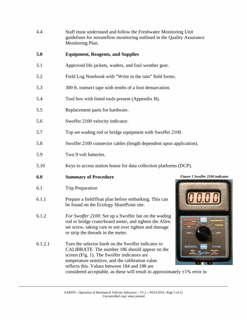
6.1.2.1 Turn the selector knob on the Swoffer indicator to
CALIBRATE. The number 186 should appear on the screen (Fig. 1). The Swoffer indicators are temperature sensitive, and the calibration value reflects this. Values between 184 and 188 are considered acceptable, as these will result in approximately ±1% error in
Figure 1 Swoffer 2100 indicator
EAP059 – Operation of Mechanical Velocity Indicators – V1.2 – 04/25/2016 –Page 6 of 21
Uncontrolled copy when printed
velocity. If the meter does not display a calibration value or the value is outside the acceptable ranges, change the 9-volt battery located in the back of the indicator and retry. This calibration number is discussed further in Appendix A.
6.1.2.2 Next, gently blow on the fan to make it spin. The fan should spin in the
meter with little breathing effort required. If there is difficulty or the fan seems sluggish, clean and inspect the rotor and inside the fan for dirt or damage. Replace the fan if necessary.
6.1.2.3 Thoroughly inspect the Swoffer cables and fittings for wear, and replace if
damaged, making sure to catalog what was broken and in need of repair/replacement.
6.1.2.4 Now you can perform a spin test to see if the sensor is working within
specified tolerances. Set the wading rod or bridge unit on a flat surface with the fan facing straight up. “Turn the indicator knob to count mode and blow very hard straight down on to the fan. The instant you stop blowing on the fan hit the reset key on the indicator and allow the rotor to coast to a stop,” notes Swoffer (2009). Any numbers greater than 400 are acceptable. If numbers do not exceed 400, replace the fan. Otherwise, lower stream velocities (<1.5ft/sec.) could be inaccurately measured. Retest until the readings are acceptable. You should check the fan regularly to avoid malfunctions.
6.1.2.5 Repack Swoffer and spare parts, removing the fan from the meter and
store it in a safe place. Make sure to include a spare 9-volt battery. Spin Test Parameters 6.1.3 Using the trip-packing lists (Appendices B, C) load the vehicle with the
necessary equipment/tools needed for the amount of stations you will visit, including one of the FlowTracker® ADV units used for calibration comparison with the mechanical instruments. Please see the FlowTracker SOP for pre-trip calibration and maintenance procedures.
6.2 Calibration and calibration verification of mechanical meters. 6.2.1 Swoffer indicators are calibrated by the user in accordance with
manufacturer’s instructions (Appendix D). Calibration is done initially upon receipt of the rotor assembly and the calibration number printed on the rotor fan. Before each use of a rotor assembly, ensure the calibration number is properly entered to the Swoffer indicator.
EAP059 – Operation of Mechanical Velocity Indicators – V1.2 – 04/25/2016 –Page 7 of 21
Uncontrolled copy when printed
6.2.2 The Freshwater Monitoring Unit independently verifies the calibration of mechanical instruments prior to each discharge measurement. Sample velocities from mechanical instruments are compared against samples from the reference standard FlowTracker® Acoustic Doppler Velocimeter (ADV). Refer to the FlowTracker® Standard Operating Procedure (Burks, 2009) for operating instructions.
6.2.3 Calibration verification is comprised of two velocity comparisons, one at a
velocity of less than approximately 1.5 fps and one at a velocity representing the estimated average velocity of the measurement. If the estimated average velocity is less than 1.5 fps, the results of the first comparison will suffice in lieu of the second comparison.
6.2.4 Locate water moving less than approximately 1.5 fps. Place the ADV at the
determined location, and record a velocity measurement. Follow up immediately in the same location with the mechanical meter. Take two 20-second measurements with the Swoffer indicator to compare with the 40-second ADV measurement. Average the two Swoffer readings. Note the calibration values on the discharge measurement form.
6.2.5 Next, find a location where velocity closely represents the estimated average
velocity. Again compare the mechanical velocity reading at that location with that of the ADV. Note these values on the discharge measurement form.
6.2.6 Calculate the percent error between the standard and the mechanical
equipment samples using the following equation:
𝐸𝐸 = �|𝑅𝑅 − 𝑆𝑆|𝑆𝑆
� ∗ 100
Where E = error expressed as percent, S = the standard measurement (ADV), and R = the reference measurement (mechanical instrument). Note the results on the discharge measurement form.
6.2.7 If the results of both comparisons show a difference of less than 10%, the calibration verification test for the measurement is complete. Continue to section 6.3 to begin the discharge measurement.
6.2.8 If either of the errors in comparative velocities are 10% or greater, repeat the
above procedure, perhaps in a different location. If either of the differences still exceeds the 10% threshold, replace the fan assembly and again perform the comparative tests. If no fan assembly is on hand that meets both 10% thresholds, perform the measurement with the assembly that compares most closely to the threshold. Rate the quality of the measurement, keeping in mind the potential error in velocity measurements. Take caution in determining if or to what degree such a measurement is used to develop or define a rating.
EAP059 – Operation of Mechanical Velocity Indicators – V1.2 – 04/25/2016 –Page 8 of 21
Uncontrolled copy when printed
6.2.9 In some cases, safety and practicality issues will preclude complete
calibration verification procedures at some measurement sites. It is acceptable to run verification tests at alternative locations before or after the measurement. Use judgment in rating the measurement if an alternative verification test is not representative of the velocities found at the measurement location.
6.2.10 In order to limit the likelihood of failed velocity comparisons with Swoffer
equipment, use relatively new rotor assemblies. Experience has shown newer rotor assemblies are more reliable.
6.2.11 Measurements are often conducted with Swoffer equipment by staff outside
of the Freshwater Monitoring Unit. In most of these instances, the ADV will be unavailable for premeasurement velocity comparisons. Calibration values will require regular checks to minimize measurement errors. Refer to Appendix E for these calibration instructions.
6.3 Collecting Streamflow Measurements with Mechanical Velocity
Indicators. 6.3.1 After successfully completing all of the steps in the Stream Hydrology
Site Visit SOP you are ready to take a streamflow measurement. Following the guidelines in the Measuring and Calculating Stream Discharge SOP you should have a suitable cross section set up and your descriptive notes taken.
6.3.2 Taking a Streamflow Measurement with a Swoffer 2100 Velocity
Indicator. 6.3.3 At the starting edge, measure depth at the first station and set the wading-
rod depth accordingly (see Measuring and Calculating Stream Discharge SOP and/or Bridge Measurement SOP’s for detailed descriptions).
6.3.4 Turn the indicator knob to the medium velocity setting on the meter (20
seconds). 6.3.5 After velocity is measured, the velocity value will appear on the LCD
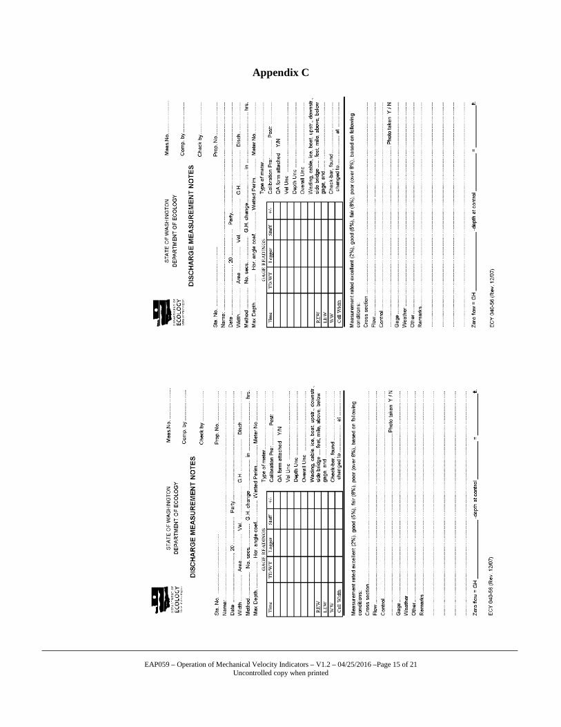
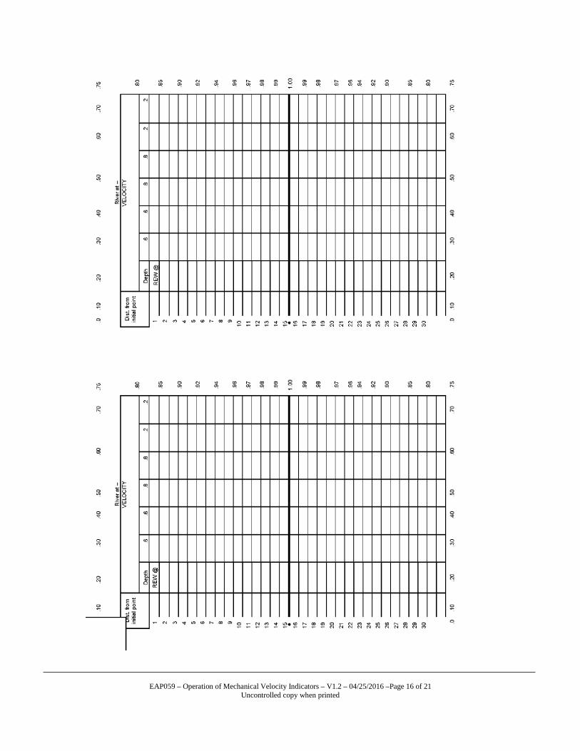
display. Record this value in your notes, and press the reset button again to collect the second measurement. Depress the reset button for each of the velocity measurements taken until the transect is completed. Record these numbers in the appropriate location on the field form (Appendix C).
6.4 Care and Storage of Mechanical Velocity Indicators
EAP059 – Operation of Mechanical Velocity Indicators – V1.2 – 04/25/2016 –Page 9 of 21
Uncontrolled copy when printed
6.4.1 Extreme temperatures effect mechanical velocity indicators causing drifting, sluggish LCD display time (in cold weather), poor battery performance, and loss of accuracy. Protect the meter from direct sunlight and heat as they can ruin the LCD display. Store the velocity indicators in the vehicle’s flow box to avoid damage. Do not use chemicals to clean the velocity indicators. A damp rag will suffice to wipe down the outside of the instrument. Periodically inspect the cable, meter, and its connectors for wear and tear. In extreme cold weather, keep the Swoffer meter inside of your coat to reduce the impacts of temperature on the calibration values. If the Swoffer meter is immersed in water, immediately disconnect the battery and dry the terminals, as well as the internal components of the meter. Air drying or heaters work the best for this. If obvious water infiltration into the LCD or window is observed the sensor needs complete drying. The circuit board may require repairs from the factory if this happens.
6.5 Data Management and Interpretation 6.5.1 Upon completion of the flow run, submit discharge measurement notes
(form ECY 040-56 (Rev. 12/07)) to the basin lead for entry and review. Calculate mechanical instrument discharge measurements in the Hydstra Data Management System’s Hygauge program.
6.5.2 All measurements are peer reviewed. Reviewed materials include
completed Discharge Measurement Notes and the Discharge Measurement Summary. Before review, enter the measurement into the Hydstra Gaugings database.
6.5.3 The reviewer checks measurement notes to ensure proper measurement
procedures were followed and the data reflects the assigned quality code. Check the Hydstra Gaugings database to verify measurement statistics, stage height, quality assignments, and notes. After verifying the Gaugings database, the reviewer enters his or her initials in the check box provided.
6.5.4 The reviewer compares the Hygauge Measurement Summary to the
Discharge Measurement Notes to evaluate potential discrepancies of location, depth, and velocity. Though it is the decision of the Basin Lead, the reviewer may suggest an alternative quality rating for the measurement.
6.5.5 When the review is complete, the reviewer initials the field-note sheet in
the space provided in the upper right corner and returns the submitted materials along with any written comments to the Basin Lead.
EAP059 – Operation of Mechanical Velocity Indicators – V1.2 – 04/25/2016 –Page 10 of 21
Uncontrolled copy when printed
6.6 Files for each measurement are electronically archived on the EAP SH-TCT shared server (H:\FLOWS\Projects), under the specific station name and water year in which the measurement was conducted.
6.7 A record of peer reviews of all discharge measurements is located in the EAP
SH-TCT shared server (H:\FLOWS\QAData). 7.0 Records Management 7.1 Processed files are saved in windows file system folders exclusive to
individual station visits. These files can be located within the FMU shared server.
7.2 Field log sheets are stored in the central filing locations at Ecology
headquarters and regional offices. 7.3 Quality checked and reviewed report storage is the responsibility of the
lead investigator in charge of the WRIA basin where the data was collected.
7.4 Records of all peer reviewed discharge measurements can be found in the
FMU shared server, as well as with the principal investigator responsible for them.
8.0 Quality Assurance and Quality Control 8.1 One of the most important parameters in assuring statistically relevant,
accurate data collection with mechanical measuring devices is consistent maintenance and calibration of all measuring components. Identifying a worn out fan, failing batteries, and worn cables is very necessary in attaining accurate data.
8.2 Assessment of sampling location and cross section characteristics are very
important factors in determining quality of data. The description and quality of these parameters are determined via professional rating as described in the Measuring and Calculating Stream Discharge SOP (Shedd, 2014). The field investigator considers factors such as cross-section quality and flow conditions as part of the quality assignment. Make sure to completely and concisely fill out the discharge measurement notes.
8.3 Upon completion of the flow measurement, turn in the measurement notes
and data collected to the principal investigator. The principle investigator will review the measurement and enter the flow measurement data and statistics to the Hydstra operating system.
EAP059 – Operation of Mechanical Velocity Indicators – V1.2 – 04/25/2016 –Page 11 of 21
Uncontrolled copy when printed
9.0 Safety 9.1 All field staff must understand and comply with the Environmental
Assessment Program (EAP) Safety Manual (2016). 9.2 All field staff must also possess the proper, up-to-date safety equipment
approved by the Stream Hydrology Unit safety officer and understand its complete operation.
EAP059 – Operation of Mechanical Velocity Indicators – V1.2 – 04/25/2016 –Page 12 of 21
Uncontrolled copy when printed
10.0 References 10.1 Burks, Tyler. 2015. Standard Operating Procedure for Measuring Stream
Discharge Using the Son-Tek FlowTracker Hand held ADV. Environmental Assessment Program, Washington State Department of Ecology. Document available at: ecology.wa.gov/quality.
10.2 Butkus, Steven. 2005. Quality Assurance Monitoring Plan – Stream Flow
Gaging Network. Environmental Assessment Program, Washington State Department of Ecology. Publication No. 05-03-204.
10.3 Environmental Assessment Program, 2016. Environmental Assessment
Program Safety Manual. 10.4 Myers, Jason. 2015. Standard Operating Procedure for Stream Hydrology
Site Visits. Environmental Assessment Program, Washington State Department of Ecology. Document available at: ecology.wa.gov/quality.
10.5 Shedd, James R. 2014. Standard Operating Procedure for Measuring and
Calculating Discharge. Environmental Assessment Program, Washington State Department of Ecology. Document available at: ecology.wa.gov/quality.
10.6 Instructions for Operation and Maintenance of 2100 Indicator. 2009.
Swoffer Instruments, Inc 1048 Industry Drive Seattle, Washington 98188, USA Document available at: www.swoffer.com.
EAP059 – Operation of Mechanical Velocity Indicators – V1.2 – 04/25/2016 –Page 13 of 21
Uncontrolled copy when printed
Appendix A
PRE/POST FIELD EXCURSION CHECKLIST Before embarking in the field all FMU staff must: 1. Arrange for lodging (if necessary). 2. Update Outlook calendar indicating basin location and duration of trip. 3. Prepare current rating curve sheets for basin. 4. Notify basin contacts (if necessary). 5. Prepare field/float plan form with emergency contact information for specific trip location and
duration. 6. Be sure to check van packing lists and pre-trip vehicle inspection before embarking from the
Operations Center.
Pre-Trip Vehicle Inspection: 1. Inspect tires for wear/damage on both sides of sidewall. Be sure to check tire pressure, as well. 2. Check fluid levels (oil, transmission, windshield washer, and radiator) before embarking, in order to
minimize possible breakdowns. 3. Make sure that the vehicle safety equipment is packed and that a spare tire, jack, and lug wrench are
in the van and in working order. 4. If any of these listed items are not in satisfactory working order, please notify Oliver Brock as soon
as possible. Do not embark with a vehicle that is in need of service or that may be damaged. Upon return from the field: End of Day— If staying at a hotel, notify your contact person each evening that you are finished with field sampling so they do not initiate the rescue protocol. If your trip is only a day trip, refer to end-of-trip protocol. End of Trip— • Fill vehicle with fuel before returning to the Operations Center. • Upon return to the Operations Center, please unload your gear and measuring equipment. • Don’t forget to download FlowTracker files to your laptop. • Unload spent batteries and carefully refill them with DI water, if needed. • Place spent batteries on appropriate chargers after servicing them. • Load spent desiccant (packs or loose crystals) into appropriate drying ovens, and check to be sure
that the oven temperatures are set correctly at the predetermined levels. • Hang any wet ropes to dry in their designated locations. • Store ADCP’s in their designated locations, tethered to the wall to prevent falling over. • Clean the interior of the van if needed. Wash vehicle if possible. • Close field/float plan, and notify contact person that your trip is over.
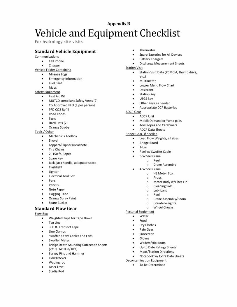
Appendix B
Vehicle and Equipment Checklist For hydrology site visits
Standard Vehicle Equipment Communications
• Cell Phone • Charger
Vehicle Folder Containing • Mileage Logs • Emergency Information • Fuel Card • Maps
Safety Equipment • First Aid Kit • MUTCD compliant Safety Vests (2) • CG Approved PFD (1 per person) • PFD CO2 Refill • Road Cones • Signs • Hard Hats (2) • Orange Strobe
Tools / Other • Mechanic’s Toolbox • Shovel • Loppers/Clippers/Machete • Tire Chains • 2- 150 ft. Ropes • Spare Key • Jack, jack handle, adequate spare • Flashlight • Lighter • Electrical Tool Box • Pens • Pencils • Note Paper • Flagging Tape • Orange Spray Paint • Spare Bucket
Standard Flow Gear Flow Box
• Weighted Tape for Tape Down • Tag Line • 300 ft. Transect Tape • Line Clamps • Swoffer Kit w/ Cables and Fans • Swoffer Meter • Bridge Depth Sounding Correction Sheets
(2/10, 6/10, 8/10’s) • Survey Pins and Hammer • FlowTracker • Wading rod • Laser Level • Stadia Rod
• Thermistor • Spare Batteries for All Devices • Battery Chargers • Discharge Measurement Sheets
Station Visit • Station Visit Data (PCMCIA, thumb drive,
etc.) • Multimeter • Logger Menu Flow Chart • Desiccant • Station Key • USGS key • Other Keys as needed • Appropriate DCP Batteries
ADCP Gear • ADCP Unit • MobileDemand or Yuma pads • Tow Ropes and Carabiners • ADCP Data Sheets
Bridge Gear, if needed • Lead Flow Weights, all sizes • Bridge Board • T-bar • Reel w/ Swoffer Cable • 3-Wheel Crane
o Reel o Crane Assembly
• 4-Wheel Crane o HS Meter Box o Props o Meter Body w/Fiber-Fin o Cleaning Soln. o Lubricant o Reel o Crane Assembly/Boom o Counterweights o Wheel Chocks
Personal Equipment • Water • Food • Dry Clothes • Rain Gear • Sunscreen • Gloves • Waders/Hip Boots • Up to Date Ratings Sheets • Maps/Station Directions • Notebook w/ Extra Data Sheets
Decontamination Equipment • To Be Determined
EAP059 – Operation of Mechanical Velocity Indicators – V1.2 – 04/25/2016 –Page 15 of 21
Uncontrolled copy when printed
Appendix C
EAP059 – Operation of Mechanical Velocity Indicators – V1.2 – 04/25/2016 –Page 16 of 21
Uncontrolled copy when printed
EAP059 – Operation of Mechanical Velocity Indicators – V1.2 – 04/25/2016 –Page 17 of 21
Uncontrolled copy when printed
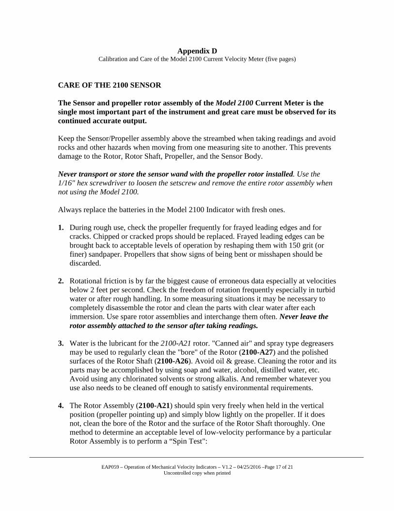
Appendix D Calibration and Care of the Model 2100 Current Velocity Meter (five pages)
CARE OF THE 2100 SENSOR The Sensor and propeller rotor assembly of the Model 2100 Current Meter is the single most important part of the instrument and great care must be observed for its continued accurate output. Keep the Sensor/Propeller assembly above the streambed when taking readings and avoid rocks and other hazards when moving from one measuring site to another. This prevents damage to the Rotor, Rotor Shaft, Propeller, and the Sensor Body. Never transport or store the sensor wand with the propeller rotor installed. Use the 1/16" hex screwdriver to loosen the setscrew and remove the entire rotor assembly when not using the Model 2100. Always replace the batteries in the Model 2100 Indicator with fresh ones. 1. During rough use, check the propeller frequently for frayed leading edges and for
cracks. Chipped or cracked props should be replaced. Frayed leading edges can be brought back to acceptable levels of operation by reshaping them with 150 grit (or finer) sandpaper. Propellers that show signs of being bent or misshapen should be discarded.
2. Rotational friction is by far the biggest cause of erroneous data especially at velocities
below 2 feet per second. Check the freedom of rotation frequently especially in turbid water or after rough handling. In some measuring situations it may be necessary to completely disassemble the rotor and clean the parts with clear water after each immersion. Use spare rotor assemblies and interchange them often. Never leave the rotor assembly attached to the sensor after taking readings.
3. Water is the lubricant for the 2100-A21 rotor. "Canned air" and spray type degreasers
may be used to regularly clean the "bore" of the Rotor (2100-A27) and the polished surfaces of the Rotor Shaft (2100-A26). Avoid oil & grease. Cleaning the rotor and its parts may be accomplished by using soap and water, alcohol, distilled water, etc. Avoid using any chlorinated solvents or strong alkalis. And remember whatever you use also needs to be cleaned off enough to satisfy environmental requirements.
4. The Rotor Assembly (2100-A21) should spin very freely when held in the vertical
position (propeller pointing up) and simply blow lightly on the propeller. If it does not, clean the bore of the Rotor and the surface of the Rotor Shaft thoroughly. One method to determine an acceptable level of low-velocity performance by a particular Rotor Assembly is to perform a “Spin Test":
EAP059 – Operation of Mechanical Velocity Indicators – V1.2 – 04/25/2016 –Page 18 of 21
Uncontrolled copy when printed
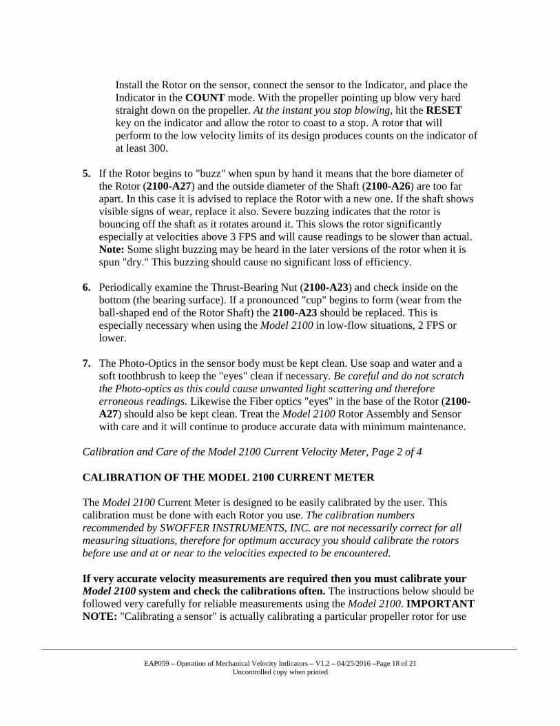
Install the Rotor on the sensor, connect the sensor to the Indicator, and place the Indicator in the COUNT mode. With the propeller pointing up blow very hard straight down on the propeller. At the instant you stop blowing, hit the RESET key on the indicator and allow the rotor to coast to a stop. A rotor that will perform to the low velocity limits of its design produces counts on the indicator of at least 300.
5. If the Rotor begins to "buzz" when spun by hand it means that the bore diameter of
the Rotor (2100-A27) and the outside diameter of the Shaft (2100-A26) are too far apart. In this case it is advised to replace the Rotor with a new one. If the shaft shows visible signs of wear, replace it also. Severe buzzing indicates that the rotor is bouncing off the shaft as it rotates around it. This slows the rotor significantly especially at velocities above 3 FPS and will cause readings to be slower than actual. Note: Some slight buzzing may be heard in the later versions of the rotor when it is spun "dry." This buzzing should cause no significant loss of efficiency.
6. Periodically examine the Thrust-Bearing Nut (2100-A23) and check inside on the
bottom (the bearing surface). If a pronounced "cup" begins to form (wear from the ball-shaped end of the Rotor Shaft) the 2100-A23 should be replaced. This is especially necessary when using the Model 2100 in low-flow situations, 2 FPS or lower.
7. The Photo-Optics in the sensor body must be kept clean. Use soap and water and a
soft toothbrush to keep the "eyes" clean if necessary. Be careful and do not scratch the Photo-optics as this could cause unwanted light scattering and therefore erroneous readings. Likewise the Fiber optics "eyes" in the base of the Rotor (2100-A27) should also be kept clean. Treat the Model 2100 Rotor Assembly and Sensor with care and it will continue to produce accurate data with minimum maintenance.
Calibration and Care of the Model 2100 Current Velocity Meter, Page 2 of 4 CALIBRATION OF THE MODEL 2100 CURRENT METER The Model 2100 Current Meter is designed to be easily calibrated by the user. This calibration must be done with each Rotor you use. The calibration numbers recommended by SWOFFER INSTRUMENTS, INC. are not necessarily correct for all measuring situations, therefore for optimum accuracy you should calibrate the rotors before use and at or near to the velocities expected to be encountered. If very accurate velocity measurements are required then you must calibrate your Model 2100 system and check the calibrations often. The instructions below should be followed very carefully for reliable measurements using the Model 2100. IMPORTANT NOTE: "Calibrating a sensor" is actually calibrating a particular propeller rotor for use

EAP059 – Operation of Mechanical Velocity Indicators – V1.2 – 04/25/2016 –Page 19 of 21
Uncontrolled copy when printed
with the Model 2100 Indicator. If you use more than one rotor assembly you must check the calibration for each rotor assembly, and adjust the Indicator Calibration Numbers accordingly as you switch from one propeller assembly to another. Calibration numbers correctly matching a rotor assembly to a 2100 indicator are especially important at the lower velocities (1.5 FPS and lower) and can vary greatly depending on many factors: bearing surface condition in the rotor, make-up of the water being measured (amount of suspended particulates), any damage to the propeller, rotor, shaft, thrust-bearing nut, etc. What a calibration number is: The Model 2100 rotors produce four pulses per revolution. Each of the four fiber optic “eyes” in the rotor triggers an electrical pulse from the sensor. These pulses are called “Counts” and are read by the Model 2100 Indicator. The Indicator uses these counts, measuring the number of them against an internal timer to determine velocity. The two calibration numbers in the Model 2100 therefore represent the number of counts a specific rotor produces as it travels through 10 feet and 10 meters of still water. When the sensor is stationary and water is moving past the propeller, a specific number of counts produced in a specific amount of time determines velocity when you know how many counts are produced per foot or meter (pitch). The calibration numbers then can also be referred to as Pitch. Although rotor/propeller combinations are “similar” they are not necessarily “identical” and therefore each may have a slightly different Calibration Number. Always remember that the Calibration Numbers shown on the Indicator’s display represent the Calibration Numbers for a single rotor assembly only. Double check all rotor assemblies used for any measuring job and make sure that each is within your accepted tolerance for calibration variation. Each rotor assembly may have a different calibration number. Only go out into the field with specific knowledge of each rotor assembly’s calibration number. Make sure that the calibration number in the 2100 Indicator matches the rotor that is attached to the sensor before relying on readings. CHECKING AND CHANGING CALIBRATION OF THEMODEL 2100 Before applying corrections to the Model 2100 rotate the selector switch to the CALIBRATE position. A figure will appear in the display and will be either the FEET calibration number or the METERS calibration number depending on the position of the FEET/METERS switch (located in the battery compartment). For most measuring applications the calibration numbers will be about:
FEET = 186 METERS = 610 If the displayed figures are much lower than these figures the first thing to check is the battery. A weak battery can allow the indicator calibration numbers to "drift" downward slightly and will cause errors in measurements. Be sure to connect the sensor to the indicator when confirming battery strength. Always keep a full charge 9-volt battery in the compartment as a spare. It is important to note that errors in measurements

EAP059 – Operation of Mechanical Velocity Indicators – V1.2 – 04/25/2016 –Page 20 of 21
Uncontrolled copy when printed
due to Calibration Number variation will be in direct percentage proportion to the difference between the ideal (correct) Calibration Number for any rotor assembly and the number that the indicator displays. Example: If the calibration number is 186 for a particular rotor assembly and the Indicator-displayed number is 184 then the velocity error due to calibration error will be about 1%.
METHOD To determine a reliable calibration number for your Model 2100 perform the following: This is something you must do if you are working with slow flows (below about 1.5 FPS) and for measurements taken in very shallow streams. Mark a straight course of 10 to 20 feet in length in a body of calm, current-free water along which the sensor can be towed by walking the course. A swimming pool or dock into a quiet lake serves well. Rotate the selector switch to the COUNT position. If the display does not show all zeroes press and release RESET. (The decimal point does not show in the count mode.)
Calibration and Care of the Model 2100 Current Velocity Meter, Page 3 of 4. Place the sensor in the water a few feet before the beginning of the course, 6 to 12 inches below the surface. Make sure that the wading wand remains vertical throughout the distance traveled and that the tip of the propeller rotor faces directly into the direction of travel… Do not "crab" the rotor in the stream as you walk. Begin walking the sensor through the course at a rate close to that which you will be measuring. If shallow flows are to be encountered try to duplicate those conditions when making calibration checks. Using the wand rather than the sensor as a guide, press and release RESET at the instant the wand enters the course. The indicator will begin counting the number of sensor pulses generated as you walk. At the instant the wand leaves the course, press and release START/STOP. The display now shows (and will hold) the number of pulses generated over the course length. Several passes through the course in both directions are recommended to develop a reliable average figure. Repeat the above process as many times as necessary to establish an average for each rotor assembly you are to use. Determine the average number of pulses generated through the course. If your course length is not 10 feet in length, compute the number of pulses that the sensor would generate if the course were exactly 10 feet. This will be the CALIBRATION NUMBER that the Model 2100 Indicator should hold for accurate measurements with that rotor assembly in feet per second:
FEET CAL. No. = 10 x AVERAGE No. OF PULSES ________________________________________________ COURSE LENGTH (IN FEET)
EAP059 – Operation of Mechanical Velocity Indicators – V1.2 – 04/25/2016 –Page 21 of 21
Uncontrolled copy when printed
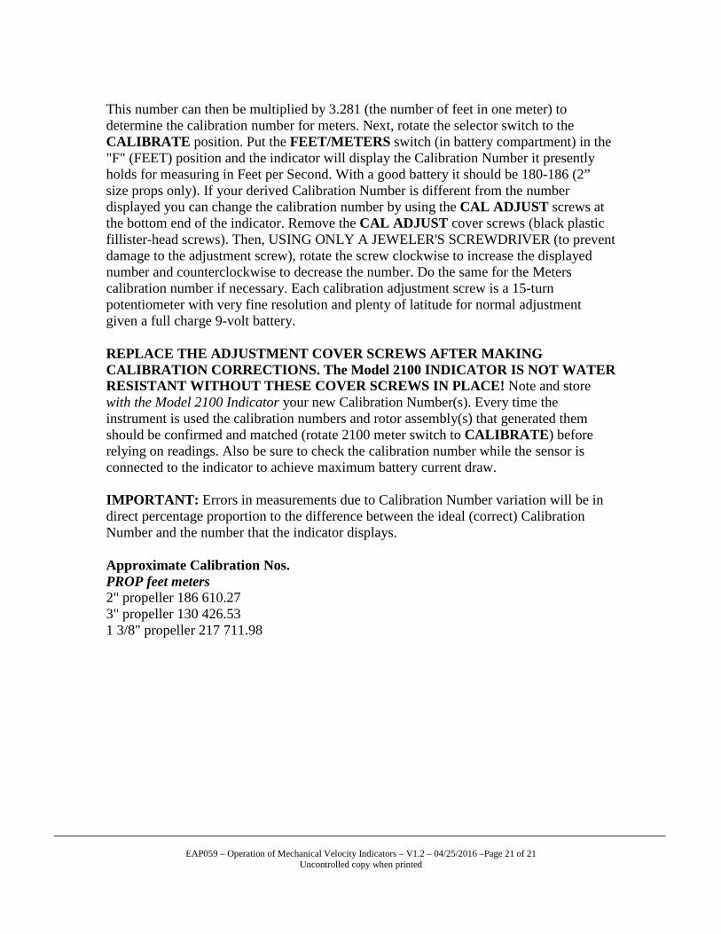
This number can then be multiplied by 3.281 (the number of feet in one meter) to determine the calibration number for meters. Next, rotate the selector switch to the CALIBRATE position. Put the FEET/METERS switch (in battery compartment) in the "F" (FEET) position and the indicator will display the Calibration Number it presently holds for measuring in Feet per Second. With a good battery it should be 180-186 (2” size props only). If your derived Calibration Number is different from the number displayed you can change the calibration number by using the CAL ADJUST screws at the bottom end of the indicator. Remove the CAL ADJUST cover screws (black plastic fillister-head screws). Then, USING ONLY A JEWELER'S SCREWDRIVER (to prevent damage to the adjustment screw), rotate the screw clockwise to increase the displayed number and counterclockwise to decrease the number. Do the same for the Meters calibration number if necessary. Each calibration adjustment screw is a 15-turn potentiometer with very fine resolution and plenty of latitude for normal adjustment given a full charge 9-volt battery. REPLACE THE ADJUSTMENT COVER SCREWS AFTER MAKING CALIBRATION CORRECTIONS. The Model 2100 INDICATOR IS NOT WATER RESISTANT WITHOUT THESE COVER SCREWS IN PLACE! Note and store with the Model 2100 Indicator your new Calibration Number(s). Every time the instrument is used the calibration numbers and rotor assembly(s) that generated them should be confirmed and matched (rotate 2100 meter switch to CALIBRATE) before relying on readings. Also be sure to check the calibration number while the sensor is connected to the indicator to achieve maximum battery current draw. IMPORTANT: Errors in measurements due to Calibration Number variation will be in direct percentage proportion to the difference between the ideal (correct) Calibration Number and the number that the indicator displays. Approximate Calibration Nos. PROP feet meters 2" propeller 186 610.27 3" propeller 130 426.53 1 3/8" propeller 217 711.98