installation & operation manual models: 60 - 119 rev d.pdf · installation & operation...
TRANSCRIPT

Installation & Operation ManualModels: 60 - 119
The information contained in this manual is intended for use by qualified professional installers, or service technicians. Consult your local expert for proper installation or service procedures.
� WARNING
Save this manual for future reference.
SJS-I-O Rev D
-- This storage tank MUST NOT be installed in any location where gasoline or flammable vapors are likely to be present.
-- WHAT TO DO IF YOU SMELL GAS
• Do not try to light any appliance.• Do not touch any electric switch; do not use any phone in your building.• Immediately call your gas supplier from a near by phone. Follow the gas supplier’s instructions.• If you cannot reach your gas supplier, call the fire department.• Installation and service must be performed by a qualified installer, service agency, or the gas supplier.
� WARNING: If the information in this manual is not followed exactly, a fire or explosion may result causing property damage, personal injury or loss of life.
®
LOW LEAD CONTENT

2
Hazard definitionsThe following defined terms are used throughout this manual to bring attention to the presence of hazards of various risk levels or to important information concerning the life of the product.
� DANGER
� WARNING
� CAUTION
CAUTION
NOTICE
DANGER indicates an imminently hazardous situation which, if not avoided, will result in death or serious injury.
WARNING indicates a potentially hazardous situation which, if not avoided, could result in death or serious injury.
CAUTION indicates a potentially hazardous situation which, if not avoided, may result in minor or moderate injury.
CAUTION used without the safety alert symbol indicates a potentially hazardous situation which, if not avoided, may result in property damage.
NOTICE indicates special instructions on installation, operation, or maintenance that are important but not related to personal injury or property damage.
ContentsCONTENTS ........................................................................ 2HAZARD DEFINITIONS ..................................................... 21. GENERAL INFORMATION ........................................ 3-4 Operating Restrictions .................................................. 4 2. INSTALLATION ............................................................. 5 Pre-Installation .............................................................. 5 Transporting and unpacking the unit ............................ 5 Examining the unit ....................................................... 5 Anchoring the unit ......................................................... 5 Recommended service clearances ............................. 5 Connecting the hot water source .................................. 6 Hot water outlet ............................................................ 6
Mixing valve .................................................................. 6 Aquastat / bulbwell ....................................................... 6 Piping the relief valve .................................................... 7 Drain ............................................................................. 7 Completing the installation ........................................... 7 3. OPERATION ................................................................. 8 Startup procedure .......................................................... 8 Shutdown procedure ...................................................... 8 4. INSPECTION ................................................................ 95. MAINTENANCE .......................................................... 10 Flushing the tank ........................................................ 10Revision Notes .................................................. Back Cover
Hot Water Can Scald!• Water heated to temperatures for clothes washing, dish washing, and other sanitizing needs can scald and cause permanent injury.• Children, elderly, and infirm or physically handicapped persons are more likely to be permanently injured by hot water. Never leave them unattended in a bathtub or shower. Never allow small children to use a hot water tap or draw their own bath.• If anyone using hot water in the building fits the above description, or if state laws or local codes require certain water temperatures at hot water taps, you must take special precautions: • Use lowest possible temperature setting. • Install some type of tempering device, such as an automatic mixing valve, at hot water tap or water heater. Automatic mixing valve must be selected and installed according to valve manufacturer’s recommendations and instructions.• Water passing out of drain valves may be extremely hot. To avoid injury: • Make sure all connections are tight. • Direct water flow away from any person.Protection Must Be Taken Against Excessive Temperature and Pressure!--Installation of a Temperature & Pressure (T&P) relief valve is required.
3
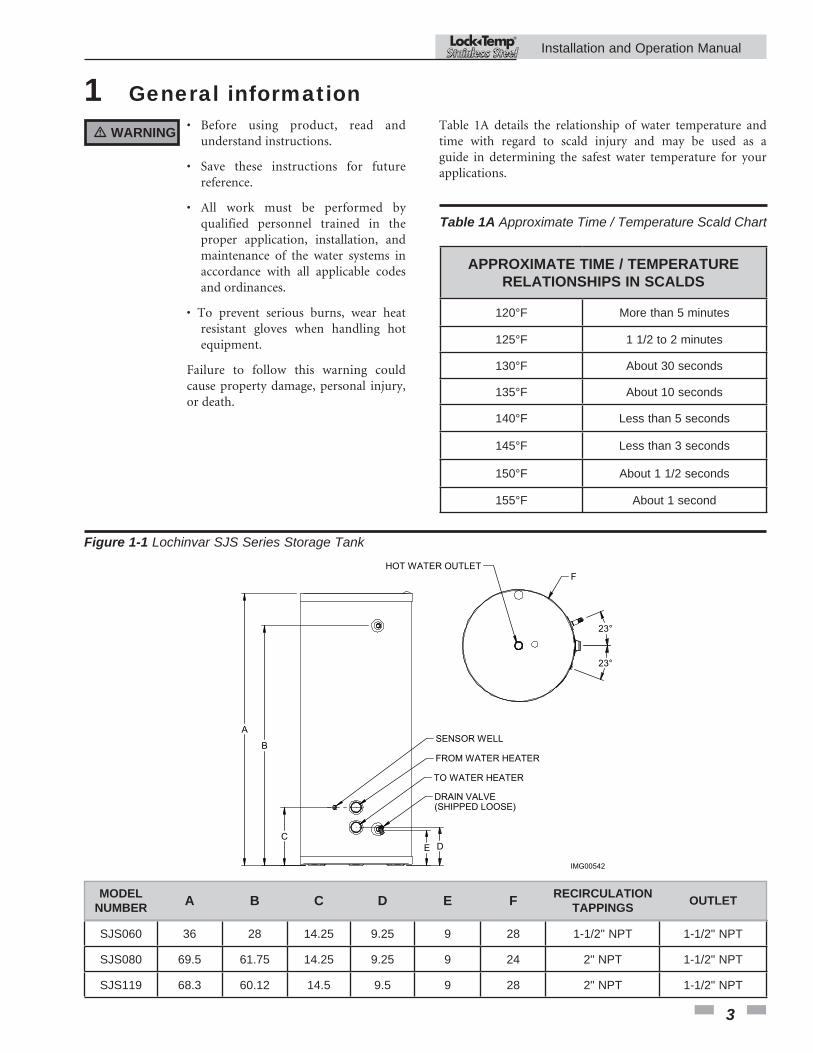
1 General informationTable 1A details the relationship of water temperature and time with regard to scald injury and may be used as a guide in determining the safest water temperature for your applications.
APPROXIMATE TIME / TEMPERATURE RELATIONSHIPS IN SCALDS
120°F More than 5 minutes
125°F 1 1/2 to 2 minutes
130°F About 30 seconds
135°F About 10 seconds
140°F Less than 5 seconds
145°F Less than 3 seconds
150°F About 1 1/2 seconds
155°F About 1 second
Table 1A Approximate Time / Temperature Scald Chart
Figure 1-1 Lochinvar SJS Series Storage Tank
IMG00542
B
A
C E D
F
SENSOR WELL
FROM WATER HEATER
TO WATER HEATER
DRAIN VALVE(SHIPPED LOOSE)
HOT WATER OUTLET
23°
23°
MODELNUMBER A B C D E F RECIRCULATION
TAPPINGS OUTLET
SJS060 36 28 14.25 9.25 9 28 1-1/2" NPT 1-1/2" NPT
SJS080 69.5 61.75 14.25 9.25 9 24 2" NPT 1-1/2" NPT
SJS119 68.3 60.12 14.5 9.5 9 28 2" NPT 1-1/2" NPT
� WARNING • Before using product, read and understand instructions.
• Save these instructions for future reference.
• All work must be performed by qualified personnel trained in the proper application, installation, and maintenance of the water systems in accordance with all applicable codes and ordinances.
• To prevent serious burns, wear heat resistant gloves when handling hot equipment.
Failure to follow this warning could cause property damage, personal injury, or death.
Installation and Operation Manual ®

4
� WARNING Areas of potential danger:
1. All water lines, joints, and valves.
2. If the unit has been in operation, allow the water in the heater and all components and surfaces (tank surface, water piping, etc.,) to cool before starting any maintenance procedures.
3. Assure that all power to associated water heating equipment has been shut off and disconnected before attempting any procedures.
4. Assure that all incoming and outgoing water lines have been shut off at the manual shutoff valves.
� WARNING Heated water presents situations that can be very dangerous due to the fact they are under pressure and at very high temperatures. To avoid possible injury or death, use common sense and follow all accepted and recommended procedures when performing installation, operation, and maintenance procedures.
� WARNING The combination of electricity and water can pose a very dangerous situation. Assure that all power has been shut off / disconnected from any associated water heater equipement before attempting any installation or maintenance procedures.
1 General informationThis manual is intended to cover installation, operation, and maintenance procedures for Lochinvar’s SJS Storage Tank. Instructions may not be specific to every system.
If questions are not answered by this manual, or if specific installation, operation, and/or maintenance procedures are not clearly understood, contact Lochinvar for clarification before proceeding.
Storage Tanks are designed for indoor use only. It should be located on a level surface (no more than one-half degree of slope), capable of supporting the total weight of the unit when filled to capacity.
The unit should be mounted to the floor following applicable architectural and local code requirements for the specific installation site. NOTE: Tanks do not come standard with floor tie downs.
For all piping connections, the use and/or type of joint compound or sealer on the joints should be determined by referring to local codes, accepted standards, and/or the requirements of the installing contractor.
Tank construction
Storage Tanks are pre-engineered and pre-assembled complete with all fittings. And like every Lochinvar product, they are thoroughly tested to ensure proper performance from the moment they are installed.
Gallon Capacities -- Lochinvar tanks are available in gallon capacities from 60 to 119 gallons.
Pressure Rating -- Lochinvar tanks are available with a maximum 150 psi working pressure.
Temperature Rating -- Lochinvar tanks are available with a maximum temperature of 210°F.
Tank -- Lochinvar tanks are constructed of 316L stainless steel with Polypropylene/ABS jackets to prevent rusting.
Insulation -- Tanks are insulated with a Polyeurethane foam mixture that has an R value of R-16. These tanks are for indoor installation only.
Relief Valve Tapping -- A tapping is provided for the installation of a factory supplied ASME/ANSI safety relief valve.
Hot Water Recirculation Tappings -- Lochinvar storage tanks will have two (2) tappings on the tank to provide recirculation piping between the tank and a hot water source.
Hot Water Outlet -- A Hot Water Outlet Tapping is positioned on the top of the tank for connection to the building system.
Drain -- A tapping or drain pipe will be connected to a low point on the tank for drainage.
Aquastat Bulbwell -- All Lochinvar tanks are provided with a bulbwell for the location of control sensors.
Installation and Operation Manual ®

5
Transporting and unpacking the unitEach jacketed Lochinvar SJS Storage Tank is cartoned as necessary at the factory. The carton is designed to provide protection for the unit during transportation, and to provide a safe means by which to lift and move the unit with a fork lift or hand truck.
Examining the unitAfter the unit has been uncartoned and set in place, it should be carefully examined to assure the tank has not been damaged during shipping. If any evidence of damage is detected that could affect the safe operation of the unit, contact Lochinvar , LLC., or your authorized sales representative, to report the damage and to receive instructions on how to proceed.
After the unit and all components have been inspected for damage, it is suggested that all optional or independent pressure and temperature control components be checked to assure that they meet or exceed design specifications. If any discrepancy is found, contact Lochinvar, LLC., or your authorized representative, before proceeding with the installation.
Anchoring the unitThe unit should be anchored to the floor, following applicable architectural / local code requirements, or accepted standards for the specific installation site. The unit should be installed in a location with sufficient clearance for service and repair.
Check local codes for Seismic anchoring requirements. If further assistance is needed, call the Lochinvar Technical Service Department and request a Seismic Report.
2 Installation
Pre-Installation1. The installation must conform to the instructions in this manual and all applicable local, state, provincial, and national codes, laws, regulations, and ordinances. Installations in Canada must conform to B149.2 Installation Code.
2. Be certain the domestic water supply to the tank has physical and chemical characteristics that fall within the limits shown in Table 2A. Where questions exist as to the composition of the water on the job, a qualified water treatment expert should be consulted.
Water with characteristics outside the limits shown in Table 2A may severely shorten the life of the tank due to corrosion. Damage to tanks in such cases is not covered under warranty.
3. Read and understand all installation requirements in this manual.
Table 2AWater Chemistry Requirements
Water used in the tank must have characteristics falling within the following limits:
Characteristic Min. Max.
Ph 6.0 8.0
Chloride (PPM) -- 80
CAUTION
Recommended clearancesThe installation location must provide adequate clearances for servicing and proper operation of the tank. A 12 inch vertical clearance is recommended from the top of the tank. A zero clearance is allowed for the sides of the tank.
Installation and Operation Manual ®
Locating the tank
The appliance MUST be located where leakage from the relief valve, leakage from related piping, or leakage from the tank or connections, will not result in damage to the surrounding areas, or to the lower floors of the building. A hot water storage tank should always be located in an area with a floor drain or installed in a drain pan suitable for water heaters. The manufacturer shall not be held liable for any such water damage.
CAUTION

6
Hot water outletThe next step in the installation process is to connect the hot water system piping to the hot water outlet port. The hot water supply tapping is located on top of the tank.
A manual shutoff valve should be installed downstream on the hot water outlet line as an isolation device in case the unit must be disconnected from the system. The shutoff valve should be in the closed position and remain so until the installation is complete.
Mixing valveField supplied. An anti-scald mixing valve is recommended when storing domestic hot water above 115°F.
Aquastat bulbwellReview the controls for the hot water source equipment. Some equipment or systems designs will require an independent aquastat (field supplied) to control the equipment. The aquastat may be surface mounted onto the jacket of the tank or a nearby surface. The water sensing probe may be installed in the 3/8" diameter dry bulbwell supplied with all Lochinvar Hot Water Storage Tanks. The equipment may employ a water sensing thermistor. The thermistor would be installed into the dry bulbwell and wired back to the hot water equipment.
2 Installation
� WARNINGBefore making any connections of water inlet or outlet to the unit, assure that all piping is clean and free of foreign material or scale. This can usually be accomplished by “blowing out” the pipe. Any foreign material or scale entering the unit can adversely affect operation and performance.
The two (2) tappings on the lower side of the tank shall provide recirculation between the tank and the water heating source. See example piping diagram between a storage tank and an indirect gas fired water heater (FIG. 2-1).
Connecting the hot water source
NOTICE See the Water Heater’s Installation and Operation manual for specific piping diagrams that match the inlet / outlet water tappings on the tank to the inlet / outlet water tappings on the water heater. Tapping locations on the water heater may vary by product or manufacturer.
Figure 2-1_Vertical Tank Piping Diagram
FLOW CHECKVALVE (TYPICAL)
EXPANSIONTANKTHERMOMETER
COLD WATERSUPPLY
HOT WATERSUPPLY
BUILDINGRETURN
RELIEFVALVE
FLOWSWITCH
WATERHEATER
CIRCULATOR
STORAGETANK
WATERHEATER
UNION(TYPICAL)
BALL VALVE(TYPICAL)
MIXING VALVE
Y-STRAINER[RECOMMENDED]
IMG00606
NOTICE For all piping connections, the use and / or type of joint compound or sealer on the joint should be determined by referring to local codes, accepted practices, or the requirements of the installing contractor.
If the cold water supply to the system is equipped with an in-line check valve or backflow preventer, a suitable expansion tank must be installed in the cold water supply line.
Installation and Operation Manual ®

7
� WARNING Do not install a manual shut off valve between the relief valve and the discharge. Doing so could cause serious injury or death if the relief valve released and the manual valve was closed. This would cause excessive buildup of pressure in the storage tank which could result in an explosion.
DrainThe tanks’ drain connection must be piped to a suitable floor drain. Brass drain cocks are acceptable. A brass full port ball valve is recommended to improve water flow.
Completing installationInstallation of the Lochinvar Hot Water Storage Tank is now complete. All documentation supplied with the unit should be passed along to maintenance personnel for future reference.
Piping the relief valve (Relief valve is field supplied)
All Lochinvar SJS Storage Tanks are equipped with a relief valve tapping on the tank. The valve should be piped to a discharge line leading to a suitable drain. Piping the pressure relief valve to a suitable drain will prevent both water and heat damage to the unit, as well as reduce the risk of injury from released heated water. The pipe must be of adequate size to properly handle the capacity of the relief valve and discharge line.
Check local codes to assure compliance. If a check valve has been installed on the inlet water line, thermal expansion may take place causing build up of excessive pressure when the water is being heated. This expansion will cause the relief valve to open, releasing hot water to the discharge line. A properly sized expansion tank must be installed to protect the system from water expansion.
2 Installation (continued)
Installation and Operation Manual ®

8
After all installation procedures have been completed, and all water piping to the energy source and power connections have been double checked, the unit is ready for operation. The following Startup Procedure focuses on the storage tank. Check the Installation and Operation Manual of the hot water source for additional startup and shutdown procedures.
Startup procedure1. Assure that all manual shutoff valves are closed.
2. Slowly open the manual shutoff valve on the cold water supply line and the valves in the hot water source recirculation piping. Check to assure that there are not leaks at the valve or any joints. Allow the tank to fill with water. As the tank is filling, hold the relief valve open to allow air to bleed out of the tank. Hot water faucets at the highest location in the building should also be opened. This will speed the filling process. Make sure the tank is full of water and free of air.
3. Open the manual shutoff valves.
4. Turn on the recirculation pump between the water heater and the tank.
After the power to the pump is turned on verify that the pump is working. If the pump is an oil lubricated unit, verify proper oiling.
� WARNING Heated water presents situations that can be very dangerous because of the high temperatures and pressures. Use common sense and follow all accepted and recommended procedures when performing installation, operation, and maintenance procedures to avoid possible injury or death.
Shutdown procedure
1. Turn off all power to the circulating pump and the hot water source controls.
2. Close all valves in the system in the following order: • the hot water outlet line; • the recirculation water piping
3. Relieve the pressure where possible.
4. After the system has cooled, drain the unit by opening the tank drain valve and holding the relief valve in the open position. This will prevent the formation of a vacuum and increase the drainage flow.
5. Proceed with the required maintenance or repairs.
6. After performing the required maintenance or repairs, return the unit to operation by following the Startup Procedure.
5. Follow the Startup procedure for the water heater to initiate a call for heat. Adjust the operating temperature control to the desired operating temperature and set the safety high limit.
6. As the unit is heating the water, carefully re-inspect water recirculation piping and the tank hot water outlet for signs of leakage.
7. As the unit approaches the desired operating temperature, adjust the temperature controls.
8. After the unit has reached operating temperature, re-inspect all joints for signs of leakage. In addition, check all gauges and controls to verify that the water temperature and pressure are within design specifications.
9. The unit is now ready for normal operation.
3 Operation
Installation and Operation Manual ®
9
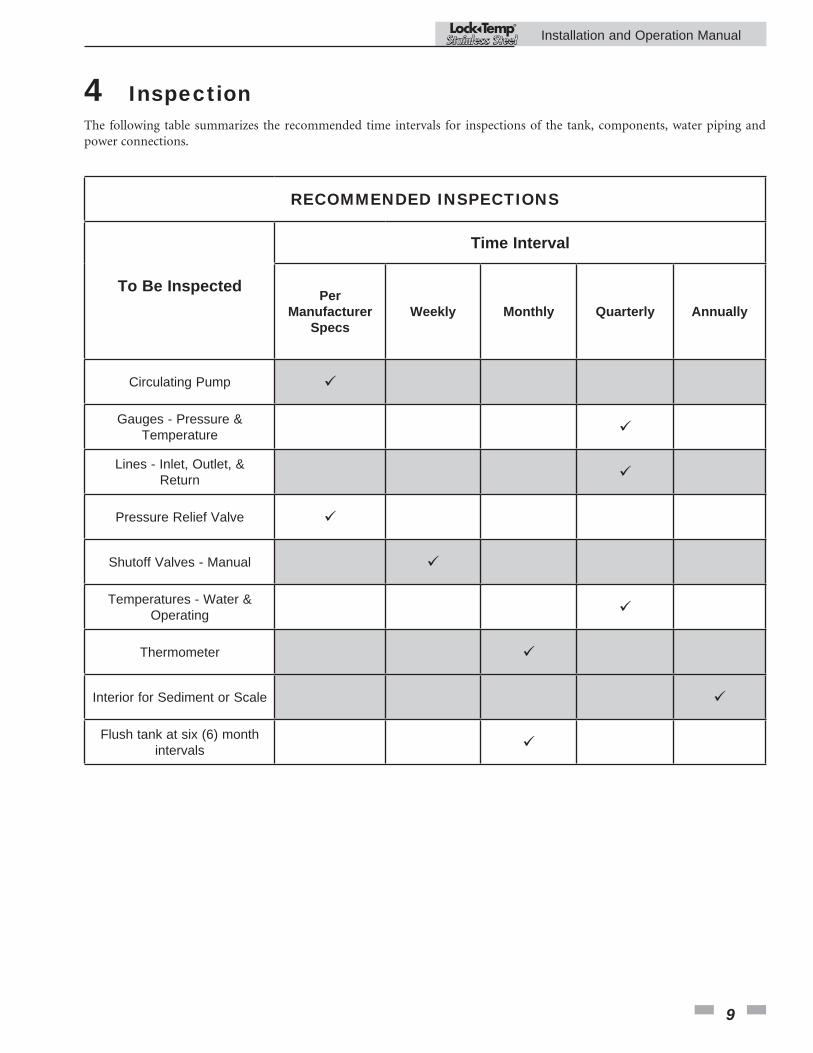
The following table summarizes the recommended time intervals for inspections of the tank, components, water piping and power connections.
RECOMMENDED INSPECTIONS
To Be Inspected
Time Interval
PerManufacturer
SpecsWeekly Monthly Quarterly Annually
Circulating Pump
Gauges - Pressure &Temperature
Lines - Inlet, Outlet, &Return
Pressure Relief Valve
Shutoff Valves - Manual
Temperatures - Water & Operating
Thermometer
Interior for Sediment or Scale
Flush tank at six (6) month intervals
4 Inspection
Installation and Operation Manual ®

10
5 MaintenanceA new tank installation should have a regular inspection program set up. The first inspection should be within the first three months of operation. Once the tendency to accumulate sediment has been established, the inspection program can be modified to suit the water conditions. Typical inspection programs flush the tank at six-month intervals and clean the tank in yearly intervals.
Deliming solvents or acid type flush agents are not recommended for use. These chemical cleaners are usually designed for use in non-potable systems such as heating boilers. These chemicals may be aggressive and cause damage to the tank.
� WARNING Hot water will be released under pressure. Avoid contact with the hot discharge water to prevent the risk of severe scald injury.
Flushing the storage tankSince mineral accumulation occurs in an un-fired tank it will be in a soft sediment form. This soft sediment can be removed by a regular flushing of the lower portion of the tank.
To flush the tank, follow these steps:
1. Turn off electrical power to the circulating pump and any other tank accessories.
2. Close the valve on the hot water outlet on top of the storage tank.
3. Ensure that the drain located on the bottom of the tank is routed to a floor drain with adequate capacity to allow the tank to be flushed.
4. Open the drain valve and allow the incoming cold water to flush the soft sediment out the bottom of the storage tank. Use extreme caution, as the water exiting the tank drain may be very hot. Avoid contact with the hot discharge water to prevent the risk of severe scald injury.
5. Observe the color of the water initially discharged from the tank drain. This water will generally be milky or slightly discolored by the sediment discharge. Allow the drain to run until the water runs clear.
6. Close the drain valve on the tank.
7. Open the hot water outlet valve on top of the tank.
8. Open an adjacent hot water tap to purge any air that may have entered the storage tank during the draining process. Close the hot water tap if no air discharge is observed.
9. Turn on electric power to the circulating pump and other electrical components if necessary.
10. Observe tank and piping to ensure all components are functioning properly.
Installation and Operation Manual ®

11
Notes
Installation and Operation Manual ®

Revision Notes: Revision A (ECO #C11841) initial release.
Revision B (ECO C11908) reflects the update of chart information in FIG. 1-1 on page 3 for SJS080.
Revision C (ECO #C12382) reflects the addition of the CSA Low Lead Content logo.
Revision D (ECO C15671) reflects the addition of the “Locating the tank” caution on page 5.
SJS-I-O Rev D
07/14