gsm-60 operation manual - enmet
TRANSCRIPT
ENMET 680 Fairfield Court Ann Arbor, MI 48108 734.761.1270 Fax 734.761.3220 www.enmet.com
GSM-60 Operation Manual
GSM-60 ENMET
Manual Revision Date – June 15, 2017 P a g e | 1 Manual Part No. – 80003-600 Rev. 1 – December 15, 2016
Table of Contents 1.0 INTRODUCTION .................................................................................................................................................................................... 3
1.1 Unpack ............................................................................................................................................................................................. 3 1.2 Check Order ..................................................................................................................................................................................... 3 1.3 Serial Numbers................................................................................................................................................................................. 3
2.0 INSTRUMENT FEATURES ..................................................................................................................................................................... 4 2.1 Exterior Features .............................................................................................................................................................................. 4 2.2 Display Panel Features ..................................................................................................................................................................... 4 2.3 Circuit Board Features ..................................................................................................................................................................... 6
3.0 INSTALLATION ..................................................................................................................................................................................... 7 3.1 Mounting of Instrument ................................................................................................................................................................... 7 3.2 Power Supply ................................................................................................................................................................................... 8 3.3 Inputs / Outputs ................................................................................................................................................................................ 8
3.3.1 Sensor/Transmitter Connection ...................................................................................................................................................................... 9 3.3.2 Relay Contacts ................................................................................................................................................................................................ 9 3.3.3 Optional 4-20mA Outputs ............................................................................................................................................................................. 10
3.4 Installation Verification ................................................................................................................................................................. 10 4.0 OPERATION ........................................................................................................................................................................................ 11
4.1 Normal Operation Condition ......................................................................................................................................................... 11 4.2 Alarm Set Points ............................................................................................................................................................................ 11 4.3 Alarm Latching or Differential Settings ........................................................................................................................................ 12 4.4 Audio Defeat .................................................................................................................................................................................. 12 4.5 Display ........................................................................................................................................................................................... 12 4.6 Operational Menu .......................................................................................................................................................................... 13 4.7 Fault Indications ............................................................................................................................................................................. 14
4.7.1 Low Flow Indication ..................................................................................................................................................................................... 14 4.7.2 Other Fault Indications ................................................................................................................................................................................. 14
4.8 Hydrocarbon Sensor Response ...................................................................................................................................................... 14 5.0 MAINTENANCE .................................................................................................................................................................................. 15
5.1 Cleaning Instructions ..................................................................................................................................................................... 15 5.2 Maintenance Menu ......................................................................................................................................................................... 15
5.2.1 Accessing Maintenance Menu ....................................................................................................................................................................... 15 5.2.2 Maintenance Menu Flow Chart .................................................................................................................................................................... 16
5.3 Calibration for CO, O2, HC and CO2 (Gas Channels) ..................................................................................................................... 17 5.3.1A Low Cal/Zero Cal Adjust ............................................................................................................................................................................ 18 5.3.1B High Cal/Span Gas Adjust .......................................................................................................................................................................... 19 5.3.2 Set 4 –20mA Transmitter Scale ..................................................................................................................................................................... 19 5.3.3 Set Alarm Points ........................................................................................................................................................................................... 20 5.3.4 Set Alarm Delay ............................................................................................................................................................................................ 22 5.3.5 Relay Configuration ...................................................................................................................................................................................... 23 5.3.6 Failsafe Configuration .................................................................................................................................................................................. 24 5.3.7 Set Output Span Range ................................................................................................................................................................................. 24 5.3.8 Set New Password ......................................................................................................................................................................................... 25 5.3.9 Exit Maintenance Menu ................................................................................................................................................................................ 25
5.4 Sensor Replacement ....................................................................................................................................................................... 26 5.4.1 Gas/Oxygen Sensor ....................................................................................................................................................................................... 26 5.4.2 Calibration/Sensor Replacement .................................................................................................................................................................. 26 5.4.3A Low Cal/Zero Cal Adjust ............................................................................................................................................................................ 28 5.4.3B High Cal/Span Gas Adjust .......................................................................................................................................................................... 29
5.5 Flow Control Orifice ...................................................................................................................................................................... 29 6.0 TECHNICAL DATA AND SPECIFICATIONS ......................................................................................................................................... 29 7.0 REPLACEMENT PART NUMBERS ....................................................................................................................................................... 30
7.1 ENMET part numbers for sensors and replacement parts: ............................................................................................................. 30 7.2 ENMET part numbers for Calibration equipment:......................................................................................................................... 30
APPENDIX A: CO CHARACTERISTICS .................................................................................................................................................... 31 APPENDIX B: GAS IONIZATION POTENTIALS ......................................................................................................................................... 32
GSM-60 ENMET
Manual Revision Date – June 15, 2017 P a g e | 2 Manual Part No. – 80003-600 Rev. 1 – December 15, 2016
List of Figures
Figure 1: External Features of the GSM-60 ....................................................................................................................... 5 Figure 2: GSM-60 Interior Features ................................................................................................................................... 6 Figure 3: GSM-60 Mounting Dimensions ......................................................................................................................... 7 Figure 2A: Relay, Input and Output Terminals .................................................................................................................. 8 Figure 4: GSM-60 Operational Display ........................................................................................................................... 11 Figure 5: GSM-60 Operation Menu Flow Chart .............................................................................................................. 13 Figure 6: GSM-60 Maintenance Menu Flow Chart. ........................................................................................................ 16 Figure 7: GSM-60 Calibration Connections .................................................................................................................... 18 Figure 9: Location of Gas Sensor and PiD(HC) Manifolds ............................................................................................. 26 Figure 7: GSM-60 Calibration Connections .................................................................................................................... 28 Figure 10: Carbon Monoxide Concentration.................................................................................................................... 31
List of Tables
Table 1 : Relay Failsafe Settings ...................................................................................................................................... 10 Table 2: Sensor Output .................................................................................................................................................... 10 Table 3: Typical Factory Alarm Set Points ...................................................................................................................... 11 Table 4: Factory Set Gas alarms Delay ............................................................................................................................ 22
Reference Information:
NOTE: [important information about use of instrument]
CAUTION: [affects equipment – if not followed may cause damage to instrument, sensor etc.…] WARNING: [affects personnel safety – if not followed may cause bodily injury or death.]
Attention / Warning Earth Ground
!

GSM-60 ENMET
Manual Revision Date – June 15, 2017 P a g e | 3 Manual Part No. – 80003-600 Rev. 1 – December 15, 2016
1.0 Introduction The GSM-60 is a sample draw monitoring instrument that measures and detects certain toxic hazards gases. The GSM-60 was designed primarily for monitoring one area with a single sampling hose, either for an individual gas or multiple gases. The instrument has one sampling pump and one flow sensor. The instrument is available with up to 4 internal sensors. Available sensors include, but are not, limited to carbon monoxide (CO), carbon dioxide (CO2), Hydrocarbons (HC) and variations in the oxygen (O2) content. The sensors can be used alone or up to four sensors can be used together. Some applications require monitoring of more than one area. If two sampling hoses are connected to one GSM-60 the flow sensor can only detect a total flow fault condition. For example, a pump failure or both sampling hoses being blocked. The system cannot detect a flow fault if only one of the two sampling hoses is blocked. Flowmeters should be installed in both sampling lines to provide a visual indication of proper flow. In the instrument, a 24 VDC sampling pump pass air over each sensor and the resulting electrical outputs are used to evaluate the air for the target gases. The GSM-60 is a highly adaptable instrument. Some adaptations require an addendum be added to the manual to facilitate use of the instruments with these adaptations. If addendum is needed, see page(s) between sections replacement part numbers and warranty. Some features of the instruments are as follows: continuous monitoring of the sample air alarm relay contacts available on terminals continuous LCD display of gas and vapor concentrations a fault relay and visual fault alarm menu driven operational and maintenance controls low air flow fault indication and display menu driven calibration procedure alarm acknowledgement capability including audio defeat audio and visual alarms indicate unsafe conditions mA outputs for each target gas Hydrocarbons (HC) are limited to gases with an ionization potential of 10.6 eV or less. See Appendix B for a list of gases and IPs. NOTE: All specifications stated in this manual may change without notice.
1.1 Unpack Unpack the GSM-60 and examine it for shipping damage. If such damage is observed, notify both ENMET customer service personnel and the commercial carrier involved immediately. Regarding Damaged Shipments
NOTE: It is your responsibility to follow these instructions. If they are not followed, the carrier will not honor any claims for damage.
• This shipment was carefully inspected, verified and properly packaged at ENMET and delivered to the carrier in good condition. • When it was picked up by the carrier at ENMET, it legally became your company’s property. • If your shipment arrives damaged:
o Keep the items, packing material, and carton “As Is.” Within 5 days of receipt, notify the carrier’s local office and request immediate inspection of the carton and the contents.
o After the inspection and after you have received written acknowledgment of the damage from the carrier, contact ENMET Customer Service for return authorization and further instructions. Please have your Purchase Order and Sales Order numbers available.
• ENMET either repairs or replaces damaged equipment and invoices the carrier to the extent of the liability coverage, usually $100.00. Repair or replacement charges above that value are your company’s responsibility.
• The shipping company may offer optional insurance coverage. ENMET only insures shipments with the shipping company when asked to do so in writing by our customer. If you need your shipments insured, please forward a written request to ENMET Customer Service.
Regarding Shortages If there are any shortages or questions regarding this shipment, please notify ENMET Customer Service within 5 days of receipt at the following address:
ENMET 680 Fairfield Court
Ann Arbor, MI 48108 734-761-1270 Fax 734-761-3220
Toll Free: 800-521-2978 1.2 Check Order Check, the contents of the shipment against the purchase order. Verify that the GSM-60 is received as ordered. If there are accessories on the order, ascertain that they are present. Check the contents of calibration kits. Notify ENMET customer service personnel of any discrepancy immediately. 1.3 Serial Numbers Each GSM-60 is serialized. These numbers are on tags on the equipment and are on record in an ENMET database.
GSM-60 ENMET
Manual Revision Date – June 15, 2017 P a g e | 4 Manual Part No. – 80003-600 Rev. 1 – December 15, 2016
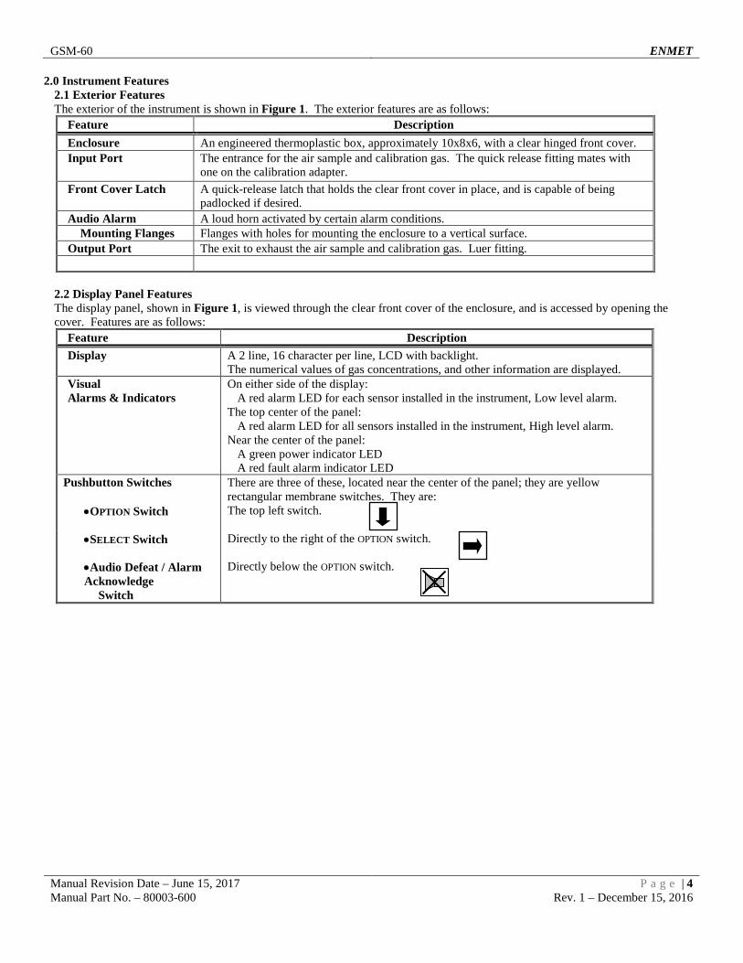
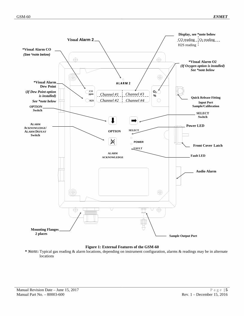
2.0 Instrument Features 2.1 Exterior Features The exterior of the instrument is shown in Figure 1. The exterior features are as follows:
Feature Description Enclosure An engineered thermoplastic box, approximately 10x8x6, with a clear hinged front cover. Input Port The entrance for the air sample and calibration gas. The quick release fitting mates with
one on the calibration adapter. Front Cover Latch A quick-release latch that holds the clear front cover in place, and is capable of being
padlocked if desired. Audio Alarm A loud horn activated by certain alarm conditions.
Mounting Flanges Flanges with holes for mounting the enclosure to a vertical surface. Output Port The exit to exhaust the air sample and calibration gas. Luer fitting.
2.2 Display Panel Features The display panel, shown in Figure 1, is viewed through the clear front cover of the enclosure, and is accessed by opening the cover. Features are as follows:
Feature Description Display A 2 line, 16 character per line, LCD with backlight.
The numerical values of gas concentrations, and other information are displayed. Visual Alarms & Indicators
On either side of the display: A red alarm LED for each sensor installed in the instrument, Low level alarm.
The top center of the panel: A red alarm LED for all sensors installed in the instrument, High level alarm.
Near the center of the panel: A green power indicator LED A red fault alarm indicator LED
Pushbutton Switches There are three of these, located near the center of the panel; they are yellow rectangular membrane switches. They are:
•OPTION Switch The top left switch.
•SELECT Switch Directly to the right of the OPTION switch.
•Audio Defeat / Alarm Acknowledge Switch
Directly below the OPTION switch.
GSM-60 ENMET
Manual Revision Date – June 15, 2017 P a g e | 5 Manual Part No. – 80003-600 Rev. 1 – December 15, 2016
Figure 1: External Features of the GSM-60 * NOTE: Typical gas reading & alarm locations, depending on instrument configuration, alarms & readings may be in alternate
locations
O2 %
CO ppm
Front Cover Latch
Quick Release Fitting Input Port
Sample/Calibration
Audio Alarm
Fault LED
SELECT Switch
Power LED
OPTION Switch
ALARM ACKNOWLEDGE/ ALARM DEFEAT
Switch
*Visual Alarm O2 (If Oxygen option is installed)
See *note below
*Visual Alarm CO (See *note below)
Mounting Flanges 2 places
H2S
*Visual Alarm Dew Point
(If Dew Point option is installed)
See *note below
Display, see *note below CO reading O2 reading H2S reading
Channel #1 Channel #3 Channel #4 Channel #2
Visual Alarm 2
A L A R M 2
OPTION SELECT
ALARM ACKNOWLEDGE
POWER
FAULT
Sample Output Port

GSM-60 ENMET
Manual Revision Date – June 15, 2017 P a g e | 6 Manual Part No. – 80003-600 Rev. 1 – December 15, 2016
2.3 Circuit Board Features The Display Panel is hinged on the left and is released by unscrewing the 2 screws located in the right corners. After releasing the panel, it is swung to the left, exposing the interior of the enclosure. The Circuit Board is mounted at the back surface of the enclosure interior. Features are shown in Figure 2.
Feature Description Relay Terminals This group of terminals is located at the left side of the Circuit Board.
For the contacts for each of four alarm relays, and for the contacts of a fault relay. Output Terminals One 4-20mA output per active channel. 2 channels/outputs per connector. HC Manifold Sensor Manifold
The PiD sensor is installed into this housing. The sample manifold, the carbon monoxide, carbon dioxide and oxygen sensors are located under this housing.
Filter, Particulate Removes contaminate from air sample line. Sensor Terminals J16, J18, J19
Sensor/Transmitter connectors 24VDC 4-20mA Input
Figure 2: GSM-60 Interior Features

GSM-60 ENMET
Manual Revision Date – June 15, 2017 P a g e | 7 Manual Part No. – 80003-600 Rev. 1 – December 15, 2016
3.0 Installation 3.1 Mounting of Instrument The GSM-60 should be located near the air to be monitored. Sampling lines should be no more than 50 feet long. It is recommended that Teflon® (PTFE) lined tubing be used. Quick disconnect fittings are supplied for use with 1/8” ID tubing. Mount the instrument on an appropriate vertical surface using the mounting flanges provided. Avoid areas with excessive vibration or temperature extremes. The holes in the flanges are 0.31 inch in diameter and form a 6 x 10.75-inch rectangle. See Figure 3. It is recommended to use #8 drywall anchors and screws for mounting the GSM-60 to a drywall/sheetrock surface.
Dimensions are in inches.
Figure 3: GSM-60 Mounting Dimensions
Mounting Holes 0.31” dia. 4 places

GSM-60 ENMET
Manual Revision Date – June 15, 2017 P a g e | 8 Manual Part No. – 80003-600 Rev. 1 – December 15, 2016
3.2 Power Supply The input power can vary from 100 to 240VAC, 50/60 Hz. Mains power should be connected to the Power Input Terminal J23 and the ground screw J21. See Figure 2 for location.
WARNING: Continuous gas detection and alarm systems (110VAC/220VAC / 24VDC/12VDC powered) become inoperative upon
loss of primary power. Contact factory for specifications and pricing of backup battery systems.
Upon supplying air and power to the instrument: The green power on LED is lit. The display backlight is lit, and instrument will step through a start-up sequence: unit serial number, software revision and gases
monitored may be shown on the display. The instrument may go into alarm briefly, but the sensors stabilize quickly. If the instrument persists in alarm, acknowledge the alarm by pressing the AUDIO DEFEAT / ALARM ACKNOWLEDGE switch. If alarm persists longer than 30 minutes, call ENMET customer service personnel.
3.3 Inputs / Outputs Two types of alarm outputs are available, relay contacts and 4-20mA outputs.
Figure 2A: Relay, Input and Output Terminals
Relay 1 Channel 1 Alarm 1
Relay 2 Channel 2 Alarm 1
Relay 3 Channel 3 Alarm 1
Relay 4 Channel 4 Alarm 1
Relay 5 Channel 1-4 Alarm 2
Relay 6 Ch 1-4 / System Fault
Input Connector 24VDC
GND mA
Input Connector 24VDC
GND mA
Input Connector 24VDC
GND mA
Connector 2 Channel 3 & 4 4-20mA Output
Connector 1 Channel 1 & 2 4-20mA Output
Connector RS485 Connector RS232
Connector RS485
Ground Screw J21
Power Input Terminal J23

GSM-60 ENMET
Manual Revision Date – June 15, 2017 P a g e | 9 Manual Part No. – 80003-600 Rev. 1 – December 15, 2016
3.3.1 Sensor/Transmitter Connection Sensor/Transmitters are connected to the GSM-60 control unit with two or three-conductor wiring, use the correct oil tight fitting. Size of wire depends on the distance between the sensor/transmitter and the control unit. See Recommended Wire Gauge Table below.
2 Wire for Sensors/Transmitter 3 Wire for Sensors/Transmitter Position Function Position Function
1 Power +24 VDC 1 Power +24 VDC 2 Not Used 2 Power Ground 3 Signal/Return to Ground 3 Signal
Recommended Wire Gauge
Distance from Sensor to Control Unit Recommended Wire Gauge < 500 feet 16 AWG 501 – 800 feet 14 AWG Longer Distances Contact Factory
NOTE: Sensor Location Gases have different densities. Some are heavier than air and concentrate at the bottom of a space. Some are lighter than air and gather at the top. Consider the density of the gas you want the sensor to detect when you install the sensor. Some examples are given below.
Heavier than Air Gas Sensor Location Bottled LP (liquefied petroleum) Interior wall; 18-24" from floor.
• DO NOT locate directly above or beside gas appliances (ovens, heaters).
• Avoid locating anywhere near a vent or window or near an outside doorway.
Propane Butane Gasoline Trichloroethylene Vaporized hydrocarbons Hydrogen sulfide
Lighter than Air Gas Sensor Location Natural gas (methane) Near ceiling.
• DO NOT locate directly above appliances where it is subject to direct exposure to heat or steam.
Ammonia Hydrogen
Same Density as Air Gas Sensor Location Carbon Monoxide 4-6 feet above the (generally uniform) floor.
• DO NOT locate in direct air currents of windows, doors, or vents.
If you have a question involving the location of a unit or sensor, please contact your distributor or ENMET personnel. A technician will analyze the question and recommend a location. 3.3.2 Relay Contacts Relay contacts are available for each alarm; these are SPDT, rated at 10Amp at 110VAC, and may be latching or non-latching as required by the application. They are accessed on the terminals next to each relay see Figure 2 & 2A. The contact positions are noted on the circuit board next to each terminal. Relays may also be configured as failsafe or non-failsafe. The default alarm relay configuration is for latching mode, and failsafe. They may be reconfigured in the maintenance menu. See section 5.3.5 & 5.3.6 The PC Board is labeled for the relays in their un-energized state. If the relay is configured for failsafe, then this is also the alarm condition state. Non-failsafe configured relays in the alarm state, are the reverse of the PC board labeling. Note that the Fault(FLT) relay cannot be set to operate in a Non-Failsafe mode. Please see the Table 1 on page 10:

GSM-60 ENMET
Manual Revision Date – June 15, 2017 P a g e | 10 Manual Part No. – 80003-600 Rev. 1 – December 15, 2016
Table 1 : Relay Failsafe Settings Position Failsafe-Alarm Non-Failsafe-Alarm J5 Relay 1 - NO Normally Open Normally Closed J5 Relay 1 - COM Common Common J5 Relay 1 - NC Normally Closed Normally Open J6 Relay 2 - NO Normally Open Normally Closed J6 Relay 2 - COM Common Common J6 Relay 2 - NC Normally Closed Normally Open J8 Relay 3 - NO Normally Open Normally Closed J8 Relay 3 - COM Common Common J8 Relay 3 - NC Normally Closed Normally Open J10 Relay 4 - NO Normally Open Normally Closed J10 Relay 4 - COM Common Common J10 Relay 4 - NC Normally Closed Normally Open J14 Relay 5 - NO Normally Open Normally Closed J14 Relay 5 - COM Common Common J14 Relay 5 - NC Normally Closed Normally Open J15 Relay 6/FLT - NO Normally Open N/A J15 Relay 6/FLT - COM Common N/A J15 Relay 6/FLT - NC Normally Closed N/A
Relays can be linked to specific alarms. The table below shows the default relay links. They may be changed in the maintenance menu if required. See Section 5.0.
Channel 1 Channel 2 Channel 3 Channel 4 Relay 1 Low Alarm Relay 2 Low Alarm Relay 3 Low Alarm Relay 4 Low Alarm Relay 5 High Alarm High Alarm High Alarm High Alarm
In addition, there is a fault relay, which changes state whenever the instrument is in a fault condition. The contact positions are noted on the circuit board next to each terminal. See Figure 2A. The coil of this relay is energized when the instrument is in the non-fault state; the contact conditions given on the circuit board next to the terminal, are for the non-energized state, which is identical to the fault state. These relay contacts can be used to operate auxiliary alarms or other functions. It is recommended that power for auxiliary equipment be supplied from an independent power source, separate from the GSM-60. Place a hole in the enclosure for a wire exit, and use appropriate cable fittings. Be sure to note the location and depth of hardware inside the enclosure. 3.3.3 Optional 4-20mA Outputs Isolated 4-20 mA outputs are available for data logging or other purposes. An output is supplied for each sensor supplied in an instrument, and can be added when a sensor is added in the field. These outputs are available on the Connector 1 for channels 1 & 2 and Connector 2 for channels 3 & 4. 4mA corresponds to a sensor reading at the bottom of the instrument range and 20mA corresponds to a full-scale reading. Standard ranges are shown in Table 2.
Table 2: Sensor Output Sensor 4mA 20mA CO 0 50 O2 0 30 CO2 0 5000 HC 0 100
Wiring requirements are the same as for the relays.
3.4 Installation Verification All instruments are calibrated at the factory. You may, if a calibration kit is available, calibrate the all gas channels of the instrument 24 hours after installation to verify proper installation and instrument operation. See Section 5.0, Maintenance, for calibration instructions. Calibration is also recommended after the first month of operation. Subsequent calibrations should be performed every 3 months. The dew point sensor cannot be calibrated in the field.
GSM-60 ENMET
Manual Revision Date – June 15, 2017 P a g e | 11 Manual Part No. – 80003-600 Rev. 1 – December 15, 2016
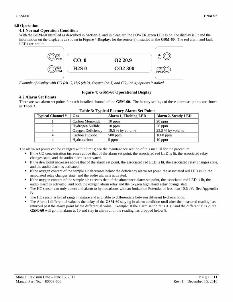
4.0 Operation 4.1 Normal Operation Condition With the GSM-60 installed as described in Section 3, and in clean air, the POWER green LED is on, the display is lit and the information on the display is as shown in Figure 4 Display, for the sensor(s) installed in the GSM-60. The red alarm and fault LEDs are not lit.
Example of display with CO (ch 1), H2S (ch 2), Oxygen (ch 3) and CO2 (ch 4) options installed
Figure 4: GSM-60 Operational Display 4.2 Alarm Set Points There are two alarm set points for each installed channel of the GSM-60. The factory settings of these alarm set points are shown in Table 3.
Table 3: Typical Factory Alarm Set Points Typical Channel # Gas Alarm 1, Flashing LED Alarm 2, Steady LED
1 Carbon Monoxide 10 ppm 20 ppm 2 Hydrogen Sulfide 10 ppm 20 ppm 3 Oxygen Deficiency 19.5 % by volume 23.5 % by volume 4 Carbon Dioxide 500 ppm 1000 ppm 4 Hydrocarbon 5 ppm 10 ppm
The alarm set points can be changed within limits; see the maintenance section of this manual for the procedure. If the CO concentration increases above that of the alarm set point, the associated red LED is lit, the associated relay
changes state, and the audio alarm is activated. If the dew point increases above that of the alarm set point, the associated red LED is lit, the associated relay changes state,
and the audio alarm is activated. If the oxygen content of the sample air decreases below the deficiency alarm set point, the associated red LED is lit, the
associated relay changes state, and the audio alarm is activated. If the oxygen content of the sample air exceeds that of the abundance alarm set point, the associated red LED is lit, the
audio alarm is activated, and both the oxygen alarm relay and the oxygen high alarm relay change state. The HC sensor can only detect and alarm to hydrocarbons with an Ionization Potential of less than 10.6 eV. See Appendix
B. The HC sensor is broad range in nature and is unable to differentiate between different hydrocarbons. The Alarm 1 differential value is the delay of the GSM-60 staying in alarm condition until after the measured reading has
returned past the alarm point by the differential value. Example: If the alarm set point is Λ 10 and the differential is 2, the GSM-60 will go into alarm at 10 and stay in alarm until the reading has dropped below 8.
CO 0 O2 20.9 H2S 0 CO2 300
CO PPM
O2 %
H2S PPM
CO2 PPM

GSM-60 ENMET
Manual Revision Date – June 15, 2017 P a g e | 12 Manual Part No. – 80003-600 Rev. 1 – December 15, 2016
4.3 Alarm Latching or Differential Settings An instrument is shipped with the alarms in the latching mode. The alarms may be independently configured in the non-latching mode or differential setting by use of the maintenance menu. See Section 5.3.3, for setting alarm 1 and alarm 2. Standard Setting IN THE LATCHING MODE: at the cessation of the condition which causes an alarm, the alarm indications do not cease, and the
alarm relay contacts do not revert to the non-alarm state, until the AUDIO DEFEAT / ALARM ACKNOWLEDGE switch is pressed. An alarm can also be acknowledged by pressing the switch during the alarm condition; then at the cessation of the alarm condition, alarm indications cease and alarm relays revert to the non-alarm state. After an alarm is acknowledged, alarms in the latching configuration are re-armed to latch at the next alarm condition.
IN THE NON-LATCHING MODE: at the cessation of the condition that causes an alarm, the alarm indications automatically cease, and the alarm relay contacts revert to the non-alarm state.
Differential Setting The Alarm 1 differential value is the delay of the GSM-60 staying in alarm condition until after the measured reading has
returned past the alarm point by the differential value. Example: If the alarm point is Λ 10 and the differential is 2, the GSM-60 will go into alarm at 10 and stay in alarm until the reading has dropped below 8.
4.4 Audio Defeat Pressing the AUDIO DEFEAT / ALARM ACKNOWLEDGE switch during an alarm temporarily silences the audio alarm. Relays and alarm LEDs continue to function, in the alarm state, during an alarm condition. If the alarm condition persists, the audio alarm will “chirp” every 20 seconds. If after 15 minutes the alarm condition continues the audio alarm will reactivate at full intensity. If any other alarm condition occurs while the audio alarm has been silenced it will force the audio alarm to reactivate
immediately.
4.5 Display In clean air a display is shown in Figure 4. This position of the display is termed the "operational display". As explained below, the display can be used to view other information by using the OPTION and SELECT switches. Concentrations of CO and CO2 are given in PPM (parts per million parts of air). Dew point is given in degrees Fahrenheit at 55 PSIG; this can be changed to degrees Centigrade by pressing the SELECT switch. Oxygen concentration is given in percent by volume. When sample flow is reduced below a limit, the bottom line of the display flashes “Low Flow Alarm”.

GSM-60 ENMET
Manual Revision Date – June 15, 2017 P a g e | 13 Manual Part No. – 80003-600 Rev. 1 – December 15, 2016
4.6 Operational Menu The operational menu allows the user to: View alarm set point concentration values View alarm ascending/descending trigger, latching and delay configurations Enter the maintenance menu with the proper Password.
The operational menu is accessed with the OPTION and SELECT switches. The operational menu flow chart is shown in Figure 5, Pressing the OPTION switch is indicated with a "O" Pressing the SELECT switch is indicated with a "S".
If the instrument is left at any location in the operational or maintenance menus, other than the operational display, with no action taken for a period of 45 seconds, it returns to the operational display.
Figure 5: GSM-60 Operation Menu Flow Chart
O
S CH-1 CH-3 CH-2 CH-4 O = Press Option switch
S = Press Select switch
O
No Function
ΛL10 A1 vL19.5 vL-40 ΛD 500
O
No Function
S
S ΛL20 A2 Λ 23.5 ΛL39 Λ 1000
O
No Function
S Enter Maint Menu Enter Password _
See Maintenance Menu Diagram
O
S for each active channel CH1 SCALE (CO) 0 – 50 PPM
S CH3 SCALE (O2)
CH2 SCALE (H2S) 0 – 50PPM
S CH4 SCALE (CO2) 0 – 5000 PPM
S
O
O
O
Displays are examples of gases: Channel 1 = Carbon Monoxide Channel 2 = Hydrogen Sulfide Channel 3 = Oxygen Channel 4 = Carbon Dioxide Displays are examples of Alarms
Λ - Indicates alarm triggered on increasing value of reading
v - Indicates alarm triggered on decreasing value of reading
Displays are examples of Alarms L – Indicates alarm is in latching
mode. (no L present) – Indicates alarm
is in non-latching mode. Displays are examples of Alarms
D – Indicates alarm is in Differential Setting.
(no D present) – Indicates alarm is in Standard Setting.
ALARM1 Delays (Seconds)
O
S No Function
S 50 mASPAN 30.0 68 5000
O
No Function
5 5 5 5
Alternating
S Relays 123456 [=ON [[[[[[
O
No Function

GSM-60 ENMET
Manual Revision Date – June 15, 2017 P a g e | 14 Manual Part No. – 80003-600 Rev. 1 – December 15, 2016
4.7 Fault Indications 4.7.1 Low Flow Indication A flow sensor is used to furnish a low flow indication. When the sample air pressure drops below preset levels, the fault light and audio alarm are activated, and the display flashes “Low Flow Alarm”. If two sampling hoses are connected to one GSM-60, the flow sensor can only detect a total flow fault condition. For example: a pump failure or both sampling hoses being blocked. The system cannot detect a flow fault if only one of the two sampling hoses is blocked. 4.7.2 Other Fault Indications Other fault indications are associated with sensor zero and calibration activities, and are described in the maintenance Section 5.0 of this manual.
4.8 Hydrocarbon Sensor Response If a Hydrocarbon (HC) sensor is supplied with the GSM-60 instrument, it designed to detect hydrocarbon gases and vapors with an ionization potential (IP) of 10.6 eV or less. Hydrocarbons with an IP of greater than 10.6 eV will NOT be detected. Please see Appendix B for a list of common gases and vapors and their respective IP rating. Unless otherwise noted Isobutylene is used as a calibration and reference gas.

GSM-60 ENMET
Manual Revision Date – June 15, 2017 P a g e | 15 Manual Part No. – 80003-600 Rev. 1 – December 15, 2016
5.0 Maintenance The GSM-60 requires periodic sensor calibration and replacement. Calibration of toxic gas and oxygen sensor should be performed immediately following installation, one month after installation and every 3 months thereafter. HC sensor should be calibrated monthly. Oxygen and CO sensor have an estimated lifetime of 1 – 2 years. The CO2 sensor has an estimated lifetime of 3 years. Other sensors vary. Sensors should be replaced when they will not calibrate or shortly before the end of the estimated lifetime.
5.1 Cleaning Instructions CAUTION: Never spray a cleaning solution on the surfaces of the GSM-60 devices.
Clean the exterior of the GSM-60 enclosures with a mild soap solution on a clean, damp cloth. Do not soak the cloth with solution so that moisture drips onto, or lingers on, external surfaces. Under no circumstances should organic solvents such as paint thinner be used to clean instrument surfaces.
5.2 Maintenance Menu 5.2.1 Accessing Maintenance Menu The GSM-60 maintenance menu is accessed by entering the proper password with the OPTION and SELECT switches. See Section 5.2.2 Figure 6 for full Maintenance Menu flow chart. Entrance to the maintenance menu is guarded with a four-digit Password. The factory default setting of the password is 1270. When a valid numerical password is inserted, the user can enter the maintenance menu. To enter the maintenance menu. Press the OPTION switch until “Enter Maint Menu” is displayed then press SELECT switch for the Enter Password menu. Enter the valid password as described below. In the "Enter Maint Menu" position Press the SELECT switch "Enter Password ζ 0" is displayed. Press SELECT switch once, to move cursor to next digit, this
will be the first digit of the password. In the ζ000 position, the underline cursor is under the left digit. Press the OPTION switch to change the left digit; select the correct digit. Press the SELECT switch, which locks the digit in place and moves the cursor one digit to the right. Continue this process until the four-digit password is complete. When a valid password is inserted in this manner, the display is transferred to the "Calibration" portion of the menu. If an invalid password is inserted, you are returned to the Enter Maint Menu display.
Example: Password Display (with factory installed password entered) and Flow Chart below. To Calibration See Section 5.2.2 Figure 6 for full Maintenance Menu flow chart.
Enter Password 1270
CO PPM
O2 %
O = Option Switch S = Select Switch
H2S PPM
O S
S Enter Password
ζ0000
Enter Maint Menu Changes digit indicated by underscore cursor
Locks underscored digit and moves cursor to next digit O(6)
Valid
Invalid
!

GSM-60 ENMET
Manual Revision Date – June 15, 2017 P a g e | 16 Manual Part No. – 80003-600 Rev. 1 – December 15, 2016
5.2.2 Maintenance Menu Flow Chart The maintenance menu diagram is shown in Figure 6 Maintenance Menu Flow Chart. From the operational display, press the OPTION switch 6 times; "Enter MAINTENANCE Menu" is displayed.
Figure 6: GSM-60 Maintenance Menu Flow Chart.
O = Press Option S = Press Select
OS
MAINTENANCE MENU
Exit maint menu
Press OPTION to return to top of maintenance menu.Press SELECT to return to operational menu.See Section 5.3.9 for instructions on how to exit Maintenance Menus.
To/FromOperational
DisplayFrom Operational MenuPress OPTION (6 times)
SEnter Maint MenuO
SEnter Password
0000
Changes digit indicated by underscore cursor
Locks underscored digit and moves cursor to next digit
O(6)
Valid
Invalid
O
SMAINTENANCE MENU
Set New Password
Password XXXX
OS
Changes digit indicated by underscore cursorLocks underscored digit and moves cursor to next digitSee Section 5.3.8 for changing password instructions.
O
S Calibration
Select (Gas)
MAINTENANCE MENU
CalibrationPress OPTION until the channel to be Calibrated is displayedSee Section 5.3 for calibration instructions.
O
SMAINTENANCE MENU
Set Alarm1
Alarm 1Select: XX
Press OPTION until the gas alarm to be Set is displayedSee Section 5.3.3 for setting alarms instructions.
O
S Alarm 2Select: XX
MAINTENANCE MENU
Set Alarm2Press OPTION until the gas alarm to be Set is displayedSee Section 5.3.3 for setting alarms instructions.
O
SMAINTENANCE MENU
Set Alarm Delays
Alarm DelaySelect: XX
Press OPTION until the gas alarm delay to be Set is displayedSee Section 5.3.4 for setting alarms instructions.
O
SMAINTENANCE MENU
Configure Alarms
Ch 1, 2, 3, 4R1 L
Pressing OPTION changes letter indicated by underscore cursorSee Section 5.3.5 for configuring relay instructions.
O
SMAINTENANCE MENU
Relay Failsafes
Relay FailsafesR:1 Failsafe ON
Pressing OPTION changes Failsafe setting from ON to OFFSee Section 5.3.6 for configuring relay failsafe instructions.
MAINTENANCE MENUScale mA Xmtrs
Press OPTION until gas to be Set-Up is displayedSee Section 5.3.2 for transmitter set-up instructions.
If installed
Scale mA Xmtrs
Select (Gas)
O
S
O
SMAINTENANCE MENU
mA Output Span
mA Output SpanSelect: (Gas)
Press OPTION until the gas span to be Set is displayedSee Section 5.3.7 for output span instructions.

GSM-60 ENMET
Manual Revision Date – June 15, 2017 P a g e | 17 Manual Part No. – 80003-600 Rev. 1 – December 15, 2016
5.3 Calibration for CO, O2, HC and CO2 (Gas Channels) Calibration is the process of setting the instrument up to read accurately when exposed to a target gas. This is a two-step process. A Low Calibration sets clean air reference point and the High Calibration function sets the sensitivity of the instrument. Calibration equipment is available from ENMET to calibrate the GSM-60. A list of needed material is in Section 7.0. A calibration adapter will have a fitting for the gas cylinder on one side, and a quick-disconnect to attach to the instrument on the other. You may exit the calibration section, at any time, by pressing and holding the OPTION switch for 3 seconds, if entering calibration section by mistake or calibration gas is not available. Wait 24 hours after initially supplying air and power to the GSM-60 sensor before initial calibration. It is not necessary to open the Front Panel to make adjustment. The calibration functions are operated through the OPTION and SELECT switches on the front panel. After entering a valid password to maintenance menu, see Section 5.2.1, the calibration section is the first menu section; enter by pressing the SELECT switch. Supply sensor with clean air for Low Cal/Zero Cal setting and apply calibration gas for Hi Cal/Span Gas setting. Press the SELECT switch "Calibration Select XX" is displayed. XX = the gas to be calibrated Press the OPTION switch, if needed, to change to the gas to be calibrated. Press the SELECT switch, the gas & current reading is displayed in upper portion of display. The mV reading & "Low Cal 0"
is displayed in the lower portion of display. This is the Low Cal setting, usually zero, clean air must be supplied to the sensor. This reading needs to be at or near zero. If it is not, then a cylinder of clean 20.9 air should be used. See Figure 7 if this is required. Press the SELECT switch, that moves the cursor one digit to the right when the last digit is accepted the display will move to
"Hi Cal xx" gas calibration. xx = the level of gas to be used for calibration. The mV reading is shown in the upper right hand corner of the display. Apply calibration gas to sensor. See Figure 7. After about 1 minute and mV reading has stabilized. Press the SELECT switch, that moves the cursor one digit to the right, when the last digit is accepted and the calibration is
successful the display will momentarily show Cal OK then slope and off set readings, before returning to the Calibration Menu Repeat above steps for each channel to be calibrated. NOTE: Instruments equipped with an oxygen sensor programmed with a range of 0 to 15% by volume require 99.999 % Nitrogen
(ENMET part number 03295-100) be used for the Low Cal/Zero Cal setting and 5% by volume Oxygen (ENMET part number 03296-050) be used for Hi Cal/Span setting
To continue to next section, Press the OPTION switch. Press OPTION switch until “Exit Maint Menu” appears and then press SELECT switch to return the instrument to the
Operational Display
Example: Full Calibration Flow Chart, for CO From Valid Password Entry
O Press OPTION until the gas to be Calibrated is displayed
O S
S Calibration
Select (Gas)
MAINTENANCE MENU
Calibration
CO: XX 11 LowCal: 0000
S each digit CO: XX 14
HiCal: 0000 S each digit
Default Calibration Points Gas Low Cal Hi Cal
CO 0 20 O2 N/A* 20.9* CO2 0 1000 HC 0 10
O = Press Option S = Press Select
GSM-60 ENMET
Manual Revision Date – June 15, 2017 P a g e | 18 Manual Part No. – 80003-600 Rev. 1 – December 15, 2016
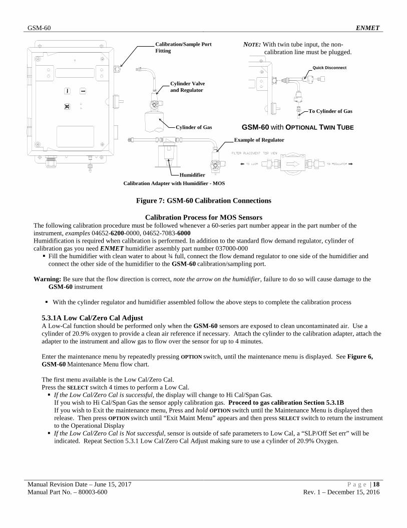
NOTE: With twin tube input, the non-calibration line must be plugged.
Figure 7: GSM-60 Calibration Connections
Calibration Process for MOS Sensors The following calibration procedure must be followed whenever a 60-series part number appear in the part number of the instrument, examples 04652-6200-0000, 04652-7083-6000 Humidification is required when calibration is performed. In addition to the standard flow demand regulator, cylinder of calibration gas you need ENMET humidifier assembly part number 037000-000 Fill the humidifier with clean water to about ¾ full, connect the flow demand regulator to one side of the humidifier and
connect the other side of the humidifier to the GSM-60 calibration/sampling port.
Warning: Be sure that the flow direction is correct, note the arrow on the humidifier, failure to do so will cause damage to the GSM-60 instrument
With the cylinder regulator and humidifier assembled follow the above steps to complete the calibration process
5.3.1A Low Cal/Zero Cal Adjust A Low-Cal function should be performed only when the GSM-60 sensors are exposed to clean uncontaminated air. Use a cylinder of 20.9% oxygen to provide a clean air reference if necessary. Attach the cylinder to the calibration adapter, attach the adapter to the instrument and allow gas to flow over the sensor for up to 4 minutes. Enter the maintenance menu by repeatedly pressing OPTION switch, until the maintenance menu is displayed. See Figure 6, GSM-60 Maintenance Menu flow chart. The first menu available is the Low Cal/Zero Cal. Press the SELECT switch 4 times to perform a Low Cal. If the Low Cal/Zero Cal is successful, the display will change to Hi Cal/Span Gas.
If you wish to Hi Cal/Span Gas the sensor apply calibration gas. Proceed to gas calibration Section 5.3.1B If you wish to Exit the maintenance menu, Press and hold OPTION switch until the Maintenance Menu is displayed then release. Then press OPTION switch until “Exit Maint Menu” appears and then press SELECT switch to return the instrument to the Operational Display
If the Low Cal/Zero Cal is Not successful, sensor is outside of safe parameters to Low Cal, a “SLP/Off Set err” will be indicated. Repeat Section 5.3.1 Low Cal/Zero Cal Adjust making sure to use a cylinder of 20.9% Oxygen.
Calibration/Sample Port Fitting
Cylinder of Gas
Cylinder Valve and Regulator
Example of Regulator
Humidifier
GSM-60 with OPTIONAL TWIN TUBE
To Cylinder of Gas
Quick Disconnect
Calibration Adapter with Humidifier - MOS

GSM-60 ENMET
Manual Revision Date – June 15, 2017 P a g e | 19 Manual Part No. – 80003-600 Rev. 1 – December 15, 2016
5.3.1B High Cal/Span Gas Adjust A High Cal/Span Gas should only be performed after a successful Low Cal/Zero Cal has been completed. Press the SELECT switch, that moves the cursor one digit to the right when the last digit is accepted the display will move to
"HI Cal xx" gas calibration. xx = the level of gas to be used for calibration. The mV reading is shown in the upper right hand corner of the display.
Apply calibration gas to sensor. See Figure 7. After about 1 minute and mV reading has stabilized. Press the SELECT switch, that moves the cursor one digit to the right, when the last digit is accepted and the calibration is
successful the display will momentarily show Cal OK then slope and off set readings, before returning to the Calibration Menu
Repeat above steps for each channel to be calibrated. To continue to next section, Press the OPTION switch. Press OPTION switch until “Exit Maint Menu” appears and then press SELECT switch to return the instrument to the
Operational Display
5.3.2 Set 4 –20mA Transmitter Scale This section of the maintenance menu is installed when there are 4-20mA style sensors for dew point or other gases. This function is normally performed at the factory and is not usually required to be performed in the field unless a new transmitter is installed. After entering a valid password into maintenance menu, the Scale mA Xmtrs section is the second menu section, if it is installed, enter by pressing the SELECT switch Press the SELECT switch "mA Xmter Scale: Select XX" is displayed. XX = the gas to be set up. Press the OPTION switch, if needed, to change to the gas to be set up. Press the SELECT switch, “Ch#: mAXmter: 4mA: 0000” is displayed Press the SELECT switch, that moves the cursor one digit to the right when the last digit is accepted the display move to the
full-Scale mA Xmtrs menu Press the SELECT switch, “Ch#: mAXmter: 20mA: 0000” is displayed Press the SELECT switch, that moves the cursor one digit to the right when the last digit is accepted the display will return to
the Scale mA Xmtrs menu Repeat these steps for each 4 –20mA transmitter. Press OPTION switch until “Exit Maint Menu” appears and then press SELECT switch to return the instrument to the
Operational Display Example: Sensor/Transmitter Set Up Flow Chart
O S
S mA Xmtr Scale
Select (Gas)
MAINTENANCE MENU
Scale mA Xmtrs
O Press OPTION until the gas to be Set Up is displayed
CH#: XX mA Xmter 4mA: 0000
S each digit CH#: XX mA Xmter
20mA: 0000 S each digit
O = Press Option S = Press Select

GSM-60 ENMET
Manual Revision Date – June 15, 2017 P a g e | 20 Manual Part No. – 80003-600 Rev. 1 – December 15, 2016
5.3.3 Set Alarm Points Factory alarm set points are discussed in Section 4.2, See Table 1. To change the alarm points, you must enter the maintenance menu. Entrance to the maintenance menu is guarded with a four-digit Password. The factory default setting of the password is 1270. When a valid numerical password is inserted, the user can enter the maintenance menu. In the "Enter Maint Menu" position Press the SELECT switch "Enter Password ζ 0" is displayed. Press SELECT switch once, to move cursor to next digit, this
will be the first digit of the password. In the ζ000 position, the underline cursor is under the left digit. Press the OPTION switch to change the left digit; select the correct digit. Press the SELECT switch, which locks the digit in place and moves the cursor one digit to the right. Continue this process until the four-digit password is complete. When a valid password is inserted in this manner, the display is transferred to the "Calibration" portion of the menu. If an invalid password is inserted, you are returned to the Enter Maint Menu display. After entering a valid password: Press the OPTION switch until; “Maintenance Menu Set Alarm1” appears on display. Press the SELECT switch, "ALARM1 Select: XX" is displayed. XX = the gas of alarm point to be changed. Press the OPTION switch until, desired gas is displayed. Press the SELECT switch; "ALARM 1 V " is displayed, with the flashing placeholder underscore cursor, under the left most
character, Λ for ascending trigger point or V for descending trigger point indicator. Press the OPTION switch to toggle between Λ and V; select the correct indicator. Press the SELECT switch to lock in the correct indicator. "ALARM 1 STD" is displayed Press the OPTION switch to toggle between STD and DIFF; select the correct indicator. Press the SELECT switch to lock in the correct indicator.
If STD is selected, "ALARM 1 V L " is displayed. The next character is the latching indicator L or NOL press the OPTION switch to toggle the latching mode. The next character is the negative sign – press the OPTION switch to toggle the negative sign. The next characters are the alarm 1 value, press the OPTION switch to select each digit of the value When the last digit is accepted display returns to the "Set Alarm1" position.
If DIFF is selected, "ALARM 1 DIFF Λ 000" is displayed. The next characters are the alarm 1 value, press the OPTION switch to select each digit of the value Press the SELECT switch to lock in the correct character and move the cursor to the right. "ALARM 1 DIFF BAND 000" is displayed, press the OPTION switch to select each digit of the value. The next characters are the alarm 1 differential value, press the OPTION switch to select each digit of the value Press the SELECT switch to lock in the correct character and move the cursor to the right. When the last digit is accepted, display returns to the "Set Alarm1" position.
Note: The Alarm 1 differential value is the delay of the GSM-60 staying in alarm condition until after the measured reading has returned past the alarm point by the differential value.
Example: If the alarm set point is Λ 10 and the differential is 2, the GSM-60 will go into alarm at 10 and stay in alarm until the
reading has dropped below 8. Repeat for each sensor alarm 1 to be changed. Press the OPTION switch to move to alarm 2, "Set ALARM2" is displayed. Repeat as for alarm 1 using the STD section. Press OPTION switch until “Exit Maint Menu” appears, then press SELECT switch to return the instrument to the Operational
Display

GSM-60 ENMET
Manual Revision Date – June 15, 2017 P a g e | 21 Manual Part No. – 80003-600 Rev. 1 – December 15, 2016
Example: Set Alarms Flow Chart Displays are examples of Alarms
Λ - Indicates alarm triggered on increasing value of reading v - Indicates alarm triggered on decreasing value of reading L- Indicates alarm is set for latching NOL- Indicates alarm is set for non-latching STD – Indicates alarm in standard setting, can be set in latched or non-latched mode DIFF – Indicates alarm in differential setting, instrument will stay in alarm beyond the alarm set point by the differential value
See Section 4.2 Table 3 for factory alarm set points.
S O
S O
S Alarm 2 - Select: XX
MAINTENANCE MENU
Set Alarm2
Changes character indicated by underscore cursor Locks underscored character and moves cursor to next
O Press OPTION until the channel to be Set is displayed
Alarm 2 V L 0000
O = Press Option S = Press Select
O S
S MAINTENANCE MENU
Set Alarm1
Alarm 1 - Select: XX
O Press OPTION until the channel to be Set is displayed
STD Alarm 1 O
S Toggles status between Standard and DIFF Locks selection
STD S
Alarm 1 DIFF BAND 000
Λ L–010 Alarm 1 O
S
Changes character indicated by underscore cursor Locks underscored character and moves cursor to next digit
DIFF S
O
S
Changes character indicated by underscore cursor
Locks underscored character and moves cursor to next digit
Λ Alarm 1 O
S Toggles status between Λ increasing trigger and v decreasing trigger Locks selection
S
Λ ζL Alarm 1 O
S
Toggles status between Latching and Non Latching Locks selection
Alarm 1 Λ DIFF 000
O S
Changes character indicated by underscore cursor
Locks underscored character and moves cursor to next digit

GSM-60 ENMET
Manual Revision Date – June 15, 2017 P a g e | 22 Manual Part No. – 80003-600 Rev. 1 – December 15, 2016
5.3.4 Set Alarm Delay The alarms may be set to delay by 1 second increments, up to 255 seconds. Alarm delays are factory set to 5 seconds. To change an alarm delay, you must enter the maintenance menu. Press the OPTION switch until “Enter Maint Menu” is displayed then press SELECT switch for the Enter Password menu. Enter the valid password as described in Section 5.2.1. See Table 4 below for factory set delays. A space is provided to record changes. After entering a valid password: Press the OPTION switch until; “Maintenance Menu Set Alarm Delay” appears on display. Press the SELECT switch, "ALARM Delay Select: XX" is displayed. XX = the gas alarm to be changed. Press the OPTION switch until, desired gas is displayed. Press the SELECT switch; "ALARM Delay = 0000" is displayed, with the underscore cursor under the left digit. Press the OPTION switch to change the left digit; select the correct digit. Press the SELECT switch to lock in the correct digit and move the cursor one digit to the right. When the last digit is
accepted, display returns to the "Set Alarm Delay" position. Repeat for each sensor alarm delay to be changed. Press OPTION switch until “Exit Maint Menu” appears and then press SELECT switch to return the instrument to the
Operational Display
Example: Set Alarm Delay Flow Chart
Table 4: Factory Set Gas alarms Delay
Gas Delay CO 5 sec H2S 5 sec O2 5 sec CO2 5 sec
O
S MAINTENANCE MENU
Set Alarm Delays
S O
S
Alarm Delay -
Changes digit indicated by underscore cursor Locks underscored digit and moves cursor to next digit
O Press Option until the channel to be Set is displayed Select: XX
Alarm Delay - 0005
O = Press Option S = Press Select

GSM-60 ENMET
Manual Revision Date – June 15, 2017 P a g e | 23 Manual Part No. – 80003-600 Rev. 1 – December 15, 2016
5.3.5 Relay Configuration To change a relay configuration, you must enter the maintenance menu. Press the OPTION switch until “Enter Maint Menu” is displayed then press SELECT switch for the Enter Password menu. Enter the valid password as described below. In the "Enter Maint Menu" position Press the SELECT switch "Enter Password ζ 0" is displayed. Press SELECT switch once, to move cursor to next digit,
this will be the first digit of the password. In the ζ000 position, the underline cursor is under the left digit. Press the OPTION switch to change the left digit; select the correct digit. Press the SELECT switch, which locks the digit in place and moves the cursor one digit to the right.
Continue this process until the four-digit password is complete. When a valid password is inserted in this manner, the display is transferred to the "Calibration" portion of the menu. If an invalid password is inserted, you are returned to the Enter Maint Menu display.
After entering a valid password: Press the OPTION switch until “Configure Alarms” is displayed Press the SELECT switch to enter the Configure Alarms menu Press the OPTION switch to set relay configuration as needed, see below for indications
L = Low Alarm, H = High Alarm, B = Both Alarms, ζ = No Relay linked to channel Press the SELECT switch to lock setting and move to next, channel and relay Press OPTION switch until “Exit Maint Menu” appears and then press SELECT switch to return the instrument to the
Operational Display
Example: Set Relay Configuration Flow Chart
The table below shows the default relay links. Channel 1 Channel 2 Channel 3 Channel 4
Relay 1 Low Alarm Relay 2 Low Alarm Relay 3 Low Alarm Relay 4 Low Alarm Relay 5 High Alarm High Alarm High Alarm High Alarm
Relays can be linked to specific alarms. NOTE: Each operating channel must be linked to at least 1 relay.
O
SMAINTENANCE MENU
Configure Alarms
Ch 1,2,3,4R1 L
Pressing OPTION changes letter indicated by underscore cursorPressing SELECT Locks underscored digit and moves cursor to next digit
Ch 1 2 3 4R2 L
Ch 1 2 3 4R3 L
Ch 1 2 3 4R4 L
Ch 1 2 3 4R5 H H H H
O = Press Option S = Press Select

GSM-60 ENMET
Manual Revision Date – June 15, 2017 P a g e | 24 Manual Part No. – 80003-600 Rev. 1 – December 15, 2016
5.3.6 Failsafe Configuration To change a relay failsafe configuration, you must enter the maintenance menu. Press the OPTION switch until “Enter Maint Menu” is displayed then press SELECT switch for the Enter Password menu. Enter the valid password as described below. In the "Enter Maint Menu" position Press the SELECT switch "Enter Password ζ 0" is displayed. Press SELECT switch once, to move cursor to next digit, this
will be the first digit of the password. In the ζ000 position, the underline cursor is under the left digit. Press the OPTION switch to change the left digit; select the correct digit. Press the switch, which locks the digit in place and moves the cursor one digit to the right.
Continue this process until the four-digit password is complete. When a valid password is inserted in this manner, the display is transferred to the "Calibration" portion of the menu. If an invalid password is inserted, you are returned to the Enter Maint Menu display.
After entering a valid password: Press the OPTION switch until “Relay Failsafes” is displayed Press the SELECT switch to indicate relay to be set. Press the OPTION switch to set relay indicated, On or Off as appropriate. Press the SELECT switch to cycle through each of the 5 relays, return to “Maintenance Menu Relay Failsafes” Press OPTION switch until “Exit Maint Menu” appears and then press SELECT switch to return the instrument to the
Operational Display
Example: Set Relay Failsafe Configuration Flow Chart
5.3.7 Set Output Span Range To change 4-20 mA output range. This range is set at the factory and should not be changed, contact ENMET for information. Press the OPTION switch to continue to next section of maintenance menu. Press OPTION switch until “Exit Maint Menu” appears and then press SELECT switch to return the instrument to the
Operational Display Example: Set Output Span Flow Chart
O = Press Option S = Press Select
O
S MAINTENANCE MENU
mA Output Span
S O
S
mA OUTPUT SPAN
Changes digit indicated by underscore cursor Locks underscored digit and moves cursor to next digit
O Press OPTION until the channel to be Set is displayed. Select: CO
mA OUTPUT SPAN _ 50 CO
S
O = Press Option S = Press Select
O
S MAINTENANCE MENU
Relay Failsafes
S
Continue pressing SELECT to cycle through all 5 relays Changing the setting of each relay as needed, using the Option switch
Pressing OPTION changes Failsafe setting from ON to OFF Relay Failsafes R: 1 Failsafe ON
Relay Failsafes R: 2 Failsafe ON
Relay Failsafes R: 3 Failsafe ON
Relay Failsafes R: 4 Failsafe ON
Relay Failsafes R: 5 Failsafe ON

GSM-60 ENMET
Manual Revision Date – June 15, 2017 P a g e | 25 Manual Part No. – 80003-600 Rev. 1 – December 15, 2016
5.3.8 Set New Password To change the password, you must enter the maintenance menu. Press the OPTION switch until “Enter Maint Menu” is displayed then press SELECT switch for the Enter Password menu. Enter the valid password as described in Section 5.2.1. To set a new password, after inserting a valid password, Press the OPTION switch until; "Set New Password” is displayed. Press the SELECT switch; "Password ζ1270" is displayed, with the underscore cursor under the left digit. Use the OPTION switch to change the left digit, when the desired digit is displayed. Press the SELECT switch to lock the digit in place and move the cursor one digit to the right.
When all four digits of the new password have been selected, "Set New Password" is displayed. Record the new password; without it, the maintenance menu cannot be reentered once you exit the Maintenance Menu. If the password is lost, call ENMET customer service personnel. From the "Password XXXX" position, Press the SELECT switch to return to Set New Password section. Press the OPTION switch; to continue to "exit MAINTENANCE Menu"
Example: Set Password Flow Chart
5.3.9 Exit Maintenance Menu From the "exit MAINTENANCE Menu" position Press the SELECT switch to resume the operational display. Press the OPTION switch to reenter the maintenance menu at the "Calibration" position.
Example: Exit Maintenance Menu Flow Chart
O
S MAINTENANCE MENU
Set New Password Password 0000
O S
Changes digit indicated by underscore cursor Locks underscored digit and moves cursor to next digit
MAINTENANCE MENU Ca l ib r a t ion
MAINTENANCE MENU Exit Maint Menu
CH-1 CH-3 CH-2 CH-4
S O
O = Press Option S = Press Select

GSM-60 ENMET
Manual Revision Date – June 15, 2017 P a g e | 26 Manual Part No. – 80003-600 Rev. 1 – December 15, 2016
5.4 Sensor Replacement 5.4.1 Gas/Oxygen Sensor A Gas sensor must be replaced when it can no longer be calibrated. To replace a sensor, perform the following steps. Turn off the electrical power. The sample air can continue to flow. Open the display panel and remove the four manifold retention screws and remove the manifold. See Figure 9. Remove the old sensor, and replace it with a new sensor. It is recommended that the sensor gasket/manifold also be
checked and potentially replaced at the time the sensor is replaced. CAUTION: Some new sensors come with a shorting clip that must be removed before installation, for proper operation. See
Figure 8.
Replace the manifold. Turn on the electrical power.
Figure 9: Location of Gas Sensor and PiD (HC) Manifolds
5.4.2 Calibration/Sensor Replacement Sensor replacement requires that a Factory Calibration be performed. Factory Calibration allows the instrument to properly set operational parameters for each sensor. Calibration is the process of setting the instrument up to read accurately when exposed to a target gas. This is a two-step process. A Low Calibration sets clean air reference point and the High Calibration function sets the sensitivity of the instrument. Calibration equipment is available from ENMET to calibrate the GSM-60. A list of needed material is in Section 7.0. A calibration adapter will have a fitting for the gas cylinder on one side, and a quick-disconnect to attach to the instrument on the other. You may exit the calibration section, at any time, by pressing and holding the OPTION switch for 3 seconds, if entering calibration section by mistake or calibration gas is not available. Wait 24 hours after initially supplying air and power to the GSM-60 sensor before initial calibration. It is not necessary to open the Front Panel to make adjustment. The calibration functions are operated through the OPTION and SELECT switches on the front panel.
PiD (HC) Sensor Manifold
Gas Sensor Manifold Retaining Screw, 4 places
Remove Shorting Clip from Cell if Present
Bottom View of Sensor
Figure 8: Shorting Clip
To Pump Orifice

GSM-60 ENMET
Manual Revision Date – June 15, 2017 P a g e | 27 Manual Part No. – 80003-600 Rev. 1 – December 15, 2016
After entering a valid password to maintenance menu, see Section 5.2.1, the calibration section is the first menu section; enter by pressing the SELECT switch. Supply sensor with clean air for Low Cal/Zero Cal setting and apply calibration gas for Hi Cal/Span Gas setting. Press the SELECT switch "Calibration Select XX" is displayed. XX = the gas to be calibrated Press and Hold the OPTION switch, until the letter F appears in the upper right hand corner of the display. The F indicates
that the instrument is in the Factory Calibration Mode. Press the OPTION switch, if needed, to change to the gas to be calibrated. Press the SELECT switch, the gas & current reading is displayed in upper portion of display. The mV reading & "Low Cal
0" is displayed in the lower portion of display. This is the Low Cal setting, usually zero, clean air must be supplied to the sensor. This reading needs to be at or near zero. If it is not, then a cylinder of clean 20.9 air should be used. See Figure 7 if this is required.
Press the SELECT switch, that moves the cursor one digit to the right when the last digit is accepted the display will move to "Hi Cal xx" gas calibration. xx = the level of gas to be used for calibration. The mV reading is shown in the upper right hand corner of the display.
Apply calibration gas to sensor. See Figure 7. After about 1 minute and mV reading has stabilized. Press the SELECT switch, that moves the cursor one digit to the right, when the last digit is accepted and the calibration is
successful the display will momentarily show Cal OK then slope and off set readings, before returning to the Calibration Menu
Repeat above steps for each channel to be calibrated.
NOTE: Instruments equipped with an oxygen sensor programmed with a range of 0 to 15% by volume require 99.999 % Nitrogen (ENMET part number 03295-100) be used for the Low Cal/Zero Cal setting and 5% by volume Oxygen (ENMET part number 03296-050) be used for HI Cal/Span setting
To continue to next section, Press the OPTION switch. Press OPTION switch until “Exit Maint Menu” appears and then press SELECT switch to return the instrument to the
Operational Display
Example: Full Calibration Flow Chart, for CO From Valid Password Entry
Default Calibration Points Gas Low Cal Hi Cal
CO 0 20
O2 N/A* 20.9*
CO2 0 1000
HC 0 10
O = Press Option S = Press Select
O S
S Calibration
Select (Gas)
MAINTENANCE MENU
Calibration
O Press OPTION until the gas to beCalibrated is displayed
CO: XX 11
LowCal: 0000S each digit
CO: XX 14
HiCal: 0000S each digit

GSM-60 ENMET
Manual Revision Date – June 15, 2017 P a g e | 28 Manual Part No. – 80003-600 Rev. 1 – December 15, 2016
NOTE: With twin tube input, the non-calibration line must be plugged.
Figure 7: GSM-60 Calibration Connections
Calibration Process for MOS Sensors The following calibration procedure must be followed whenever a 60-series part number appear in the part number of the instrument, examples 04652-6200-0000, 04652-7083-6000 Humidification is required when calibration is performed. In addition to the standard flow demand regulator, cylinder of calibration gas you need ENMET humidifier assembly part number 037000-000 Fill the humidifier with clean water to about ¾ full, connect the flow demand regulator to one side of the humidifier and
connect the other side of the humidifier to the GSM-60 calibration/sampling port.
Warning: Be sure that the flow direction is correct, note the arrow on the humidifier, failure to do so will cause damage to the GSM-60 instrument
With the cylinder regulator and humidifier assembled follow the above steps to complete the calibration process 5.4.3A Low Cal/Zero Cal Adjust A Low Cal function should be performed only when the GSM-60 sensors are exposed to clean uncontaminated air. Use a cylinder of 20.9% oxygen to provide a clean air reference if necessary. Attach the cylinder to the calibration adapter, attach the adapter to the instrument and allow gas to flow over the sensor for up to 4 minutes. Enter the maintenance menu by repeatedly pressing OPTION switch, until the maintenance menu is displayed. See Figure 6, GSM-60 Maintenance Menu flow chart. The first menu available is the Low Cal/Zero Cal. Press the SELECT switch 4 times to perform a Low Cal. If the Low Cal/Zero Cal is successful, the display will change to Hi Cal/Span Gas.
If you wish to Hi Cal/Span Gas the sensor apply calibration gas. Proceed to gas calibration Section 5.3.1B If you wish to Exit the maintenance menu, Press and hold OPTION switch until the Maintenance Menu is displayed then release. Then press OPTION switch until “Exit Maint Menu” appears and then press SELECT switch to return the instrument to the Operational Display
If the Low Cal/Zero Cal is Not successful, sensor is outside of safe parameters to Low Cal, a “SLP/Off Set err” will be indicated. Repeat Section 5.3.1 Low Cal/Zero Cal Adjust making sure to use a cylinder of 20.9% Oxygen.
Cylinder of Gas
Cylinder Valve and Regulator
Calibration/Sample Port Fitting
GSM-60 with OPTIONAL TWIN TUBE
To Cylinder of Gas
Quick Disconnect 2 places
Plug
Example of Regulator
Humidifier Calibration Adapter with Humidifier - MOS

GSM-60 ENMET
Manual Revision Date – June 15, 2017 P a g e | 29 Manual Part No. – 80003-600 Rev. 1 – December 15, 2016
5.4.3B High Cal/Span Gas Adjust A High Cal/Span Gas should only be performed after a successful Low Cal/Zero Cal has been completed. Press the SELECT switch, that moves the cursor one digit to the right when the last digit is accepted the display will move to
"Hi Cal xx" gas calibration. xx = the level of gas to be used for calibration. The mV reading is shown in the upper right hand corner of the display.
Apply calibration gas to sensor. See Figure 7. After about 1 minute and mV reading has stabilized. Press the SELECT switch, that moves the cursor one digit to the right, when the last digit is accepted and the calibration is
successful the display will momentarily show Cal OK then slope and off set readings, before returning to the Calibration Menu
Repeat above steps for each channel to be calibrated. To continue to next section, Press the OPTION switch. Press OPTION switch until “Exit Maint Menu” appears and then press SELECT switch to return the instrument to the
Operational Display
5.5 Flow Control Orifice A 0.0225-inch diameter orifice is used to set the flow rate. In well-maintained medical air systems, this orifice should not clog. However, if difficulty is experienced in maintaining flow rate examine this orifice; replace it if necessary. Orifice location will depend on instrument sensor configuration.
6.0 Technical Data and Specifications NOTE: All specifications stated in this manual may change without notice.
Electrical Power 15 Amp fused branch circuit 100-240 VAC 0.9 A 50/60 Hz Board Mounted Fuse FH2, 0.630A, 5 x 20mm
Storage and Transport
Temperature: -20° to +60°C (-4° to +140°F) preferred 0° to +20°C (32° to 68°F) Relative Humidity 0 - 99% RH, non-condensing Atmospheric Pressure 20 to 36 inHg (68 to 133 kPa)
Operation Temperature: 0° to +40°C (32° to +104°F) Relative Humidity 0 - 99% RH, non-condensing Atmospheric Pressure 20 to 36 inHg (68 to 133 kPa)
Mechanical Dimensions: 11 x 9 x 8 inches (27.9 x 22.9 x 20.3 cm) Weight: 8 lbs (3.6 kg) Material: Engineered thermoplastic with hinged front cover Strain relief: 5 – 12 mm OD
Outputs Relays: SPDT Resistive Load Inductive Load 10A at 110 VAC 7.5A at 110 VAC 10A at 30 VDC 5A at 30 VDC
Analog: 4-20 mA x 3
Digital: RS-232 – Modbus RS-485 – Modbus
Audio: 95 db at 2 ft Examples of Sensors Type Range *Typical Response Time Life CO 0 – 50 ppm T90 = 30 seconds 1 – 3 years O2 0 – 30% T90 = 15 seconds 1 – 2 years CO2 0 – 5000 ppm T90 = 30 seconds 3 – 5 years HC 0 – 100 ppm T90 = 30 seconds 1 – 2 years Others Contact ENMET
NOTE: Response time is dependent on sampling length.

GSM-60 ENMET
Manual Revision Date – June 15, 2017 P a g e | 30 Manual Part No. – 80003-600 Rev. 1 – December 15, 2016
7.0 Replacement Part Numbers 7.1 ENMET part numbers for sensors and replacement parts:
Part number Description 03053-000 Sensor, CO2 67025-1114 Sensor, Oxygen 03015-014 Sensor, MOS 812 03016-014 Sensor, MOS 813 03028-XXX Sensor, PID, 10.6 eV
Contact ENMET 67025-XXXX Sensor, Toxic
Contact ENMET 03028-005 Sensor, Replacement lamp, PID, 10.6 eV 73540-002 Orifice 64002-1000 Fuse, 1.0 Amp 5x20mm 06008-004 Sensor Gasket 65057-011 Terminal plug, 3 position 65057-012 Terminal plug, 4 position 65057-010 Terminal plug, 2 position 73089-004 Filter Assembly, Particulate 04018-128 Pump, Replacement for instrument s/n 118 and above 04018-118 Pump, Replacement for instrument s/n 117 and below
Consult ENMET or your distributer for more information
7.2 ENMET part numbers for Calibration equipment: Part number Description 03219-020 Gas Cylinder, 20 ppm CO in air 03296-209 Gas Cylinder, 20.9% oxygen in nitrogen 03510-001 Regulator Assembly, Flow Demand CO, O2 (steel cylinders) 03223-1000 Gas Cylinder, 1000 ppm CO2 in air, 03510-002 Regulator Assembly, Flow Demand CO2 (aluminum cylinders) 03290-010 Gas Cylinder, 10 ppm Isobutylene in air
Consult ENMET or your distributer for more information

GSM-60 ENMET
Manual Revision Date – June 15, 2017 P a g e | 31 Manual Part No. – 80003-600 Rev. 1 – December 15, 2016
Appendix A: CO Characteristics The Characteristics and Effects of Carbon Monoxide Carbon monoxide is a colorless odorless toxic gas generated by incomplete combustion of a hydrocarbon fuel in air. It may be present where internal combustion engines, furnaces, boilers, and other combustion devices are present. It is toxic when inhaled because of its great affinity to hemoglobin, the oxygen carriers in the red cells of the blood. CO replaces the oxygen normally carried by the hemoglobin, and thus inhibits the delivery of oxygen throughout the body; the victim suffers from oxygen deficiency, and may die from asphyxiation. The symptoms and degree of danger resulting from exposure to CO depend upon the concentration of the gas and the length of exposure; this is shown in Figure 10. The GSM-60 instrument is employed to warn the user of the presence of CO, and to facilitate the assessment of the degree of danger that he or she is exposed to. Based upon knowledge of the effects of CO, the Occupational Safety and Health Authority (OSHA) has set limits on exposure to CO in the workplace. These are 35 ppm (parts CO per million parts air) as a time weighted average for an eight-hour day, and a maximum exposure of 200 ppm. For compressed air line applications, OSHA requires Grade D breathing air supplied, using a Compressed Gas Association (CGA) definition (G-7.1). Depending on interpretation of the OSHA respiratory standard, 10 ppm and 20 ppm CO have been used as maximum limits and standard instrument alarm points. If a CO sensor is installed, the GSM-60 has two preset alarm set points, at 10 ppm and 20 ppm CO, which are adjustable, but cannot be set below 5 ppm or above 50 ppm. The curves below are for percent Carboxyhemoglobin with 50% being the top curve, 5% the bottom. %COHb is a measure of the amount of hemoglobin occupied by CO rather than oxygen. CO effects upon children, adults engaging in physical activity, and smokers, are more pronounced.
Figure 10: Carbon Monoxide Concentration

GSM-60 ENMET
Manual Revision Date – June 15, 2017 P a g e | 32 Manual Part No. – 80003-600 Rev. 1 – December 15, 2016
Appendix B: Gas Ionization Potentials
Chemical Name IP (eV) Chemical Name IP (eV) A p-Bromotoluene 8.67
2-Amino pyridine 8.00 p-tert-Butyltoluene 8.28 Acetaldehyde 10.21 s-Butyl amine 8.70 Acetamide 9.77 s-Butyl benzene 8.68 Acetic acid 10.69 sec-Butyl acetate 9.91 Acetic anhydride 10.00 t-Butyl amine 8.64 Acetone 9.69 t-Butyl benzene 8.68 Acetonitrile 12.20 trans-2-Butene 9.13 Acetophenone 9.27 C
Acetyl bromide 10.55 1-Chloro-2-methylpropane 10.66 Acetyl chloride 11.02 1-Chloro-3-fluorobenzene 9.21 Acetylene 11.41 1-Chlorobutane 10.67 Acrolein 10.10 1-Chloropropane 10.82 Acrylamide 9.50 2-Chloro-2-methylpropane 10.61 Acrylonitrile 10.91 2-Chlorobutane 10.65 Allyl alcohol 9.67 2-Chloropropane 10.78 Allyl chloride 9.90 2-Chlorothiophene 8.68 Ammonia 10.20 3-Chloropropene 10.04 Aniline 7.70 Camphor 8.76 Anisidine 7.44 Carbon dioxide 13.79 Anisole 8.22 Carbon disulfide 10.07 Arsine 9.89 Carbon monoxide 14.01 B Carbon tetrachloride 11.47
1,3-Butadiene (butadiene) 9.07 Chlorine 11.48 1-Bromo-2-chloroethane 10.63 Chlorine dioxide 10.36 1-Bromo-2-methylpropane 10.09 Chlorine trifluoride 12.65 1-Bromo-4-fluorobenzene 8.99 Chloroacetaldehyde 10.61 1-Bromobutane 10.13 α-Chloroacetophenone 9.44 1-Bromopentane 10.10 Chlorobenzene 9.07 1-Bromopropane 10.18 Chlorobromomethane 10.77 1-Bromopropene 9.30 Chlorofluoromethane (Freon 22) 12.45 1-Butanethiol 9.14 Chloroform 11.37 1-Butene 9.58 Chlorotrifluoromethane (Freon 13) 12.91 1-Butyne 10.18 Chrysene 7.59 2,3-Butadione 9.23 Cresol 8.14 2-Bromo-2-methylpropane 9.89 Crotonaldehyde 9.73 2-Bromobutane 9.98 Cumene (isopropyl benzene) 8.75 2-Bromopropane 10.08 Cyanogen 13.80 2-Bromothiophene 8.63 Cyclohexane 9.80 2-Butanone (MEK) 9.54 Cyclohexanol 9.75 3-Bromopropene 9.70 Cyclohexanone 9.14 3-Butene nitrile 10.39 Cyclohexene 8.95 Benzaldehyde 9.53 Cyclo-octatetraene 7.99 Benzene 9.25 Cyclopentadiene 8.56 Benzenethiol 8.33 Cyclopentane 10.53 Benzonitrile 9.71 Cyclopentanone 9.26 Benzotrifluoride 9.68 Cyclopentene 9.01 Biphenyl 8.27 Cyclopropane 10.06 Boron oxide 13.50 m-Chlorotoluene 8.83 Boron trifluoride 15.56 o-Chlorotoluene 8.83 Bromine 10.54 p-Chlorotoluene 8.70 Bromobenzene 8.98 D
Bromochloromethane 10.77 1,1-Dibromoethane 10.19 Bromoform 10.48 1,1-Dichloroethane 11.12 Butane 10.63 1,1-Dimethoxyethane 9.65 Butyl mercaptan 9.15 1,1-Dimethylhydrazine 7.28 cis-2-Butene 9.13 1,2-Dibromoethene 9.45 m-Bromotoluene 8.81 1,2-Dichloro-1,1,2,2-tetrafluoroethane (Freon 114) 12.20 n-Butyl acetate 10.01 1,2-Dichloroethane 11.12 n-Butyl alcohol 10.04 1,2-Dichloropropane 10.87 n-Butyl amine 8.71 1,3-Dibromopropane 10.07 n-Butyl benzene 8.69 1,3-Dichloropropane 10.85 n-Butyl formate 10.50 2,2-Dimethyl butane 10.06 n-Butyraldehyde 9.86 2,2-Dimethyl propane 10.35 n-Butyric acid 10.16 2,3-Dichloropropene 9.82 n-Butyronitrile 11.67 2,3-Dimethyl butane 10.02 o-Bromotoluene 8.79 3,3-Dimethyl butanone 9.17 cis-Dichloroethene 9.65
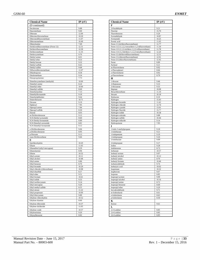
GSM-60 ENMET
Manual Revision Date – June 15, 2017 P a g e | 33 Manual Part No. – 80003-600 Rev. 1 – December 15, 2016
Chemical Name IP (eV) Chemical Name IP (eV) (D continued) F
Decaborane 9.88 2-Furaldehyde 9.21 Diazomethane 9.00 Fluorine 15.70 Diborane 12.00 Fluorobenzene 9.20 Dibromochloromethane 10.59 Formaldehyde 10.87 Dibromodifluoromethane 11.07 Formamide 10.25 Dibromomethane 10.49 Formic acid 11.05 Dibutylamine 7.69 Freon 11 (trichlorofluoromethane) 11.77 Dichlorodifluoromethane (Freon 12) 12.31 Freon 112 (1,1,2,2-tetrachloro-1,2-difluoroethane) 11.30 Dichlorofluoromethane 12.39 Freon 113 (1,1,2-trichloro-1,2,2-trifluororethane) 11.78 Dichloromethane 11.35 Freon 114 (1,2-dichloro-1,1,2,2-tetrafluoroethane) 12.20 Diethoxymethane 9.70 Freon 12 (dichlorodifluoromethane) 12.31 Diethyl amine 8.01 Freon 13 (chlorotrifluoromethane) 12.91 Diethyl ether 9.53 Freon 22 (chlorofluoromethane) 12.45 Diethyl ketone 9.32 Furan 8.89 Diethyl sulfide 8.43 Furfural 9.21 Diethyl sulfite 9.68 m-Fluorotoluene 8.92 Difluorodibromomethane 11.07 o-Fluorophenol 8.66 Dihydropyran 8.34 o-Fluorotoluene 8.92 Diiodomethane 9.34 p-Fluorotoluene 8.79 Diisopropylamine 7.73 H
Dimethoxymethane (methylal) 10.00 1-Hexene 9.46 Dimethyl amine 8.24 2-Heptanone 9.33 Dimethyl ether 10.00 2-Hexanone 9.35 Dimethyl sulfide 8.69 Heptane 10.08 Dimethylaniline 7.13 Hexachloroethane 11.10 Dimethylformamide 9.18 Hexane 10.18 Dimethylphthalate 9.64 Hydrazine 8.10 Dinitrobenzene 10.71 Hydrogen 15.43 Dioxane 9.19 Hydrogen bromide 11.62 Diphenyl 7.95 Hydrogen chloride 12.74 Dipropyl amine 7.84 Hydrogen cyanide 13.91 Dipropyl sulfide 8.30 Hydrogen fluoride 15.77 Durene 8.03 Hydrogen iodide 10.38 m-Dichlorobenzene 9.12 Hydrogen selenide 9.88 N,N-Diethyl acetamide 8.60 Hydrogen sulfide 10.46 N,N-Diethyl formamide 8.89 Hydrogen telluride 9.14 N,N-Dimethyl acetamide 8.81 Hydroquinone 7.95 N,N-Dimethyl formamide 9.12 I
o-Dichlorobenzene 9.06 1-Iodo-2-methylpropane 9.18 p-Dichlorobenzene 8.95 1-Iodobutane 9.21 p-Dioxane 9.13 1-Iodopentane 9.19 trans-Dichloroethene 9.66 1-Iodopropane 9.26 E 2-Iodobutane 9.09
Epichlorohydrin 10.20 2-Iodopropane 9.17 Ethane 11.65 Iodine 9.28 Ethanethiol (ethyl mercaptan) 9.29 Iodobenzene 8.73 Ethanolamine 8.96 Isobutane 10.57 Ethene 10.52 Isobutyl acetate 9.97 Ethyl acetate 10.11 Isobutyl alcohol 10.12 Ethyl alcohol 10.48 Isobutyl amine 8.70 Ethyl amine 8.86 Isobutyl formate 10.46 Ethyl benzene 8.76 Isobutyraldehyde 9.74 Ethyl bromide 10.29 Isobutyric acid 10.02 Ethyl chloride (chloroethane) 10.98 Isopentane 10.32 Ethyl disulfide 8.27 Isophorone 9.07 Ethyl ether 9.51 Isoprene 8.85 Ethyl formate 10.61 Isopropyl acetate 9.99 Ethyl iodide 9.33 Isopropyl alcohol 10.16 Ethyl isothiocyanate 9.14 Isopropyl amine 8.72 Ethyl mercaptan 9.29 Isopropyl benzene 8.69 Ethyl methyl sulfide 8.55 Isopropyl ether 9.20 Ethyl nitrate 11.22 Isovaleraldehyde 9.71 Ethyl propionate 10.00 m-Iodotoluene 8.61 Ethyl thiocyanate 9.89 o-Iodotoluene 8.62 Ethylene chlorohydrin 10.52 p-Iodotoluene 8.50 Ethylene diamine 8.60 K
Ethylene dibromide 10.37 Ketene 9.61 Ethylene dichloride 11.05 L
Ethylene oxide 10.57 2,3-Lutidine 8.85 Ethylenelmine 9.20 2,4-Lutidine 8.85 Ethynylbenzene 8.82 2,6-Lutidine 8.85

GSM-60 ENMET
Manual Revision Date – June 15, 2017 P a g e | 34 Manual Part No. – 80003-600 Rev. 1 – December 15, 2016
Chemical Name IP (eV) Chemical Name IP (eV) M (P continued)
2-Methyl furan 8.39 2-Pentanone 9.38 2-Methyl napthalene 7.96 2-Picoline 9.02 1-Methyl napthalene 7.96 3-Picoline 9.02 2-Methyl propene 9.23 4-Picoline 9.04 2-Methyl-1-butene 9.12 n-Propyl nitrate 11.07 2-Methylpentane 10.12 Pentaborane 10.40 3-Methyl-1-butene 9.51 Pentane 10.35 3-Methyl-2-butene 8.67 Perchloroethylene 9.32 3-Methylpentane 10.08 Pheneloic 8.18 4-Methylcyclohexene 8.91 Phenol 8.50 Maleic anhydride 10.80 Phenyl ether (diphenyl oxide) 8.82 Mesityl oxide 9.08 Phenyl hydrazine 7.64 Mesitylene 8.40 Phenyl isocyanate 8.77 Methane 12.98 Phenyl isothiocyanate 8.52 Methanethiol (methyl mercaptan) 9.44 Phenylene diamine 6.89 Methyl acetate 10.27 Phosgene 11.77 Methyl acetylene 10.37 Phosphine 9.87 Methyl acrylate 9.90 Phosphorus trichloride 9.91 Methyl alcohol 10.85 Phthalic anhydride 10.00 Methyl amine 8.97 Propane 11.07 Methyl bromide 10.54 Propargyl alcohol 10.51 Methyl butyl ketone 9.34 Propiolactone 9.70 Methyl butyrate 10.07 Propionaldehyde 9.98 Methyl cellosolve 9.60 Propionic acid 10.24 Methyl chloride 11.28 Propionitrile 11.84 Methyl chloroform (1,1,1-trichloroethane) 11.00 Propyl acetate 10.04 Methyl disulfide 8.46 Propyl alcohol 10.20 Methyl ethyl ketone 9.53 Propyl amine 8.78 Methyl formate 10.82 Propyl benzene 8.72 Methyl iodide 9.54 Propyl ether 9.27 Methyl isobutyl ketone 9.30 Propyl formate 10.54 Methyl isobutyrate 9.98 Propylene 9.73 Methyl isocyanate 10.67 Propylene dichloride 10.87 Methyl isopropyl ketone 9.32 Propylene imine 9.00 Methyl isothiocyanate 9.25 Propylene oxide 10.22 Methyl mercaptan 9.44 Propyne 10.36 Methyl methacrylate 9.70 Pyridine 9.32 Methyl propionate 10.15 Pyrrole 8.20 Methyl propyl ketone 9.39 Q
-Methyl styrene 8.35 Quinone 10.04 Methyl thiocyanate 10.07 S
Methylal (dimethoxymethane) 10.00 Stibine 9.51 Methylcyclohexane 9.85 Styrene 8.47 Methylene chloride 11.32 Sulfur dioxide 12.30 Methyl-n-amyl ketone 9.30 Sulfur hexafluoride 15.33 Monomethyl aniline 7.32 Sulfur monochloride 9.66 Monomethyl hydrazine 7.67 Sulfuryl fluoride 13.00 Morpholine 8.20 T
n-Methyl acetamide 8.90 o-Terphenyls 7.78 N 1,1,2,2-Tetrachloro-1,2-difluoroethane (Freon 112) 11.30
1-Nitropropane 10.88 1,1,1-Trichloroethane 11.00 2-Nitropropane 10.71 1,1,2-Trichloro-1,2,2-trifluoroethane (Freon 113) 11.78 Naphthalene 8.12 2,2,4-Trimethyl pentane 9.86 Nickel carbonyl 8.27 o-Toluidine 7.44 Nitric oxide, (NO) 9.25 Tetrachloroethane 11.62 Nitrobenzene 9.92 Tetrachloroethene 9.32 Nitroethane 10.88 Tetrachloromethane 11.47 Nitrogen 15.58 Tetrahydrofuran 9.54 Nitrogen dioxide 9.78 Tetrahydropyran 9.25 Nitrogen trifluoride 12.97 Thiolacetic acid 10.00 Nitromethane 11.08 Thiophene 8.86 Nitrotoluene 9.45 Toluene 8.82 p-Nitrochloro benzene 9.96 Tribromoethene 9.27 O Tribromofluoromethane 10.67
Octane 9.82 Tribromomethane 10.51 Oxygen 12.08 Trichloroethene 9.45 Ozone 12.08 Trichloroethylene 9.47 P Trichlorofluoromethane (Freon 11) 11.77
1-Pentene 9.50 Trichloromethane 11.42 1-Propanethiol 9.20 Triethylamine 7.50 2,4-Pentanedione 8.87 Trifluoromonobromo-methane 11.40

GSM-60 ENMET
Manual Revision Date – June 15, 2017 P a g e | 35 Manual Part No. – 80003-600 Rev. 1 – December 15, 2016
Chemical Name IP (eV) Chemical Name IP (eV) (T continued) W
Trimethyl amine 7.82 Water 12.59 Tripropyl amine 7.23 X
V 2,4-Xylidine 7.65
o-Vinyl toluene 8.20 m-Xylene 8.56 Valeraldehyde 9.82 o-Xylene 8.56 Valeric acid 10.12 p-Xylene 8.45 Vinyl acetate 9.19 Vinyl bromide 9.80 Vinyl chloride 10.00 Vinyl methyl ether 8.93
Notes:

GSM-60 ENMET
Manual Revision Date – June 15, 2017 P a g e | 36 Manual Part No. – 80003-600 Rev. 1 – December 15, 2016
8.0 Terms and Conditions 8.1 Ordering Information Address orders to:
ENMET Attention: Customer Service Department
680 Fairfield Court Ann Arbor, MI 48108
Email Orders: [email protected] Phone: 734-761-1270 Fax: 734-761-3220 You may also contact our customer service department by email [email protected]. MINIMUM ORDER IS $50.00.
8.2 Delivery Unless Seller otherwise specifies, delivery will be made: FOB Ann Arbor, MI and/or FOB Bowling Green, KY. Title and risk of loss shall pass to Buyer at that point. Shipping and handling charges will be Prepaid and Added to Buyer’s invoice. Buyer may request shipping be charged to their own account with a preferred carrier. Seller shall have the right to choose means of transportation and to route shipment when specific instructions are not included with Buyer’s order. Seller agrees to deliver the goods and services, within the time, in accordance with specifications, at the prices specified on the face hereof. Buyer’s orders to this quotation are not subject to cancellation or deferment of delivery without indemnification of loss to the Seller resulting there from. Seller shall not be liable to Buyer for any loss or damage sustained on account of this delay or nonperformance due to causes beyond Seller’s control and without his fault or negligence. Where performance of the terms here is contingent upon timely delivery of goods or services by the Buyer and such delivery is in default, Seller shall be indemnified for any damage or loss resulting there from, and/or by extension of Seller’s delivery commitment, as applicable.
8.3 Payment Terms Payment Terms are Net 30 Days from the date of shipment from Seller unless otherwise noted. All shipping and handling costs will be charged to Buyer on a Prepaid and Add basis. Buyer has the option of paying for shipping by charging its own account with a carrier
8.4 Warranty Information and Guidelines The Seller warrants new instruments to be free from defects in workmanship and material under normal use for a period of one year from date of shipment. The warrant covers both parts and labor excluding calibration and expendable parts such as filters, detector tubes, batteries, etc. If the inspection by the Seller confirms that the product is defective, it will be repaired or replaced at no charge, within the stated limitations, and returned prepaid to any location in the United States. The Seller shall not be liable for any loss or damage caused by the improper use or installation of the product. The Buyer indemnifies and saves harmless the Seller with respect to any loss or damages that may arise through the use by the Buyer or others of this equipment. This warranty is expressly given in lieu of all other warranties, either expressed, implied or statutory, including that of merchantability, and all other obligations, or liabilities of ENMET, LLC for damages arising out of or in connection with the use or repair or performance of the product. In no event shall ENMET, LLC, be liable for any indirect, incidental, special or consequential damages or for any delay in the performance by ENMET, LLC, which may arise in connection with this equipment. ENMET neither assumes nor authorizes any representatives or other persons to assume for it any obligation or liability other than that which is set forth herein. Buyer agrees to indemnify and save harmless Seller for any damage or loss from lawsuits against Seller by reason of manufacture of sale of materials, parts, or use of processes resulting from Buyer’s design specifications. Any patent, design, pattern, tool, die, jig, fixture, drawing, test equipment, or process furnished by Seller; whether possessed by the Seller before the date of this quotation, or devised or acquired by Seller during performance of the terms of this quotation, shall remain the property of the Seller except by specific stipulation on the face hereof. Seller reserves the right, without liability, for damage or loss, to destroy Buyer’s drawings, specifications, patterns and special tools supplied by Buyer for performance of the terms on the face hereof, unless Buyer gives notice of the disposition of such items. 8.5 Return Policy All returns for credit must be approved in advance by ENMET, LLC. Such returns are subject to a minimum $50.00 or 20% restocking charge, whichever is greater. Approval of equipment for return is totally at the discretion of ENMET, LLC. All requests for return/exchange must be made no later 30 days of the original shipping date from ENMET. The actual amount of any resulting credit will not be determined prior to a complete inspection of the equipment by ENMET. Calibration gas cylinders cannot be returned or restocked.

GSM-60 ENMET
Manual Revision Date – June 15, 2017 P a g e | 37 Manual Part No. – 80003-600 Rev. 1 – December 15, 2016
9.0 Instructions for Returning an Instrument for Service Contact the ENMET Service Department for all service requests. Phone: 734-761-1270 Email: [email protected] Fill out the “Service Request Form” found at the end of this manual and return with your instrument for all needs. Please send your instrument for service to the site in which the product was purchased. A new “Service Request Form” may be requested if the one found in the manual is not available. All instruments should be shipped prepaid to ENMET. Address for Service:
Michigan Location: ENMET
Attention: Service Department 680 Fairfield Court
Ann Arbor, MI 48108 Kentucky Location:
ENMET 62 Corporate Court
Bowling Green, KY 42103 Providing the “Service Request Form” assists in the expedient service and return of your unit and failure to provide this information can result in processing delays. ENMET charges a one hour minimum billing for all approved repairs with additional time billed to the closest tenth of an hour. All instruments sent to ENMET are subject to a minimum evaluation fee, even if returned unrepaired. Unclaimed instruments that ENMET has received without appropriate paperwork or attempts to advise repair costs that have been unanswered after a period of 60 days may, be disposed of or returned unrepaired COD and the customer will be expected to pay the evaluation fee. Serviced instruments are returned by UPS/FedEx Ground and are not insured unless otherwise specified. If expedited shipping methods or insurance is required, it must be stated in your paperwork. NOTE: Warranty of customer installed components. For Warranty Repairs, please reference ENMET’s “Warranty Information and Guidelines” (found earlier in this section).

Mailing/Shipping Address: ENMET 680 Fairfield Court Ann Arbor, MI 48108 [email protected] Phone: 734.761.1270
Fax: 734.761.3220
ENMET Rev.2 – 9/15/2016
Service Request Form
Service Request Form
PAYMENT METHOD ☐ COD ☐ VISA/MasterCard ☐ American Express
Card Number Exp. Date Security Code: Name as it Appears on
Card:
RETURN SHIPPING METHOD ☐ UPS Ground ☐ UPS 3 Day
Select ☐ UPS Next Day Air
☐ UPS ND Air Saver
☐ UPS 2 Day Air
UPS Account #: ☐ FedEx Ground
☐ FedEx Air Express Saver
☐ FedEx Air Overnight Std.
☐ FedEx Air 2 Day
☐ FedEx Air Overnight P-1
FedEx Account #: Insure Shipment: ☐ Yes ☐ No
Insurance Amount:
$
Product Name or Number: Product Serial Number:
Describe Problem or Needed Service:
Warranty Claim? ☐ Yes ☐ No
CUSTOMER INFORMATION Billing Address: Shipping Address: Contact Name: Phone #:
Email: Fax #: PO/Reference
#: