installation, operation & maintenance instructions should be read before the furnace is...
TRANSCRIPT

Installation, Operation & Maintenance Instructions
1700-1800°C Tube Furnaces types CTF & TZF
This manual is for the guidance of operators of the above Carbolite products and should be read before the furnace is connected to the electricity supply.
CONTENTS page section
1.0 Symbols & Warnings 1 2.0 Installation 3 3.0 Operation 6 4.0 Maintenance 10 5.0 Repairs & Replacements 11 6.0 Fault Analysis 14 7.0 Circuit Diagram 14 8.0 Fuses & Power Control 16 9.0 Specifications 17
Manuals for the furnace controller and overtemperature controller are supplied separately.
Please read the controller manuals before operating the furnace. 1.0
MF32-3.13

1700-1800° Tube
SYMBOLS & WARNINGS 1.1 Switches and Lights
1.2 Warning Symbols
2.0
2
Supply Light: when the furnace is connected to the electrical supply the light in the adjacent switch glows
Heat Light: the adjacent light glows or flashes to indicate that power is being supplied to the elements
DANGER of electrical shock– read any warning printed by this symbol.
DANGER – hot surface. Read any warning printed by this symbol.WARNING: all surfaces of a furnace may be hot.
MF32
1700-1800° Tube
INSTALLATION 2.1 Unpacking & Handling When unpacking or moving the furnace always lift it by its base. Never lift it by its work tube or
the surrounding insulation, or by any protruding parts. These models contain transformers and are heavy: use of lifting equipment is recommended.
2.2 Siting & Setting Up Place the furnace in a well ventilated room, away from other sources of heat, and on a surface
which is resistant to accidental spillage of hot materials. Do not mount the furnace on an inflammable surface.
Ensure that there is free space around the furnace. Do not obstruct any of the vents in the case: there are cooling fans in the case which must not be obstructed.
Ensure that the furnace is placed in such a way that it can be quickly switched off or disconnected from the electrical supply - see below.
2.3 Removal of Packing Material Remove the cover from the right hand side by slackening the fixing screws through the four access
holes and lifting the cover vertically to release it. Remove the end insulation retaining plate by unscrewing the four fixing screws and carefully
sliding the plug from the brickbox. Three pieces of insulation come away with the plate leaving two halves loose inside the furnace.
Remove these to give access to the packing material therein. Carefully remove all packing material. Note that in the TZF models there are zone barriers comprising insulation pieces which protrude into the chamber; take care not to damage these pieces.
Model TZF 18/--/600 – see separate booklet MS12. Reassemble the insulation by reversing the removal procedure. Now fit the heating elements.
2.4 Fitting the Heating Elements Wear eye protection when handling the heating elements. See the warning in section 5.7.
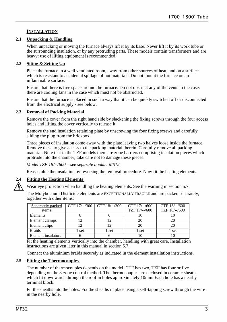
The Molybdenum Disilicide elements are EXCEPTIONALLY FRAGILE and are packed separately, together with other items:
Separately packed items
CTF 17/--/300
CTF 18/--/300
CTF 17/--/600 TZF 17/--/600
CTF 18/--/600 TZF 18/--/600
Elements 6 6 10 10 Element clamps 12 12 20 20 Element clips 12 12 20 20 Braids 1 set 1 set 1 set 1 set Element insulators 6 6 10 10
Fit the heating elements vertically into the chamber, handling with great care. Installation instructions are given later in this manual in section 5.7.
Connect the aluminium braids securely as indicated in the element installation instructions.
2.5 Fitting the Thermocouples The number of thermocouples depends on the model. CTF has two, TZF has four or five
depending on the 3-zone control method. The thermocouples are enclosed in ceramic sheaths which fit downwards through the roof in holes approximately 10mm. Each hole has a nearby terminal block.
Fit the sheaths into the holes. Fix the sheaths in place using a self-tapping screw through the wire in the nearby hole.
MF32 3

1700-1800° Tube
Insert the thermocouples and connect them to the terminal blocks. The leg of the thermocouple with a blue paint mark is the negative. The negative side of the connecting cable is marked with a double number (e.g. 11).
2.6 Electrical Connections Connection by a qualified electrician is recommended. The /300 models are designed only for single phase electrical supplies with or without neutral.
The larger models may be made for 1- or for 3-phase use. The furnace must be connected only to the type and voltage of supply for which it was ordered.
The voltage or range of voltages on which the furnace may be operated is given on the furnace rating label. Check that the supply voltage is compatible with the voltage on the label, and that the current capacity is sufficient for the amperage on the label, before connection to the supply. A table of the most common ratings is given in section 8.1 of this manual.
The supply point must be within reach of the furnace operator and must incorporate either an isolating switch which operates on all live conductors, or a quickly removable plug.
The supply MUST incorporate an earth (ground). CONNECTION DETAILS supply type Supply Terminal label Cable colour Live-Neutral Reversible or Live-Live 1-phase L Brown To live to either power conductor N Blue To neutral to the other power conductor PE Green/Yellow To earth (ground) to earth (ground) Supply Terminal label Cable colour 3-phase L1 Black to phase 1 L2 Black to phase 2 L3 Black to phase 3 N Light Blue to neutral except delta PE Green/Yellow to earth (ground)
2.7 Inserting a Tube If a work tube is supplied with the furnace, then the hole through the insulation is correctly sized.
Carefully line up the tube and ease it through the chamber. Using a pole such as a broom handle may help with this operation.
For a tube of customer supply, ensure that there is approximately 1mm of free play sideways and upwards. If the tube is too tight it will crack when heated. A tight hole can be eased by rotating the tube, which has a sufficiently abrasive surface. Remove loose dust with a domestic vacuum cleaner. Safety note: see section 5.2.
If the holes in the insulation are too large, please consult Carbolite for technical assistance.
If a long tube is specified, then a pair of cylindrical end-guards is supplied. Bolt these onto the furnace ends. The guards incorporate a hookbolt and strap arrangement for supporting the tube, to prevent failure from mechanical stress. These should be adjusted to take the weight of the tube without lifting it clear of the insulation.
2.8
4 MF32

1700-1800° Tube
Internal Work Tube Supports Work tubes may sag at high temperatures. The furnace is fitted with internal tube supports which
should be manually adjusted to suit the tube diameter. With the tube fitted into the furnace, remove the back panel and identify the tube supports. In the
/300 models, there is 1 support. In the /600 models, there are 3. Adjust each support in turn, as follows:
- loosen the ring clip using a screwdriver; - push the ceramic tube upward until it just touches the
bottom of the work tube; - retighten the ring clip.
Note that it is advisable to lower the support tubes if the work tube is removed or replaced, and later readjust them.
2.9 Tube Fittings (if ordered) For optimum temperature uniformity, insulating plugs should be placed in the tube ends as shown
in fig.1. With a long work tube, the stem of the plug assembly should line up with the end of the tube as in fig.2. Alignment of radiation shields is similar to that of plugs.
If stainless steel seals with gas inlets are supplied they are to be fitted as shown in fig.3; the stem of any insulating plug or radiation shield should touch the seal.
If heavy fittings are to be clamped to the end of an extended work tube they can increase the bending stress at the centre of the tube. Support such fittings in such a way that expansion of the tube is allowed.
3.0
MF32 5

1700-1800° Tube
OPERATION The instructions for operating the temperature controller are given in a separate manual. If the furnace is fitted with a time switch, see also the supplementary manual MS03. If cascade control is fitted, see the supplementary manual MS07.
3.1 Operating Cycle (CTF models) The furnace is fitted with a combined Supply light and Instrument switch. The light is on
whenever the furnace is connected to the supply. The switch cuts off power to the controllers and contactor.
Connect the furnace to the electrical supply. The Supply light should glow. Operate the instrument switch to activate the temperature controller; the O position is off, the
I position on. The controller becomes illuminated and goes through a short test cycle. Adjust the main temperature controller – see the controller manual. Set the overtemperature controller to a temperature a little (say 15°C) above the maximum
setpoint of program temperature, according to the instructions in the appropriate manual. Unless a time switch is fitted and is off, the furnace starts to heat up. The Heat light(s) glow(s)
brightly at first, more dimly as the furnace temperature approaches a program setpoint. If the overtemperature trip operates then an indicator or message in the overtemperature controller
flashes, and the heating elements are isolated. Find and correct the cause before resetting the overtemperature controller according to the instructions in the appropriate manual.
To switch the furnace off, set the Instrument switch to off. If the furnace is to be left off, isolate it from the electrical supply.
3.2 Operating Cycle (TZF) See section 3.3 for a description of the control methods A, B & C.
The furnace is fitted with a combined Supply light and Instrument switch. The light is on whenever the furnace is connected to the supply. The switch cuts off power to the controllers and contactor.
Connect the furnace to the electrical supply. The Supply light should glow. Operate the instrument switch to activate the temperature controller; the O position is off, the
I position on. The controller becomes illuminated and goes through a short test cycle. Control methods A & B: Set the slave (end zone) controllers to the desired offset temperature,
usually zero. Set the main (central) temperature controller to the desired setpoint or program. See the separate manual(s) for the controller(s).
Control method C: Set the three controllers to the desired temperatures. See the separate manual(s) for the controller(s).
Set the overtemperature controller to a temperature a little (say 15°C) above the maximum setpoint of program temperature, according to the instructions in the appropriate manual.
Unless a time switch is fitted and is off, the furnace starts to heat up. The Heat light(s) glow(s) brightly at first, more dimly as the furnace temperature approaches a program setpoint.
If the overtemperature trip operates then an indicator or message in the overtemperature controller flashes, and the heating elements are isolated. Find and correct the cause before resetting the overtemperature controller according to the instructions in the appropriate manual.
To switch the furnace off, set the Instrument switch to off. If the furnace is to be left off, isolate it from the electrical supply.
3.3 3-zone Control Methods
6 MF32

1700-1800° Tube
Applicable to TZF only. The TZF is designed to achieve an extended uniform temperature zone by the use of three control zones. The control zones are typically linked so that they are all follow the central controller in a master-slave approach; there are two ways of doing this. Alternatively independent control zones may be ordered. There are thus three control methods (A, B & C). A. Back-to-Back Thermocouples This is the most commonly supplied option.
The central zone is controlled directly by the central temperature controller. Each end zone thermocouple is wired in opposition to a central reference thermocouple, and the small voltage resulting when the zones are at different temperatures is used by the end zone controller. The circuit diagram in section 7.2 shows the thermocouple arrangement.
Set the "setpoint" of the end zone controllers to zero. Sometimes a furnace using this type of control does not cool down: the end controllers try to
remain at the central temperature. Should this occur, contact Carbolite’s technical department. 2132 Slave Controller Navigation Diagram Home
List Access
List °C/F/k ACCS
°C/F/k codE
Zone temperature difference
home list 0.0
Used in factory configuration; not accessible to the operator
B. Retransmission of Setpoint In this system the centre zone controller informs the end-zone controllers of the setpoint that they
are to follow. Additional communication modules are fitted in the controllers, rather than an additional thermocouple as in A.
It is possible to switch off the master-slave control and allow the controllers to work independently. On the end-zone controllers, scroll down to L-r and press Up or Down to alter the value from rmt (remote) to Loc (local). There is no need to alter the centre controller. C. Independent Control In this case the three controllers are completely independent. Note that it is not possible to maintain very different zone temperatures because of heat transfer within the work tube.
3.4
MF32 7

1700-1800° Tube
General Operating Advice Heating element life is shortened by use at temperatures close to maximum. Do not leave the
furnace at high temperature when not required. The maximum temperature is shown on the furnace rating label and on the back page of this manual. The furnace can be cycled between room temperature and maximum without a detrimental effect on element life - but see the notes on tube life.
On first installing the elements, and on subsequent element replacement, run the furnace at 1500°C for an hour to create a protective glaze on the element surface.
The furnace elements are very susceptible to mechanical shock. Take great care when moving the furnace.
3.5 Operator Safety Ceramic materials used in furnace manufacture can become conduction at high temperature.
Avoid using conductive tools within the work tube without first isolating the elements. The elements are isolated (via a contactor) when the instrument switch is off.
If a metal work tube is used, it must be earthed (grounded). Note that the furnace temperature should be limited if a metal tube is used.
Ensure that there are no inflammable objects placed in such a way that the work tube could break and fall on them.
3.6 Tube Life A ceramic work tube may crack if workpieces are inserted
too quickly or at temperatures below 900°C (when the tube is more brittle). Large pieces should also be heated slowly to ensure that large temperature differences do not arise.
Poor thermal contact should be encouraged between the workpiece and the tube; crucibles or boats should be of low thermal mass and should have feet to reduce the contact with the tube (fig. 4).
Avoid metal directly touching the work tube - see the safety warning above. Do not set too high a heating rate. Large diameter tubes are more susceptible to thermal shock
than smaller. A general rule for maximum heating rate is 400/internal diameter (°C/min); for 75mm i/d tubes this comes to 5°C per minute. The controller can be set to limit the heating rate.
3.7 Pressure Work tubes are not able to accept high internal pressure. When gas seals or similar fittings are in
use, the gas pressure should be restricted to a maximum of 0.2 bar (3 psi). A pressure of about half of that should normally be sufficient to achieve the desired flow rate. The customer must ensure that the exhaust path from the tube is not blocked, so that excess pressure does not occur.
3.8 Thermocouples - Warnings (1) The output from 1700-1800°C thermocouples when used regularly at temperatures greater than
1650°C can deteriorate and decrease with age. Customers are advised periodically to check the thermocouple output, either by a calibration test,
or by comparing the output with a new reference thermocouple which has been subjected to high temperatures for a minimum length of time.
Failure to check the thermocouple may result in overheating of the work and the furnace. (2) The thermocouples fitted to these models give very low outputs below about 600°C, and do not
give accurate readings at low temperatures. The furnaces are not intended to be operated below 600°C.
8 MF32

1700-1800° Tube
4.0
MF32 9

1700-1800° Tube
MAINTENANCE 4.1 Routine Maintenance No routine maintenance is required. The outer surfaces may be cleaned with a damp cloth. Do not
allow water to enter the interior of the case, tube or control box. Do not clean with organic solvents.
4.2 Calibration After prolonged use the controller and/or thermocouple could require recalibration; see the
warning about thermocouples in section 3.8. This would be important for processes which require accurate temperature readings or which use the furnace close to its maximum temperature. A quick check using an independent thermocouple and temperature indicator should be made from time to time to determine whether full calibration is required. Carbolite can supply these items.
Depending on the controller, the controller manual may contain calibration instructions.
4.3 After Sales Service Carbolite’s service division (Thermal Engineering Services) has a team of Service Engineers capable of repair, calibration and preventive maintenance of furnace and oven products at our customers’ premises throughout the world. We also sell spares by mail order. A telephone call or fax often enables a fault to be diagnosed and the necessary spare part despatched.
Each furnace has its own record card at Carbolite. In all correspondence please quote the serial number, model type and voltage given on the rating label of the furnace. The serial number and model type are also given on the front of this booklet when supplied with a furnace.
To contact Thermal Engineering Services or Carbolite see the back page of this manual.
4.4 Recommended Spares Kits Carbolite can supply individual spares, or a kit of the items most likely to be required. Ordering a
kit in advance can save time in the event of a breakdown. Each kit comprises one thermocouple, one sheath, one power thyristor, and a set of elements, clips and braids. It is advisable also to obtain element clamps and insulators (not included in kit).
When ordering spares please quote the model details as requested above.
4.5 Power Adjustment (Controller) The furnace controller incorporates a power limit parameter OP.Hi which is usually inaccessible to
the operator. Occasionally the power limit is set to zero to permit demonstration of the controls without the
heating elements taking power. In this case the power limit is accessible to the operator and may be reset to its standard value of 100.
4.6 Power Adjustment (Thryristor) The current-limiting thyristor stacks which control power to the elements are fitted with an adjustable resistor which is factory set to limit the maximum current supplied. In the event of a change of supply voltage, or the fitting of a new thyristor, further adjustment may be required.
The maximum element currents for the various models are listed in section 8.2. Please contact Carbolite for further information.
4.7 Work Tube Supports Occasionally the internal work tube supports may need adjusting. See section 2.8.
5.0
10 MF32
1700-1800° Tube
REPAIRS & REPLACEMENTS 5.1 Safety Warning – Disconnection from Supply Always ensure that the furnace is disconnected from the supply before repair work
is carried out.
5.2 Safety Warning - Refractory Fibrous Insulation This furnace contains refractory fibres in its thermal insulation. These materials
may be in the form of fibre blanket or felt, vacuum formed board or shapes, mineral wool slab or loose fill fibre.
Normal use of the furnace does not result in any significant level of airborne dust from these materials, but much higher levels may be encountered during maintenance or repair.
Whilst there is no evidence of any long term health hazards, we strongly recommend that safety precautions are taken whenever the materials are handled.
Exposure to dust from fibre which has been used at high temperatures may cause respiratory disease. When handling fibre always use an approved mask, eye protection, gloves and long sleeved clothing. Avoid breaking up waste material. Dispose of waste fibre in sealed containers. After handling rinse exposed skin with water before washing gently with soap (not detergent). Wash work clothing separately.
Before commencing any major repairs we recommend reference to the European Ceramic Fibre Industry Association Bulletin No. 11 and the UK Health and Safety Executive Guidance Note EH46.
We can provide further information on request. Alternatively our service division can quote for any repairs to be carried out at your premises or ours.
5.3 Temperature Controller Replacement 2132, 2416, 2408 etc. Ease apart the two lugs at the side; grip the instrument and withdraw it from
its sleeve; push in the replacement.
5.4 Fuse Replacement Access to internal fuses is by removal of the furnace cover or back panel. See section 8.1 for
details of fuses fitted.
5.5 Thermocouple Replacement Disconnect the furnace from the supply, and remove the top cover. In the case of TZF 18/--/600,
remove the back panel, as the thermocouples are horizontal. Make a note of the thermocouple connections. The negative leg of the thermocouple is marked
blue. The “compensating” cable for 1700 & 1800°C thermocouples is plain copper. Disconnect the thermocouple from its terminal block. Bend the metal tag, or release the screw, to release the thermocouple sheath; withdraw the sheath,
and shake out any fragments of thermocouple. Re-assemble with a new thermocouple observing the colour coding, ensuring that the
thermocouple is not twisted as it is being inserted and that the metal tag is bent back, or the screw inserted, to grip the sheath.
5.6
MF32 11

1700-1800° Tube
Insulation Replacement After any replacement of insulation material, run the furnace at 1500°C to burn off volatile matter.
Do this is a well ventilated area, without the work tube in place.
5.7 Element Installation & Replacement Safety Warning – Molybdenum Disilicide elements. The elements form a glazed surface when heated. Internal stresses can form through heating and cooling which render the glaze fragile. The glaze can sometimes splinter into a shower of sharp particles when handled. Always wear eye protection when handling the elements.
Handle the heating elements with extreme care as they are very fragile. Also, avoid touching the heating surface (the thin part of the element).
Replacement: Note the length of element above the fixing clamps before starting. Remove the aluminium braids and clips. Remove the clamp, which has a screw fixing. Lift out the old element and insulation piece (element block): handle the insulation piece with care as it is fragile.
The element diagram shows the items which must be assembled and fitted. Examine and identify the loose components. There are variations in the positions of the braids which connect the elements: the rule is that for single phase all elements are in series; for 3-phase or 3-zone, each phase or zone has elements in series.
Fit the insulation piece (element block) to the element. Locate the clamps over the element, and tighten carefully. Lower the element into position, and connect the braids using the clip tool provided or hand pressure, depending on the type of clip.
Ensure that the element is correctly placed: the thin part of the element legs should be entirely within the heating chamber; the element should not touch the bottom of the chamber, nor the work tube.
Replacement: heat up the furnace to a moderate temperature and ensure that the furnace is controlling properly, in case the previous element failure resulted from a fault in the control system.
After installing new elements run the furnace at 1500°C for an hour. This creates a protective glaze on the element surface.
12 MF32
larger clips require clip tool, comprising two levers smaller clips do no require clip tool

1700-1800° Tube
Element Connections Example: TZF 17/--/600
Example: CTF 17/--/300
Note: /300 models have 6 elements in series
CTF /600 single phase models have 10 elements in series CTF /600 3-phase models have 4 els in S – 2 els in S – 4 els in S TZF /600 models have 2 els ins S – 6 els in S – 2 els in S
6.0
MF32 13

1700-1800° Tube
FAULT ANALYSIS A. Furnace Does Not Heat Up
1. The HEAT light is ON
An ohm meter applied to the element circuit shows an open circuit
A heating element has failed
2. The HEAT light is OFF
The controller shows a very high temperature or a code such as S.br
The thermocouple has broken or has a wiring fault
The controller shows a low temperature
The door switch may be faulty or need adjustment
The thyristor fuse may have blown
The power thyristor could be failing to switch on due to internal failure, faulty wiring from the controller, or faulty controller
There are no lights glowing on the controller
The SUPPLY light is ON
The controller may be faulty or not receiving a supply due to a faulty switch or a wiring fault
The SUPPLY light is OFF
Check the supply fuses and any fuses in the furnace control compartment
B. Furnace Overheats
1. The HEAT light goes OFF with the instrument switch
The controller shows a very high temperature
The controller is faulty
The controller shows a low temperature
The thermocouple may have been shorted out or may have been moved out of the furnace
The thermocouple may be mounted the wrong way round
The controller may be faulty 2. The HEAT light
does not go off with the instrument switch and the fault persists when a 2A control fuse is removed from its fuse-holder
The power thyristor has failed “ON”
Check for an accidental wiring fault which could have overloaded the thyristor. Isolate the furnace if this fault persists.
7.0
14 MF32
1700-1800° Tube
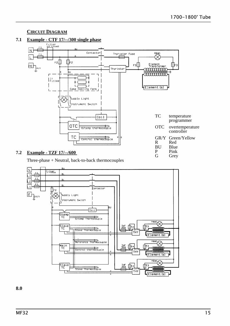
CIRCUIT DIAGRAM 7.1 Example - CTF 17/--/300 single phase 7.2 Example - TZF 17/--/600
Three-phase + Neutral, back-to-back thermocouples
TC temperature programmer
OTC overtemperature controller
GR/Y Green/Yellow R Red BU Blue P Pink G Grey
8.0
MF32 15
1700-1800° Tube
FUSES & POWER CONTROL 8.1 Fuses F1 & F2 - see the example circuit diagram. F1 Supply Fuses: Supply fuses are not fitted internally unless the furnace is also fitted with a supply cable; when
fitted they are of GEC Safeclip of the type shown. Customers should fuse at the rating shown. F2 Control Fuses: 2 Amp type F 30mm x 6mm Thyristor Fuse: Ferraz Protistor of the rating shown. Note that, unlike most fuses, protistor fuses
are correctly rated at a higher current than the thyristor they are protecting.
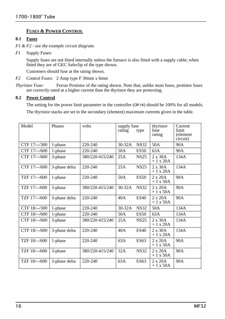
8.2 Power Control The setting for the power limit parameter in the controller (OP.Hi) should be 100% for all models. The thyristor stacks are set to the secondary (element) maximum currents given in the table.
Model Phases volts supply fuse rating type
thyristor fuse rating
Current limit (element circuit)
CTF 17/--/300 1-phase 220-240 30-32A NS32 50A 90A CTF 17/--/600 1-phase 220-240 50A ES50 63A 90A CTF 17/--/600 3-phase 380/220-415/240 25A NS25 2 x 30A
+ 1 x 20A 134A
CTF 17/--/600 3-phase delta 220-240 25A NS25 2 x 30A + 1 x 20A
134A
TZF 17/--/600 1-phase 220-240 50A ES50 2 x 20A + 1 x 50A
90A
TZF 17/--/600 3-phase 380/220-415/240 30-32A NS32 2 x 20A + 1 x 50A
90A
TZF 17/--/600 3-phase delta 220-240 40A ES40 2 x 20A + 1 x 50A
90A
CTF 18/--/300 1-phase 220-240 30-32A NS32 50A 134A CTF 18/--/600 1-phase 220-240 50A ES50 63A 134A CTF 18/--/600 3-phase 380/220-415/240 25A NS25 2 x 30A
+ 1 x 20A 134A
CTF 18/--/600 3-phase delta 220-240 40A ES40 2 x 30A + 1 x 20A
134A
TZF 18/--/600 1-phase 220-240 63A ES63 2 x 20A + 1 x 50A
90A
TZF 18/--/600 3-phase 380/220-415/240 32A NS32 2 x 20A + 1 x 50A
90A
TZF 18/--/600 3-phase delta 220-240 63A ES63 2 x 20A + 1 x 50A
90A
16 MF32

Thank you for reading this data sheet.
For pricing or for further information, please contact us at our UK Office, using the details below.
UK OfficeKeison Products,
P.O. Box 2124, Chelmsford, Essex, CM1 3UP, England.Tel: +44 (0)330 088 0560Fax: +44 (0)1245 808399
Email: [email protected]
Please note - Product designs and specifications are subject to change without notice. The user is responsible for determining the suitability of this product.