b-12 photo page - camco furnace, hydrogen and high … info.pdf · sight glass for calibration...
TRANSCRIPT
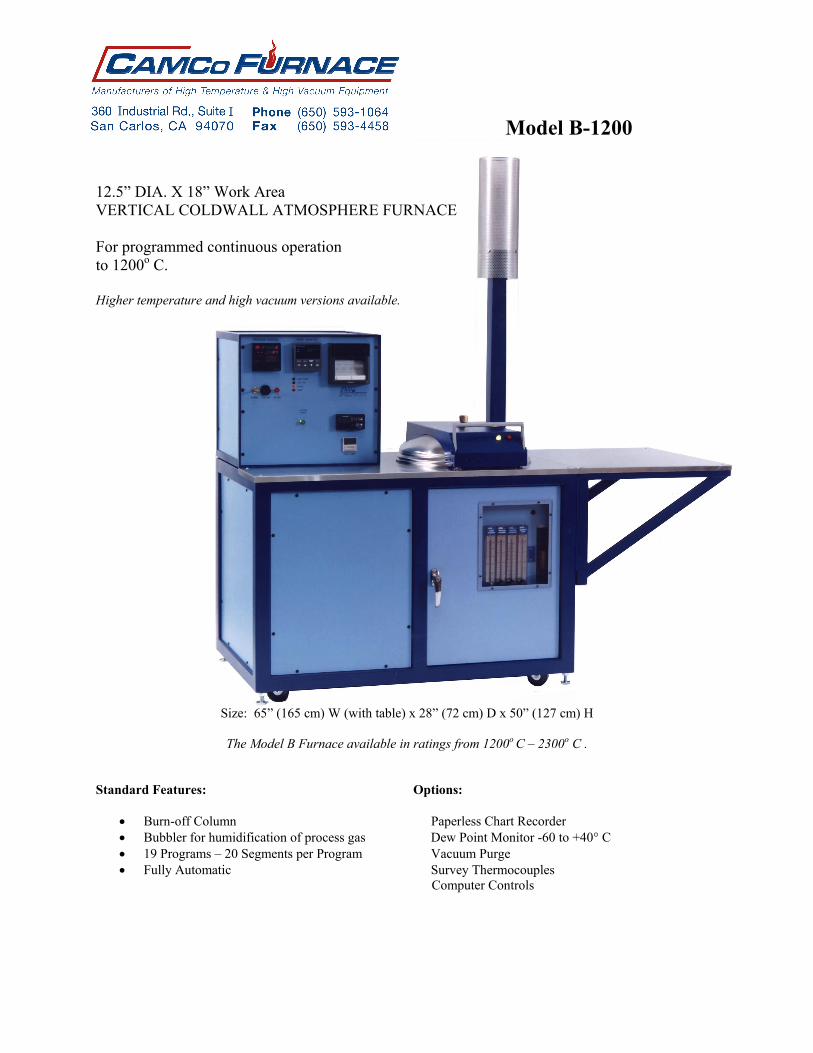
Model B-1200
12.5” DIA. X 18” Work Area VERTICAL COLDWALL ATMOSPHERE FURNACE For programmed continuous operation to 1200o C. Higher temperature and high vacuum versions available.
Size: 65” (165 cm) W (with table) x 28” (72 cm) D x 50” (127 cm) H
The Model B Furnace available in ratings from 1200o C – 2300o C .
Standard Features: Options:
Burn-off Column Paperless Chart Recorder Bubbler for humidification of process gas Dew Point Monitor -60 to +40° C 19 Programs – 20 Segments per Program Vacuum Purge Fully Automatic Survey Thermocouples
Computer Controls

Specification Sheet Equipment Model: B-1200 Furnace Type Coldwall, Vertical, Top Loading
Maximum Temperature 1250° C.
Hot Zone 12.5” (32cm) Dia. X 18” (45cm) H. Nominal
Frame Dimensions 44” (112cm) W. x 28” (72cm) D. x 50” (127cm) H.
Power Requirements 480V 3 Ph. 60A 60 Hz or 240V 3 Ph. 120A 60 Hz.
415V 3 Ph. 60A 50Hz
Gas Requirements 25 – 50 psig, Nitrogen ¼” Swagelok
25 – 50 psig, Hydrogen ⅜” Swagelok
Purge gas is Nitrogen. Process gas is Hydrogen or Nitrogen or a mixture of both. Process gas can be humidified via a heated bubbler to over 18° C. Dewpoint. Cooling Requirements - 25 psig at zero back pressure, at 4 gallons per min. Note: Maximum back pressure is 15 psig. Heat up ramp rate 50° C per minute - empty chamber. All Molybdenum Hot Zone & Elements. All Insulators are made of High Alumina. Standard Features: Options:
Burn-off Column Extension Table Bubbler for humidification of process gas Cable Hoist Equipment on casters to roll into place Paperless Chart Recorder Honeywell Controls - Ramp & Soak Dewpoint Monitor -60 to +40° C DCP302 Program Controller Vacuum Purge UDC2500 Overtemp Control Tower Indicator Lights 19 Programs - 20 Segments per Program Computer Controls Sight glass for calibration melts Survey Thermocouples Active Braze Control Fully Automatic - One button push starts the run.
Automatically it will purge → process gas fill → ramp to temperature and soak → bubbler for humidification of process gas → cooldown → post purge.

CAMCo equipment description, B-1200, Pg. 1
Equipment Description CAMCo 12.5” Dia. X 18” H., 1200° C. REDUCING/INERT ATMOSPHERE, COLDWALL FURNACE For Automatic, Programmed Operation to 1200° C Model B-1200 Overview The Concepts & Methods Co., Inc. "B-12", reducing/inert atmosphere furnace is designed to reproducibly metallize, braze, clean fire and otherwise process loads of up to 12 inches diameter by 16 inches high. Materials may be lowered onto it’s hearth within the 12” dia. by 18” high work area. One of 19 selected ramp and soak programs is accurately controlled up to 1250° C. The furnace gas controls, thermal controls and interlocks are integrated in a single Microprocessor unit to assure simple, reliable, programmed operation. The furnace chamber is located within the right half of the base unit and is of the "coldwall" variety. It incorporates a Molybdenum heating element of six sections supported by high alumina insulators. This surrounds the twelve-inch diameter by eighteen-inch high work area. Work is placed on a 12” molybdenum hearth, which in turn is held by the support structure within the chamber. A series of four cylindrical heat shields, the bottom end stack of seven shields, and the removable top shield stack of eight heat shields surround the element. A double wall, water jacketed stainless steel chamber contains these items as well as the six insulated power feedthroughs, control and work thermocouples and other required features. The water-jacketed cover assembly is reliably silicone gasket sealed to the chamber through use of an interlocked camming latch. A 5/8" diameter sightport is located at the center of the cover, and its centerline is vertical. In registration with this are holes of approximately 7/16” diameter, which penetrate the top heat shield stack. A "flag" in close thermal proximity to the work monitoring thermocouple may thus be watched, and a precise calibration thereby obtained. This viewpoint can also be used in conjunction with an optical pyrometer. The sight glass is sealed through use of an "O" ring, and is readily removable to facilitate cleaning or replacement. There is a feedthrough at the side of the chamber and related holes in the cylindrical shields that allow survey thermocouples to be inserted to monitor actual temperature of load. These thermocouples can be used in conjunction with the “Active Closed Loop Braze Control Option”. Base Unit The base unit measures approximately 46" wide by 29" deep (to fit through a standard door) by 50" high. Its' substantial frame is constructed of heavy wall square steel tubing. Service access is readily gained through a hinged steel front mounted door and the removable side rear and left front panels. The plate steel floor within the left half of the base unit supports the heavy heater power transformer and closes the bottom. The left half, containing the power components and electronics is isolated from the right by an internal airflow-directing baffle. A fan at the rear of the base unit draws cooling air through a replaceable filter element to cool the power control unit and transformer. In addition, the base frame supports the instrument console, chamber, and cover hinge and latch assemblies. A convenient feature is the inclusion of recessed heavy-duty casters. The unit is easily rolled into place, and the leveling feet lowered to immobilize and level the equipment. The stainless steel top provides an area for convenient load preparation, and completes closure of the base unit. An optional extension table (23” x 28”) with a stainless steel top is bolted to the right side of the frame to increase working area for loading and unloading. The finish used on this, and all CAMCo equipment is baked powder coating chosen for its' durability and solvent

CAMCo equipment description, B-1200, Pg. 2
resistance. Temperature Control Temperature control and monitoring signals are achieved from two type "K" thermocouples. Multi-stage programmed Ramp & Soak Temperature control and atmosphere sequencing is achieved through use of a Honeywell Micro process controller. The controller receives its' input signal from a thermocouple located close to the heating element. Thermocouple break protection assures that heating power is removed from the furnace in the event of sensor failure. A second thermocouple is used to monitor the load. This is a flexible, Inconel sheathed type “K” thermocouple that can be attached directly to the load. It is monitored on a second input channel located on the microprocessor controller. This signal can be used with an alarm for process load control. Overtemp & Safe Access Control Over-temperature monitoring is provided by a third thermocouple located within close proximity to the load. It drives a Honeywell UDC2500 process monitor, which provides digital readout of the load area temperature and provides an over-temperature shutdown signal. The process monitor also provides a safe access temperature interlock and run complete signal for the operator. Operation The work is loaded into the furnace, the top heat shield stack inserted, the cover closed and latched. One of nineteen selectable, user programmed thermal profiles is chosen, and the "start" key pressed. Gas flows and dew point are set. The furnace will automatically pre-purge, process gas fill, perform the pre-programmed ramp & soak temperature profile, cool down, and post purge. Upon completion of the cooldown portion of the program, the chamber is opened and unloaded. Power Control Power is proportionally controlled through use of a digitally controlled SCR three phase power module. This unit is phase angle fired control, and includes three-phase current limiting made necessary by the strongly positive resistivity coefficient of the heating elements. In the event of a power outage at higher temperature, the load temperature would drop to a level where a hard application of heat might thermally shock damage the parts. In this event, an abort relay will trip, and the program will resume and time out under process atmosphere without the application of heat. Impedance match of the heating elements to the incoming power is accomplished through the conservatively rated 40KVA transformer driven by this power module. Atmosphere Control Customer supplied Hydrogen and Nitrogen gasses are admitted to the chamber through programmed valves and preset flow meters. An interlock is included which provides for automatic Nitrogen purge in the event of loss of Hydrogen/Nitrogen or chamber pressure. Operator set flow meters control the flow of gasses to achieve the appropriate operating atmosphere. Included is a system which, when called to do so by the installed program, humidifies a portion of the selected process gas via a bubbler column. This gas is then recombined with the remaining process gas in a pre-selected ratio to obtain the desired process dew point. The included bubbler column will humidify the process gas to a dew point of up to 20° C. Higher dew point equipment, and controlled temperature bubblers are available. Exhaust gas is routed through a check valve and out a fitting at the rear of the cabinet. This valve establishes a slight positive pressure when the door is closed and sealed. As a safety feature, absence of this pressure prevents admission of Hydrogen and inhibits the application of heater power. An exhaust gas burn-off column electronically ignites the waste gas. Ignition is called for automatically at all times that Hydrogen is called for, and the unit attempts re-ignition should the flame be inadvertently extinguished. The igniter is automatically tested to assure proper operation each time a run is started. All gas plumbing and components are Stainless Steel. All gas connections are high quality high-pressure Swagelok fittings.

CAMCo equipment description, B-1200, Pg. 3
Standard Safety Features Thermocouple break protection (Thermocouple burn-up) assures that heating power is removed from the furnace in the event of sensor failure. Over-temperature indication is read on a separate control module from the monitor thermocouple. This over-temp alarm causes the heating elements to shut down as a further backup. Other numerous interlock functions protecting the operator and equipment include:
Panel Interlock High Cabinet Temperature Low Coolant Flow Low Gas Pressure Switches Hydrogen is prohibited from entering the system and heating cannot begin until the chamber cover is
closed, sealed and purged. At the end of a programmed run the chamber is inhibited from being opened until the work has cooled to a predefined safe temperature.
A Purge Assure Circuit provides an internally set minimum timed Nitrogen purge regardless of the program status whenever power or the program is interrupted.
A normally open solenoid valve on the nitrogen purge circuit assures that the furnace is always under a constant flow of gas in the event of a power failure. This feature will purge the chamber of hydrogen so that the furnace chamber will have a safe atmosphere to be opened to.
Documentation Facilities information is supplied to assist in site preparation for installation. An operating manual is supplied with the equipment. Worksheets included in the manual provide a convenient form to depict the desired process for entry into the microprocessor controller. The worksheets also serve as a hard copy of the program. The unit is shipped with an example program stored in memory, depicted by the example worksheet. Wiring and plumbing schematics along with a published spare parts list are also included in the manual. Vendor supplied manuals for the program controller, over-temp, SCR, recorder, dew-pointer, and other small items are supplied in our documentation. A program and operation section has a complete button-by-button push instruction for installation of a generic program. The relatively simple operation of the furnace is well described and documented in the manual. While the furnace is a complete, stand alone unit as described, many applications suggest the inclusion of one or more of the options described in the enclosed data. Other, less commonly ordered options can also be provided. Please inquire.


B-Furnace Hot Zone showing part survey thermocouple and stainless steel fixturing.
Flag melt positioned at center for sight port verification.