installation operation care - hunter douglas · thank you for purchasing hunter douglas horizontal...
TRANSCRIPT

Installation • Operation • Care
Horizontal BlindsPowerView™ Motorization
Wood, Alternative Wood, and 2" Aluminum Horizontals Blinds

CONTENTS
Questions? Call the Hunter Douglas Customer Information Center at 1-888-501-8364.
© 2016 Hunter Douglas. All rights reserved. All trademarks used herein are the property of Hunter Douglas or their respective owners.
Getting Started:Product View ................................................................................................... 1Tools and Fasteners Needed ............................................................................. 2Unpack the Blind .............................................................................................. 2
Installation:Installation Overview ........................................................................................ 3STEP 1 — Install the Brackets .......................................................................... 3
Mount the Installation Brackets — Inside Mount and Ceiling Mount .................. 5Mount the Installation Brackets — Outside Mount ........................................... 7
STEP 2 — Install the Blind ............................................................................. 10STEP 3 — Connect the Power Source ............................................................. 15
Operation:Testing the Blind ............................................................................................ 20Using the PowerView™ Remote ....................................................................... 20Resetting the Blind (If Necessary) .................................................................... 22Complete the Installation ............................................................................... 23Operate the Blind ........................................................................................... 27Troubleshooting ............................................................................................. 27
Care:Removing the Blind (If Necessary) ................................................................... 29Cleaning Procedures ...................................................................................... 29
Child Safety:Warning ....................................................................................................... 30Cord Connector ............................................................................................. 30Cord Cleats .................................................................................................... 31
Declarations ................................................................................................. 32
Warranty ............................................................................................Back Cover
EndBracket2
Hold-DownBracket and Pin
(Optional)
1 Required with 21/2" slat size; optional with 2" slat size2 2" and 21/2" slat sizes* Valance, valance clips, bottom rail, and tassel varies by product
IntermediateBracket
(If Required)
Valance Splice(If Required)
Valance*
Corner Clips forValance Returns
(If Required)
End BracketSpacer Block1
IntermediateBracket
Spacer Block1
BracketShim
2" or 4" ExtensionBrackets (Optional)
End BracketSpacerBlock1
EndBracket2
PowerCable
Valance Clips (Alternative Wood &
Aluminum Blinds)
PowerView™
MotorAssembly
PebbleRemote
SurfaceRemote
12V Battery Wand
Magnetic Valance Clips (Wood and
Natural Elements™ Blinds)
ExtensionCable
DC Power Supply(Optional)
Transceiver Assembly
Manual ControlButton
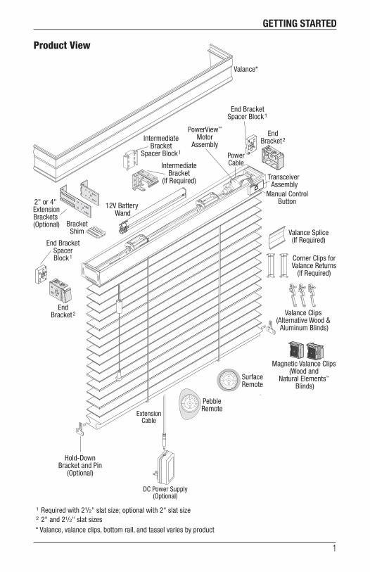
GETTING STARTED
1
Product View
EndBracket2
Hold-DownBracket and Pin
(Optional)
1 Required with 21/2" slat size; optional with 2" slat size2 2" and 21/2" slat sizes* Valance, valance clips, bottom rail, and tassel varies by product
IntermediateBracket
(If Required)
Valance Splice(If Required)
Valance*
Corner Clips forValance Returns
(If Required)
End BracketSpacer Block1
IntermediateBracket
Spacer Block1
BracketShim
2" or 4" ExtensionBrackets (Optional)
End BracketSpacerBlock1
EndBracket2
PowerCable
Valance Clips (Alternative Wood &
Aluminum Blinds)
PowerView™
MotorAssembly
PebbleRemote
SurfaceRemote
12V Battery Wand
Magnetic Valance Clips (Wood and
Natural Elements™ Blinds)
ExtensionCable
DC Power Supply(Optional)
Transceiver Assembly
Manual ControlButton

2
GETTING STARTED
Thank you for purchasing Hunter Douglas horizontal blinds with PowerView™ Motorization. With proper installation, operation, and care, your new blinds will provide years of beauty and performance.
Please thoroughly review this instruction booklet and the packing list before beginning the installation.
Tools and Fasteners Needed
■ Flat blade and Phillips screwdrivers
■ Level (laser level is recommended)
■ Measuring tape and pencil
■ Power drill, drill bits, and 1/4" hex driver (or socket wrench with 1/4" hex socket)
In addition, you will need fasteners designed to work with your specific mounting surface(s).
■ #6 Hex Head Screws (Provided). Two 11/2" screws are provided per installation bracket.
■ Longer #6 Hex Head Screws (Not Provided). If using spacer blocks, use #6 screws long enough for a secure attachment.
■ Drywall Anchors (Not Provided). Use drywall anchors when mounting into drywall.
Unpack the Blind
■ Remove the blind from the package. Keep the packaging until the blind operates to your satisfaction.
■ Refer to the diagrams on the previous pages and check for all necessary parts.
■ Contents of your hardware package may vary depending upon the options chosen.
■ Do not remove the slat protector tape. Doing so will damage the slat finish.
#6 x 11/2"Hex Head Screw
(Provided)
Longer #6 Hex Head Screw for Use with Spacer Blocks
(Not Provided)
16
Do Not Remove
Slat ProtectorTape
GETTING STARTED
3
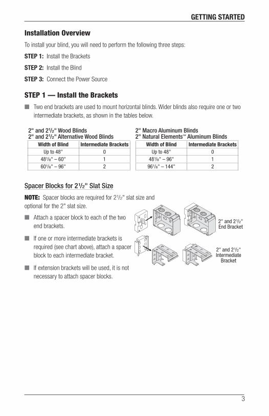
Installation Overview
To install your blind, you will need to perform the following three steps:
STEP 1: Install the Brackets
STEP 2: Install the Blind
STEP 3: Connect the Power Source
STEP 1 — Install the Brackets
■ Two end brackets are used to mount horizontal blinds. Wider blinds also require one or two intermediate brackets, as shown in the tables below.
Spacer Blocks for 21/2" Slat Size
NOTE: Spacer blocks are required for 21/2" slat size and optional for the 2" slat size.
■ Attach a spacer block to each of the two end brackets.
■ If one or more intermediate brackets is required (see chart above), attach a spacer block to each intermediate bracket.
■ If extension brackets will be used, it is not necessary to attach spacer blocks.
2" and 21/2"End Bracket
2" and 21/2"Intermediate
Bracket
Width of Blind Intermediate BracketsUp to 48" 0
481/8" – 60" 1601/8" – 96" 2
Width of Blind Intermediate BracketsUp to 48" 0
481/8" – 96" 1961/8" – 144" 2
2" Macro Aluminum Blinds 2" Natural Elements™ Aluminum Blinds
2" and 21/2" Wood Blinds 2" and 21/2" Alternative Wood Blinds
4
GETTING STARTED
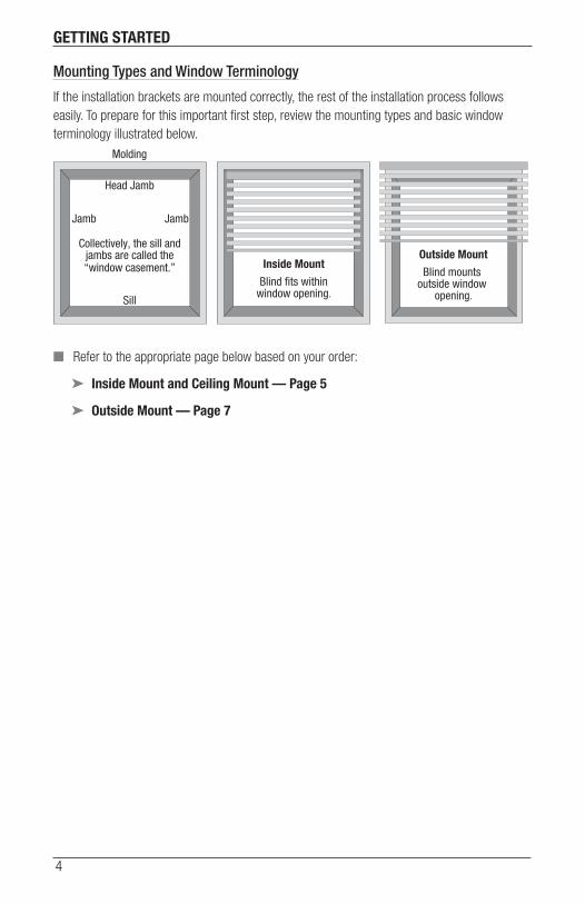
Mounting Types and Window Terminology
If the installation brackets are mounted correctly, the rest of the installation process follows easily. To prepare for this important first step, review the mounting types and basic window terminology illustrated below.
■ Refer to the appropriate page below based on your order:
➤ Inside Mount and Ceiling Mount — Page 5
➤ Outside Mount — Page 7
Outside Mount
Blind mounts outside window
opening.
Inside Mount
Blind fits withinwindow opening.
Collectively, the sill andjambs are called the“window casement.”
Molding
Head Jamb
Sill
Jamb Jamb

INSTALLATION
5
Mount the Installation Brackets — Inside Mount and Ceiling Mount
Attach End Brackets
With inside mounts or ceiling mounts, attach the two end brackets flush against the sides of the window casement or to the ceiling. (See page 7 the outside mount section for positioning the brackets for ceiling mounting.) Choose the most appropriate of the following mounting methods:
■ Inside mount only: Mount the end brackets with one screw through a side hole and one screw through a top hole, as shown below left.
■ Inside mount only: Mount the end brackets with two screws through diagonal side holes.
■ Inside mount or ceiling mount: Top mount the end brackets with screws through the two top holes, as shown below right.
■ Ceiling mount only: If the brackets are flush with the back wall, attach them with one screw through a top hole and one through a rear hole.
■ Use a 3/32" drill bit to drill holes for the mounting screws.
CAUTION: Use drywall anchors when mounting into drywall.
■ Attach the end brackets using the screws provided.
IMPORTANT: The front edges of the brackets must be level and aligned to each other.
NOTE: For blinds with 21/2" slats, spacer blocks are used with inside mounts to position the brackets a minimum of 3/8" from the glass. This prevents the slats from rubbing the glass when they are tilted open.
2" and 21/2"Side/TopMount
2" and 21/2"Top Mount
INSTALLATION
6
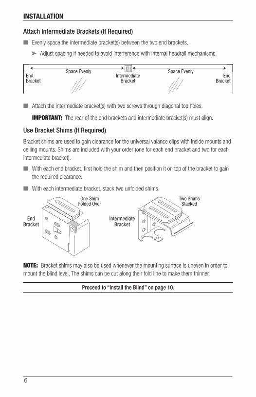
Attach Intermediate Brackets (If Required)
■ Evenly space the intermediate bracket(s) between the two end brackets.
➤ Adjust spacing if needed to avoid interference with internal headrail mechanisms.
■ Attach the intermediate bracket(s) with two screws through diagonal top holes.
IMPORTANT: The rear of the end brackets and intermediate bracket(s) must align.
Use Bracket Shims (If Required)
Bracket shims are used to gain clearance for the universal valance clips with inside mounts and ceiling mounts. Shims are included with your order (one for each end bracket and two for each intermediate bracket).
■ With each end bracket, first hold the shim and then position it on top of the bracket to gain the required clearance.
■ With each intermediate bracket, stack two unfolded shims.
NOTE: Bracket shims may also be used whenever the mounting surface is uneven in order to mount the blind level. The shims can be cut along their fold line to make them thinner.
Proceed to “Install the Blind” on page 10.
IntermediateBracket
EndBracket
EndBracket
Space Evenly Space Evenly
One ShimFolded Over
Two ShimsStacked
EndBracket
IntermediateBracket
INSTALLATION
7
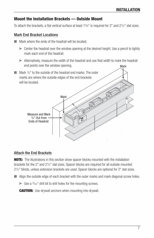
Mount the Installation Brackets — Outside Mount
To attach the brackets, a flat vertical surface at least 13/4" is required for 2" and 21/2" slat sizes.
Mark End Bracket Locations
■ Mark where the ends of the headrail will be located.
➤ Center the headrail over the window opening at the desired height. Use a pencil to lightly mark each end of the headrail.
➤ Alternatively, measure the width of the headrail and use that width to mark the headrail end points over the window opening.
■ Mark 1/4" to the outside of the headrail end marks. The outer marks are where the outside edges of the end brackets will be located.
Attach the End Brackets
NOTE: The illustrations in this section show spacer blocks mounted with the installation brackets for the 2" and 21/2" slat sizes. Spacer blocks are required for all outside mounted 21/2" blinds, unless extension brackets are used. Spacer blocks are optional for 2" slat sizes.
■ Align the outside edge of each bracket with the outer marks and mark diagonal screw holes.
➤ Use a 3/32" drill bit to drill holes for the mounting screws.
CAUTION: Use drywall anchors when mounting into drywall.
Mark
Measure and Mark1/4" Out from
Ends of Headrail
Mark

INSTALLATION
8
■ Attach the end brackets using two screws through diagonal holes.
➤ If using spacer blocks, use #6 screws long enough for a secure installation (21/2" recommended).
IMPORTANT: The tops of the brackets must be level and aligned at the same height.
CAUTION: The rear of the spacer blocks or brackets must be flush against a flat mounting surface. Do not mount brackets on curved molding.
Attach Intermediate Brackets (If Required)
■ Evenly space the intermediate bracket(s) between the two end brackets.
➤ Adjust spacing if needed to avoid interference with internal headrail mechanisms.
■ Attach the intermediate bracket(s) with two screws through diagonal holes.
IMPORTANT: The tops of the end brackets and intermediate bracket(s) must align.
IntermediateBracket
EndBracket
EndBracket
Space Evenly Space Evenly
INSTALLATION
9
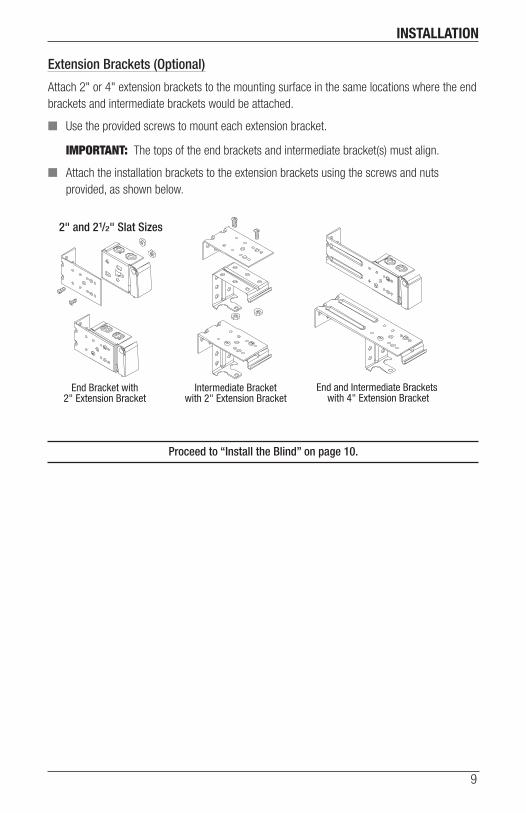
Extension Brackets (Optional)
Attach 2" or 4" extension brackets to the mounting surface in the same locations where the end brackets and intermediate brackets would be attached.
■ Use the provided screws to mount each extension bracket.
IMPORTANT: The tops of the end brackets and intermediate bracket(s) must align.
■ Attach the installation brackets to the extension brackets using the screws and nuts provided, as shown below.
Proceed to “Install the Blind” on page 10.
End Bracket with2" Extension Bracket
Intermediate Bracketwith 2" Extension Bracket
End and Intermediate Brackets with 4" Extension Bracket
2" and 21/2" Slat Sizes
INSTALLATION
10
STEP 2 — Install the Blind
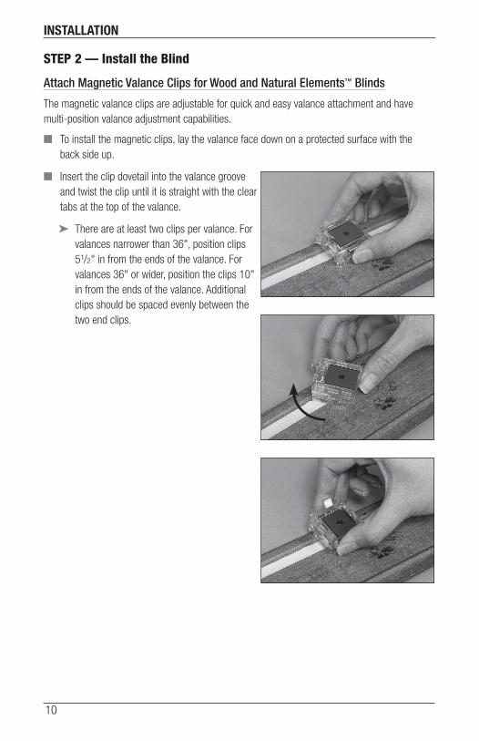
Attach Magnetic Valance Clips for Wood and Natural Elements™ Blinds
The magnetic valance clips are adjustable for quick and easy valance attachment and have multi-position valance adjustment capabilities.
■ To install the magnetic clips, lay the valance face down on a protected surface with the back side up.
■ Insert the clip dovetail into the valance groove and twist the clip until it is straight with the clear tabs at the top of the valance.
➤ There are at least two clips per valance. For valances narrower than 36", position clips 51/2" in from the ends of the valance. For valances 36" or wider, position the clips 10" in from the ends of the valance. Additional clips should be spaced evenly between the two end clips.
INSTALLATION
11
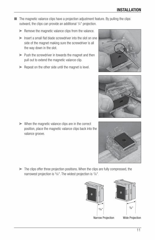
■ The magnetic valance clips have a projection adjustment feature. By pulling the clips outward, the clips can provide an additional 1/4" projection.
➤ Remove the magnetic valance clips from the valance.
➤ Insert a small flat blade screwdriver into the slot on one side of the magnet making sure the screwdriver is all the way down in the slot.
➤ Push the screwdriver in towards the magnet and then pull out to extend the magnetic valance clip.
➤ Repeat on the other side until the magnet is level.
➤ When the magnetic valance clips are in the correct position, place the magnetic valance clips back into the valance groove.
➤ The clips offer three projection positions. When the clips are fully compressed, the narrowest projection is 5/8". The widest projection is 7/8".
5/8"
Narrow Projection
7/8"
Wide Projection

INSTALLATION
12
Attach Universal Valance Clips For Alternative Wood and Aluminum Blinds
With fully recessed inside mounts or ceiling mounts, the valance clips must be installed before mounting the headrail.
■ Attach valance clips 2" from each end of the headrail.
■ Space additional clip(s) evenly between the two end clips so that the valance clips are no more than 36" apart.
■ Do not place the valance clips where they could interfere with any working parts.
■ If desired, the valance may be positioned 1/4" higher by raising the clips one notch up, as shown in the illustration below.
StandardPosition
Raised Clip =Higher Valance
INSTALLATION
13
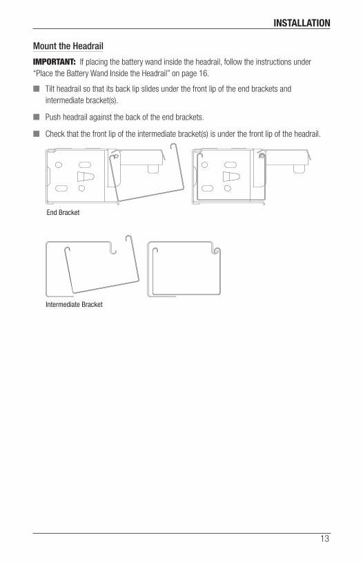
Mount the Headrail
IMPORTANT: If placing the battery wand inside the headrail, follow the instructions under “Place the Battery Wand Inside the Headrail” on page 16.
■ Tilt headrail so that its back lip slides under the front lip of the end brackets and intermediate bracket(s).
■ Push headrail against the back of the end brackets.
■ Check that the front lip of the intermediate bracket(s) is under the front lip of the headrail.
End Bracket
Intermediate Bracket
INSTALLATION
14
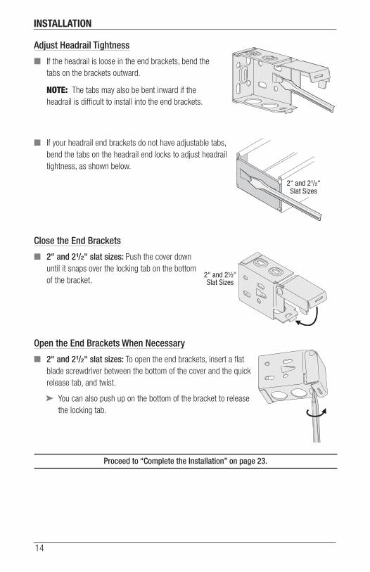
Adjust Headrail Tightness
■ If the headrail is loose in the end brackets, bend the tabs on the brackets outward.
NOTE: The tabs may also be bent inward if the headrail is difficult to install into the end brackets.
■ If your headrail end brackets do not have adjustable tabs, bend the tabs on the headrail end locks to adjust headrail tightness, as shown below.
Close the End Brackets
■ 2" and 21/2" slat sizes: Push the cover down until it snaps over the locking tab on the bottom of the bracket.
Open the End Brackets When Necessary
■ 2" and 21/2" slat sizes: To open the end brackets, insert a flat blade screwdriver between the bottom of the cover and the quick release tab, and twist.
➤ You can also push up on the bottom of the bracket to release the locking tab.
Proceed to “Complete the Installation” on page 23.
13/8"Slat Size
2" and 2½"Slat Sizes
2" and 21/2"Slat Sizes
13/8"Slat Size

INSTALLATION
15
STEP 3 — Connect the Power Source
NOTE: When power is connected to the motor, a green LED inside the manual control button housing will flash to indicate the blind is ready for operation.
■ Refer to the appropriate page based on your order.
➤ For a battery wand, see below.
➤ For a satellite battery wand, see page 16.
➤ For an optional DC power supply, see page 18.
➤ For an optional DC power supply with daisy-chain connections, see page 19.
➤ For an optional Large DC power supply, see the instructions that came with the power supply.
➤ For an optional C-size satellite battery wand, see the instructions that came with the wand.
If You Have a Battery Wand...
Install Batteries into the Battery Wand
NOTE: Hunter Douglas recommends AA alkaline batteries for use with our battery-powered blinds. These will provide approximately one year of operation. Lithium and rechargeable batteries are not recommended.
■ Squeeze the cap latch to release the cap.
■ Remove the cap from the battery wand.
■ Install the batteries according to the instructions on the battery wand label.
■ Replace the cap.
➤ Align the tab with the end of the wand.
➤ Press the cap on until it latches.
Tab Slot
CapLatch
BatteryWand
Squeeze
INSTALLATION
16
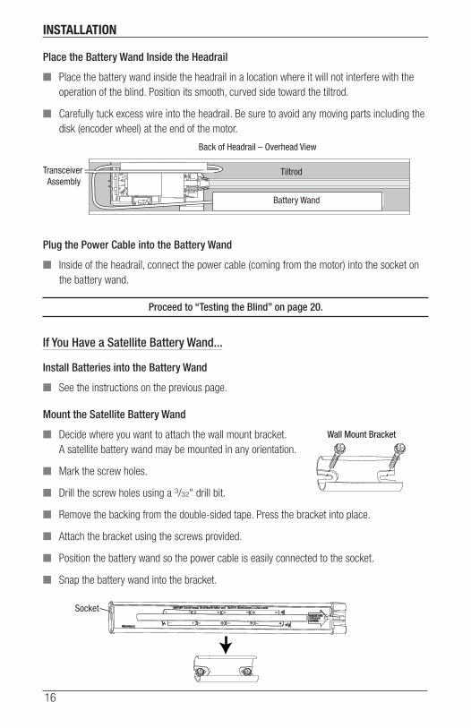
Place the Battery Wand Inside the Headrail
■ Place the battery wand inside the headrail in a location where it will not interfere with the operation of the blind. Position its smooth, curved side toward the tiltrod.
■ Carefully tuck excess wire into the headrail. Be sure to avoid any moving parts including the disk (encoder wheel) at the end of the motor.
Plug the Power Cable into the Battery Wand
■ Inside of the headrail, connect the power cable (coming from the motor) into the socket on the battery wand.
Proceed to “Testing the Blind” on page 20.
If You Have a Satellite Battery Wand...
Install Batteries into the Battery Wand
■ See the instructions on the previous page.
Mount the Satellite Battery Wand
■ Decide where you want to attach the wall mount bracket. A satellite battery wand may be mounted in any orientation.
■ Mark the screw holes.
■ Drill the screw holes using a 3/32" drill bit.
■ Remove the backing from the double-sided tape. Press the bracket into place.
■ Attach the bracket using the screws provided.
■ Position the battery wand so the power cable is easily connected to the socket.
■ Snap the battery wand into the bracket.
Tiltrod
Back of Headrail – Overhead View
Transceiver Assembly
Battery Wand
Wall Mount Bracket
Socket
INSTALLATION
17
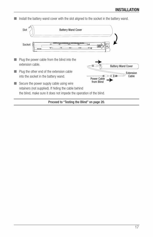
■ Install the battery wand cover with the slot aligned to the socket in the battery wand.
■ Plug the power cable from the blind into the extension cable.
■ Plug the other end of the extension cable into the socket in the battery wand.
■ Secure the power supply cable using wire retainers (not supplied). If hiding the cable behind the blind, make sure it does not impede the operation of the blind.
Proceed to “Testing the Blind” on page 20.
Battery Wand CoverSlot
Socket
Battery Wand Cover
ExtensionCable
Power Cablefrom Blind
INSTALLATION
18
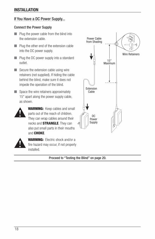
If You Have a DC Power Supply...
Connect the Power Supply
■ Plug the power cable from the blind into the extension cable.
■ Plug the other end of the extension cable into the DC power supply.
■ Plug the DC power supply into a standard outlet.
■ Secure the extension cable using wire retainers (not supplied). If hiding the cable behind the blind, make sure it does not impede the operation of the blind.
■ Space the wire retainers approximately 15" apart along the power supply cable, as shown.
WARNING: Keep cables and small parts out of the reach of children. They can wrap cables around their necks and STRANGLE. They can also put small parts in their mouths and CHOKE.
WARNING: Electric shock and/or a fire hazard may occur, if not properly installed.
Proceed to “Testing the Blind” on page 20.
Power Cablefrom Shading
ExtensionCable
DCPowerSupply
15"Maximum
Wire Retainers
INSTALLATION
19
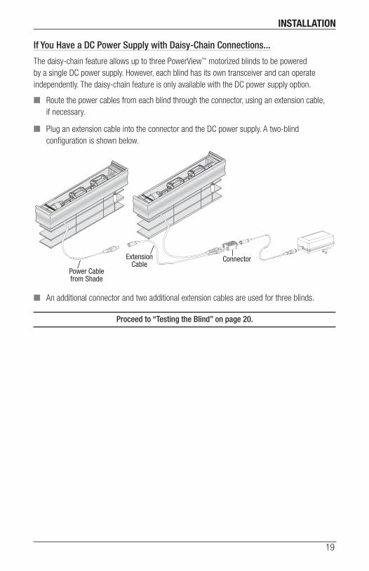
If You Have a DC Power Supply with Daisy-Chain Connections...
The daisy-chain feature allows up to three PowerView™ motorized blinds to be powered by a single DC power supply. However, each blind has its own transceiver and can operate independently. The daisy-chain feature is only available with the DC power supply option.
■ Route the power cables from each blind through the connector, using an extension cable, if necessary.
■ Plug an extension cable into the connector and the DC power supply. A two-blind configuration is shown below.
■ An additional connector and two additional extension cables are used for three blinds.
Proceed to “Testing the Blind” on page 20.
Power Cablefrom Shade
ExtensionCable
Connector
INSTALLATION
20
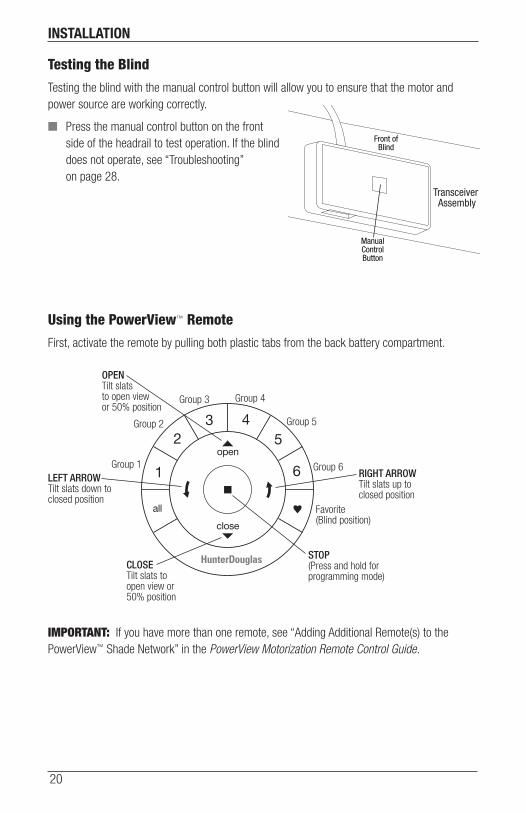
Testing the Blind
Testing the blind with the manual control button will allow you to ensure that the motor and power source are working correctly.
■ Press the manual control button on the front side of the headrail to test operation. If the blind does not operate, see “Troubleshooting” on page 28.
Using the PowerView™ Remote
First, activate the remote by pulling both plastic tabs from the back battery compartment.
IMPORTANT: If you have more than one remote, see “Adding Additional Remote(s) to the PowerView™ Shade Network” in the PowerView Motorization Remote Control Guide.
ManualControlButton
Front ofBlind
Transceiver Assembly
Group 1
Group 2
OPENTilt slats to open view or 50% position
CLOSETilt slats to open view or 50% position
Group 3 Group 4
Group 5
Group 6
Favorite(Blind position)
LEFT ARROWTilt slats down to closed position
RIGHT ARROWTilt slats up to closed position
STOP(Press and hold for programming mode)
OPERATION
21
WarningJoining a Blind to a Group
IMPORTANT: The blind will not operate using the remote until it has been joined to a group.
1. Press and hold ■ STOP for 4 seconds to put remote in program mode. The lights on the remote will flash to indicate it is in program mode.
2. Press the desired group number (1 – 6) on the remote. The backlight for the group number will flash to show it is selected.
3. Press and hold the manual control button on the blind.
4. While continuing to press the manual button, press ▲ OPEN on the remote. The blind will move slightly to indicate it has joined the group. Release the manual control button.
5. Press and hold ■ STOP for 4 seconds to exit program mode. The lights will stop flashing.
Basic Operation
1. To wake up the remote, simply pick it up or press ■ STOP. The last group(s) selected will be highlighted and active.
2. Press “all” or groups 1 – 6 to select specific blind(s) to move. Selected group button(s) will light to show they are selected.
a. Multiple group buttons may be selected at a time.
b. To deselect a group, press the group button again. The backlight for that group button will go out.
3. Press left arrow to tilt slats down to the closed position.
4. Press right arrow to tilt slats up to the closed position.
5. Press ■ STOP to stop the slats’ movement anywhere along its travel.
6. While the slats are in motion, press the opposite of slat motion ( left arrow or right arrow) to reverse direction.
7. Press ▲ OPEN or ▼ CLOSE to center the slats horizontally.
8. Press ♥ FAVORITE to send selected blind(s) to your preset “favorite” slat position. Refer to the PowerView™ Motorization Remote Control Guide on how to set a favorite position.

OPERATION
22
Resetting the Blind (If Necessary)Slat Travel Limits
The basic reset is used to reset the slats’ travel limits.
1. Press and hold the manual control button for 6 seconds. The blind will move slightly.
2. Release the manual control button. The blind will tilt fully in one direction to set the first limit, then tilt the opposite direction to set the second limit. The slats will move slightly one more time to indicate that the travel limits have been reset.
Resetting Blind Programming
This reset erases all blind programming from memory, including group assignments, preventing any input device from operating the blind. Its primary use is during installation to correct group and network assignments. This reset does not affect travel limits.
1. Press and hold the manual control button for 12 seconds. The blind will move slightly once after 6 seconds, then again after 12 seconds. Release the button.
2. Refer to “Joining a Blind to a Group” on page 21 to program the blind to a group.
OPERATION
23
Complete the Installation
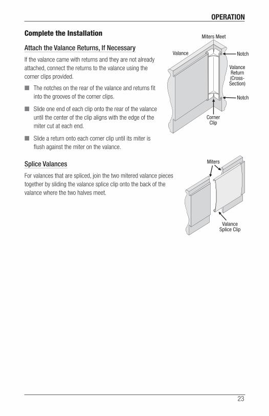
Attach the Valance Returns, If Necessary
If the valance came with returns and they are not already attached, connect the returns to the valance using the corner clips provided.
■ The notches on the rear of the valance and returns fit into the grooves of the corner clips.
■ Slide one end of each clip onto the rear of the valance until the center of the clip aligns with the edge of the miter cut at each end.
■ Slide a return onto each corner clip until its miter is flush against the miter on the valance.
Splice Valances
For valances that are spliced, join the two mitered valance pieces together by sliding the valance splice clip onto the back of the valance where the two halves meet.
Miters Meet
CornerClip
Valance
ValanceReturn(Cross-Section)
Notch
Notch
ValanceSplice Clip
Miters
OPERATION
24
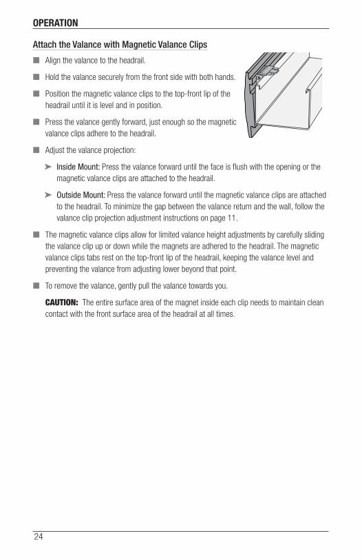
Attach the Valance with Magnetic Valance Clips
■ Align the valance to the headrail.
■ Hold the valance securely from the front side with both hands.
■ Position the magnetic valance clips to the top-front lip of the headrail until it is level and in position.
■ Press the valance gently forward, just enough so the magnetic valance clips adhere to the headrail.
■ Adjust the valance projection:
➤ Inside Mount: Press the valance forward until the face is flush with the opening or the magnetic valance clips are attached to the headrail.
➤ Outside Mount: Press the valance forward until the magnetic valance clips are attached to the headrail. To minimize the gap between the valance return and the wall, follow the valance clip projection adjustment instructions on page 11.
■ The magnetic valance clips allow for limited valance height adjustments by carefully sliding the valance clip up or down while the magnets are adhered to the headrail. The magnetic valance clips tabs rest on the top-front lip of the headrail, keeping the valance level and preventing the valance from adjusting lower beyond that point.
■ To remove the valance, gently pull the valance towards you.
CAUTION: The entire surface area of the magnet inside each clip needs to maintain clean contact with the front surface area of the headrail at all times.
OPERATION
25
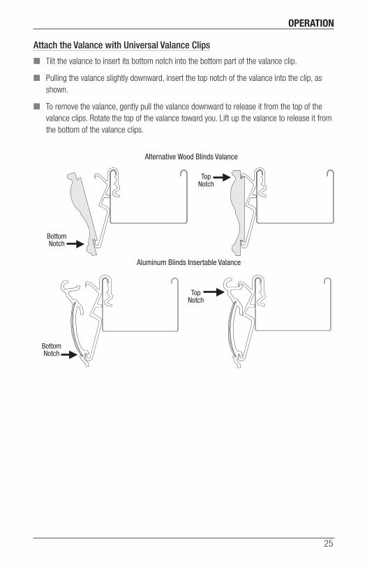
Attach the Valance with Universal Valance Clips
■ Tilt the valance to insert its bottom notch into the bottom part of the valance clip.
■ Pulling the valance slightly downward, insert the top notch of the valance into the clip, as shown.
■ To remove the valance, gently pull the valance downward to release it from the top of the valance clips. Rotate the top of the valance toward you. Lift up the valance to release it from the bottom of the valance clips.
BottomNotch
Alternative Wood Blinds Valance
Aluminum Blinds Insertable Valance
TopNotch
TopNotch
BottomNotch
OPERATION
26
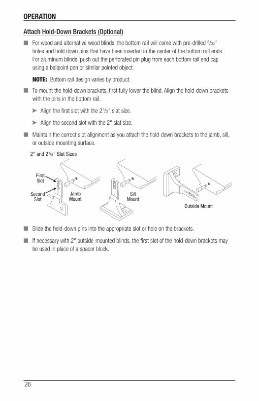
Attach Hold-Down Brackets (Optional)
■ For wood and alternative wood blinds, the bottom rail will come with pre-drilled 3/32" holes and hold down pins that have been inserted in the center of the bottom rail ends. For aluminum blinds, push out the perforated pin plug from each bottom rail end cap using a ballpoint pen or similar pointed object.
NOTE: Bottom rail design varies by product.
■ To mount the hold-down brackets, first fully lower the blind. Align the hold-down brackets with the pins in the bottom rail.
➤ Align the first slot with the 21/2" slat size.
➤ Align the second slot with the 2" slat size.
■ Maintain the correct slot alignment as you attach the hold-down brackets to the jamb, sill, or outside mounting surface.
■ Slide the hold-down pins into the appropriate slot or hole on the brackets.
■ If necessary with 2" outside-mounted blinds, the first slot of the hold-down brackets may be used in place of a spacer block.
JambMount
JambMount
SecondSlot
FirstSlot
SillMount
Outside Mount
Outside Mount
13/8" Slat Size
2" and 21/2" Slat Sizes
OPERATION
27
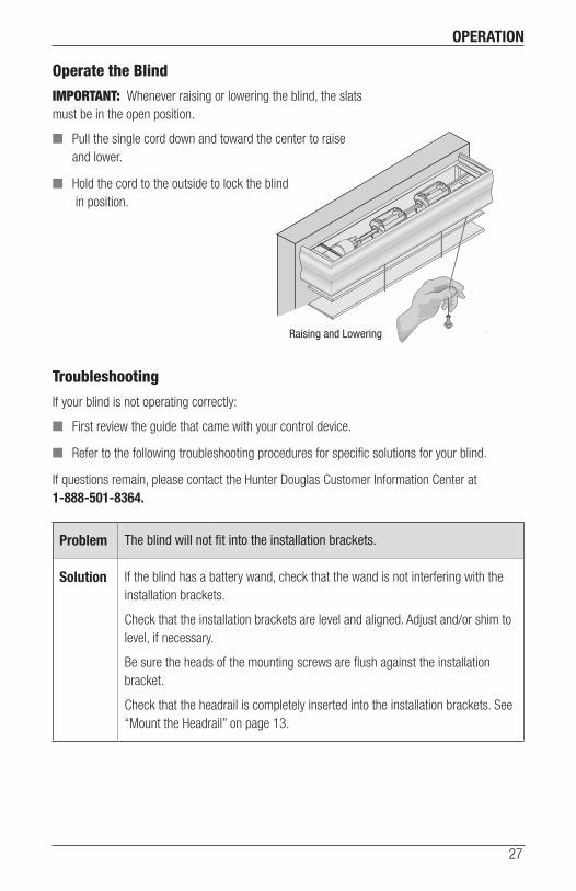
Operate the Blind
IMPORTANT: Whenever raising or lowering the blind, the slats must be in the open position.
■ Pull the single cord down and toward the center to raise and lower.
■ Hold the cord to the outside to lock the blind in position.
Troubleshooting
If your blind is not operating correctly:
■ First review the guide that came with your control device.
■ Refer to the following troubleshooting procedures for specific solutions for your blind.
If questions remain, please contact the Hunter Douglas Customer Information Center at 1-888-501-8364.
Problem The blind will not fit into the installation brackets.
Solution If the blind has a battery wand, check that the wand is not interfering with the installation brackets.
Check that the installation brackets are level and aligned. Adjust and/or shim to level, if necessary.
Be sure the heads of the mounting screws are flush against the installation bracket.
Check that the headrail is completely inserted into the installation brackets. See “Mount the Headrail” on page 13.
Raising and Lowering
OPERATION
28
Problem The blind does not operate using the manual control button.
Solution Unplug the power cable from the motor, then plug it back in. A green LED inside the manual control button housing should flash to indicate the motor has power.
Check that the batteries in the battery wand, satellite battery wand, or C-size satellite battery wand are correctly inserted and fresh.
Check that the battery wand, satellite battery wand, C-size satellite battery wand, or DC power supply is securely connected to the power cable and the cables are not pinched or caught in the headrail or installation brackets.
Problem The blind is not responding to the PowerView™ remote.
Solution IMPORTANT: A blind will not operate until it is joined to a group.
Check that the correct group number is selected.
Check that the batteries in the remote are correctly inserted and are fresh. The LEDs that backlight the remote should come on full bright when ■ STOP is pressed.
Problem The blind is operating slowly or does not tilt completely.
Solution The batteries may be low in the battery wand, satellite battery wand, or C-size battery wand. Replace the batteries.
Check that the battery wand, satellite battery wand, C-size satellite battery wand, or DC power supply is securely connected to the power cable and the cables are not pinched or caught in the headrail or installation brackets.
The blind may need to be reset. Refer to “Resetting the Blind (If Necessary)” on page 22.
Problem The LED light behind the manual control button of the transceiver assembly signals 8 red blinks.
Solution This is the low battery indicator. Replace the batteries in the battery wand.
CARE
29
Removing the Blind (If Necessary)
■ Fully raise the blind.
■ To remove the valance with magnetic valance clips, see page 24.
■ To remove the valance with universal valance clips, see page 25.
■ Push up on the bottom of the bracket to release the locking tab.
■ Carefully pull the blind to remove it from the brackets.
Cleaning Procedures
Like any fine furnishings, Hunter Douglas wood, alternative wood, and aluminum blinds should be cleaned regularly to keep them looking new.
Wood, Alternative Wood and Aluminum Blinds
■ Dust regularly. Use a soft clean cloth, chemically-treated dust cloth or dusting mitt. Lower the blind to its full length, tilt the slats almost all the way down and dust. Then tilt the slats almost all the way up and dust. (Not closing the slats all the way allows dusting where the slats overlap.)
■ Blinds may also be vacuumed. Use the brush attachment and tilt the slats up and down as described for dusting.
■ Another way to clean blinds is simply by wiping them with a soft, damp cloth.
Wood Blinds Only
■ Stained blinds, like wood furniture, should be treated periodically with lemon oil or other wood preservative to protect their finish and enhance their luster.
Alternative Wood and Aluminum Blinds
■ Wash the slats only using a non-abrasive mild detergent solution. Allow to air dry to preserve the dust repellent properties of the slats.
■ For a more thorough cleaning, metal or alternative wood bottom rails and slats may be immersed in a bathtub. Do not immerse headrails or wood bottom rails. Bathtub cleaning is not recommended for blinds with wide tapes.
IMPORTANT: Hunter Douglas does not recommend ultrasonic cleaning of wood, alternative wood, or aluminum blinds.
CHILD SAFETY
30
■ Young children can STRANGLE in cord loops. They can also wrap cords around their necks and STRANGLE. In addition, inner cords can pull out to form a loop, which can STRANGLE a young child.
■ Always keep cords out of the reach of children.
■ Move cribs, playpens and other furniture away from cords. Children can climb furniture to get to cords.
■ Do not tie cords together. Make sure cords do not twist together and create a loop.
Cord Connector
■ This component acts as a stopper to prevent inner cords from being pulled through the blind, which can pose the risk of entanglement.
■ It is also designed to break apart under significant pressure, which may lessen the risk of entanglement in the top lift cords.
Reassembly of Cord Connector
■ Reinsert any loose cords into the top notches of the cord connector. There is a notch on each side.
■ Line up the two halves of the cord connector and snap the pieces back together.
Cord Connector
FourCords
TwoCords
For more safety information call 1-888-501-8364 in the U.S. or 1-800-265-8000 in Canada.
WARNING

CHILD SAFETY
31
Cord Cleats
Hunter Douglas offers cord cleats and we recommend their use.
■ Attach two cord cleats 6" to 12" apart at a height where they will be out of the reach of children. Take into account that a child may stand on furniture attempting to reach the cords. Be sure the cleats are firmly secured.
■ Once the cleats are attached, wrap excess cord around them after each use of the blind.
NOTE: The warning labels on the bottom rails of corded blinds contain important safety information. These warning labels are designed to be permanent, in accordance with the industry’s safety standards, and must not be removed.

DECLARATIONS
32
U.S. Radio Frequency FCC ComplianceFCC ID information is located on top of the blind’s headrail.This device complies with Part 15 of the FCC Rules. Operation is subject to the following two conditions: (1) This device may not cause harmful interference, and (2) This device must accept any interference received, including interference that may cause undesired operation.This equipment has been tested and found to comply with the limits for a Class B digital device, pursuant to Part 15 of the FCC Rules. These limits are designed to provide reasonable protection against harmful interference in a residential installation. This equipment generates, uses and can radiate radio frequency energy and, if not installed and used in accordance with the instructions, may cause harmful interference to radio communications. However, there is no guarantee that interference will not occur in a particular installation. If this equipment does cause harmful interference to radio or television reception, which can be determined by turning the equipment off and on, the user is encouraged to try to correct the interference by one or more of the following measures:• Reorient or relocate the receiving antenna.• Increase the separation between the equipment and receiver.• Connect the equipment into an outlet on a circuit different from that to which the receiver is connected.• Consult the dealer or an experienced radio/TV technician for help.Any changes or modifications not expressly approved by the party responsible for compliance could void the user’s authority to operate the equipment.
Industry CanadaUnder Industry Canada regulations, this radio transmitter may only operate using an antenna of a type and maximum (or lesser) gain approved for the transmitter by Industry Canada. To reduce potential radio interference to other users, the antenna type and its gain should be so chosen that the equivalent isotropically radiated power (e.i.r.p.) is not more than that necessary for successful communication.This device complies with Industry Canada licence-exempt RSS standard(s). Operation is subject to the following two conditions: (1) this device may not cause interference, and (2) this device must accept any interference, including interference that may cause undesired operation of the device.Class B Digital Device Notice This Class B digital apparatus complies with Canadian ICES-003, RSS-Gen and RSS-210. CAN ICES-3 (B)/NMB-3(B)
European ConformityWe, the undersigned,Hunter Douglas Window Fashions One Duette Way, Broomfield, CO 80020, USAHunter Douglas Europe B.V. Piekstraat 2, 3071 EL Rotterdam, The Netherlandscertify and declare under our sole responsibility that assembly PV3 conforms with the essential requirements of the EMC directive 2004/108/EC and R&TTE directive 1999/5/EC.A copy of the original declaration of conformity may be found at: www.hunterdouglas.com/RFcertifications.


5130542001F 04/16
The Hunter Douglas® Lifetime Guarantee is an expression of our desire to provide a thoroughly satisfying experience when selecting, purchasing and living with your window fashion products. If you are not thoroughly satisfied, simply contact Hunter Douglas at (888) 501-8364 or visit hunterdouglas.com. In support of this policy of consumer satisfaction, we offer our Lifetime Limited Warranty as described below.
NOTE: In no event shall Hunter Douglas or its licensed fabricators/distributors be liable or responsible for incidental or consequential damages or for any other indirect damage, loss, cost or expense. Some states do not allow the exclusion or limitation of incidental or consequential damages, so the above exclusion or limitation may not apply to you. This warranty gives you specific legal rights, and you may also have other rights which vary from state to state.
Different warranty periods and terms apply for commercial products and applications.
Hunter Douglas (or its licensed fabricator/distributor) will repair or replace the window fashion product or components found to be defective.
COVEREDBY A LIFETIME LIMITED WARRANTY
• Hunter Douglas window fashion products are covered for defects in materials, workmanship or failure to operate for as long as the original retail purchaser owns the product (unless shorter periods are provided below).
• All internal mechanisms.
• Components and brackets.
• Fabric delamination.
• Operational cords for a full 7 years from the date of purchase.
• Repairs and/or replacements will be made with
like or similar parts or products.
• Hunter Douglas motorization components are covered for 5 years from the date of purchase.
NOT COVEREDBY A LIFETIME LIMITED WARRANTY
• Any conditions caused by normal wear and tear.
• Abuse, accidents, misuse or alterations to the product.
• Exposure to the elements (sun damage, wind, water/moisture) and discoloration or fading over time.
• Failure to follow our instructions with respect to measurement, proper installation, cleaning or maintenance.
• Shipping charges, cost of removal and reinstallation.
TO OBTAIN WARRANTY SERVICE
1. Contact your original dealer (place of purchase) for warranty assistance.
2. Visit hunterdouglas.com for additional warranty information, frequently asked questions and access to service locations.
3. Contact Hunter Douglas at (888) 501-8364 for technical support, certain parts free of charge, for assistance in obtainingwarranty service or for further explanation of our warranty.