installation & operation - bulk...
TRANSCRIPT

SSiillooPPaattrrooll® // FlexarFlexar®
Inventory Monitoring System
Installation & Operation ManualSoftware Programming Manual
SSiillooTTrraacckk™
Inventory Management SoftwareVersion 3.5X
B U L L E T I N
334444JJI N S T A L L A T I O N & O P E R A T I O N
In the event that information contained herein does not completely satisfy yourrequirements or answer your questions, you may contact Technical Support on ourwebsite www.monitortech.com, by telephone at 800-766-6486 (630-365-9403), orby fax at 630-365-5646. If your SMU or FlexarFlexar® ever requires service either in orout of warranty, please contact us and obtain an RMA number prior to shipping theunit to us.
®
SecureCareSM CUSTOMER SERVICEwww.monitortech.com/secure.shtml
(This bulletin is intended for use with an external USB RS-485 con-verter. If you are upgrading software and your RS-485 converter is
an internal device or you are using a converter not supplied byMonitor, please consult the factory for advice.)

22
ATTENTION:USE OF VOLUME & WEIGHT CALCULATIONS
The HMI2 and SiloTrack™ Inventory Management Software can performcalculations to display the volume and weight of material in each vessel.When utilizing this capability, the HMI2 or SiloTrack software will calculatethe volume and weight based upon the distance measurement made by theSMU, the vessel dimensions and the material bulk density entered duringsetup.
The calculated volume and weight values are effected by variations in actu-al vessel dimensions, angle of repose, fluctuation in material bulk densities,material flow properties (ratholes, bridging, etc.), vessel inlet/dischargelocation(s) and location of the sensor on the vessel. The direct distancemeasurement made by the SMU is from the bottom of the SMU mountingflange to the point on the plumb bob.
Prior to equipment installation, please consult the factory to discuss theapplication details if the volume/weight calculation are of critical importance.
1. Language Selection2. Introduction
2.1 SiloTrack™ Concepts2.2 Definitions
3. SiloPatrol® Network Configuration3.1 Network Connector Pin Assignment3.2 Connecting the RS-485 Communication Card(s)3.3 Ranges of Network/Configuration Addresses
4. Pre-Installation Considerations4.1 Minimum PC Requirements4.2 Physical Installation Specifications4.3 General Setup Procedures4.4 RS-485 Port Configuration
5. Installing SiloTrack Server6. Installing SiloTrack Client
TA B L E O F C O N T E N T S
33334444445556
11
7. Manual Server Software Program Setup7.1 Creating Silos7.2 Properties General Tab7.3 Relay Functions7.4 Enable Remote Access7.5 Security
8. Manual Client Software Program Setup9. Using SiloTrack
9.1 Relay Contact Indicators9.2 Alarm Indicators9.3 SiloTrack (SMU) Diagnostics9.4 Adding Pages9.5 History9.6 Automatic Reports
10. Reference Section11. Troubleshooting
11.1 System Errors11.2 Help Functions
131313131415151616161617171718191919
Section Page Section Page

33
L A N G U A G E S E L E C T I O N
This manual has been written to guide you toward a successfulSiloTrack™ installation. This programming manual is to be used inconjunction with Bulletins 344A (SMU Installation) and 344C (ifinstalling Auxiliary Output Enclosures), or 354A (FlexarFlexar® installa-tion) which are the hardware installation manuals for this family ofproducts.
The instructions contained within provide the essential stepsrequired in program set up achieving this goal. Most screens dur-ing program setup are self-explanatory. If you have a questionregarding any program step or entry during program setup, thecomprehensive help files that were installed on your PC duringinstallation will have the information you need to complete yourtask. If after consulting the help files you still have questions,please consult with the Technical Support staff at MonitorTechnologies LLC. We have even included a link to request customer service. This help function is located within the Help Tabof SiloTrack V3.5X on the main screen. Other technical support contact information can be found on the front cover of this document.
2.1 SiloTrack ConceptsWith the ever-growing Information Technology Boom, our cus-tomer base began to ask for material level measurement informa-tion to be available on their PC. We answered that request bydeveloping SiloTrack V1.0. Version 1.0 was a stand-alone pro-gram that only allows material level information to be viewed onone computer screen. Shortly after the release of V1.0 software,customers began asking for multi-user software so more than onePC could share and use the data. The nature of the requestsexpanded to include LAN (local area network) users, WAN (widearea network) users and Dial-Up users connecting by telephone.To accommodate these requests, we developed SiloTrack V2.01Server (or Host) and SiloTrack V2.01 Client (remote user) softwarepackages. The Server version resides on the PC that controls theSMUs (silo monitoring units) or FlexarFlexar® Guided Wave Radar.SMUs. measure the distance between the SMU mounting locationand the point on the material being measured at which the plumbbob impacts. FlexarFlexar’s measure the distance from the process con-nection to the point on the cable that intersects the material in yourtank or silo.
SiloTrack V2.01 Client version addressed the remote monitoringneeds by allowing multi point access to the silo measurement data-base. It has the ability to initiate a remote physical measurement ofmaterial in the event that the last measurement taken data is tooold to be satisfactory to the remote user. This version of softwarealso lends itself to aiding in Vendor Managed Inventory scenarios.Remote users or Clients can not access the Server or Host unlessthe Server software has been configured and password protectedto allow it. The current Version 3.5X further enhances SiloTrackfunctionality by the addition of a user-friendly Setup Wizard,expanded reporting capabilities, and will allow for multiple sensors(up to 5) on a single vessel to provide measurement averaging,and makes provision for FlexarFlexar® Guided Wave Radar.
No matter which communication method for Client access is cho-sen, secure communications are provided between the SiloTrackServer and any SiloTrack Client subscription. For networkedTCP/IP connections (LAN and WAN), a 56-bit encryption tech-nique is utilized to ensure that your data remains secure.Provisions are included to prohibit undesired IP addresses fromgaining access to SiloTrack Server during setup and theseaddresses can be added, deleted, or modified at any time. Dial-upsubscriptions between Server and Client are inherently secure ifthe telephone connection is hard wired. Additional dial-up securitycan be invoked by choosing the "Dial-Back" option during ClientSecurity setup. When this option is selected, the Client calls theServer through its dial-up connection. The Server acknowledgesthe connection request and terminates the Dial-up connection. TheServer then dials the Client back using a pre-configured telephonenumber thereby eliminating the possibility of someone trying togain access to SiloTrack from an unapproved location.
2.2 DefinitionsNetwork: SiloTrack will support up to eight networks. A network isdefined as a single RS-485 communications bus. Using SiloTrack,up to eight networks can be supported on a single PC that isappropriately configured with the necessary amount of RS-485ports. SiloTrack will support up to 16 SMUs per network. In addi-tion, each network will support up to a total of 4 accessorydevices consisting of Auxiliary Output Enclosures(AOEs) per network. SiloPatrol SMU’s and FlexarFlexar® Guided Wave Radarcan not coexist on the same RS485 network.
Node: Each SMU, on any common network, must have aunique sensor address. SiloTrack setup screens refer to thissensor address as a "node address." Specific instructions for set-ting the node address of each SMU may be found in Bulletin 344A.SiloTrack interprets the node address to be the value of the selec-tor switch in the SMU as described in Bulletin 344A where selectorswitch position 1 equals node 1, switch position A equals node 10,
Table 1: Example: 8 is the network # and 06 represents the SMU address. FlexarFlexar® uses ONLY decimal numbers.
To switch between the Primary and Alternatelanguage, from the main menu select File andSwitch Language.
I N T R O D U C T I O N
44
and switch position 0 equals node 16. There are 16 positions onthis switch and they must be set differently for each SMU that isconnected to the same network. Table 1 shows all possible SMUaddresses. FlexarFlexar addresses can be configured at the controlhead in parameter 1.6.2.NOTE: The default node address for every FlexarFlexar shipped is 1.Although SiloTrack is capable of changing node addressesthrough software, this is only possible if only one FlexarFlexar isconnected to a single RS.485 network at a time and poweredon.
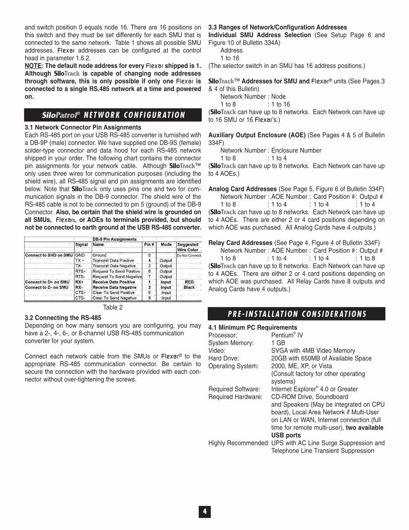
3.1 Network Connector Pin Assignments Each RS-485 port on your USB RS-485 converter is furnished witha DB-9P (male) connector. We have supplied one DB-9S (female)solder-type connector and data hood for each RS-485 networkshipped in your order. The following chart contains the connectorpin assignments for your network cable. Although SiloTrack™only uses three wires for communication purposes (including theshield wire), all RS-485 signal and pin assignments are identifiedbelow. Note that SiloTrack only uses pins one and two for com-munication signals in the DB-9 connector. The shield wire of theRS-485 cable is not to be connected to pin 5 (ground) of the DB-9Connector. Also, be certain that the shield wire is grounded onall SMUs, FlexarFlexarss , , or AOEs to terminals provided, but shouldnot be connected to earth ground at the USB RS-485 converter.
3.2 Connecting the RS-485 Depending on how many sensors you are configuring, you mayhave a 2-, 4-, 6-, or 8-channel USB RS-485 communication converter for your system.
Connect each network cable from the SMUs or FlexarFlexar® to theappropriate RS-485 communication connector. Be certain tosecure the connection with the hardware provided with each con-nector without over-tightening the screws.
Table 2
3.3 Ranges of Network/Configuration AddressesIndividual SMU Address Selection (See Setup Page 6 andFigure 10 of Bulletin 334A)
Address1 to 16
(The selector switch in an SMU has 16 address positions.)
SiloTrack™ Addresses for SMU and FlexarFlexar® units (See Pages 3& 4 of this Bulletin)
Network Number : Node1 to 8 : 1 to 16
(SiloTrack can have up to 8 networks. Each Network can have upto 16 SMU or 16 FlexarFlexar’s.)
Auxiliary Output Enclosure (AOE) (See Pages 4 & 5 of Bulletin334F)
Network Number : Enclosure Number1 to 8 : 1 to 4
(SiloTrack can have up to 8 networks. Each Network can have upto 4 AOEs.)
Analog Card Addresses (See Page 5, Figure 6 of Bulletin 334F)Network Number : AOE Number : Card Position #: Output #1 to 8 : 1 to 4 : 1 to 4 : 1 to 4
(SiloTrack can have up to 8 networks. Each Network can have upto 4 AOEs. There are either 2 or 4 card positions depending onwhich AOE was purchased. All Analog Cards have 4 outputs.)
Relay Card Addresses (See Page 4, Figure 4 of Bulletin 334F)Network Number : AOE Number : Card Position #: Output #1 to 8 : 1 to 4 : 1 to 4 : 1 to 8
(SiloTrack can have up to 8 networks. Each Network can have upto 4 AOEs. There are either 2 or 4 card positions depending onwhich AOE was purchased. All Relay Cards have 8 outputs andAnalog Cards have 4 outputs.)
4.1 Minimum PC RequirementsProcessor: Pentium® IVSystem Memory: 1 GBVideo: SVGA with 4MB Video MemoryHard Drive: 20GB with 650MB of Available SpaceOperating System: 2000, ME, XP, or Vista
(Consult factory for other operating systems)
Required Software: Internet Explorer® 4.0 or GreaterRequired Hardware: CD-ROM Drive, Soundboard
and Speakers (May be integrated on CPUboard), Local Area Network if Multi-User on LAN or WAN, Internet connection (full time for remote multi-user), two available USB ports
Highly Recommended: UPS with AC Line Surge Suppression andTelephone Line Transient Suppression
SiloPatrol® N E T W O R K C O N F I G U R AT I O N
P R E - I N S TA L L AT I O N C O N S I D E R AT I O N S
55
4.2 Physical Installation SpecificationsFor SMU SE installation, please refer to Installation & OperationBulletin 344A for complete details on wire specification and accept-able wiring practices. Please adhere to this document to ensure asuccessful installation. Not referenced in Bulletin 344A is the RS-485 interface connector schematic or "pin out" information, whichcan be found on page 4 of this manual. You will need this informa-tion to complete your cabling from your sensors to the RS-485communication port(s) on your converter. Bulletin 344C describesAOE installation. If installing FlexarFlexar®, use point to point (TrueDaisy-Chain) wiring without the use of any “T” junctions or multipledrops. For Flexar Flexar Guided Wave Radar, refer to Installation &Operation Bulletin 354A.
4.3 General Setup Procedures
1. Assemble your computer as instructed by the hardware manu-facturer in the desired location. Also at this time, install the USBSentinel Hardware Key that was supplied to you in a sealed envelope marked, "Security Key Enclosed. DO NOT DISCARD!" This key is to be installed in any available USB port.
2. Power on your system and verify its functionality. 3. Install the RS-485 communication software that was provided
with the USB RS-485 converter as instructed in the accompa-nying product literature. This software must be installed prior to connecting the USB RS-485 converter to your PC.
4. Please connect the RS-485 Network communication cable(s) from the sensors to the RS-485 Ports at this time. Again, remember that SiloPatrol® SMU and FlexarFlexar® cannot reside on the same RS-485 port.
5. Power on your PC. Apply power to the SMUs and/or FlexarFlexarss.
4.4 RS-485 Port Configuration
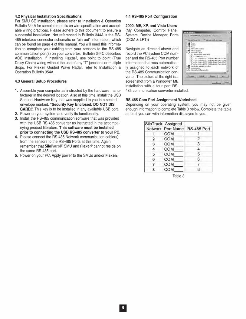
2000, ME, XP, and Vista Users (My Computer, Control Panel,System, Device Manager, Ports(COM & LPT))
Navigate as directed above andrecord the PC system COM num-ber and the RS-485 Port numberinformation that was automatical-ly assigned to each network ofthe RS-485 Communication con-verter. The picture at the right is ascreenshot from a Windows® MEinstallation with a four port RS-485 communication converter installed.
RS-485 Com Port Assignment WorksheetDepending on your operating system, you may not be givenenough information to complete Table 3 below. Complete the tableas best you can with information displayed to you.
Table 3

If you are upgrading from version 1.0, 2.XX, or 3.03 you must un-install the previous version before installing Version 3.5X. Previousdata files are not compatible with V3.5X so save your silo configu-ration data on hard copy before proceeding.
The following applies to both SiloTrack™ V3.5X Server andSiloTrack V3.5X Client. In the case of SiloTrack V3.5X Server, becertain the hardware security key has been inserted in anavailable USB port.
THE FOLLOWING IS EXTREMELY IMPORTANT IF SILOTRACKSERVER IS TO BE INSTALLED ON A PC WORKSTATION WITHMULTIPLE LOGINS.
During the installation process, you will be given a suggested datapath. The next paragraph indicates the preferred path structure. Itis recommended that the person installing SiloTrack Server belogged in as the Network Administrator.
Be certain that the data files created during installation be routedto the SiloTrack working directory and NOT to "My Documents."C:/Program Files/Monitor Technologies/SiloTrack3Server/ is thedefault destination path during installation. However, if your harddrive is partitioned, you may readily substitute Drive D for Drive Cby selecting Browse (when it appears on the installation screen)and make the change. This is normally done when it is desirable toisolate program files from system files for any reason. Consult yourIT manager for direction if in doubt.
Once the installation has finished, run the program and configureall the silos. If you do not have all the information at hand to con-figure all of the silos, configure at least one and then exit the pro-gram being certain that you save all the changes. Before loggingout of the PC Workstation, using a file pointer such as WindowsExplorer or by manually navigating to the above mentioned folder,right click on the folder and click on Properties. Navigate to the filesharing attributes and change the permissions to allow full controland access (read/write) to Everyone. Verify that the permissionsare indeed as described for the silotrackdata.st3 file AND the silo-track3.mdb file. Copy both of these files to a secure location, otherthan the SiloTrack Server working directory, should a SiloTrackrecovery ever become necessary for any reason. Update thesebackup files on a regular basis so that your inventory history datais fairly recent as well as silo setup data. Any time you make silosetup changes, exit the SiloTrack Server program and update yourbacked-up copies. It is imperative that SiloTrack is not running dur-ing the back up process.
66
I N S TA L L I N G SiloTrack™ S E RV E R
Continue the installation by clicking Next.
Although it is possible to have 16 silo icons on a single page, Itmay be desirous to organize groups of silos on individual pages.To do so, you would simple enter a name for a new page in thePage Name box and click on the Add key. Pages can be added,deleted, or renamed manually at a later time if desired. Once youhave entered additional page names or you only need one page,click on Next to continue installation and the following screen willappear.
Insert the appropriate SiloTrack CD-ROM into you CD drive. Youroperating system will query the CD and The InstallShield Wizardwill run. If the CD does not automatically run, click on Start, Run,and click on Browse. A window will open that will allow you toidentify and select the appropriate drive letter for your CD-ROM.Do so. Then, you will see a setup icon. Left click on the setup iconand then click on Open.
When the Wizard completes installation, click on Finish to exit fromthe installation software. During the installation, a SiloTrack iconwas placed on your desktop. Click on it and the following screenwill appear.
77
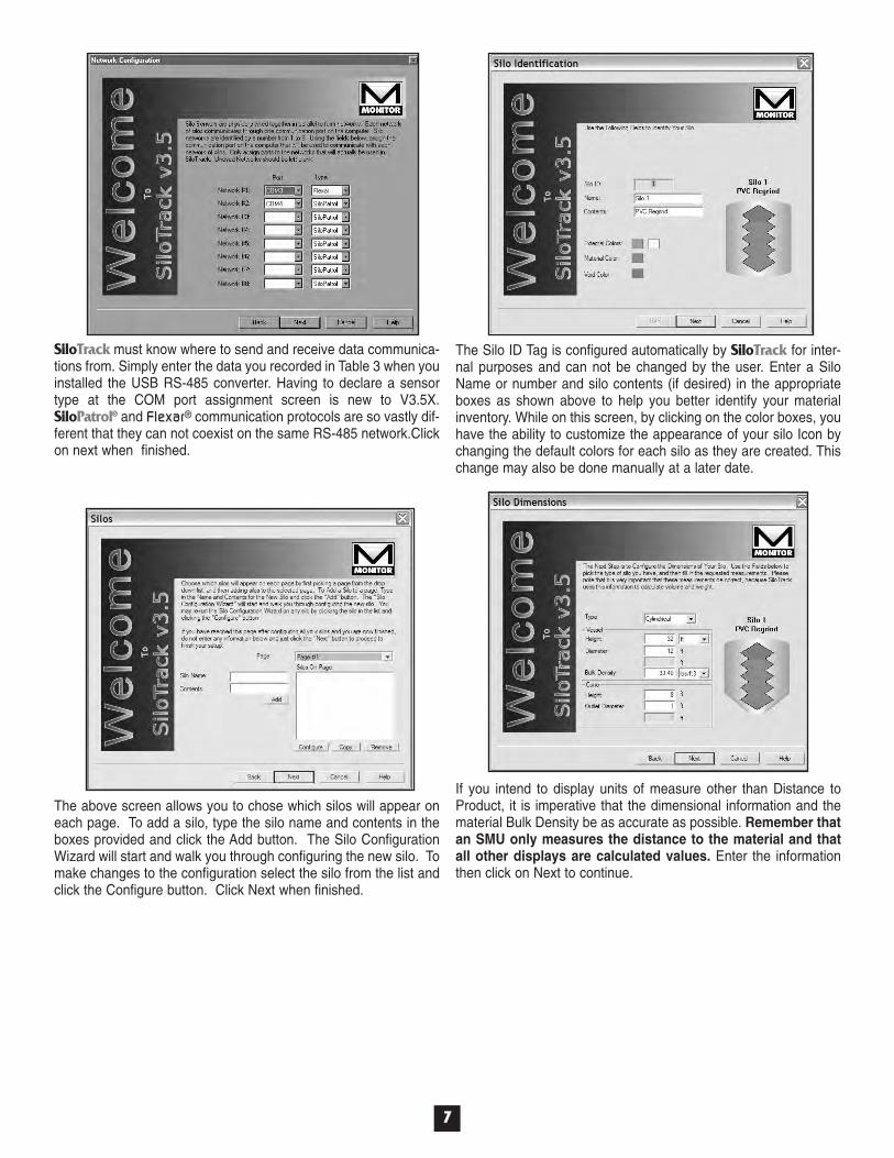
SiloTrack must know where to send and receive data communica-tions from. Simply enter the data you recorded in Table 3 when youinstalled the USB RS-485 converter. Having to declare a sensortype at the COM port assignment screen is new to V3.5X.SiloPatrol® and FlexarFlexar® communication protocols are so vastly dif-ferent that they can not coexist on the same RS-485 network.Clickon next when finished.
The Silo ID Tag is configured automatically by SiloTrack for inter-nal purposes and can not be changed by the user. Enter a SiloName or number and silo contents (if desired) in the appropriateboxes as shown above to help you better identify your materialinventory. While on this screen, by clicking on the color boxes, youhave the ability to customize the appearance of your silo Icon bychanging the default colors for each silo as they are created. Thischange may also be done manually at a later date.
If you intend to display units of measure other than Distance toProduct, it is imperative that the dimensional information and thematerial Bulk Density be as accurate as possible. Remember thatan SMU only measures the distance to the material and thatall other displays are calculated values. Enter the informationthen click on Next to continue.
The above screen allows you to chose which silos will appear oneach page. To add a silo, type the silo name and contents in theboxes provided and click the Add button. The Silo ConfigurationWizard will start and walk you through configuring the new silo. Tomake changes to the configuration select the silo from the list andclick the Configure button. Click Next when finished.
88
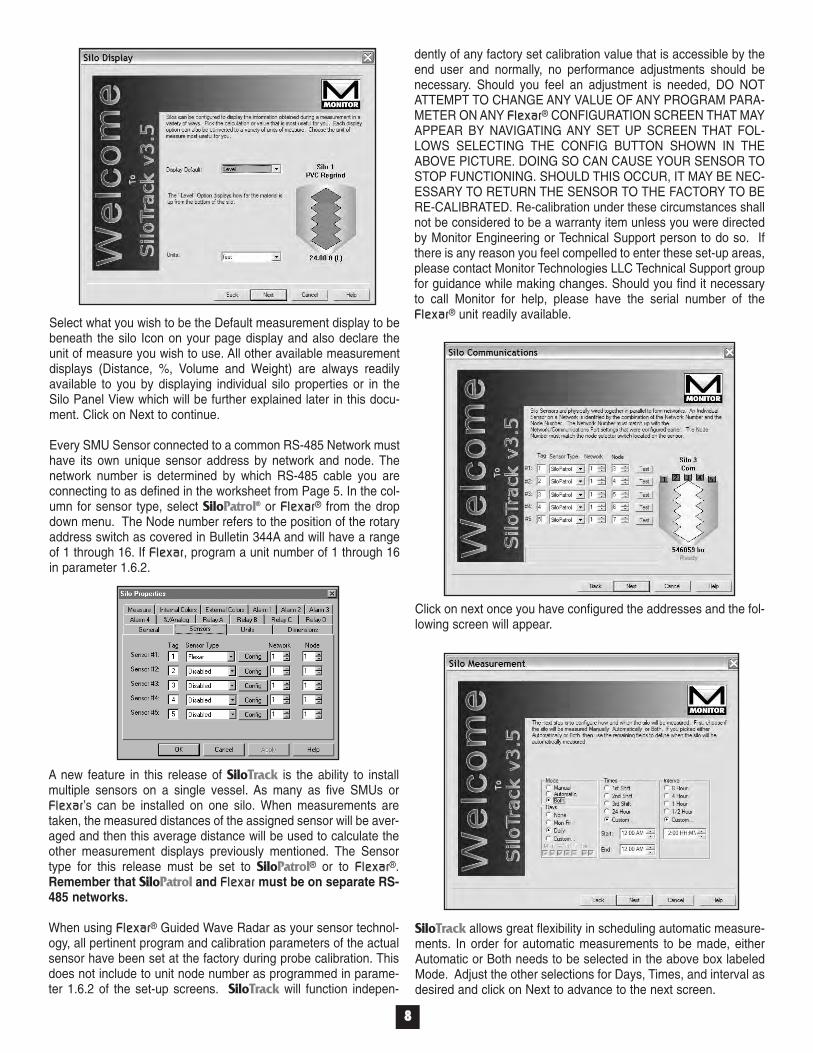
SiloTrack allows great flexibility in scheduling automatic measure-ments. In order for automatic measurements to be made, eitherAutomatic or Both needs to be selected in the above box labeledMode. Adjust the other selections for Days, Times, and interval asdesired and click on Next to advance to the next screen.
Click on next once you have configured the addresses and the fol-lowing screen will appear.
A new feature in this release of SiloTrack is the ability to installmultiple sensors on a single vessel. As many as five SMUs orFlexarFlexar’s can be installed on one silo. When measurements aretaken, the measured distances of the assigned sensor will be aver-aged and then this average distance will be used to calculate theother measurement displays previously mentioned. The Sensortype for this release must be set to SiloPatrol® or to FlexarFlexar®.Remember that SiloPatrol and FlexarFlexar must be on separate RS-485 networks.
When using FlexarFlexar® Guided Wave Radar as your sensor technol-ogy, all pertinent program and calibration parameters of the actualsensor have been set at the factory during probe calibration. Thisdoes not include to unit node number as programmed in parame-ter 1.6.2 of the set-up screens. SiloTrack will function indepen-
Select what you wish to be the Default measurement display to bebeneath the silo Icon on your page display and also declare theunit of measure you wish to use. All other available measurementdisplays (Distance, %, Volume and Weight) are always readilyavailable to you by displaying individual silo properties or in theSilo Panel View which will be further explained later in this docu-ment. Click on Next to continue.
Every SMU Sensor connected to a common RS-485 Network musthave its own unique sensor address by network and node. Thenetwork number is determined by which RS-485 cable you areconnecting to as defined in the worksheet from Page 5. In the col-umn for sensor type, select SiloPatrol® or FlexarFlexar® from the dropdown menu. The Node number refers to the position of the rotaryaddress switch as covered in Bulletin 344A and will have a rangeof 1 through 16. If FlexarFlexar, program a unit number of 1 through 16in parameter 1.6.2.
dently of any factory set calibration value that is accessible by theend user and normally, no performance adjustments should benecessary. Should you feel an adjustment is needed, DO NOTATTEMPT TO CHANGE ANY VALUE OF ANY PROGRAM PARA-METER ON ANY FlexarFlexar® CONFIGURATION SCREEN THAT MAYAPPEAR BY NAVIGATING ANY SET UP SCREEN THAT FOL-LOWS SELECTING THE CONFIG BUTTON SHOWN IN THEABOVE PICTURE. DOING SO CAN CAUSE YOUR SENSOR TOSTOP FUNCTIONING. SHOULD THIS OCCUR, IT MAY BE NEC-ESSARY TO RETURN THE SENSOR TO THE FACTORY TO BERE-CALIBRATED. Re-calibration under these circumstances shallnot be considered to be a warranty item unless you were directedby Monitor Engineering or Technical Support person to do so. Ifthere is any reason you feel compelled to enter these set-up areas,please contact Monitor Technologies LLC Technical Support groupfor guidance while making changes. Should you find it necessaryto call Monitor for help, please have the serial number of theFlexarFlexar® unit readily available.
99
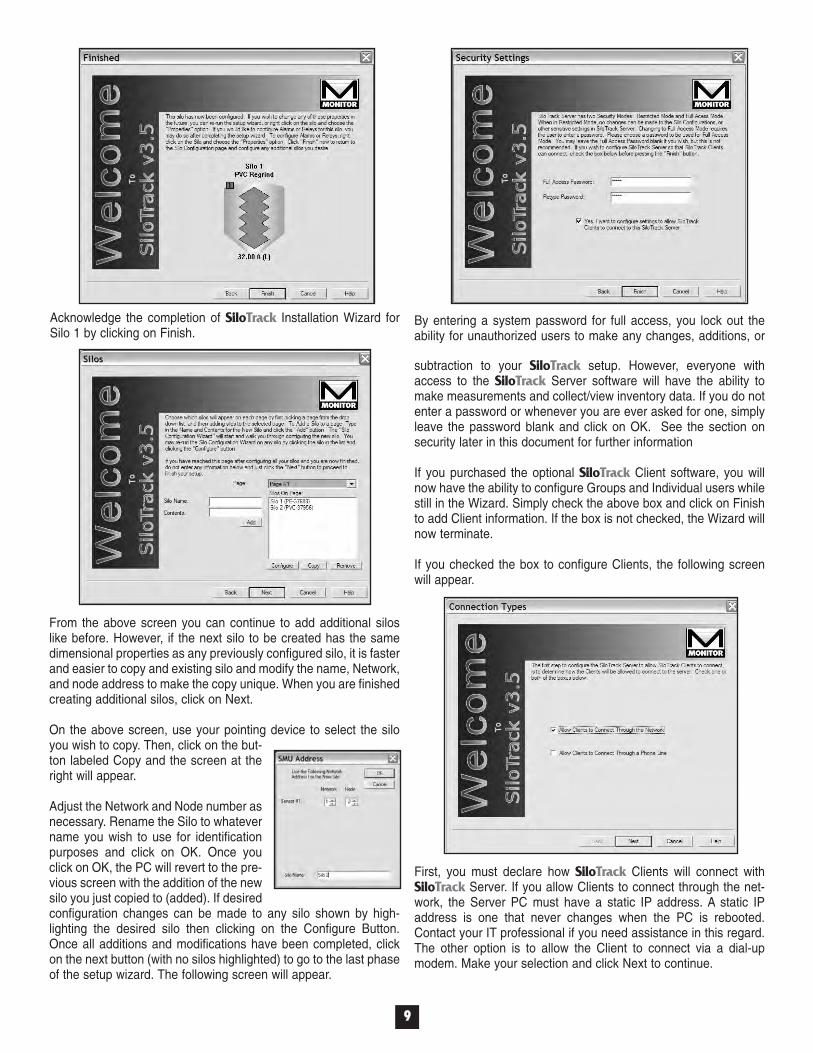
Acknowledge the completion of SiloTrack Installation Wizard forSilo 1 by clicking on Finish.
From the above screen you can continue to add additional siloslike before. However, if the next silo to be created has the samedimensional properties as any previously configured silo, it is fasterand easier to copy and existing silo and modify the name, Network,and node address to make the copy unique. When you are finishedcreating additional silos, click on Next.
On the above screen, use your pointing device to select the siloyou wish to copy. Then, click on the but-ton labeled Copy and the screen at theright will appear.
Adjust the Network and Node number asnecessary. Rename the Silo to whatevername you wish to use for identificationpurposes and click on OK. Once youclick on OK, the PC will revert to the pre-vious screen with the addition of the newsilo you just copied to (added). If desiredconfiguration changes can be made to any silo shown by high-lighting the desired silo then clicking on the Configure Button.Once all additions and modifications have been completed, clickon the next button (with no silos highlighted) to go to the last phaseof the setup wizard. The following screen will appear.
By entering a system password for full access, you lock out theability for unauthorized users to make any changes, additions, or
subtraction to your SiloTrack setup. However, everyone withaccess to the SiloTrack Server software will have the ability tomake measurements and collect/view inventory data. If you do notenter a password or whenever you are ever asked for one, simplyleave the password blank and click on OK. See the section onsecurity later in this document for further information
If you purchased the optional SiloTrack Client software, you willnow have the ability to configure Groups and Individual users whilestill in the Wizard. Simply check the above box and click on Finishto add Client information. If the box is not checked, the Wizard willnow terminate.
If you checked the box to configure Clients, the following screenwill appear.
First, you must declare how SiloTrack Clients will connect withSiloTrack Server. If you allow Clients to connect through the net-work, the Server PC must have a static IP address. A static IPaddress is one that never changes when the PC is rebooted.Contact your IT professional if you need assistance in this regard.The other option is to allow the Client to connect via a dial-upmodem. Make your selection and click Next to continue.

1100
Permissions to view silo measurement information has to be grant-ed to both Groups and/or Users. Once the administrator has grant-ed permissions, determine if the Client is to be allowed to initiate ameasurement from his or her own PC. The status of Read-Onlyequals “Yes” must be changed to “No” on a silo-by-silo basis inorder to do so.
If you ever get this error onyour screen (See imageright), it is because you failedto highlight a name to grantpermissions to.
This is where the Wizardends. Alarms and all auxiliary output options (if so equipped) mustbe done manually as described later in this document. It would bea good idea to close SiloTrack to save all data to disk. The nexttime you run the SiloTrack program it will start in the restrictedaccess mode. So if you need to modify anything select Security,Full Access, enter your password when prompted, and click OK.Then you will have full editing capabilities.
Users must be added and configured. To add a user, press theAdd button. The Edit button allows you to make changes to anexisting user. To configure Silo Permissions for the user use thePermissions button. The user will inherit permissions from thegroups he or she belongs to, so you may not need to configure SiloPermissions on an individual basis. Click Next when finished.
The easiest way to manage users is to establish Groups. By set-ting up Groups you can assign permissions to several users atonce instead of on a individual basis. Type the Group name intothe box and click the Add button. Once you have finished creatingGroups, click on Next to continue.
After defining Group names, ifused, you must now identify indi-vidual Users and assign them apassword. This user name andpassword are required for theClient software to connect. In thisscreen, you can also assign theuser to a Group by clicking theAdd button. Click OK when fin-ished.
For improved security SiloTrack Server goes beyond a user nameand password. In this screen, Server can be configured to enforcesecurity at the hardware level. To allow only certain computers toconnect to SiloTrack Server select the “Allow Clients to ConnectONLY From THESE Computers” option. Fill in the Clients’ static(NOT dynamic) IP addresses in the box. If you need additionalhelp with this feature, please contact your IT professional or referto Allow/Deny lists in the SiloTrack help system.
1111
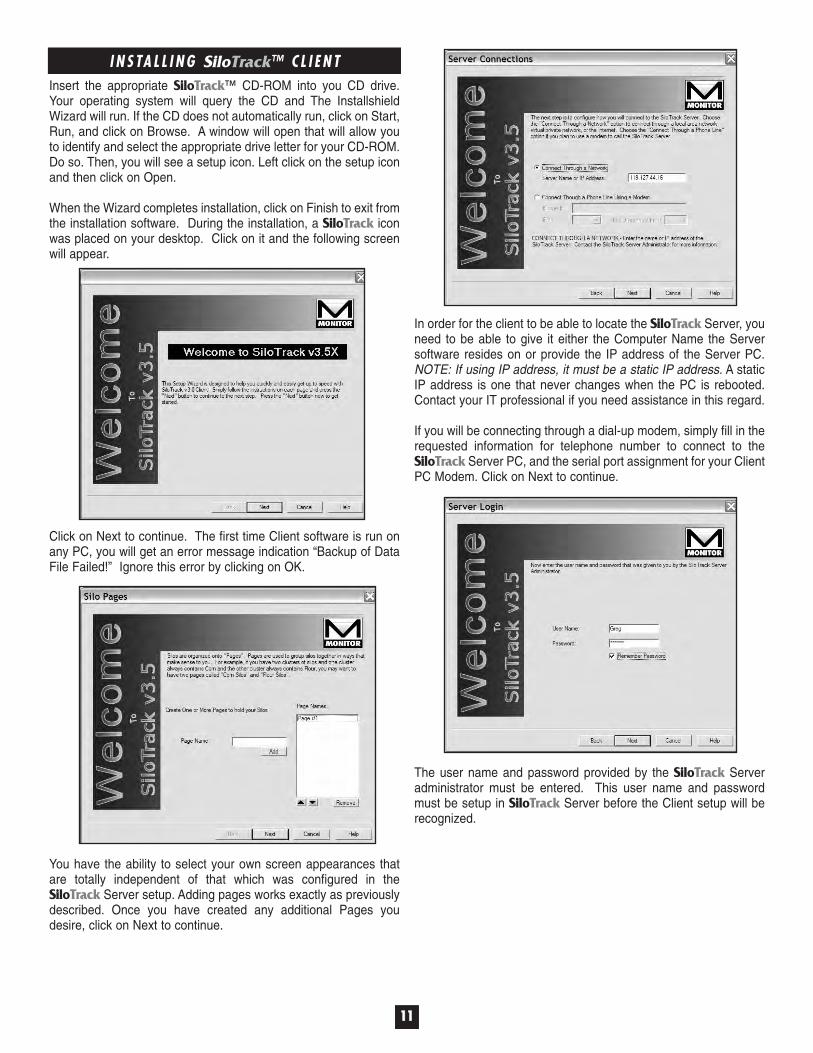
I N S TA L L I N G SiloTrack™ C L I E N TInsert the appropriate SiloTrack™ CD-ROM into you CD drive.Your operating system will query the CD and The InstallshieldWizard will run. If the CD does not automatically run, click on Start,Run, and click on Browse. A window will open that will allow youto identify and select the appropriate drive letter for your CD-ROM.Do so. Then, you will see a setup icon. Left click on the setup iconand then click on Open.
When the Wizard completes installation, click on Finish to exit fromthe installation software. During the installation, a SiloTrack iconwas placed on your desktop. Click on it and the following screenwill appear.
Click on Next to continue. The first time Client software is run onany PC, you will get an error message indication “Backup of DataFile Failed!” Ignore this error by clicking on OK.
You have the ability to select your own screen appearances thatare totally independent of that which was configured in theSiloTrack Server setup. Adding pages works exactly as previouslydescribed. Once you have created any additional Pages youdesire, click on Next to continue.
In order for the client to be able to locate the SiloTrack Server, youneed to be able to give it either the Computer Name the Serversoftware resides on or provide the IP address of the Server PC.NOTE: If using IP address, it must be a static IP address. A staticIP address is one that never changes when the PC is rebooted.Contact your IT professional if you need assistance in this regard.
If you will be connecting through a dial-up modem, simply fill in therequested information for telephone number to connect to theSiloTrack Server PC, and the serial port assignment for your ClientPC Modem. Click on Next to continue.
The user name and password provided by the SiloTrack Serveradministrator must be entered. This user name and passwordmust be setup in SiloTrack Server before the Client setup will berecognized.
1122
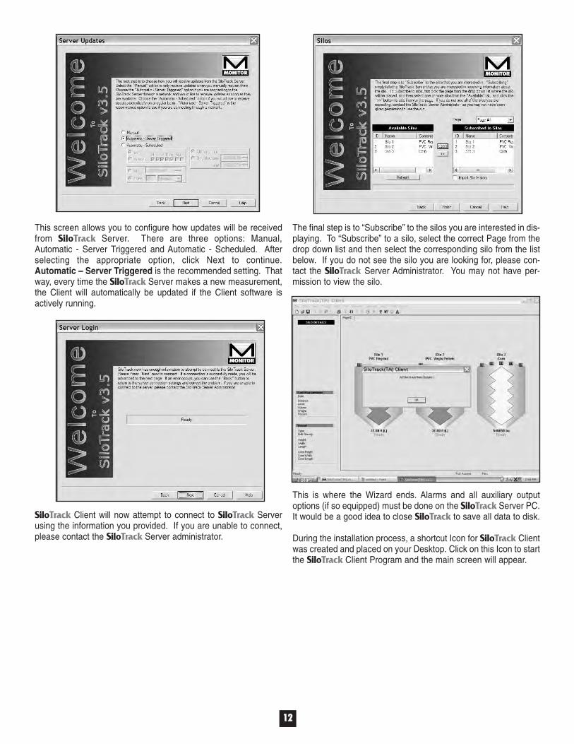
The final step is to “Subscribe” to the silos you are interested in dis-playing. To “Subscribe” to a silo, select the correct Page from thedrop down list and then select the corresponding silo from the listbelow. If you do not see the silo you are looking for, please con-tact the SiloTrack Server Administrator. You may not have per-mission to view the silo.
This is where the Wizard ends. Alarms and all auxiliary outputoptions (if so equipped) must be done on the SiloTrack Server PC.It would be a good idea to close SiloTrack to save all data to disk.
During the installation process, a shortcut Icon for SiloTrack Clientwas created and placed on your Desktop. Click on this Icon to startthe SiloTrack Client Program and the main screen will appear.
SiloTrack Client will now attempt to connect to SiloTrack Serverusing the information you provided. If you are unable to connect,please contact the SiloTrack Server administrator.
This screen allows you to configure how updates will be receivedfrom SiloTrack Server. There are three options: Manual,Automatic - Server Triggered and Automatic - Scheduled. Afterselecting the appropriate option, click Next to continue.Automatic – Server Triggered is the recommended setting. Thatway, every time the SiloTrack Server makes a new measurement,the Client will automatically be updated if the Client software isactively running.

7.1 Creating Silos(Silo – Add Silo)
NOTE: At the default icon size, asshown, you will be able to fit 16 siloicons on a single page if your videoresolution is sufficiently high.Instructions on adding screenpages will be described in a latersection of this manual. As silos areadded, the icons will automaticallyresize and reposition.
M A N U A L S E RV E R S O F T WA R E P R O G R A M S E T U PUpon software installation, if you closed the Installation Wizardwithout entering vessel and material parameters, you will eitherhave to run the Wizard again or you can manually program vesseland material information as follows.
Before configuring any other fea-ture of SiloTrack™, on the mainscreen, click on Config and then onNetworks. Left clicking onNetworks will cause the windowshown below right to open. Enter inthe COM port information asdescribed earlier in this documentdepending upon your operatingsystem. Once you have completedall applicable COM entries forNetwork assignments, click on OK.Again, left click on Config and the dropdown window will again open.Complete system setup, Fax setup, E-mail setup, and Pager setup if you aregoing to use these features.
NOTE 1: If you are using Monitor’s 6-8001 Serial RS-232 to RS-485Converter, enter the serial Com Portyou will connect to. This will most like-ly be COM 1 or COM 2.
NOTE 2: Having to declare a sensor type at the COM port assign-ment screen is new to V3.5X. SiloPatrol® and FlexarFlexar® communi-cation protocols are so vastly different that they can not coexist onthe same RS-485 network.
1133
Next, right click on the Silo imagethat was just created and a dropdown menu screen will appear.
Click on Properties and the screen below will appear.
At the top of the screen, left click on Security and then click on FullAccess. An Enter Password window will open. Leave the passwordblank and click OK unless you entered a password in the setupWizard.
7.2 Properties General Tab(Silo – Properties – General)Note: Whatever you choose for Display Default is what will be usedto determine alarm set points. All other Tabs shown at the left areself-explanatory in terms of what information needs to be entered.If you need additional information, please consult the comprehen-sive help files by clicking on the Help button.
7.3 Relay FunctionsIf you do not have theoptional Auxiliary OutputEnclosures, Section 7.3does not apply.
Disabled: Selecting Dis-abled in the function col-umn disables all relay func-tion and prohibits relay con-tact from closing.
1144
Decide if you want to use Dial-Back Security and set this optionaccordingly. Dial-Back security receives an access request from aremote dial-up user, hangs up the phone line, and then dials a pre-programmed phone number.This prevents remote usersfrom gaining access fromlocations other than what isprogrammed.
Silo must be selected orhighlighted to see if ReadOnly is selected or not.
If you choose to EnforceTCP/IP Security, Determinethe Name or IP Addressof the client computer.
When Configuring TCP/IP communication in conjunction withSiloTrack programming, it is important to know if your IP addressis subject to change. If SiloTrack Server resides on a PC on anInternal Local Area Network (LAN), you should have an IP addressfor internal communication that remains at a constant value. This“fixed” value is referred to as a Static IP Address. If you are con-necting through a Wide Area Network (WAN) via the Internet, youmost likely have an Internet IP address that changes (althoughslightly) every time you connect. A changing IP address is calleda Dynamic IP Address. Most Internet Service Providers have thecapability, usually for an additional monthly fee, of providing youwith a Static IP Address, if desired.
A typical IP address might look something like this: 199.125.55.69.In the example shown, there are four different number fields sepa-rated by decimals that define the address. If you have a DynamicIP Address, you can contact your service provider to determine the“range” of IP addresses you can expect to see. Using the aboveaddress as a reference, your ISP may inform you that the first twofields will always remain constant, but the last two will vary witheach new connection. If you enter the IP address in the TCP/IPsetup of Client Security of the SiloTrack Server software as199.128. (omitting the remaining two fields), anyone attempting toconnect with an IP address beginning with the first two fields wouldbe allowed access no matter what values are in fields three andfour. (Access will only be granted if their User Name andPassword match what was entered during setup of the SiloTrackServer software.)
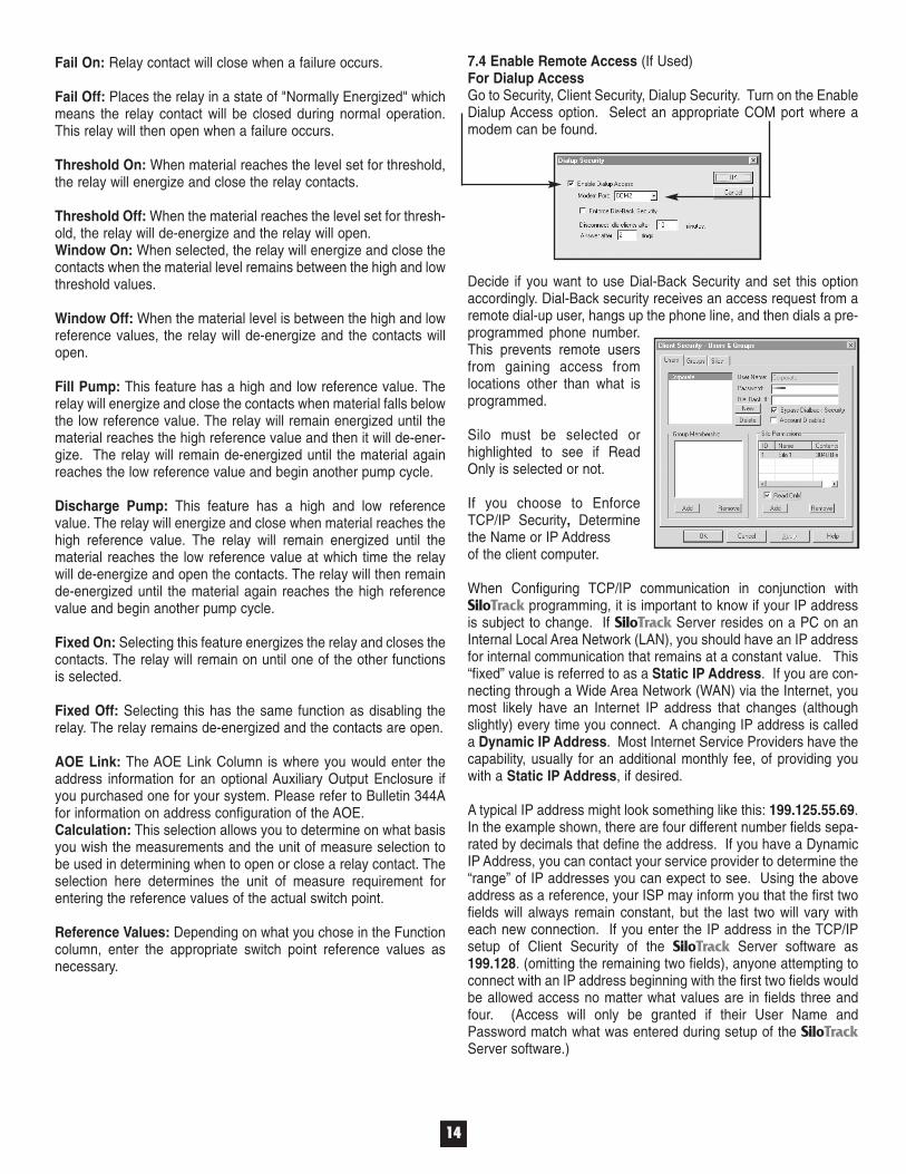
7.4 Enable Remote Access (If Used)For Dialup AccessGo to Security, Client Security, Dialup Security. Turn on the EnableDialup Access option. Select an appropriate COM port where amodem can be found.
Fail On: Relay contact will close when a failure occurs.
Fail Off: Places the relay in a state of "Normally Energized" whichmeans the relay contact will be closed during normal operation.This relay will then open when a failure occurs.
Threshold On: When material reaches the level set for threshold,the relay will energize and close the relay contacts.
Threshold Off: When the material reaches the level set for thresh-old, the relay will de-energize and the relay will open. Window On: When selected, the relay will energize and close thecontacts when the material level remains between the high and lowthreshold values.
Window Off: When the material level is between the high and lowreference values, the relay will de-energize and the contacts willopen.
Fill Pump: This feature has a high and low reference value. Therelay will energize and close the contacts when material falls belowthe low reference value. The relay will remain energized until thematerial reaches the high reference value and then it will de-ener-gize. The relay will remain de-energized until the material againreaches the low reference value and begin another pump cycle.
Discharge Pump: This feature has a high and low referencevalue. The relay will energize and close when material reaches thehigh reference value. The relay will remain energized until thematerial reaches the low reference value at which time the relaywill de-energize and open the contacts. The relay will then remainde-energized until the material again reaches the high referencevalue and begin another pump cycle.
Fixed On: Selecting this feature energizes the relay and closes thecontacts. The relay will remain on until one of the other functionsis selected.
Fixed Off: Selecting this has the same function as disabling therelay. The relay remains de-energized and the contacts are open.
AOE Link: The AOE Link Column is where you would enter theaddress information for an optional Auxiliary Output Enclosure ifyou purchased one for your system. Please refer to Bulletin 344Afor information on address configuration of the AOE.Calculation: This selection allows you to determine on what basisyou wish the measurements and the unit of measure selection tobe used in determining when to open or close a relay contact. Theselection here determines the unit of measure requirement forentering the reference values of the actual switch point.
Reference Values: Depending on what you chose in the Functioncolumn, enter the appropriate switch point reference values asnecessary.

For TCP/IP Access (Ethernet)Go to Security Client Security TCP/IP Security and enter The IPAddresses of each Client you wish to allow access to SiloTrack. Ifyou do not know the IP Address, contact your system administra-tor. Repeat the procedure for any IP Address or Address Rangeyou wish to specifically Deny access to in the lower box.
If access is granted outsideyour internal LAN, it isstrongly recommended thatthe Enforce TCP/IPSecurity Box be checkedat all times. Selecting thisoption prohibits TCP/IPaccess from any IP addressother than those included inthe Allow list. Type theclient computer Name or IPAddress in the box abovethe Add button in the "Allow These Hosts/IP Addresses to Connect"section. Click the Add button to add the client to the allow list.Click OK.
Next, create a Client User Name and Password. Beginning fromthe Tool Bar, Choose Security, Client Security, Users and Groups. Select the Users tab if necessary. Click the New button. Type anew user name and click OK.
1155
Next, type a User’s passwordin the password field.
If you are using Dial-BackSecurity, enter a dial-backnumber. Click the Add but-ton under the "SiloPermissions" section.
Choose one or more silosand click OK. If you arechoosing more than one silo,click on the first silo you wishto add to select it. Multiplesilos can be selected by pressing and holding the control key whileclicking on the additional silos before clicking on OK. The newuser will be granted read-only access to the selected silos.
Automatic - Server Triggered: When this option is selected, each time the Server software has a new measurement or other event, the server will automatically update the Client Data screen. Manual: Requires the user to select UPDATE or UPDATE ALL from the SILO menu in order to receive the latest silo levelinformation.Automatic - Scheduled: Provides scheduled silo data updatesas a function of time and day.
7. Click OK.8. Click the Silo
Subscriptions but-ton on the toolbar, orchoose Silo Add. The Silo Subscription Button is the picture of a Silo with a "+" on it.
9. At this point the SiloTrack V3.5X Client will attempt to contact the SiloTrack V3.5X Server and login. If successful, you will bepresented with a Silo Subscriptions box from which you may choose one or more silos to subscribe to. If the connection fails,check the Comm Log on both the Client and Server for infor-mation, check the Password, and check spelling of the User Name.
If you want the client to be able to measure the silos, click one ormore silos in the list and uncheck the Read-Only box. The statusof the "Read Only" box is only visible when the silo in question ishighlighted. Click OK. Click the Save button on the toolbar to saveall configuration changes. Make sure the phone line and/or net-work cable is connected to the SiloTrack V3.5X Server computer.
7.5 SecurityWHEN ALL PROGRAMMING HAS BEEN COMPLETED, CLICKON SECURITY. CHANGE THE SiloTrack PASSWORD TO PRE-VENT YOUR PARAMETERS FROM BEING INADVERTENTLYCHANGED OR DELETED. THEN SELECT RESTRICTEDACCESS. Doing so will limit the functionality of SiloTrack so thatthe operator can only take measurements and display measure-ment data. Be sure to record your password and store it in a safeplace. Only trusted key personnel should be allowed full-unre-stricted access to your SiloTrack programming functions.
1. Start the SiloTrack™ V3.5X Client software2. Change to Full Security Level (See above).3. Click the New button on the toolbar, or choose File New.4. Choose a Connection Type.5. Type in your Login Information.6. Choose an Update Type.
M A N U A L C L I E N T S O F T WA R E P R O G R A M S E T U P
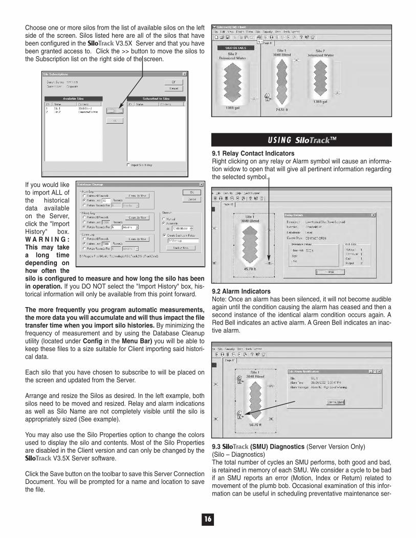
9.1 Relay Contact IndicatorsRight clicking on any relay or Alarm symbol will cause an informa-tion widow to open that will give all pertinent information regardingthe selected symbol.
U S I N G SiloTrack™
9.2 Alarm IndicatorsNote: Once an alarm has been silenced, it will not become audibleagain until the condition causing the alarm has ceased and then asecond instance of the identical alarm condition occurs again. ARed Bell indicates an active alarm. A Green Bell indicates an inac-tive alarm.
9.3 SiloTrack (SMU) Diagnostics (Server Version Only)(Silo – Diagnostics)The total number of cycles an SMU performs, both good and bad,is retained in memory of each SMU. We consider a cycle to be badif an SMU reports an error (Motion, Index or Return) related tomovement of the plumb bob. Occasional examination of this infor-mation can be useful in scheduling preventative maintenance ser-
1166
If you would liketo import ALL ofthe historicaldata availableon the Server,click the "ImportHistory" box.W A R N I N G :This may takea long timedepending onhow often thesilo is configured to measure and how long the silo has beenin operation. If you DO NOT select the "Import History" box, his-torical information will only be available from this point forward.
The more frequently you program automatic measurements,the more data you will accumulate and will thus impact the filetransfer time when you import silo histories. By minimizing thefrequency of measurement and by using the Database Cleanuputility (located under Config in the Menu Bar) you will be able tokeep these files to a size suitable for Client importing said histori-cal data.
Each silo that you have chosen to subscribe to will be placed onthe screen and updated from the Server.
Arrange and resize the Silos as desired. In the left example, bothsilos need to be moved and resized. Relay and alarm indicationsas well as Silo Name are not completely visible until the silo isappropriately sized (See example).
You may also use the Silo Properties option to change the colorsused to display the silo and contents. Most of the Silo Propertiesare disabled in the Client version and can only be changed by theSiloTrack V3.5X Server software.
Click the Save button on the toolbar to save this Server ConnectionDocument. You will be prompted for a name and location to savethe file.
Choose one or more silos from the list of available silos on the leftside of the screen. Silos listed here are all of the silos that havebeen configured in the SiloTrack V3.5X Server and that you havebeen granted access to. Click the >> button to move the silos tothe Subscription list on the right side of the screen.

1177
vice for each individual SMU. These numbers are accumulativeand can not be reset by the user. A high ratio of good to bad cyclesindicates smooth functionality. An increase in the amount of BadCycles would indicate that the SMU cover should be removed andthat a preventative maintenance inspection/service should be per-formed.
9.4 Adding PagesIf your system has more than 16 silos or you simply want to orga-nize the appearance of your silo icons, you may add Page Tabs asdesired. Any SMU on any Network may be placed on any page youcreate. To create a new page, simply right click on the Page Tablocated towards the upper left-hand corner of the SiloTrack screen.A menu will appear giving you the options of Add Page, DeletePage, or Rename Page. Click on Add Page and a new ScreenTab will be created. On this new page, you can add silos and edittheir properties just as previously instructed for the first page.
To switch between pages, simply click on the tab of the page youwish to display. Right clicking on the tab for the added screen willagain cause a menu to appear that gives you the option of renam-ing the page to a name of your choosing.
9.5 HistoryClicking on History will produce a graphical representation ofmaterial levels in a particular silo over a user-defined period oftime. Each time a silo is measured, the data is recorded for thispurpose. This screen can be printed if desired.
9.6 Automatic ReportsAnother new feature in SiloTrack Version 3.5X is enhanced report-ing capabilities including automatically scheduling report genera-tion with the ability to email or fax inventory reports. To configurethis feature, from the main SiloTrack screen, click on Config andthen on E-mail and the following screen will appear.
SMTP email routing is also new to rev 3.5X. Using the SMTP pro-tocol eliminates the need for operator intervention to approve anout going email report, alarm, or Vendor material order notice.Contact your IT Professional to obtain your correct SMTP addressassigned to your email account. Next, enter up to two e-mailaddresses that will receive the scheduled report. Click on Reportsto declare which of the available reports you wish to send.
After selecting the type of report, click on the Report Options.
Make the appropriate selections and click OK when finished. Fromthe Automatic Reports screen click on Schedule.
The Report Schedule screen also gives you the option of immedi-ately triggering and sending a report. Make the appropriate selec-tions and click OK.
1.6.2, as seen above, is where the node address can be config-ured by SiloTrack. However, if you plan on setting this withinSiloTrack as opposed to changing it at the sensor head, it must bethe only sensor powered on and connected to the RS-485 network.Two FlexarFlexar® sensors both factory configured as node 1 wouldinterfere with each other on a common RS-485 network and prohibit satisfactory programming results.

1188
The factory Setup screen is not changeable by the end user and isshown for reference only.
R E F E R E N C E S E C T I O N10.1 The following screens are shown for reference only. They arenot intended as a starting point should one of your personnel erasesome programmed value that adversely affects the performance ofyour sensor.
Explanations for these listed parameters can be found in theFlexarFlexar® Installation and Operation Bulletin that came with yoursensor and was included as a PDF file during the SiloTrack instal-lation and loaded on your hard drive.

T R O U B L E S H O O T I N G11.1 System ErrorsCOM Errors: SiloTrack™ is in practically constant communicationwith every sensor and Auxiliary Device on each Network attachedand configured to the system. In the event communication from asensor is interrupted, the word "Ready" on the Silo Icon of theoffending sensor will be replaced with "Com." When communica-tion is restored, the status will return to "Ready."
Monitor Technologies LLC warrants the licensed software media tobe free from defects in workmanship and materials. For a periodof ninety (90) days from the date of installation MonitorTechnologies LLC will replace the software media without charge ifdetermined to be defective. The Purchaser must give notice of anydefect to Monitor Technologies LLC within the warranty period,return the software product intact and prepay transportationcharges. The obligation of Monitor Technologies LLC under thiswarranty is limited to the replacement of the software media. Thiswarranty shall not apply to any product that is repaired or alteredoutside of Monitor Technologies LLC factory, or which has beensubject to misuse, negligence, accident or incorrect installation.Monitor Technologies LLC reserves the right to change the designand/or specifications without prior notice.
1199
Index Errors (SMU Only): An Index Error will be reported anytimethe distance measurement taken on the downward travel of theplumb bob is less than the distance back to its socketed position.
Motion Errors (SMU Only): If a Motion Error occurs, it will bebecause the SMU was commanded to take a measurement but nomovement of the Plumb Bob was detected. Several conditions cancause this error including a broken cable, a buried plumb bob, or(in northern climates) the plumb bob is frozen to the flange. If thelatter occurs (or is anticipated), we recommend the addition of ourstandpipe heater accessory to each SMU affected.
Return Errors (SMU Only): A Return error will be reported any-time the distance of downward travel is greater than the distancemeasured back to the socketed position.
Automatic Error Reset (SMU Only): Because any error can be asimple matter of circumstances, SiloTrack will attempt to self clearthe error by instructing the offending SMU to take up to three addi-tional consecutive measurements. Three attempts is the default butother quantities may be obtained as directed by the FactoryTechnical Support Staff. Once a valid measurement (the distancesof plumb bob travel in both directions are equal) is taken, the errorstatus will clear and revert to "Ready." This paragraph does NOTapply to FlexarFlexar®.
11.2 Help FunctionsClicking on Help Topics will give onscreen access to brief defini-tions and descriptions off all the topics that have been previouslydiscussed and additional topics that were not mentioned but aresomewhat self-explanatory. Additionally, you will find direct accessto all Installation & Operation manuals in PDF format that willenable you to view or print any necessary information not con-tained in this document. Links are also provided so you can havedirect contact to Monitor Technologies Technical Support Staff whocan guide you through any difficulty you may encounter. This levelof support is available Monday through Friday from 8:00 AM until5:00 PM except Holidays and periods of Internet inaccessibility byour server. A visit to the Monitor Technologies' website is also pos-sible by selecting Website from the menu. There you will find liter-ature for our full line of products. Additionally, you will find otheruseful information such as industry links, product news, and othervaluable information. Clicking on About SiloTrack will display theexact version of SiloTrack software installed on your system.
WA R R A N T Y

DOC-001-344JRev.5.11062009
B U L L E T I N
334444JJ
MMoonniittoorr TTeecchhnnoollooggiieess LLLLCC4444WW332200 KKeesslliinnggeerr RRdd.. t PP..OO.. BBooxx 88004488 t EEllbbuurrnn,, IILL 6600111199--88004488 t 663300--336655--99440033 t 880000--776666--66448866 t FFaaxx:: 663300--336655--55664466 t wwwwww..mmoonn ii ttoo rr tteecchh .. ccoomm