installation, operation, and maintenance manual for .... setting the stops on spring return units...
TRANSCRIPT
Installation, Operation, and Maintenance
Manual for Milwaukee Valve
RACK AND PINION PNEUMATIC ACTUATORS
2
1ST EDITION ISSUED 3/2015
TABLE OF CONTENTS
I. Introduction.............................................................................................................. ...... A. Storage............................................................................................
II. Identification........................................................................................................... ...... A. General Identification.....................................................................
B. Actuator Part Identification............................................................
III. Specification........................................................................................................... ...... A. Actuator Weights............................................................................
B. Air Volume and Consumption.......................................................
C. Speed of Operation.........................................................................
D. Temperature Specifications............................................................
IV. Operation................................................................................................................ ..... A. Principle of Operation (Double Acting).........................................
B. Principle of Operation (Spring Return)..........................................
C. Fail Positions..................................................................................
V. Mounting and Installation............................................................................................ A. Actuator Mounting Specifications.................................................
B. Actuator Installation......................................................................
VI. Travel Stop Adjustment..............................................................................................
A. Setting the Stops on Double Acting Units......................................
B. Setting the Stops on Spring Return Units (Fail Closed).................
C. Setting the Stops on Spring Return Units (Fail Open)...................
VII. Actuator Disassembly................................................................................................ A. Steps to Actuator Disassembly.......................................................
VIII. Maintenance and Temperature Change.................................................................
A. Repair Kit Overview.....................................................................
B. Installing Repair Kits or Changing Temperature Rating...............
IX. Actuator Assembly.......................................................................................................
A. Steps to Actuator Assembly..........................................................
B. Spring Configuration.....................................................................
C. Air Leak Testing............................................................................
D. Changing Fail Position..................................................................
X. Automation Accessories................................................................................................
A. Speed Control.................................................................................
B. Purge Block/Rebreather.................................................................
C. Airlock............................................................................................
Pg.04
Pg.05
Pg.06
Pg.07
Pg.07
Pg.08
Pg.08
Pg.09
Pg.09
Pg.10
Pg.11
Pg.12
Pg.17
Pg.18
Pg.19
Pg.20
Pg.24
Pg.25
Pg.26
Pg.31
Pg.32
Pg.33
Pg.34
Pg.34
Pg.35
04
05
07
09
11
17
20
24
26
34
3
1ST EDITION ISSUED 3/2015
TABLE OF CONTENTS
XI. Torque Charts............................................................................................................ ..
A. Double Acting................................................................................
B. Spring Return.................................................................................
XII. Dimensional Information..........................................................................................
XIV. Warranty................................................................................................................ ...
Pg.36
Pg.36
36
39
40
4
1ST EDITION ISSUED 3/2015
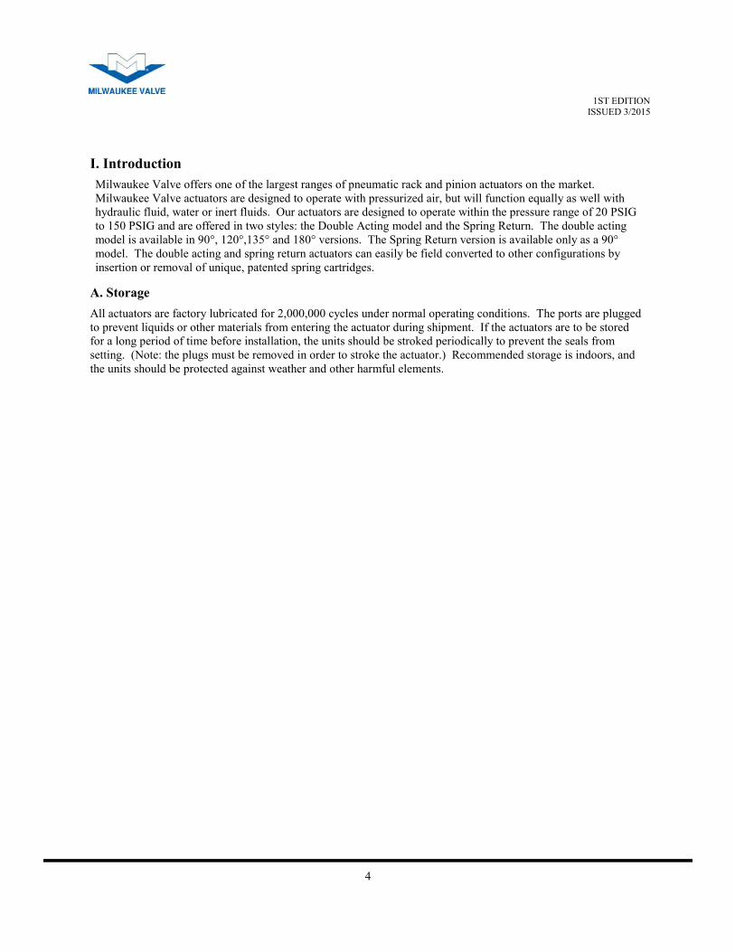
Milwaukee Valve offers one of the largest ranges of pneumatic rack and pinion actuators on the market.
Milwaukee Valve actuators are designed to operate with pressurized air, but will function equally as well with
hydraulic fluid, water or inert fluids. Our actuators are designed to operate within the pressure range of 20 PSIG
to 150 PSIG and are offered in two styles: the Double Acting model and the Spring Return. The double acting
model is available in 90°, 120°,135° and 180° versions. The Spring Return version is available only as a 90°
model. The double acting and spring return actuators can easily be field converted to other configurations by
insertion or removal of unique, patented spring cartridges.
A. Storage
All actuators are factory lubricated for 2,000,000 cycles under normal operating conditions. The ports are plugged
to prevent liquids or other materials from entering the actuator during shipment. If the actuators are to be stored
for a long period of time before installation, the units should be stroked periodically to prevent the seals from
setting. (Note: the plugs must be removed in order to stroke the actuator.) Recommended storage is indoors, and
the units should be protected against weather and other harmful elements.
I. Introduction
5
1ST EDITION ISSUED 3/2015
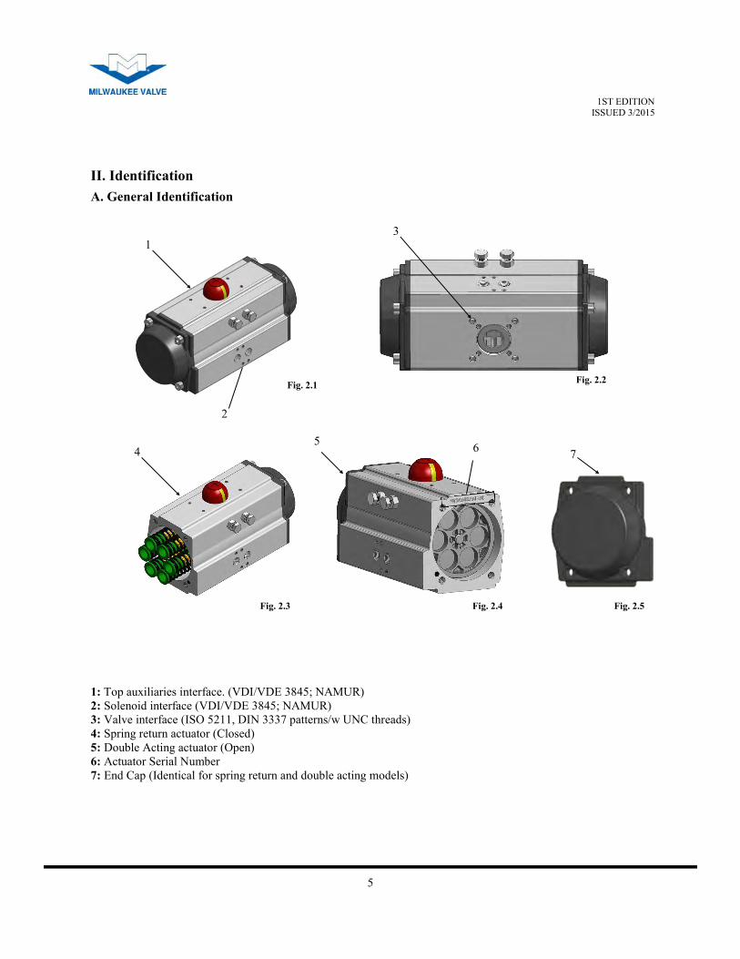
II. Identification
1: Top auxiliaries interface. (VDI/VDE 3845; NAMUR)
2: Solenoid interface (VDI/VDE 3845; NAMUR)
3: Valve interface (ISO 5211, DIN 3337 patterns/w UNC threads)
4: Spring return actuator (Closed)
5: Double Acting actuator (Open)
6: Actuator Serial Number
7: End Cap (Identical for spring return and double acting models)
1
2
5 4
3
6
A. General Identification
7
Fig. 2.1 Fig. 2.2
Fig. 2.4 Fig. 2.3 Fig. 2.5
6
1ST EDITION ISSUED 3/2015
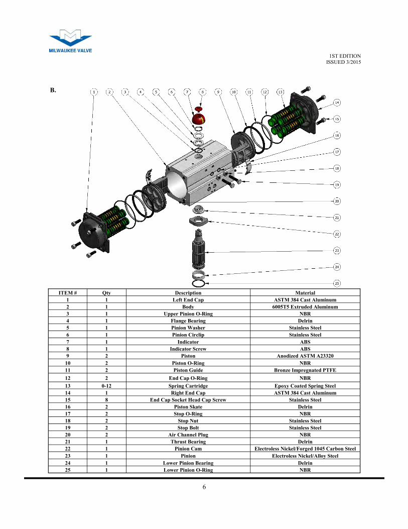
ITEM # Qty Description Material
1 1 Left End Cap ASTM 384 Cast Aluminum
2 1 Body 6005T5 Extruded Aluminum
3 1 Upper Pinion O-Ring NBR
4 1 Flange Bearing Delrin
5 1 Pinion Washer Stainless Steel
6 1 Pinion Circlip Stainless Steel
7 1 Indicator ABS
8 1 Indicator Screw ABS
9 2 Piston Anodized ASTM A23320
10 2 Piston O-Ring NBR
11 2 Piston Guide Bronze Impregnated PTFE
12 2 End Cap O-Ring NBR
13 0-12 Spring Cartridge Epoxy Coated Spring Steel
14 1 Right End Cap ASTM 384 Cast Aluminum
15 8 End Cap Socket Head Cap Screw Stainless Steel
16 2 Piston Skate Delrin
17 2 Stop O-Ring NBR
18 2 Stop Nut Stainless Steel
19 2 Stop Bolt Stainless Steel
20 2 Air Channel Plug NBR
21 1 Thrust Bearing Delrin
22 1 Pinion Cam Electroless Nickel/Forged 1045 Carbon Steel
23 1 Pinion Electroless Nickel/Alloy Steel
24 1 Lower Pinion Bearing Delrin
25 1 Lower Pinion O-Ring NBR
B.
7
1ST EDITION ISSUED 3/2015
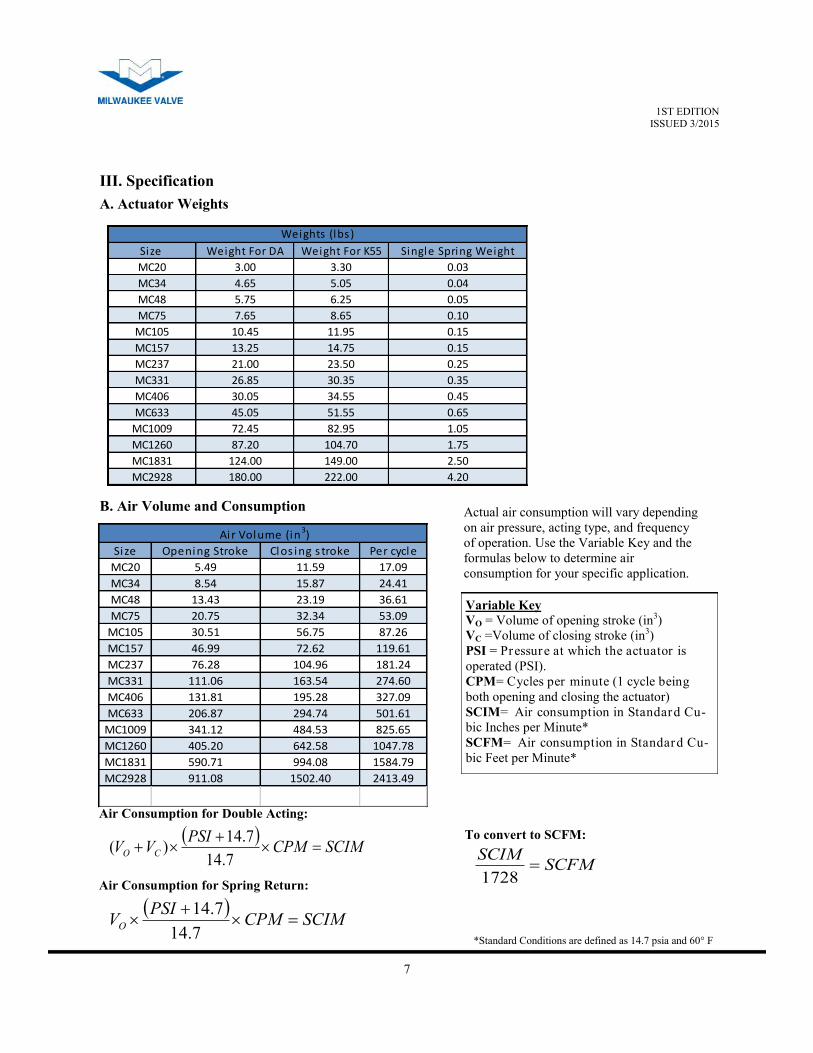
A. Actuator Weights
B. Air Volume and Consumption
Size Weight For DA Weight For K55 Single Spring Weight
MC20 3.00 3.30 0.03
MC34 4.65 5.05 0.04
MC48 5.75 6.25 0.05
MC75 7.65 8.65 0.10
MC105 10.45 11.95 0.15
MC157 13.25 14.75 0.15
MC237 21.00 23.50 0.25
MC331 26.85 30.35 0.35
MC406 30.05 34.55 0.45
MC633 45.05 51.55 0.65
MC1009 72.45 82.95 1.05
MC1260 87.20 104.70 1.75
MC1831 124.00 149.00 2.50
MC2928 180.00 222.00 4.20
Weights (lbs )
Size Opening Stroke Clos ing s troke Per cycle
MC20 5.49 11.59 17.09
MC34 8.54 15.87 24.41
MC48 13.43 23.19 36.61
MC75 20.75 32.34 53.09
MC105 30.51 56.75 87.26
MC157 46.99 72.62 119.61
MC237 76.28 104.96 181.24
MC331 111.06 163.54 274.60
MC406 131.81 195.28 327.09
MC633 206.87 294.74 501.61
MC1009 341.12 484.53 825.65
MC1260 405.20 642.58 1047.78
MC1831 590.71 994.08 1584.79
MC2928 911.08 1502.40 2413.49
Air Volume (in3)
Actual air consumption will vary depending
on air pressure, acting type, and frequency
of operation. Use the Variable Key and the
formulas below to determine air
consumption for your specific application.
Variable Key
VO = Volume of opening stroke (in3)
VC =Volume of closing stroke (in3)
PSI = Pressure at which the actuator is
operated (PSI).
CPM= Cycles per minute (1 cycle being
both opening and closing the actuator)
SCIM= Air consumption in Standard Cu-
bic Inches per Minute*
SCFM= Air consumption in Standard Cu-
bic Feet per Minute*
SCIMCPM
PSIVV CO
7.14
7.14)(
SCIMCPM
PSIVO
7.14
7.14
Air Consumption for Double Acting:
Air Consumption for Spring Return:
SCFMSCIM
1728
To convert to SCFM:
*Standard Conditions are defined as 14.7 psia and 60° F
III. Specification
8
1ST EDITION ISSUED 3/2015
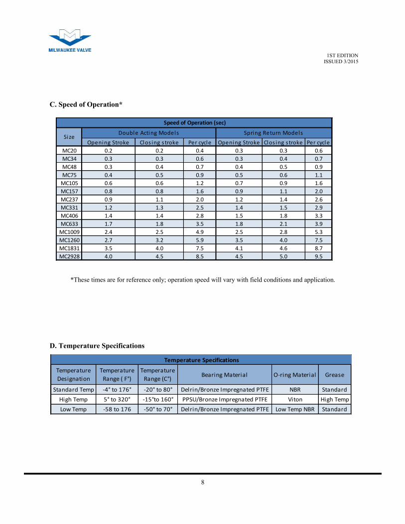
*These times are for reference only; operation speed will vary with field conditions and application.
Temperature
Designation
Temperature
Range ( F°)
Temperature
Range (C°)Bearing Material O-ring Material Grease
Standard Temp -4° to 176° -20° to 80° Delrin/Bronze Impregnated PTFE NBR Standard
High Temp 5° to 320° -15°to 160° PPSU/Bronze Impregnated PTFE Viton High Temp
Low Temp -58 to 176 -50° to 70° Delrin/Bronze Impregnated PTFE Low Temp NBR Standard
Temperature Specifications
Opening Stroke Clos ing s troke Per cycle Opening Stroke Clos ing s troke Per cycle
MC20 0.2 0.2 0.4 0.3 0.3 0.6
MC34 0.3 0.3 0.6 0.3 0.4 0.7
MC48 0.3 0.4 0.7 0.4 0.5 0.9
MC75 0.4 0.5 0.9 0.5 0.6 1.1
MC105 0.6 0.6 1.2 0.7 0.9 1.6
MC157 0.8 0.8 1.6 0.9 1.1 2.0
MC237 0.9 1.1 2.0 1.2 1.4 2.6
MC331 1.2 1.3 2.5 1.4 1.5 2.9
MC406 1.4 1.4 2.8 1.5 1.8 3.3
MC633 1.7 1.8 3.5 1.8 2.1 3.9
MC1009 2.4 2.5 4.9 2.5 2.8 5.3
MC1260 2.7 3.2 5.9 3.5 4.0 7.5
MC1831 3.5 4.0 7.5 4.1 4.6 8.7
MC2928 4.0 4.5 8.5 4.5 5.0 9.5
Double Acting ModelsSize
Spring Return Models
Speed of Operation (sec)
C. Speed of Operation*
D. Temperature Specifications
9
1ST EDITION ISSUED 3/2015
A Port B Port A Port B Port
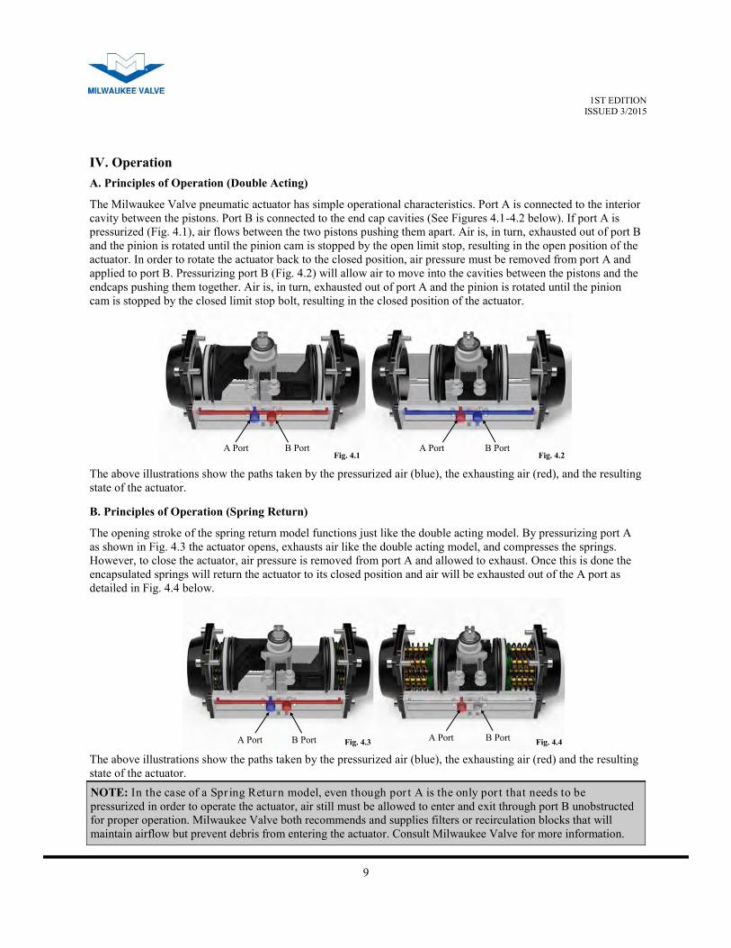
A. Principles of Operation (Double Acting)
The Milwaukee Valve pneumatic actuator has simple operational characteristics. Port A is connected to the interior
cavity between the pistons. Port B is connected to the end cap cavities (See Figures 4.1-4.2 below). If port A is
pressurized (Fig. 4.1), air flows between the two pistons pushing them apart. Air is, in turn, exhausted out of port B
and the pinion is rotated until the pinion cam is stopped by the open limit stop, resulting in the open position of the
actuator. In order to rotate the actuator back to the closed position, air pressure must be removed from port A and
applied to port B. Pressurizing port B (Fig. 4.2) will allow air to move into the cavities between the pistons and the
endcaps pushing them together. Air is, in turn, exhausted out of port A and the pinion is rotated until the pinion
cam is stopped by the closed limit stop bolt, resulting in the closed position of the actuator.
A Port B Port A Port B Port
The above illustrations show the paths taken by the pressurized air (blue), the exhausting air (red), and the resulting
state of the actuator.
Fig. 4.2 Fig. 4.1
IV. Operation
B. Principles of Operation (Spring Return)
The opening stroke of the spring return model functions just like the double acting model. By pressurizing port A
as shown in Fig. 4.3 the actuator opens, exhausts air like the double acting model, and compresses the springs.
However, to close the actuator, air pressure is removed from port A and allowed to exhaust. Once this is done the
encapsulated springs will return the actuator to its closed position and air will be exhausted out of the A port as
detailed in Fig. 4.4 below.
The above illustrations show the paths taken by the pressurized air (blue), the exhausting air (red) and the resulting
state of the actuator.
Fig. 4.4 Fig. 4.3
NOTE: In the case of a Spr ing Return model, even though por t A is the only por t that needs to be
pressurized in order to operate the actuator, air still must be allowed to enter and exit through port B unobstructed
for proper operation. Milwaukee Valve both recommends and supplies filters or recirculation blocks that will
maintain airflow but prevent debris from entering the actuator. Consult Milwaukee Valve for more information.

10
1ST EDITION ISSUED 3/2015
C. Fail Positions
NOTE: All statements above assume the valve is a quar ter turn valve that opens counterclockwise and
closes clockwise. Further, it also assumes that the actuator is spring return, since a double acting actuator will
always fail in its last position (discounting any forces the valve may exert on the actuator).
The actuator standard operation is counterclockwise to open and clockwise to close. This is referred to as a “fail
clockwise” configuration or FCW. However, it is also available in an FCCW or “fail counterclockwise”
configuration. Figures 4.5 & 4.6 show the same actuator with the piston and pinion orientation changed to convert
the actuator from the FCW to the FCCW configuration. FCW is referred to as “fail closed” and FCCW as “fail
open” due to its intended effect on the valve. In the diagrams below, the hollow arrows show the direction the
pistons move due to the spring force, and the solid arrows show rotation of the pinion as it travels to the fail
position.
Fig. 4.5 shows a FCW, spring return actuator going from the open position (left) to the fail, or closed, position
(right).
Fig. 4.6 shows a FCCW, spring return actuator going from the open position (left) to the fail, or closed, position
(right).
FCW (Fail Closed) Fig.4.5
FCCW (Fail Opened) Fig.4.6
11
1ST EDITION ISSUED 3/2015
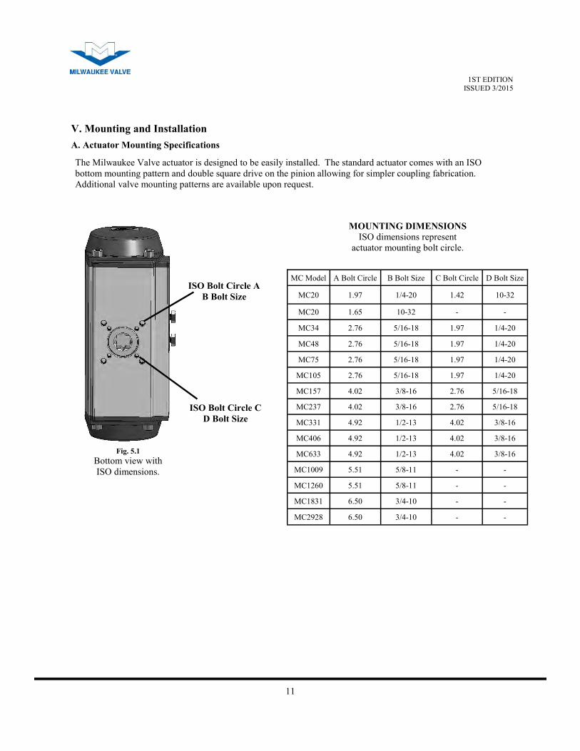
The Milwaukee Valve actuator is designed to be easily installed. The standard actuator comes with an ISO
bottom mounting pattern and double square drive on the pinion allowing for simpler coupling fabrication.
Additional valve mounting patterns are available upon request.
ISO Bolt Circle A
B Bolt Size
ISO Bolt Circle C
D Bolt Size
Fig. 5.1
Bottom view with
ISO dimensions.
MOUNTING DIMENSIONS
ISO dimensions represent
actuator mounting bolt circle.
MC Model A Bolt Circle B Bolt Size C Bolt Circle D Bolt Size
MC20 1.97 1/4-20 1.42 10-32
MC20 1.65 10-32 - -
MC34 2.76 5/16-18 1.97 1/4-20
MC48 2.76 5/16-18 1.97 1/4-20
MC75 2.76 5/16-18 1.97 1/4-20
MC105 2.76 5/16-18 1.97 1/4-20
MC157 4.02 3/8-16 2.76 5/16-18
MC237 4.02 3/8-16 2.76 5/16-18
MC331 4.92 1/2-13 4.02 3/8-16
MC406 4.92 1/2-13 4.02 3/8-16
MC633 4.92 1/2-13 4.02 3/8-16
MC1009 5.51 5/8-11 - -
MC1260 5.51 5/8-11 - -
MC1831 6.50 3/4-10 - -
MC2928 6.50 3/4-10 - -
V. Mounting and Installation
A. Actuator Mounting Specifications
12
1ST EDITION ISSUED 3/2015
WARNING!
Never attempt to assemble, disassemble, or otherwise modify an actuator while still in service!
Disconnect both pneumatic and electrical power from the actuator and ensure it’s completely
exhausted before making any adjustments!
Note: The Milwaukee Valve actuator is designed to be installed, commissioned, and maintained using
commonly available tools such as hex keys, crescent wrenches, circlip pliers, and socket wrenches.
During assembly to the valve, do not use a hammer on the pinion top. This can damage the pinion and thrust
bearing causing premature failure.
Before mounting the actuator on the valve or valve bracket, be sure to understand the valve and actuator’s failure
position and rotation characteristics.
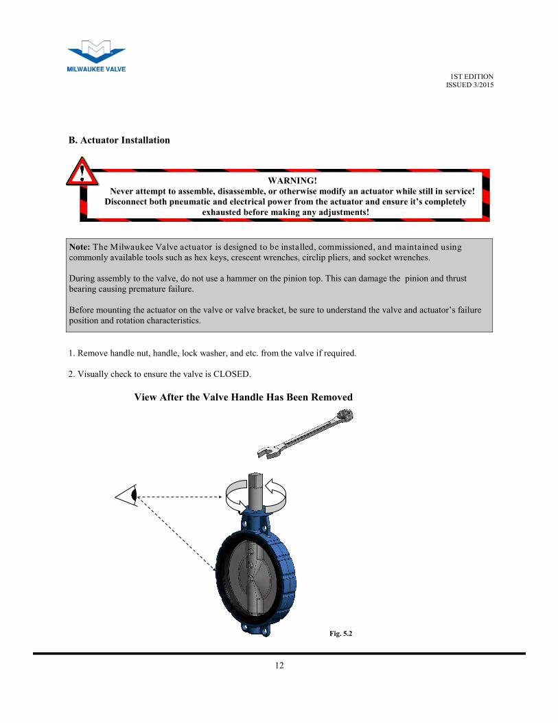
1. Remove handle nut, handle, lock washer, and etc. from the valve if required.
2. Visually check to ensure the valve is CLOSED.
View After the Valve Handle Has Been Removed
B. Actuator Installation
Fig. 5.2
13
1ST EDITION ISSUED 3/2015
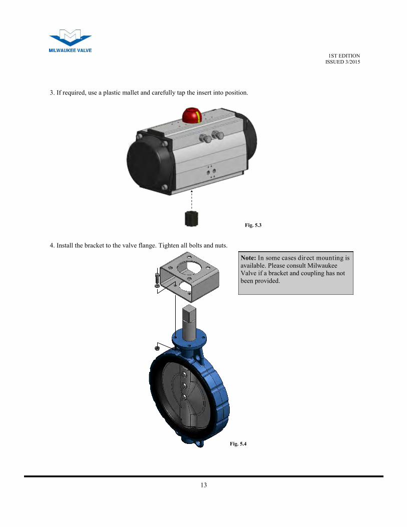
3. If required, use a plastic mallet and carefully tap the insert into position.
4. Install the bracket to the valve flange. Tighten all bolts and nuts.
Note: In some cases direct mounting is
available. Please consult Milwaukee
Valve if a bracket and coupling has not
been provided.
Fig. 5.3
Fig. 5.4
14
1ST EDITION ISSUED 3/2015
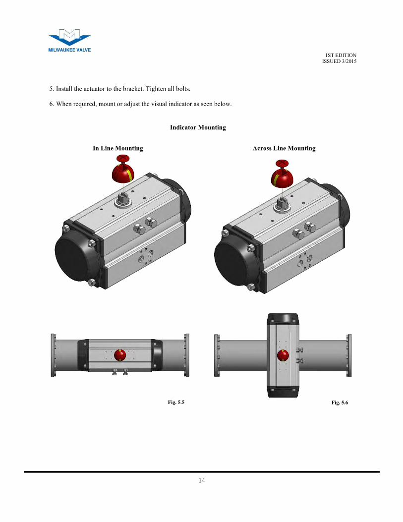
Indicator Mounting
In Line Mounting Across Line Mounting
5. Install the actuator to the bracket. Tighten all bolts.
6. When required, mount or adjust the visual indicator as seen below.
Fig. 5.5 Fig. 5.6
15
1ST EDITION ISSUED 3/2015
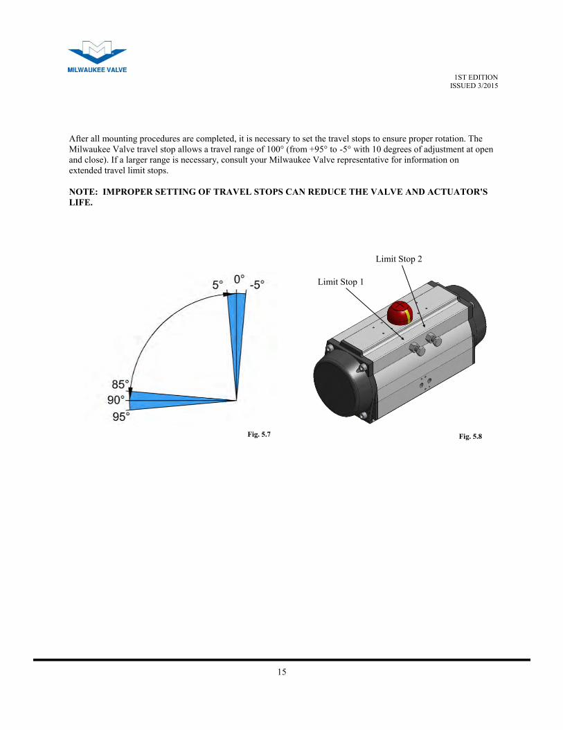
After all mounting procedures are completed, it is necessary to set the travel stops to ensure proper rotation. The
Milwaukee Valve travel stop allows a travel range of 100° (from +95° to -5° with 10 degrees of adjustment at open
and close). If a larger range is necessary, consult your Milwaukee Valve representative for information on
extended travel limit stops.
NOTE: IMPROPER SETTING OF TRAVEL STOPS CAN REDUCE THE VALVE AND ACTUATOR'S
LIFE.
Limit Stop 1
Limit Stop 2
Fig. 5.7 Fig. 5.8
16
1ST EDITION ISSUED 3/2015
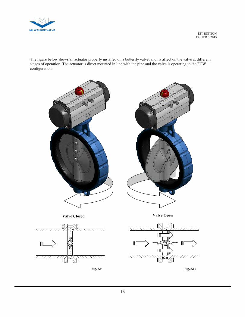
The figure below shows an actuator properly installed on a butterfly valve, and its affect on the valve at different
stages of operation. The actuator is direct mounted in line with the pipe and the valve is operating in the FCW
configuration.
Valve Closed Valve Open
Fig. 5.9 Fig. 5.10

17
1ST EDITION ISSUED 3/2015
Milwaukee Valve actuators have open and close travel stops for +5°/-5° of travel.
1. Operate the actuator assembly to the closed position.
2. Remove/lockout the air supply to the actuator.
3. Loosen the locknut on the closed stop.
4. Turn the closed stop clockwise to reduce or counterclockwise to increase the travel.
5. Retighten the locknut.
6. Reconnect the air supply to check that the position desired is correct. If not repeat.
7. Operate the actuator assembly to the open position.
8. Remove/lockout the air supply to the actuator.
9. Loosen the locknut on the open stop.
10. Turn the top clockwise to reduce or counterclockwise to increase the travel.
11. Retighten the locknut.
12. Reconnect the air supply to check that the position desired is correct. If not repeat items 7-11.
Open Limit Stop Closed Limit Stop
VI. Travel Stop Adjustment
A. Setting The Stops on Double Acting Units
The above illustration shows a double acting actuator in the open position and identifies the opening and closing
limit stops.
Fig. 6.1
18
1ST EDITION ISSUED 3/2015
1. Remove the air supply to the A port. Actuator will move to the closed position. Please note the position
of the actuator.
2. Apply air to open the actuator. Please note the position of the actuator in the open position.
3. While the air supply is maintained, carefully loosen the locknut on the closed stop and adjust the stop to
the correct position desired.
4. Retighten the locknut.
5. Remove the air supply and the actuator will go to the closed position desired.
6. If the correct position is not achieved repeat 1-5.
7. Loosen the locknut on the open stop and adjust the travel desired. (Clockwise adjustment decreases
travel.)
8. Retighten the locknut.
9. Apply air and check the open position. If not correct repeat instructions 5-8.
Open Limit Stop Closed Limit Stop
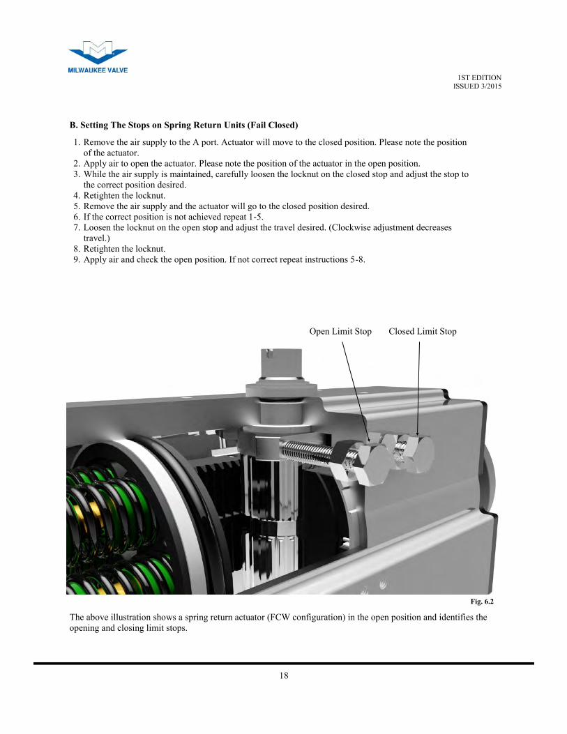
B. Setting The Stops on Spring Return Units (Fail Closed)
The above illustration shows a spring return actuator (FCW configuration) in the open position and identifies the
opening and closing limit stops.
Fig. 6.2
19
1ST EDITION ISSUED 3/2015
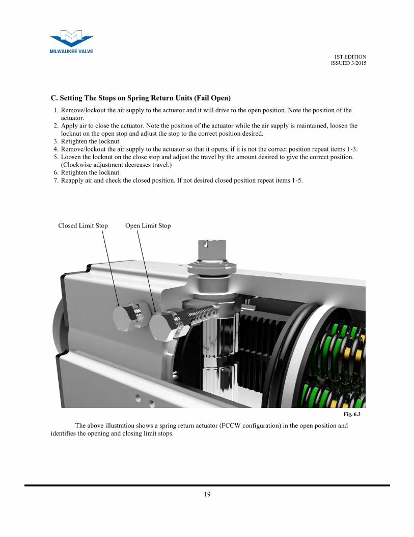
1. Remove/lockout the air supply to the actuator and it will drive to the open position. Note the position of the
actuator.
2. Apply air to close the actuator. Note the position of the actuator while the air supply is maintained, loosen the
locknut on the open stop and adjust the stop to the correct position desired.
3. Retighten the locknut.
4. Remove/lockout the air supply to the actuator so that it opens, if it is not the correct position repeat items 1-3.
5. Loosen the locknut on the close stop and adjust the travel by the amount desired to give the correct position.
(Clockwise adjustment decreases travel.)
6. Retighten the locknut.
7. Reapply air and check the closed position. If not desired closed position repeat items 1-5.
Open Limit Stop Closed Limit Stop
C. Setting The Stops on Spring Return Units (Fail Open)
The above illustration shows a spring return actuator (FCCW configuration) in the open position and
identifies the opening and closing limit stops.
Fig. 6.3
20
1ST EDITION ISSUED 3/2015
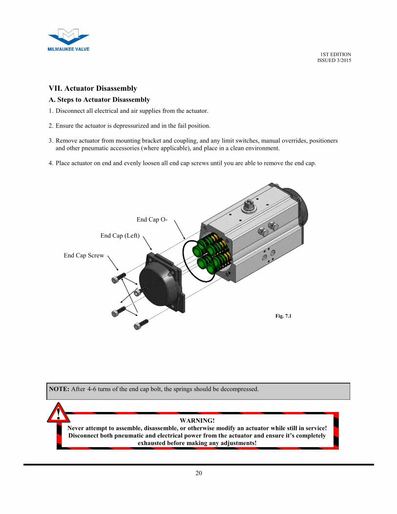
VII. Actuator Disassembly
End Cap Screw
End Cap (Left)
End Cap O-
1. Disconnect all electrical and air supplies from the actuator.
2. Ensure the actuator is depressurized and in the fail position.
3. Remove actuator from mounting bracket and coupling, and any limit switches, manual overrides, positioners
and other pneumatic accessories (where applicable), and place in a clean environment.
4. Place actuator on end and evenly loosen all end cap screws until you are able to remove the end cap.
NOTE: After 4-6 turns of the end cap bolt, the springs should be decompressed.
WARNING!
Never attempt to assemble, disassemble, or otherwise modify an actuator while still in service!
Disconnect both pneumatic and electrical power from the actuator and ensure it’s completely
exhausted before making any adjustments!
A. Steps to Actuator Disassembly
Fig. 7.1

21
1ST EDITION ISSUED 3/2015
Spring Cartridges
5. Remove any springs and repeat for the other side.
Stop Nuts
Stop Bolts
Stop O-Rings
6. Loosen both limit stop nuts then remove both limit stop bolts to allow full rotation of the pinion.
Fig. 7.2
Fig. 7.3
22
1ST EDITION ISSUED 3/2015
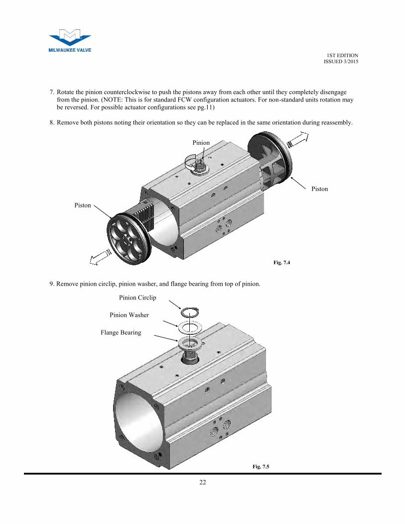
Pinion
Piston
Piston
7. Rotate the pinion counterclockwise to push the pistons away from each other until they completely disengage
from the pinion. (NOTE: This is for standard FCW configuration actuators. For non-standard units rotation may
be reversed. For possible actuator configurations see pg.11)
8. Remove both pistons noting their orientation so they can be replaced in the same orientation during reassembly.
Pinion Circlip
Pinion Washer
Flange Bearing
9. Remove pinion circlip, pinion washer, and flange bearing from top of pinion.
Fig. 7.4
Fig. 7.5
23
1ST EDITION ISSUED 3/2015
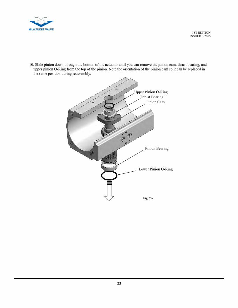
Upper Pinion O-Ring
Pinion Cam
Thrust Bearing
Pinion Bearing
Lower Pinion O-Ring
10. Slide pinion down through the bottom of the actuator until you can remove the pinion cam, thrust bearing, and
upper pinion O-Ring from the top of the pinion. Note the orientation of the pinion cam so it can be replaced in
the same position during reassembly.
Fig. 7.6
24
1ST EDITION ISSUED 3/2015
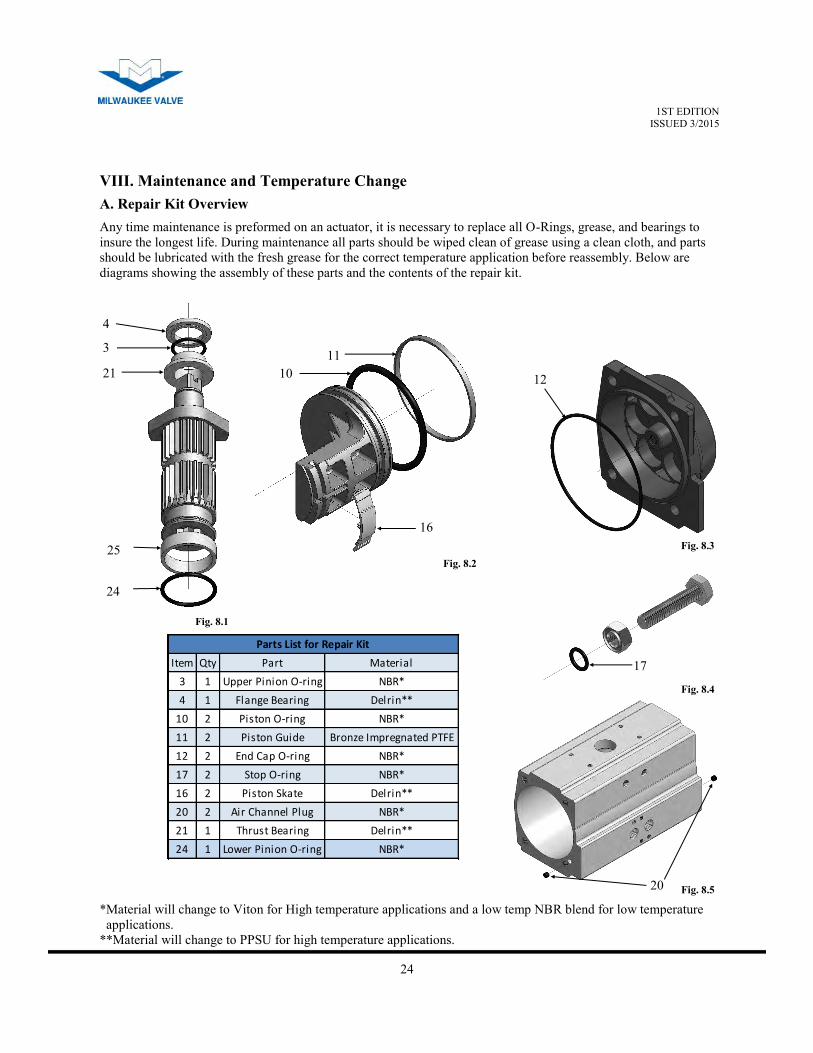
VIII. Maintenance and Temperature Change
Any time maintenance is preformed on an actuator, it is necessary to replace all O-Rings, grease, and bearings to
insure the longest life. During maintenance all parts should be wiped clean of grease using a clean cloth, and parts
should be lubricated with the fresh grease for the correct temperature application before reassembly. Below are
diagrams showing the assembly of these parts and the contents of the repair kit.
Item Qty Part Material
3 1 Upper Pinion O-ring NBR*
4 1 Flange Bearing Delrin**
10 2 Piston O-ring NBR*
11 2 Piston Guide Bronze Impregnated PTFE
12 2 End Cap O-ring NBR*
17 2 Stop O-ring NBR*
16 2 Piston Skate Delrin**
20 2 Air Channel Plug NBR*
21 1 Thrust Bearing Delrin**
24 1 Lower Pinion O-ring NBR*
Parts List for Repair Kit
*Material will change to Viton for High temperature applications and a low temp NBR blend for low temperature
*applications.
**Material will change to PPSU for high temperature applications.
A. Repair Kit Overview
20 Fig. 8.5
17
Fig. 8.4
16
10
11
Fig. 8.2
12
Fig. 8.3
3
21
25
24
4
Fig. 8.1

25
1ST EDITION ISSUED 3/2015
1. Disassemble actuator as described in on pg. 21-24.
2. Remove the O-Rings and bearings from the various actuator components:
(See fig. 8.1-8.5 on the previous page for list of parts to be replaced and their locations)
a. Piston O-Rings (2)
b. End Caps (2)
c. Upper Pinion O-Ring (1)
d. Lower Pinion O-Ring (1)
e. Air Passage Plugs (2)
f. Stop O-Rings (2)
g. Pinion Bearing (1)
h. Thrust Bearing (1)
i. Flange Washer (1)
3. Using mineral spirits (or other mild solvent), remove the lubrication from each actuator component. (Note:
clean all surfaces thoroughly prior to installation of new O-Ring set.)
4. Separate O-Rings and determine the locations for installation:
a. Piston O-Rings: will be the thickest O-Rings (2 pieces), (#10 fig. 8.2)
b. End Cap O-Rings: will have the largest O-Ring diameter (2 pieces), (#12 fig. 8.3)
c. Pinion O-Rings: of the remaining O-Rings, the largest is installed in the lower pinion
O-Ring groove (#24 fig. 8.1). The second largest is installed on the top of the pinion (#3 fig. 8.1).
d. Air Channel Plugs: the small cylinders fit in the ends of the body (2 pieces), (#20 fig. 8.5).
e. Stop O-Rings: will have the smallest O-Ring diameter (#17 fig. 8.4).
(Note: if these O-Rings are not properly seated, they may be pinched during reassembly and
subsequently leak.)
5. Identify bearing parts and their installation locations:
a. Piston Skates (#16 fig. 8.2)
b. Thrust Bearing (#5 fig. 8.1)
c. Flange Bearing (#4 fig. 8.4)
6. Apply light grease to the internal portions of the actuator for ease of reassembly:
a. Inner bore of actuator.
b. Piston wear surfaces (piston skate, piston bearing & piston O-Ring).
c. Piston rack (apply on the full length of the piston rack).
d. Pinion gear teeth.
e. Pinion wear surfaces and O-Rings (both upper and lower areas).
7. Assemble actuator as described on pg. 27-31. If the O-Rings are difficult to install, the O-Rings may be
slightly stretched and lubricated to ease installation. (Note: be sure to use the lubricant provided when
lubricating the O-Rings.) When installing the end cap O-Rings, be sure to seat the O-Ring properly, a thin
layer of grease will help hold the O-Ring in place.
B. Installing Repair Kit or Changing Temperature Rating
Follow the listed steps to install a repair kit or change temperature applications. For reference the various
temperature specifications and materials can be found on pg. 9 of this manual.
26
1ST EDITION ISSUED 3/2015
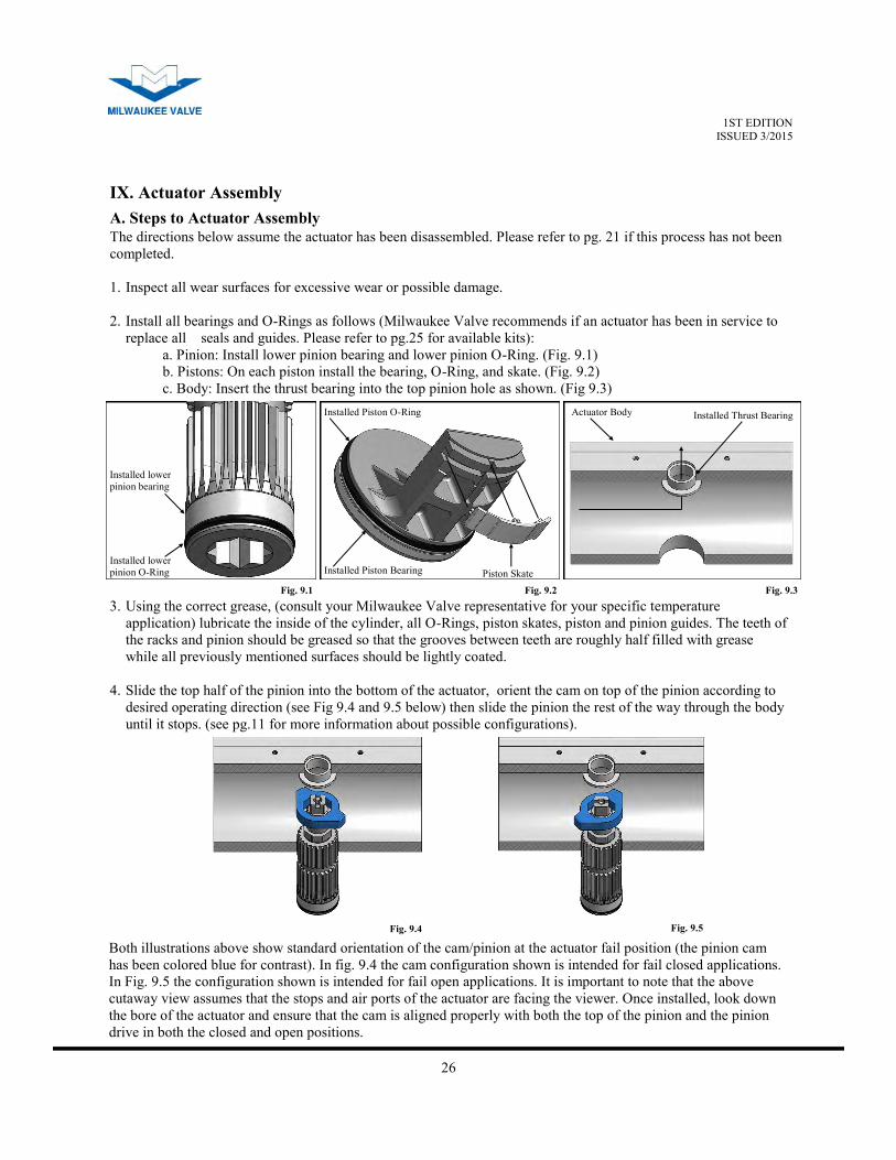
IX. Actuator Assembly
Installed lower
pinion O-Ring
Installed lower
pinion bearing
Fig. 9.1
Piston Skate Installed Piston Bearing
Installed Piston O-Ring
Fig. 9.2
Actuator Body Installed Thrust Bearing
Fig. 9.3
3. Using the correct grease, (consult your Milwaukee Valve representative for your specific temperature
application) lubricate the inside of the cylinder, all O-Rings, piston skates, piston and pinion guides. The teeth of
the racks and pinion should be greased so that the grooves between teeth are roughly half filled with grease
while all previously mentioned surfaces should be lightly coated.
4. Slide the top half of the pinion into the bottom of the actuator, orient the cam on top of the pinion according to
desired operating direction (see Fig 9.4 and 9.5 below) then slide the pinion the rest of the way through the body
until it stops. (see pg.11 for more information about possible configurations).
Both illustrations above show standard orientation of the cam/pinion at the actuator fail position (the pinion cam
has been colored blue for contrast). In fig. 9.4 the cam configuration shown is intended for fail closed applications.
In Fig. 9.5 the configuration shown is intended for fail open applications. It is important to note that the above
cutaway view assumes that the stops and air ports of the actuator are facing the viewer. Once installed, look down
the bore of the actuator and ensure that the cam is aligned properly with both the top of the pinion and the pinion
drive in both the closed and open positions.
Fig. 9.4 Fig. 9.5
A. Steps to Actuator Assembly
The directions below assume the actuator has been disassembled. Please refer to pg. 21 if this process has not been
completed.
1. Inspect all wear surfaces for excessive wear or possible damage.
2. Install all bearings and O-Rings as follows (Milwaukee Valve recommends if an actuator has been in service to
replace all seals and guides. Please refer to pg.25 for available kits):
a. Pinion: Install lower pinion bearing and lower pinion O-Ring. (Fig. 9.1)
b. Pistons: On each piston install the bearing, O-Ring, and skate. (Fig. 9.2)
c. Body: Insert the thrust bearing into the top pinion hole as shown. (Fig 9.3)
27
1ST EDITION ISSUED 3/2015
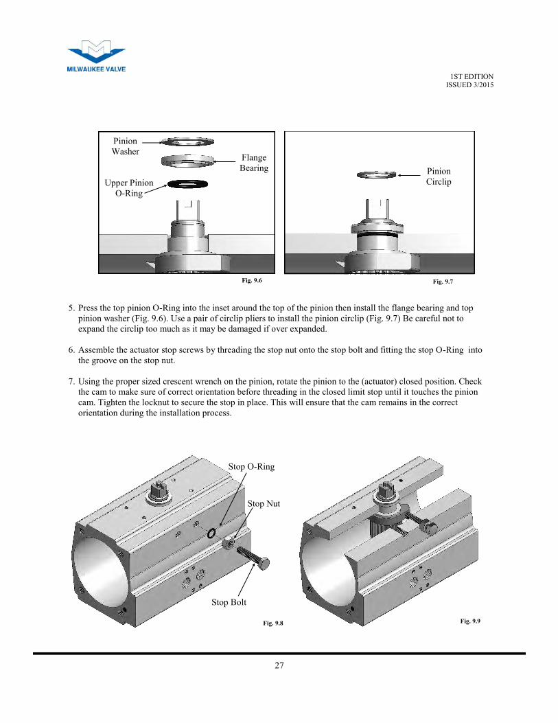
5. Press the top pinion O-Ring into the inset around the top of the pinion then install the flange bearing and top
pinion washer (Fig. 9.6). Use a pair of circlip pliers to install the pinion circlip (Fig. 9.7) Be careful not to
expand the circlip too much as it may be damaged if over expanded.
6. Assemble the actuator stop screws by threading the stop nut onto the stop bolt and fitting the stop O-Ring into
the groove on the stop nut.
7. Using the proper sized crescent wrench on the pinion, rotate the pinion to the (actuator) closed position. Check
the cam to make sure of correct orientation before threading in the closed limit stop until it touches the pinion
cam. Tighten the locknut to secure the stop in place. This will ensure that the cam remains in the correct
orientation during the installation process.
Fig. 9.6 Fig. 9.7
Fig. 9.8 Fig. 9.9
Pinion
Washer
Upper Pinion
O-Ring
Flange
Bearing Pinion
Circlip
Stop O-Ring
Stop Nut
Stop Bolt
28
1ST EDITION ISSUED 3/2015
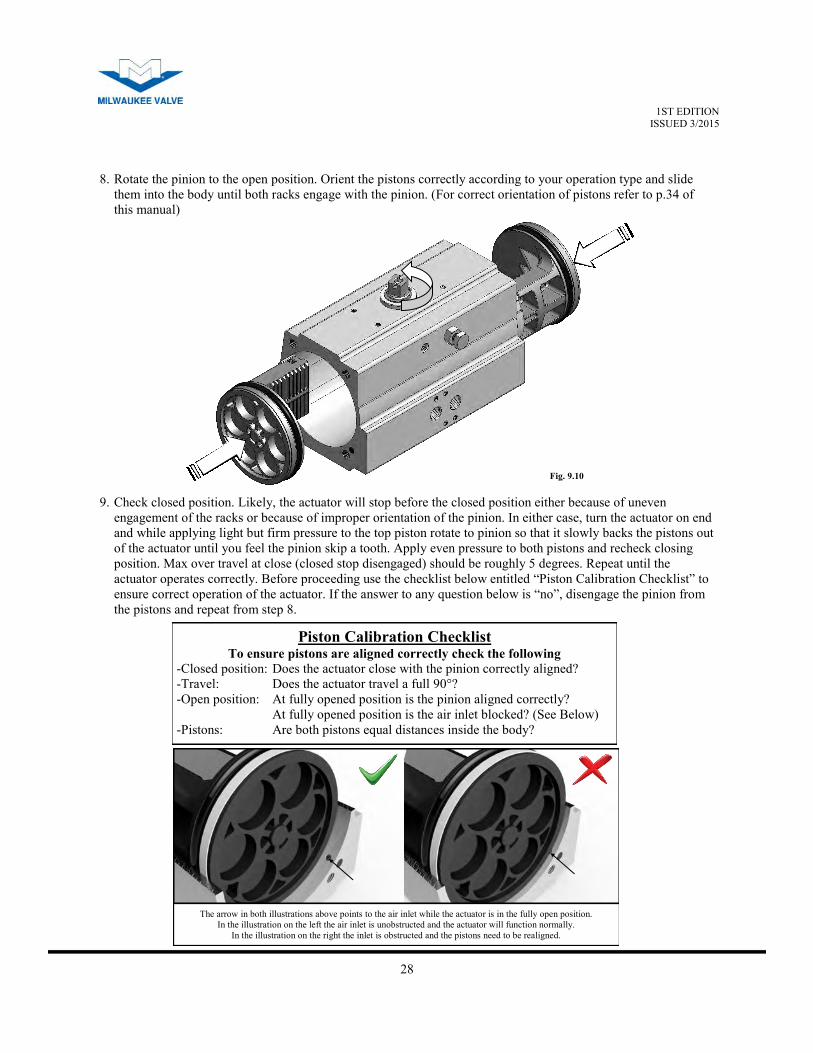
9. Check closed position. Likely, the actuator will stop before the closed position either because of uneven
engagement of the racks or because of improper orientation of the pinion. In either case, turn the actuator on end
and while applying light but firm pressure to the top piston rotate to pinion so that it slowly backs the pistons out
of the actuator until you feel the pinion skip a tooth. Apply even pressure to both pistons and recheck closing
position. Max over travel at close (closed stop disengaged) should be roughly 5 degrees. Repeat until the
actuator operates correctly. Before proceeding use the checklist below entitled “Piston Calibration Checklist” to
ensure correct operation of the actuator. If the answer to any question below is “no”, disengage the pinion from
the pistons and repeat from step 8.
Piston Calibration Checklist To ensure pistons are aligned correctly check the following
-Closed position: Does the actuator close with the pinion correctly aligned?
-Travel: Does the actuator travel a full 90°?
-Open position: At fully opened position is the pinion aligned correctly?
At fully opened position is the air inlet blocked? (See Below)
-Pistons: Are both pistons equal distances inside the body?
The arrow in both illustrations above points to the air inlet while the actuator is in the fully open position.
In the illustration on the left the air inlet is unobstructed and the actuator will function normally.
In the illustration on the right the inlet is obstructed and the pistons need to be realigned.
Fig. 9.10
8. Rotate the pinion to the open position. Orient the pistons correctly according to your operation type and slide
them into the body until both racks engage with the pinion. (For correct orientation of pistons refer to p.34 of
this manual)
29
1ST EDITION ISSUED 3/2015
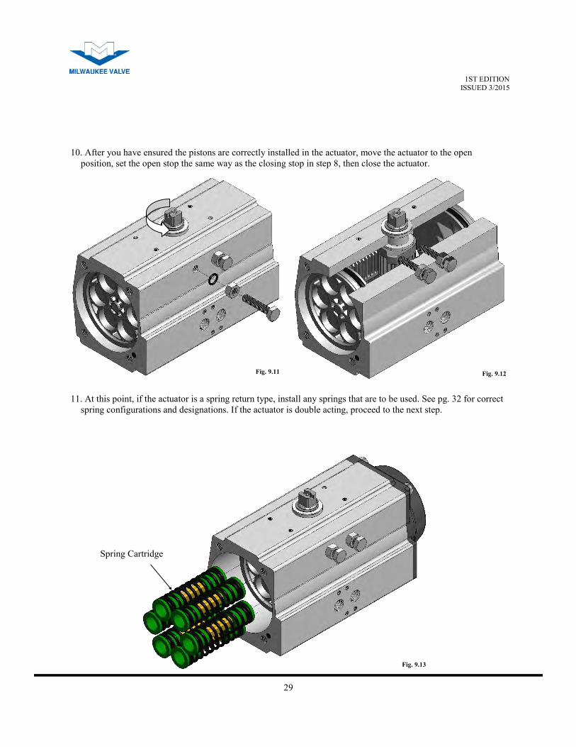
10. After you have ensured the pistons are correctly installed in the actuator, move the actuator to the open
position, set the open stop the same way as the closing stop in step 8, then close the actuator.
11. At this point, if the actuator is a spring return type, install any springs that are to be used. See pg. 32 for correct
spring configurations and designations. If the actuator is double acting, proceed to the next step.
Fig. 9.11 Fig. 9.12
Fig. 9.13
Spring Cartridge
30
1ST EDITION ISSUED 3/2015
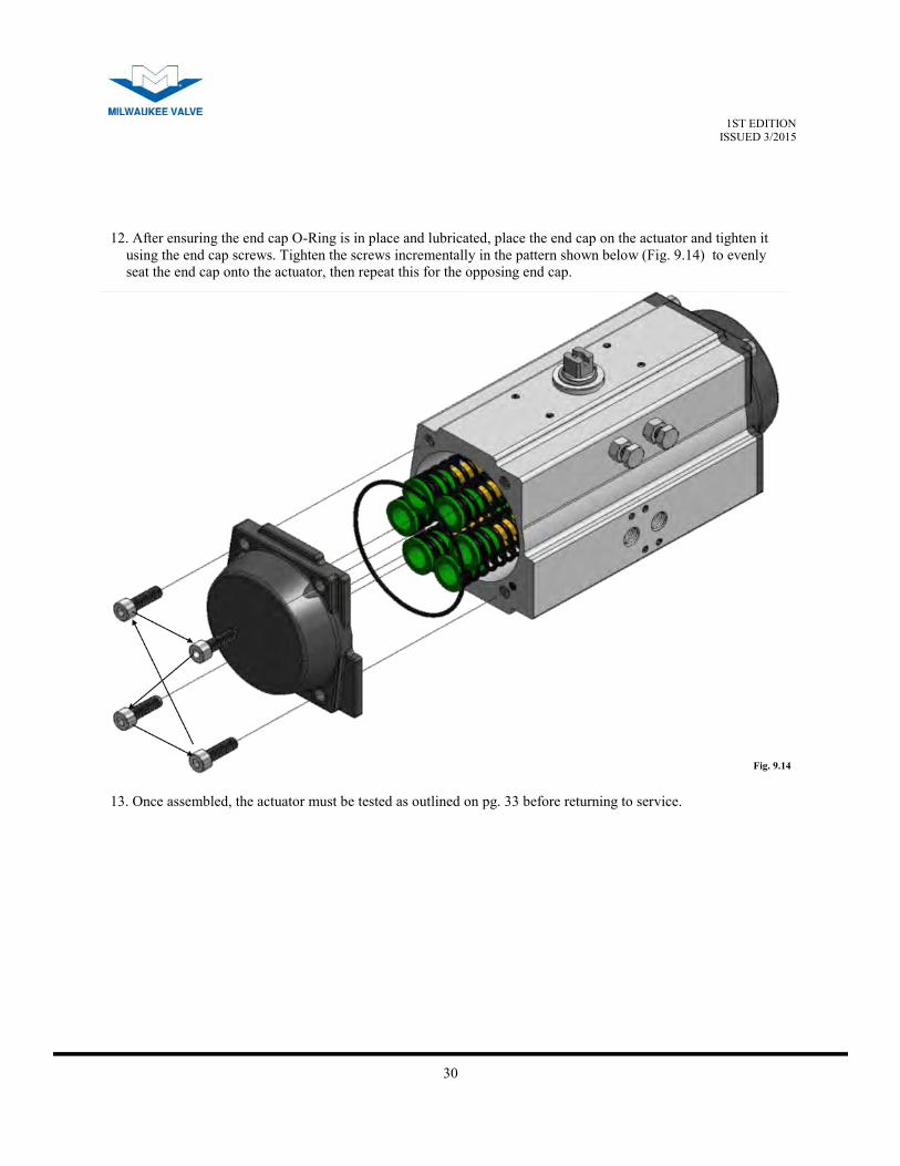
12. After ensuring the end cap O-Ring is in place and lubricated, place the end cap on the actuator and tighten it
using the end cap screws. Tighten the screws incrementally in the pattern shown below (Fig. 9.14) to evenly
seat the end cap onto the actuator, then repeat this for the opposing end cap.
Fig. 9.14
13. Once assembled, the actuator must be tested as outlined on pg. 33 before returning to service.
31
1ST EDITION ISSUED 3/2015
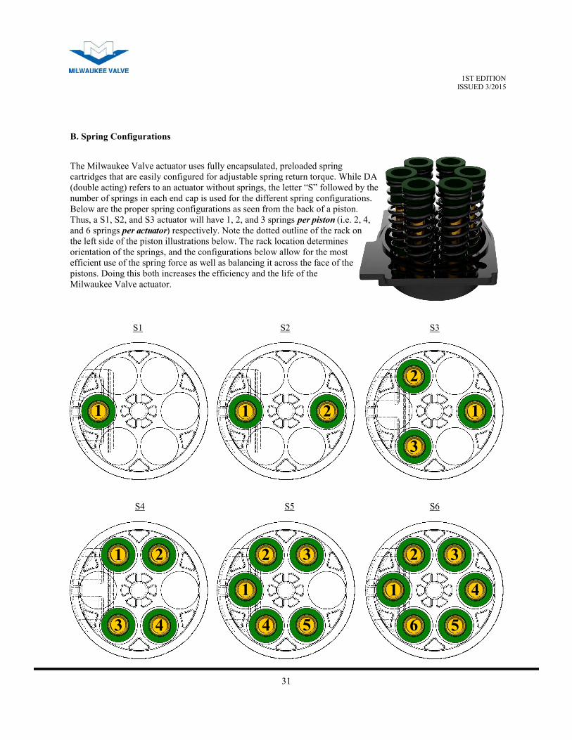
B. Spring Configurations
S1
S4 S5 S6
S3 S2
The Milwaukee Valve actuator uses fully encapsulated, preloaded spring
cartridges that are easily configured for adjustable spring return torque. While DA
(double acting) refers to an actuator without springs, the letter “S” followed by the
number of springs in each end cap is used for the different spring configurations.
Below are the proper spring configurations as seen from the back of a piston.
Thus, a S1, S2, and S3 actuator will have 1, 2, and 3 springs per piston (i.e. 2, 4,
and 6 springs per actuator) respectively. Note the dotted outline of the rack on
the left side of the piston illustrations below. The rack location determines
orientation of the springs, and the configurations below allow for the most
efficient use of the spring force as well as balancing it across the face of the
pistons. Doing this both increases the efficiency and the life of the
Milwaukee Valve actuator.
1 1 2 1
2
3
1 2
3 4
1
2 3
4 5
1
2 3
4
5 6

32
1ST EDITION ISSUED 3/2015
1 2
3 3
4
Any time the actuator is modified or undergoes maintenance, a leak test needs to be completed to insure the
actuator is air tight and working correctly.
To perform an air leak test:
1. Use a soap and water mixture to coat the actuator at the designated points below:
a. Around the base of the pinion neck (1).
b. Around the base of the stops (2).
c. Endcaps (3)
d. The pinion base (4).
C. Air Leak Test
Port A Port B
2. Apply air pressure to ports A and B (max 8bar/120psi). Any air leaks will be indicated with the soap bubbling.
3. In case of leakage around:
a. The limit stop bolts: check for O-Ring damage, if none is found, turn the lock nut tighter until it no
longer leaks.
b. The endcaps: Disassemble the endcaps and check the O-Ring for damage, if none is found ensure the
endcaps are properly seated and tightened.
c. The pinion top or bottom disassemble the actuator, replace the O-Rings and reassemble.
Fig. 9.16 Fig. 9.17
33
1ST EDITION ISSUED 3/2015
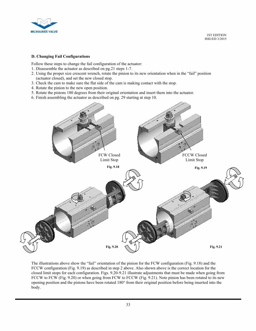
D. Changing Fail Configurations
Follow these steps to change the fail configuration of the actuator:
1. Disassemble the actuator as described on pg.21 steps 1-7.
2. Using the proper size crescent wrench, rotate the pinion to its new orientation when in the “fail” position
(actuator closed), and set the new closed stop.
3. Check the cam to make sure the flat side of the cam is making contact with the stop.
4. Rotate the pinion to the new open position.
5. Rotate the pistons 180 degrees from their original orientation and insert them into the actuator.
6. Finish assembling the actuator as described on pg. 29 starting at step 10.
Fig. 9.18 Fig. 9.19
Fig. 9.20 Fig. 9.21
The illustrations above show the “fail” orientation of the pinion for the FCW configuration (Fig. 9.18) and the
FCCW configuration (Fig. 9.19) as described in step 2 above. Also shown above is the correct location for the
closed limit stops for each configuration. Figs. 9.20-9.21 illustrate adjustments that must be made when going from
FCCW to FCW (Fig. 9.20) or when going from FCW to FCCW (Fig. 9.21). Note pinion has been rotated to its new
opening position and the pistons have been rotated 180° from their original position before being inserted into the
body.
FCW Closed
Limit Stop
FCCW Closed
Limit Stop
34
1ST EDITION ISSUED 3/2015
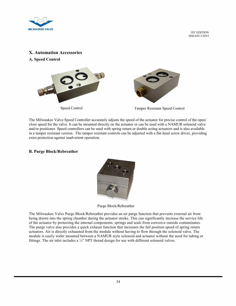
X. Automation Accessories
The Milwaukee Valve Speed Controller accurately adjusts the speed of the actuator for precise control of the open/
close speed for the valve. It can be mounted directly on the actuator or can be used with a NAMUR solenoid valve
and/or positioner. Speed controllers can be used with spring return or double acting actuators and is also available
in a tamper resistant version. The tamper resistant controls can be adjusted with a flat head screw driver, providing
extra protection against inadvertent operation.
Speed Control
Tamper Resistant Speed Control
A. Speed Control
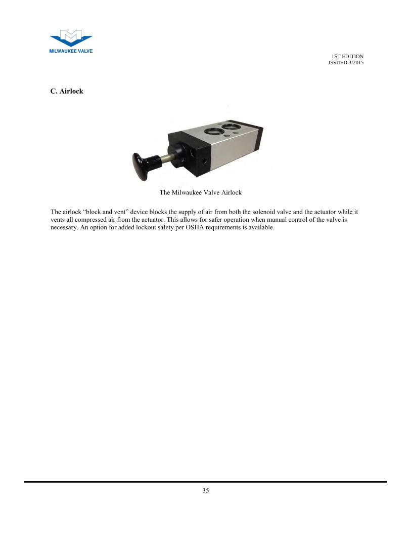
The Milwaukee Valve Purge Block/Rebreather provides an air purge function that prevents external air from
being drawn into the spring chamber during the actuator stroke. This can significantly increase the service life
of the actuator by protecting the internal components, springs and seals from corrosive outside contaminates.
The purge valve also provides a quick exhaust function that increases the fail position speed of spring return
actuators. Air is directly exhausted from the module without having to flow through the solenoid valve. The
module is easily wafer mounted between a NAMUR style solenoid and actuator without the need for tubing or
fittings. The air inlet includes a ¼” NPT thread design for use with different solenoid valves.
Purge Block/Rebreather
B. Purge Block/Rebreather
35
1ST EDITION ISSUED 3/2015
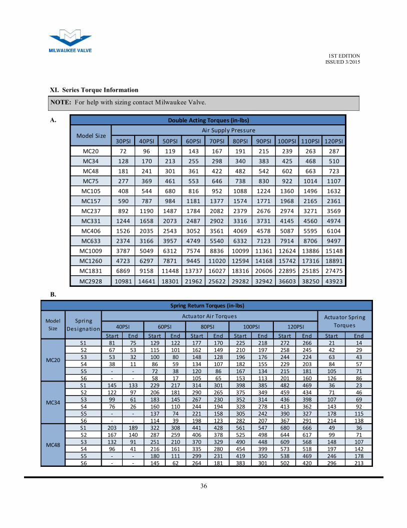
The airlock “block and vent” device blocks the supply of air from both the solenoid valve and the actuator while it
vents all compressed air from the actuator. This allows for safer operation when manual control of the valve is
necessary. An option for added lockout safety per OSHA requirements is available.
The Milwaukee Valve Airlock
C. Airlock
36
1ST EDITION ISSUED 3/2015
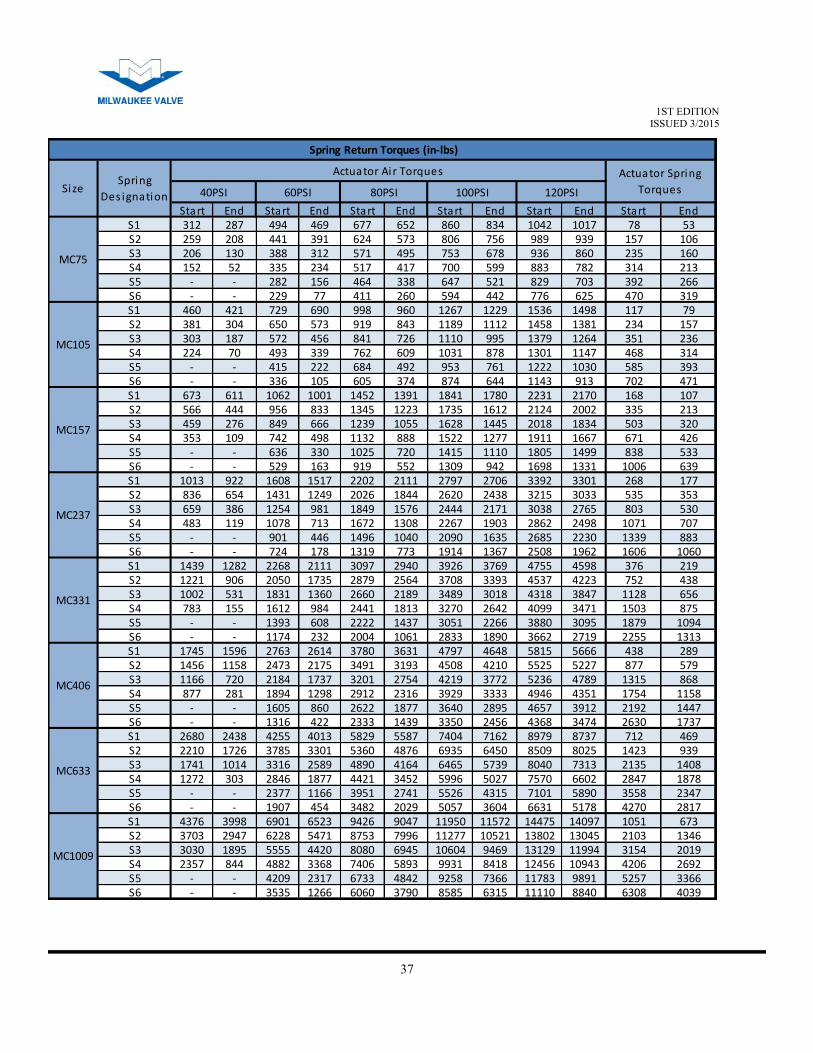
XI. Series Torque Information
30PSI 40PSI 50PSI 60PSI 70PSI 80PSI 90PSI 100PSI 110PSI 120PSI
MC20 72 96 119 143 167 191 215 239 263 287
MC34 128 170 213 255 298 340 383 425 468 510
MC48 181 241 301 361 422 482 542 602 663 723
MC75 277 369 461 553 646 738 830 922 1014 1107
MC105 408 544 680 816 952 1088 1224 1360 1496 1632
MC157 590 787 984 1181 1377 1574 1771 1968 2165 2361
MC237 892 1190 1487 1784 2082 2379 2676 2974 3271 3569
MC331 1244 1658 2073 2487 2902 3316 3731 4145 4560 4974
MC406 1526 2035 2543 3052 3561 4069 4578 5087 5595 6104
MC633 2374 3166 3957 4749 5540 6332 7123 7914 8706 9497
MC1009 3787 5049 6312 7574 8836 10099 11361 12624 13886 15148
MC1260 4723 6297 7871 9445 11020 12594 14168 15742 17316 18891
MC1831 6869 9158 11448 13737 16027 18316 20606 22895 25185 27475
MC2928 10981 14641 18301 21962 25622 29282 32942 36603 38250 43923
Double Acting Torques (in-lbs)
Model SizeAir Supply Pressure
Start End Start End Start End Start End Start End Start EndS1 81 75 129 122 177 170 225 218 272 266 21 14S2 67 53 115 101 162 149 210 197 258 245 42 29S3 53 32 100 80 148 128 196 176 244 224 63 43S4 38 11 86 59 134 107 182 155 229 203 84 57S5 - - 72 38 120 86 167 134 215 181 105 71S6 - - 58 17 105 65 153 113 201 160 126 86S1 145 133 229 217 314 301 398 385 482 469 36 23S2 122 97 206 181 290 265 375 349 459 434 71 46S3 99 61 183 145 267 230 352 314 436 398 107 69S4 76 26 160 110 244 194 328 278 413 362 143 92S5 - - 137 74 221 158 305 242 390 327 178 115S6 - - 114 39 198 123 282 207 367 291 214 138S1 203 189 322 308 441 428 561 547 680 666 49 36S2 167 140 287 259 406 378 525 498 644 617 99 71S3 132 91 251 210 370 329 490 448 609 568 148 107S4 96 41 216 161 335 280 454 399 573 518 197 142S5 - - 180 111 299 231 419 350 538 469 246 178S6 - - 145 62 264 181 383 301 502 420 296 213
Spring
Des ignation
Actuator Air Torques Actuator Spring
Torques40PSI 60PSI 80PSI 100PSI 120PSI
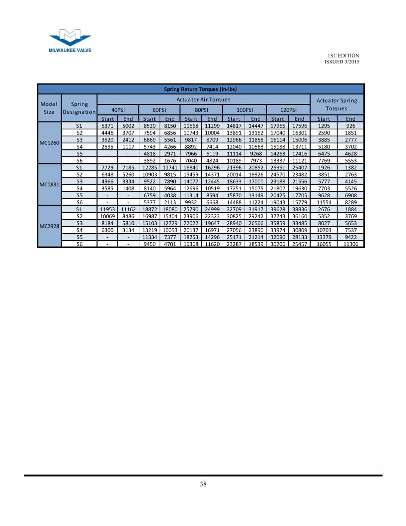
Spring Return Torques (in-lbs)
MC20
MC34
MC48
Model
Size
NOTE: For help with sizing contact Milwaukee Valve.
A.
B.
37
1ST EDITION ISSUED 3/2015
Start End Start End Start End Start End Start End Start EndS1 312 287 494 469 677 652 860 834 1042 1017 78 53S2 259 208 441 391 624 573 806 756 989 939 157 106S3 206 130 388 312 571 495 753 678 936 860 235 160S4 152 52 335 234 517 417 700 599 883 782 314 213S5 - - 282 156 464 338 647 521 829 703 392 266S6 - - 229 77 411 260 594 442 776 625 470 319S1 460 421 729 690 998 960 1267 1229 1536 1498 117 79S2 381 304 650 573 919 843 1189 1112 1458 1381 234 157S3 303 187 572 456 841 726 1110 995 1379 1264 351 236S4 224 70 493 339 762 609 1031 878 1301 1147 468 314S5 - - 415 222 684 492 953 761 1222 1030 585 393S6 - - 336 105 605 374 874 644 1143 913 702 471S1 673 611 1062 1001 1452 1391 1841 1780 2231 2170 168 107S2 566 444 956 833 1345 1223 1735 1612 2124 2002 335 213S3 459 276 849 666 1239 1055 1628 1445 2018 1834 503 320S4 353 109 742 498 1132 888 1522 1277 1911 1667 671 426S5 - - 636 330 1025 720 1415 1110 1805 1499 838 533S6 - - 529 163 919 552 1309 942 1698 1331 1006 639S1 1013 922 1608 1517 2202 2111 2797 2706 3392 3301 268 177S2 836 654 1431 1249 2026 1844 2620 2438 3215 3033 535 353S3 659 386 1254 981 1849 1576 2444 2171 3038 2765 803 530S4 483 119 1078 713 1672 1308 2267 1903 2862 2498 1071 707S5 - - 901 446 1496 1040 2090 1635 2685 2230 1339 883S6 - - 724 178 1319 773 1914 1367 2508 1962 1606 1060S1 1439 1282 2268 2111 3097 2940 3926 3769 4755 4598 376 219S2 1221 906 2050 1735 2879 2564 3708 3393 4537 4223 752 438S3 1002 531 1831 1360 2660 2189 3489 3018 4318 3847 1128 656S4 783 155 1612 984 2441 1813 3270 2642 4099 3471 1503 875S5 - - 1393 608 2222 1437 3051 2266 3880 3095 1879 1094S6 - - 1174 232 2004 1061 2833 1890 3662 2719 2255 1313S1 1745 1596 2763 2614 3780 3631 4797 4648 5815 5666 438 289S2 1456 1158 2473 2175 3491 3193 4508 4210 5525 5227 877 579S3 1166 720 2184 1737 3201 2754 4219 3772 5236 4789 1315 868S4 877 281 1894 1298 2912 2316 3929 3333 4946 4351 1754 1158S5 - - 1605 860 2622 1877 3640 2895 4657 3912 2192 1447S6 - - 1316 422 2333 1439 3350 2456 4368 3474 2630 1737S1 2680 2438 4255 4013 5829 5587 7404 7162 8979 8737 712 469S2 2210 1726 3785 3301 5360 4876 6935 6450 8509 8025 1423 939S3 1741 1014 3316 2589 4890 4164 6465 5739 8040 7313 2135 1408S4 1272 303 2846 1877 4421 3452 5996 5027 7570 6602 2847 1878S5 - - 2377 1166 3951 2741 5526 4315 7101 5890 3558 2347S6 - - 1907 454 3482 2029 5057 3604 6631 5178 4270 2817S1 4376 3998 6901 6523 9426 9047 11950 11572 14475 14097 1051 673S2 3703 2947 6228 5471 8753 7996 11277 10521 13802 13045 2103 1346S3 3030 1895 5555 4420 8080 6945 10604 9469 13129 11994 3154 2019S4 2357 844 4882 3368 7406 5893 9931 8418 12456 10943 4206 2692S5 - - 4209 2317 6733 4842 9258 7366 11783 9891 5257 3366S6 - - 3535 1266 6060 3790 8585 6315 11110 8840 6308 4039
Spring Return Torques (in-lbs)
MC1009
MC157
MC237
MC331
MC406
MC633
MC75
MC105
SizeSpring
Des ignation
Actuator Air Torques Actuator Spring
Torques40PSI 60PSI 80PSI 100PSI 120PSI
38
1ST EDITION ISSUED 3/2015
Start End Start End Start End Start End Start End Start EndS1 5371 5002 8520 8150 11668 11299 14817 14447 17965 17596 1295 926S2 4446 3707 7594 6856 10743 10004 13891 13152 17040 16301 2590 1851S3 3520 2412 6669 5561 9817 8709 12966 11858 16114 15006 3885 2777S4 2595 1117 5743 4266 8892 7414 12040 10563 15188 13711 5180 3702S5 - - 4818 2971 7966 6119 11114 9268 14263 12416 6475 4628S6 - - 3892 1676 7040 4824 10189 7973 13337 11121 7769 5553S1 7729 7185 12285 11741 16840 16296 21396 20852 25951 25407 1926 1382S2 6348 5260 10903 9815 15459 14371 20014 18926 24570 23482 3851 2763S3 4966 3334 9522 7890 14077 12445 18633 17000 23188 21556 5777 4145S4 3585 1408 8140 5964 12696 10519 17251 15075 21807 19630 7703 5526S5 - - 6759 4038 11314 8594 15870 13149 20425 17705 9628 6908S6 - - 5377 2113 9932 6668 14488 11224 19043 15779 11554 8289S1 11953 11162 18872 18080 25790 24999 32709 31917 39628 38836 2676 1884S2 10069 8486 16987 15404 23906 22323 30825 29242 37743 36160 5352 3769S3 8184 5810 15103 12729 22022 19647 28940 26566 35859 33485 8027 5653S4 6300 3134 13219 10053 20137 16971 27056 23890 33974 30809 10703 7537S5 - - 11334 7377 18253 14296 25171 21214 32090 28133 13379 9422S6 - - 9450 4701 16368 11620 23287 18539 30206 25457 16055 11306
Spring Return Torques (in-lbs)
MC1260
MC1831
MC2928
Model
Size
Spring
Des ignation
Actuator Air Torques Actuator Spring
Torques40PSI 60PSI 80PSI 100PSI 120PSI
39
1ST EDITION ISSUED 3/2015
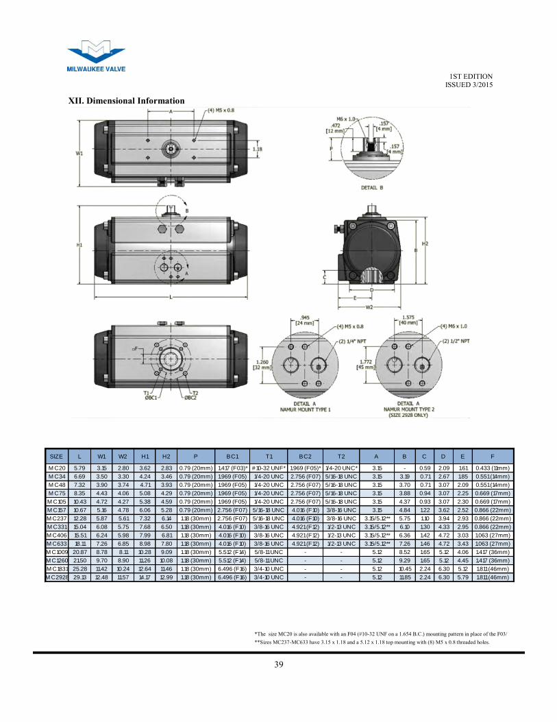
SIZE L W1 W2 H1 H2 P BC1 T1 BC2 T2 A B C D E F
M C20 5.79 3.15 2.80 3.62 2.83 0.79 (20mm) 1.417 (F03)* #10-32 UNF* 1.969 (F05)* 1/4-20 UNC* 3.15 - 0.59 2.09 1.61 0.433 (11mm)
M C34 6.69 3.50 3.30 4.24 3.46 0.79 (20mm) 1.969 (F05) 1/4-20 UNC 2.756 (F07) 5/16-18 UNC 3.15 3.19 0.71 2.67 1.85 0.551 (14mm)
M C48 7.32 3.90 3.74 4.71 3.93 0.79 (20mm) 1.969 (F05) 1/4-20 UNC 2.756 (F07) 5/16-18 UNC 3.15 3.70 0.71 3.07 2.09 0.551 (14mm)
M C75 8.35 4.43 4.06 5.08 4.29 0.79 (20mm) 1.969 (F05) 1/4-20 UNC 2.756 (F07) 5/16-18 UNC 3.15 3.88 0.94 3.07 2.25 0.669 (17mm)
M C105 10.43 4.72 4.27 5.38 4.59 0.79 (20mm) 1.969 (F05) 1/4-20 UNC 2.756 (F07) 5/16-18 UNC 3.15 4.37 0.93 3.07 2.30 0.669 (17mm)
M C157 10.67 5.16 4.78 6.06 5.28 0.79 (20mm) 2.756 (F07) 5/16-18 UNC 4.016 (F10) 3/8-16 UNC 3.15 4.84 1.22 3.62 2.52 0.866 (22mm)
M C237 12.28 5.87 5.61 7.32 6.14 1.18 (30mm) 2.756 (F07) 5/16-18 UNC 4.016 (F10) 3/8-16 UNC 3.15/5.12** 5.75 1.10 3.94 2.93 0.866 (22mm)
M C331 15.04 6.08 5.75 7.68 6.50 1.18 (30mm) 4.016 (F10) 3/8-16 UNC 4.921 (F12) 1/2-13 UNC 3.15/5.12** 6.10 1.30 4.33 2.95 0.866 (22mm)
M C406 15.51 6.24 5.98 7.99 6.81 1.18 (30mm) 4.016 (F10) 3/8-16 UNC 4.921 (F12) 1/2-13 UNC 3.15/5.12** 6.36 1.42 4.72 3.03 1.063 (27mm)
M C633 18.11 7.26 6.85 8.98 7.80 1.18 (30mm) 4.016 (F10) 3/8-16 UNC 4.921 (F12) 1/2-13 UNC 3.15/5.12** 7.26 1.46 4.72 3.43 1.063 (27mm)
M C1009 20.87 8.78 8.11 10.28 9.09 1.18 (30mm) 5.512 (F14) 5/8-11 UNC - - 5.12 8.52 1.65 5.12 4.06 1.417 (36mm)
M C1260 21.50 9.70 8.90 11.26 10.08 1.18 (30mm) 5.512 (F14) 5/8-11 UNC - - 5.12 9.29 1.65 5.12 4.45 1.417 (36mm)
M C1831 25.28 11.42 10.24 12.64 11.46 1.18 (30mm) 6.496 (F16) 3/4-10 UNC - - 5.12 10.45 2.24 6.30 5.12 1.811 (46mm)
M C2928 29.13 12.48 11.57 14.17 12.99 1.18 (30mm) 6.496 (F16) 3/4-10 UNC - - 5.12 11.85 2.24 6.30 5.79 1.811 (46mm)
*The size MC20 is also available with an F04 (#10-32 UNF on a 1.654 B.C.) mounting pattern in place of the F03/
XII. Dimensional Information
**Sizes MC237-MC633 have 3.15 x 1.18 and a 5.12 x 1.18 top mounting with (8) M5 x 0.8 threaded holes.
**
40
1ST EDITION ISSUED 3/2015
WA R R A N T Y
THE SELLER WARRANTS ITS PRODUCTS AGAINST DEFECTS IN
MATERIALS OR WORKMANKSHIP, WHEN USED ON THOSE SERVICES
APPROVED BY THE SELLER, FOR A PERIOD OF TWO YEARS FROM THE
DATE OF ORIGINAL SHIPMENT. THE SELLER’S LIABILITY UNDER THIS
WARRANTY SHALL BE LIMITED TO REPAIR OR REPLACEMENT AT
SELLER’S OPTION OF SUCH PRODUCTS. F.O.B. FACTORY, UPON PROOF OF
DEFECTS SATISFACTORY TO SELLER. SELLER MAKES NO WARRANTIES,
EITHER EXPRESSED OR IMPLIED, EXCEPT AS PROVIDED HEREIN,
INCLUDING WITHOUT LIMITATION THEREOF, WARRANTIES AS TO
MARKETABILITY, MERCHANTABILITY, FITNESS FOR A PARTICULAR
PURPOSE OR USE, OR AGAINST INFRINGMENT OF ANY PATENT. IN NO
EVENT SHALL SELLER BE LIABLE FOR ANY DIRECT, INCIDENTAL OR
CONSEQUENTIAL DAMAGES OF ANY NATURE, OR LOSES OR EXPENSES
RESULTING FROM ANY DEFECTIVE PRODUCTS OR THE USE OF ANY
PRODUCT.
For questions or more information, visit www.milwaukeevalve.com
Milwaukee Valve Company 16550 West Stratton Drive
New Berlin, Wisconsin 53151
Ph.: 262-432-2700
www.milwaukeevalve.com