installation manual my2002-2013 525hp efi · whipple charger installations instructions for mercury...
TRANSCRIPT

Whipple Charger Installations Instructions for Mercury Racing 525 HP EFI
525HP SC _V3R5 1 of 67
Installation Manual MY2002-2013 525HP EFI
WHIPPLE SUPERCHARGERS 3292 NORTH WEBER AVE
FRESNO, CA 93722 TEL 559.442.1261 FAX 559.442.4153
www.whipplesuperchargers.com A color PDF of this manual is available, email [email protected] for a copy
PREMIUM FUEL ONLY (91 OCTANE OR BETTER ALWAYS) RON+MON/2
Version A3R5 Last Updated April 17th, 2014

Whipple Charger Installations Instructions for Mercury Racing 525 HP EFI
525HP SC _V3R5 2 of 67
WHIPPLE SUPERCHARGER INSTALLATION MANUAL (MY2002-2013 525 HP EFI)
This product is intended for use on STOCK, UNMODIFIED, WELL-MAINTAINED ENGINES. Installation on a worn-out or modified engine is not recommended and could result in failure of the engine or the supercharger. It is recommended to perform a compression test of all cylinders, and perform a cylinder pressure leak down procedure. This will indicate the condition of the engine for reference. Whipple also highly recommends water block pressure and fuel pressure gauges for constant monitoring during operation. YOU MUST SEND YOUR ECU IN FOR REPROGRAMMING TO WORK WITH THE WHIPPLE SUPERCHARGER SYSTEM. ACCOMPANY EACH COMPUTER WITH NAME, SHIPPING INFORMATION, CONTACT INFO, BOAT INFO AND IF ANY MODIFICATIONS HAVE BEEN MADE TO THE ENGINE. SEND FACTORY ECU TO:
Ship to:
WHIPPLE SUPERCHARGERS ATTENTION: MARINE ECU RECAL DEPARTMENT
3292 N. WEBER FRESNO, CA 93722
559.442.1261
Whipple Charger Installations Instructions for Mercury Racing 525 HP EFI
525HP SC _V3R5 3 of 67
**NOTICE: Installation of Whipple Supercharger products signifies that you have read this document and have agreed to the terms stated w ithin. I t is the purchaser’s responsibility to follow all installation instruction guidelines and safety procedures supplied w ith the product as it is received by the purchaser to determine the compatibility of the product w ith the vessel or the device the purchaser intends to install the product on. Whipple Supercharger assumes no responsibility for damages occurring from accident, misuse, abuse, improper installation, improper operation, lack of reasonable care, or all previously stated reasons resulting from incompatibility w ith other manufacturers’ products. There are no warranties expressed, implied, for merchantability or fitness for engine failure, parts failure, any type of damage to vessel in any way, or reimbursement for labor or inconvenience. For best performance and continued reliability the following are MANDATORY. 1. USE ONLY PREMIUM GRADE FUEL (91 OCTANE OR BETTER). 2. ALWAYS LISTEN FOR ANY SIGN OF ENGINE KNOCKING, IF PRESENT DISCONTINUE USE
IMMEDIATELY. 3. DO NOT OPERATE ENGINE IN BOOST IF THE FUEL PRESSRUE IS BELOW THE PRESSURE SPECIFIED
BY WHIPPLE INDUSTRIES. 4. NEVER CHANGE COMPUTER CALIBRATION (Engine fuel, ignition timing, or the RPM limiter, nothing)!
THIS COMPLETE SUPERCHARGER SYSTEM IS DESIGNED AND ENGINEERED TO MAXIMUM PERFORMANCE FROM THE WHIPPLE CALIBRATION. MODIFICATIONS MAY CAUSE SERIOUS DAMAGE TO THE ENGINE.
WARNING! The most important precaution you must take with the WHIPPLE CHARGER is cleanliness. This supercharger is a high quality, close tolerance compressor that cannot be subjected to dirt or any type of foreign material. Foreign material entering the supercharger will automatically void all warranties. DO NOT remove the protective seal on the supercharger prior to installation.
WARNING!! CONSTANT ABUSE OF THE REV LIMITER WILL CAUSE SEVERE ENGINE FAILURE!!
Whipple Charger Installations Instructions for Mercury Racing 525 HP EFI
525HP SC _V3R5 4 of 67
GENERAL INFORMATION This system requires a major fuel system modification. Use extreme caution around the high flammable fuel and fuel vapors. Always wear appropriate safety goggles and gloves when required.
Always use caution around flammable liquids.
Run the engine before beginning installation of the kit until the fuel level is as close as possible to empty. Make sure that fuel tank does not have old gasoline and contains only fuel that is 91 octane or better before installing supercharger kit. If the octane of the fuel in the tank is old or unknown, drain the tank until empty and fill with 91-octane premium fuel or higher. You will be required to disconnect all of the wiring connectors. It is very helpful to tag all wires for future reference. Engines with serial numbers prior to 0M905000 (2003 model) will need a special power steering reservoir mount. PROPPING RPM RANGE The Whipple 525HP EFI system has a RPM limit of 6000rpm. The Smartcraft Overspeed warning comes on at 5800 to let you know you are near max RPM. While the 525HP EFI motor continues to make power at this rpm level, maximum engine life will be from 5600-5800 max propping rpm. Short burst above 5600rpm will not be a problem, but prolong abuse of this rpm will shorten engine life, most noticeably valve train life. RECOMMENDED PREPERATION FOR INSTALL It’s mandatory that you replace the factory spark plugs (NGK BPR6ES) with a minimum of NGK R5671-A8. Proper spark plug gap is .035”. Failure to replace spark plugs to the colder NGK could result in engine failure. TOOLS RECOMMENDED The following tools are required to complete the installation of this supercharger kit. Metric socket set, standard socket set, screwdrivers, torx head sockets, standard and metric end wrenches, standard and metric Allen wrenches, blue and red LoctiteTM, Teflon tape or thread sealant, electric or battery operated drill motor, various hole saws, electrical tape, wire crimpers or solder iron, 0-60 lb. fuel PSI gauge with line kit and a torque wrench. EXTRA PARTS REQUIRED This system requires a new fuel system, we have supplied you with the appropriate male fuel fittings but you will be required to manufacture some fuel lines. Whipple recommends high grade, USGC approved lines only. This system also requires a new intercooler pickup to be installed, a sea-strainer is recommended. Whipple cannot supply intercooler pickups due to the various boat designs. Consult the boat manufacture for the best location and style to produce as much water flow as possible. You must never run smaller than a 5/8” ID line to the intercooler. If running a strainer, you should run a larger line to the strainer, as this will be a restriction. Max PSI in the intercooler is 50psi which will be very difficult to reach with Whipple designed inlet fittings. You do not want to run the intercooler tee’d off the sea pump line, this will rob water from the engine and will lower overall reliability.
Whipple Charger Installations Instructions for Mercury Racing 525 HP EFI
525HP SC _V3R5 5 of 67
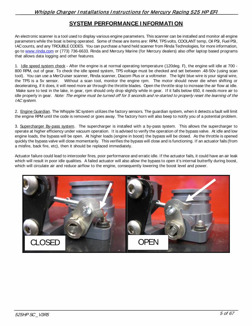
SYSTEM PERFORMANCE INFORMATION An electronic scanner is a tool used to display various engine parameters. This scanner can be installed and monitor all engine parameters while the boat is being operated. Some of these are items are: RPM, TPS volts, COOLANT temp, Oil PSI, Fuel PSI, IAC counts, and any TROUBLE CODES. You can purchase a hand held scanner from Rinda Technologies, for more information, go to www.rinda.com or (773) 736-6633. Rinda and Mercury Marine (for Mercury dealers) also offer laptop based programs that allows data logging and other features. 1. Idle speed system check - After the engine is at normal operating temperature (120deg. F), the engine will idle at 700 - 800 RPM, out of gear. To check the idle speed system, TPS voltage must be checked and set between .48-50v (using scan tool). You can use a MerCruiser scanner, Rinda scanner, Diacom Plus or a voltmeter. The light blue wire is your signal wire, the TPS is a 5v sensor. Without a scan tool, monitor the engine rpm. The motor should never die when shifting or decelerating, if it does, it will need more air through the throttle blades. Open the throttle stop to increase the air flow at idle. Make sure to test in the lake, in gear, rpm should only drop slightly while in gear. If it falls below 650, it needs more air to idle properly in gear. Note: The engine must be turned off for 5 seconds and re-started to properly reset the learning of the IAC system. 2. Engine Guardian. The Whipple SC system utilizes the factory sensors. The guardian system, when it detects a fault will limit the engine RPM until the code is removed or goes away. The factory horn will also beep to notify you of a potential problem. 3. Supercharger By-pass system. The supercharger is installed with a by-pass system. This allows the supercharger to operate at higher efficiency under vacuum operation. It is advised to verify the operation of the bypass valve. At idle and low engine loads, the bypass will be open. At higher loads (engine in boost) the bypass will be closed. As the throttle is opened quickly the bypass valve will close momentarily. This verifies the bypass will close and is functioning. If an actuator fails (from a misfire, back fire, etc), then it should be replaced immediately. Actuator failure could lead to intercooler fires, poor performance and erratic idle. If the actuator fails, it could have an air leak which will result in poor idle qualities. A failed actuator will also allow the bypass to open it’s internal butterfly during boost, which will circulate air and reduce airflow to the engine, consequently lowering the boost level and power.
CLOSED OPEN
Whipple Charger Installations Instructions for Mercury Racing 525 HP EFI
525HP SC _V3R5 6 of 67
TOP PORT
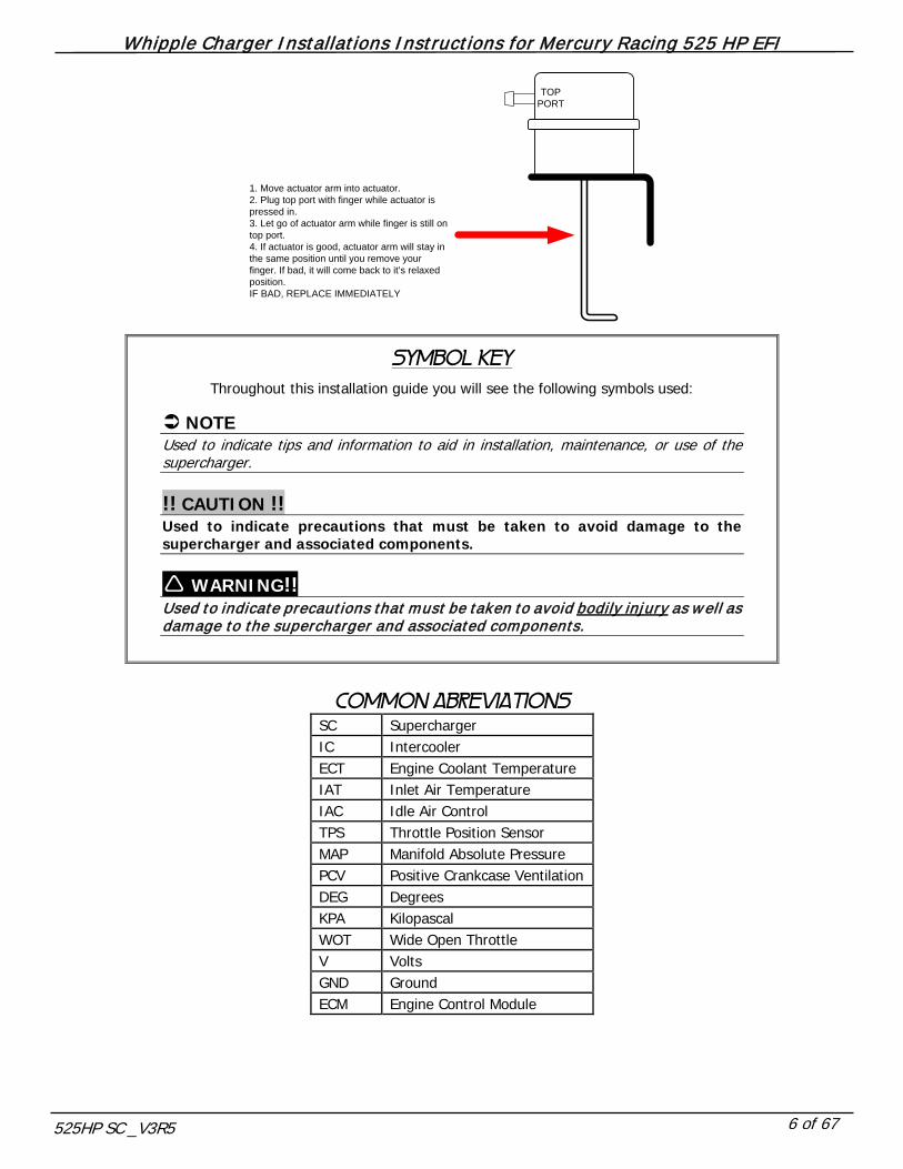
1. Move actuator arm into actuator.2. Plug top port with finger while actuator is pressed in.3. Let go of actuator arm while finger is still on top port.4. If actuator is good, actuator arm will stay in the same position until you remove your finger. If bad, it will come back to it’s relaxed position. IF BAD, REPLACE IMMEDIATELY
SYMBOL KEY
Throughout this installation guide you will see the following symbols used:
NOTE Used to indicate tips and information to aid in installation, maintenance, or use of the supercharger. !! CAUTION !! Used to indicate precautions that must be taken to avoid damage to the supercharger and associated components. WARNING!! Used to indicate precautions that must be taken to avoid bodily injury as well as damage to the supercharger and associated components.
COMMON ABREVIATIONS
SC Supercharger IC Intercooler ECT Engine Coolant Temperature IAT Inlet Air Temperature IAC Idle Air Control TPS Throttle Position Sensor MAP Manifold Absolute Pressure PCV Positive Crankcase Ventilation DEG Degrees KPA Kilopascal WOT Wide Open Throttle V Volts GND Ground ECM Engine Control Module

Whipple Charger Installations Instructions for Mercury Racing 525 HP EFI
525HP SC _V3R5 7 of 67
1. Turn the key to the on position. Using a scan tool, verify the TPS voltage and record _____________volts. If you do not have a scan tool, use a volt meter, probe the light blue wire in pin C of the TPS connector, record your finding ____________volts. The new Whipple throttle body will need to be set at the same voltage.
2. Disconnect the battery power by selecting the disconnect mode on the battery switch or removing the ground cable from
all batteries. 3. Remove the factory pipe plug just below the factory heat exchanger. This will drain the coolant just below the
thermostat level. Save coolant for later use.
4. Loosen the 5/8” locking nut on adjustment stud on the grooved factory idler pulley. Loosen the stud using a 5/16” socket
to release the belt tension. Remove 6-rib belt from engine.
Whipple Charger Installations Instructions for Mercury Racing 525 HP EFI
525HP SC _V3R5 8 of 67
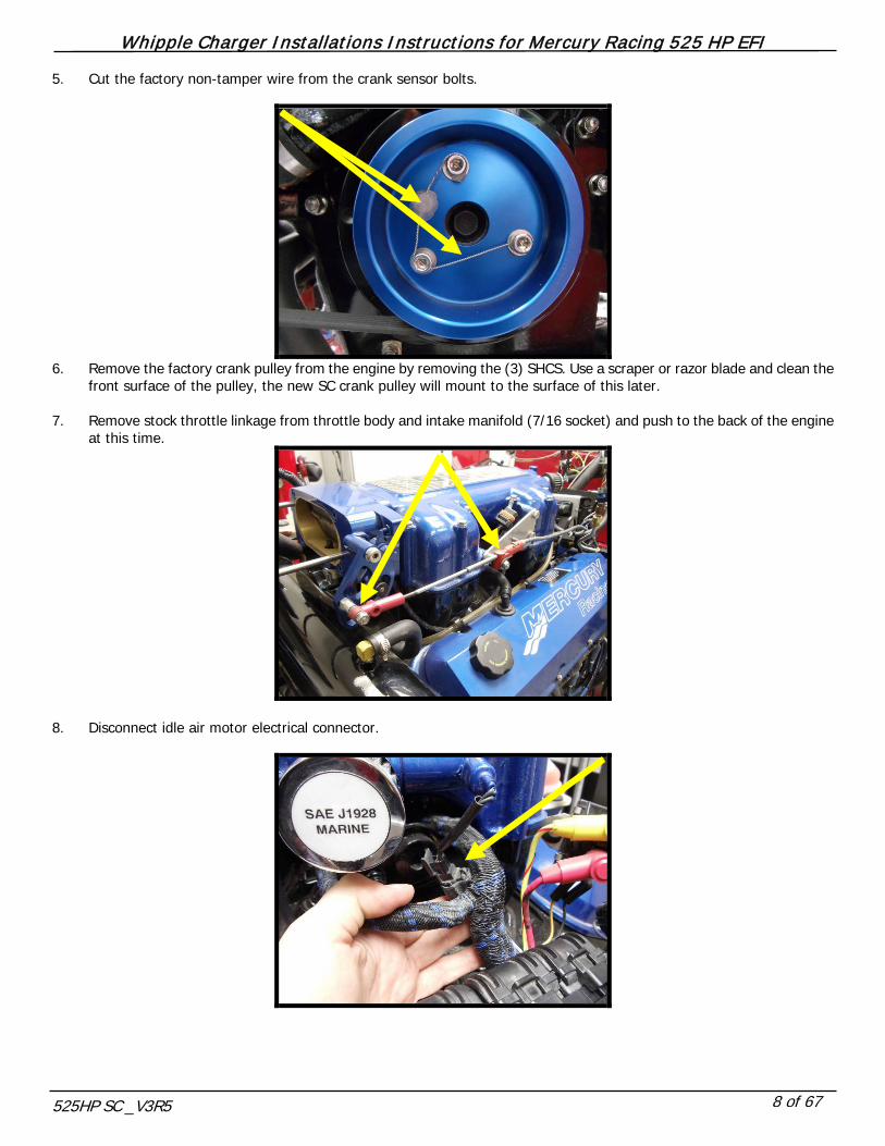
5. Cut the factory non-tamper wire from the crank sensor bolts.
6. Remove the factory crank pulley from the engine by removing the (3) SHCS. Use a scraper or razor blade and clean the
front surface of the pulley, the new SC crank pulley will mount to the surface of this later. 7. Remove stock throttle linkage from throttle body and intake manifold (7/16 socket) and push to the back of the engine
at this time.
8. Disconnect idle air motor electrical connector.

Whipple Charger Installations Instructions for Mercury Racing 525 HP EFI
525HP SC _V3R5 9 of 67
9. Remove IAC motor from intake plenum by removing the 2 button head allen bolts (4mm allen).
10. Disconnect factory MAP sensor connector from MAP sensor.
11. Disconnect factory throttle position sensor (TPS) 3-way connector.

Whipple Charger Installations Instructions for Mercury Racing 525 HP EFI
525HP SC _V3R5 10 of 67
12. Disconnect factory inlet air temp sensor (IAT) 2-way connector and remove sensor from engine.
13. Disconnect shift position switch from factory shift bracket. 14. Remove stock shifter bracket assembly from engine (7/16” socket), this will be remote mounted later. 15. Remove factory intake plenum by removing the 12 hex-head bolts (7/16” socket). 16. (Early model) Disconnect factory cam position sensor located in the standard distributor location. 17. (Early model) Crank engine of so #1 cylinder is at TDC. Remove cam sensor cap by removing the (2) torx bolts. Mark the
cam sensor base using a sharpie or grease pencil for later installation reference. Its ideal to mark the front, center for easy reference.
18. (Early model) Remove cam sensor from engine by removing the distributor clamp (9/16” wrench). 19. (Late model) Remove the distributor spud from the back of the engine by removing the distributor clamp (9/16” wrench)

Whipple Charger Installations Instructions for Mercury Racing 525 HP EFI
525HP SC _V3R5 11 of 67
20. (Late model) Disconnect factory cam position sensor located on the front of the engine, port side, below the circulating water pump, in the timing chain cover. Loosen adel clamp holding the cam sensor wires to engine, this will be pushed back at a later time.
21. Disconnect factory crank sensor electrical connector from engine.
22. Disconnect factory engine coolant sensor (ECT) 2-way connector.

Whipple Charger Installations Instructions for Mercury Racing 525 HP EFI
525HP SC _V3R5 12 of 67
23. Disconnect factory electric fuel pump 2-way connector.
24. (Late model) Remove factory relays (2) from front relay bracket. Remove relays from tab by lifting up.
25. Remove 50-amp breaker from relay bracket (this will be relocated later) by removing the (2) bolts (1/4” and 5/16”
wrenches).
Whipple Charger Installations Instructions for Mercury Racing 525 HP EFI
525HP SC _V3R5 13 of 67
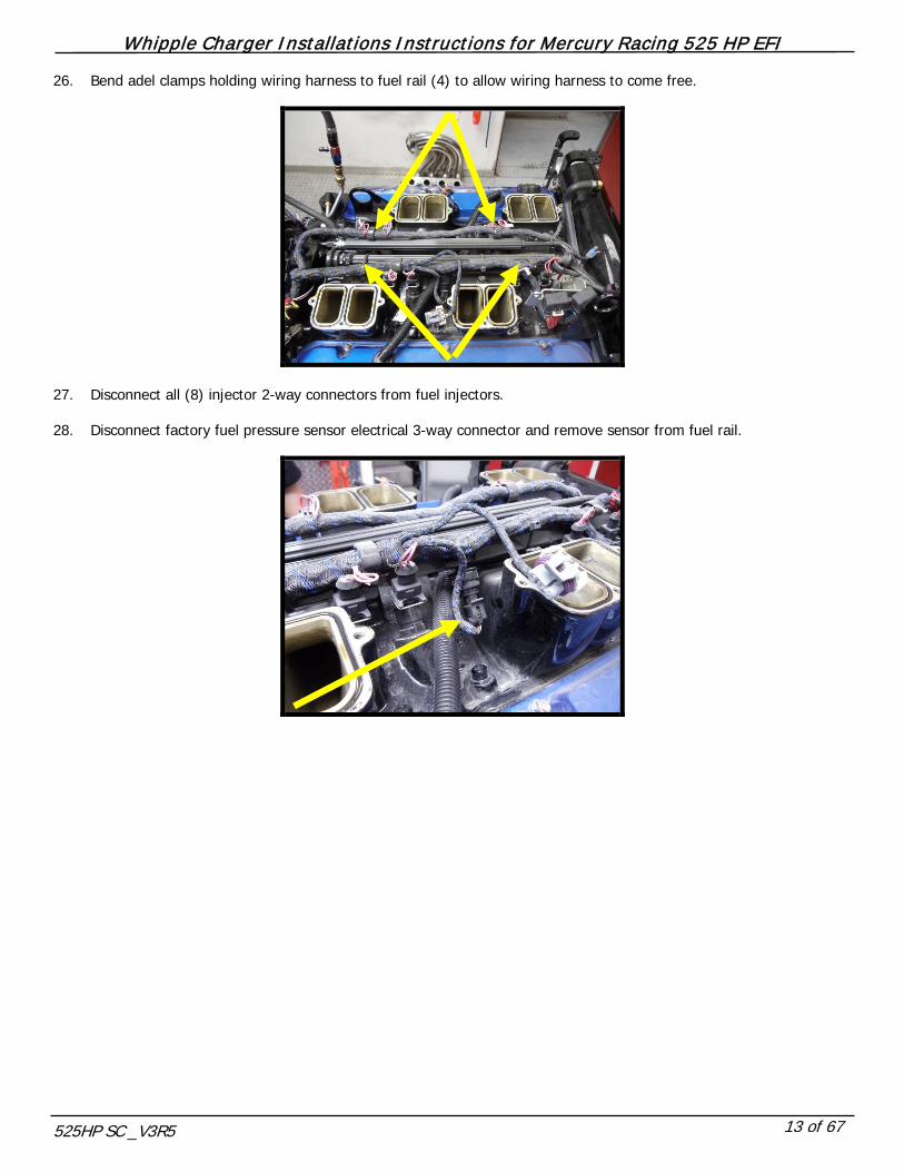
26. Bend adel clamps holding wiring harness to fuel rail (4) to allow wiring harness to come free.
27. Disconnect all (8) injector 2-way connectors from fuel injectors. 28. Disconnect factory fuel pressure sensor electrical 3-way connector and remove sensor from fuel rail.

Whipple Charger Installations Instructions for Mercury Racing 525 HP EFI
525HP SC _V3R5 14 of 67
29. Remove the factory fuel lines (3) from the fuel filter head.
FUEL IS UNDER PRESSURE!! Be very careful while removing the fuel rail bolts as fuel may be released under pressure. Prevent fuel spray by covering the injectors w ith a shop towel while the bolts are being loosened.
30. Remove the factory fuel filter head and element from engine by removing the (2) SHCS bolts.
31. Remove mechanical fuel pump from sea pump. Install chrome block off plate (and gasket) with supplied (2) – 3/8” x ¾”
stainless allen bolts and AN washers.

Whipple Charger Installations Instructions for Mercury Racing 525 HP EFI
525HP SC _V3R5 15 of 67
32. Remove the factory fuel lines from the factory billet filter located on the rear port side of cylinder head. Remove the filter and its mount from the engine.
33. Remove the 1 ¼” water inlet hose to the cool fuel assembly by removing the hose clamp that secures it the fuel cooler.
Also loosen the adel clamp holding the hose to the fuel pump assembly bracket.
34. Remove the 1 ¼” water outlet hose from the cool fuel pump assembly by removing the hose clamp.
Whipple Charger Installations Instructions for Mercury Racing 525 HP EFI
525HP SC _V3R5 16 of 67
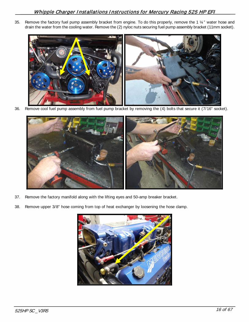
35. Remove the factory fuel pump assembly bracket from engine. To do this properly, remove the 1 ¼” water hose and drain the water from the cooling water. Remove the (2) nyloc nuts securing fuel pump assembly bracket (11mm socket).
36. Remove cool fuel pump assembly from fuel pump bracket by removing the (4) bolts that secure it (7/16” socket).
37. Remove the factory manifold along with the lifting eyes and 50-amp breaker bracket. 38. Remove upper 3/8” hose coming from top of heat exchanger by loosening the hose clamp.
Whipple Charger Installations Instructions for Mercury Racing 525 HP EFI
525HP SC _V3R5 17 of 67
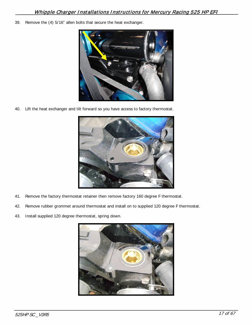
39. Remove the (4) 5/16” allen bolts that secure the heat exchanger.
40. Lift the heat exchanger and tilt forward so you have access to factory thermostat.
41. Remove the factory thermostat retainer then remove factory 160 degree F thermostat. 42. Remove rubber grommet around thermostat and install on to supplied 120 degree F thermostat. 43. Install supplied 120 degree thermostat, spring down.

Whipple Charger Installations Instructions for Mercury Racing 525 HP EFI
525HP SC _V3R5 18 of 67
44. Reinstall heat exchanger, allen bolts (4) and 3/8” hose. 45. (Late model) Loosen or remove the 2 nuts holding the factory PCM bracket from the back of the engine for better
access.
46. (Late model) Pull wiring harness from the front of the engine, to the back of the engine to have easy access for
modifying.
Whipple Charger Installations Instructions for Mercury Racing 525 HP EFI
525HP SC _V3R5 19 of 67
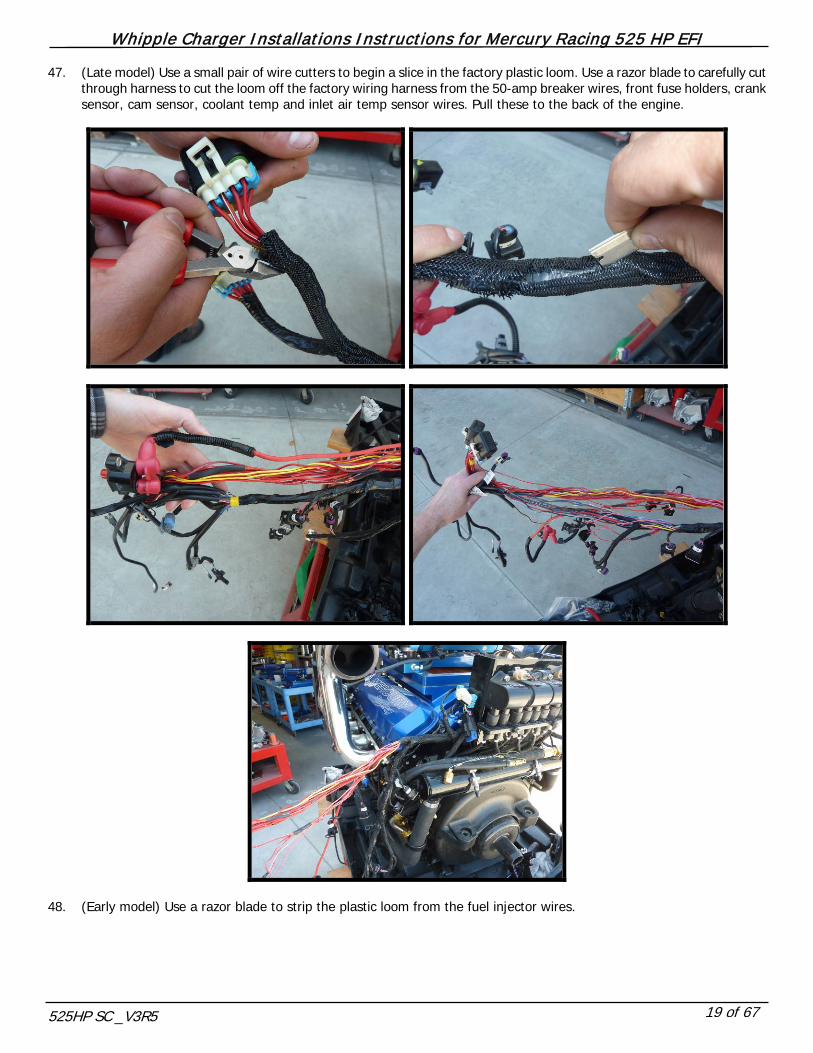
47. (Late model) Use a small pair of wire cutters to begin a slice in the factory plastic loom. Use a razor blade to carefully cut through harness to cut the loom off the factory wiring harness from the 50-amp breaker wires, front fuse holders, crank sensor, cam sensor, coolant temp and inlet air temp sensor wires. Pull these to the back of the engine.
48. (Early model) Use a razor blade to strip the plastic loom from the fuel injector wires.

Whipple Charger Installations Instructions for Mercury Racing 525 HP EFI
525HP SC _V3R5 20 of 67
49. Use the supplied injector pigtail to connect the factory wires to the new supplied pigtail. First connect the red and pink wires coming from pins K and J. Strip both ends of the wire, twist the ends together. Insert strip ends into blue heat shrink connector and crimp together.
50. Find the factory injector power wire, which is a 14ga red wire with a white trace. This wire is spliced 7 times for feeding
all 8 injectors so follow it past each splice point (wire goes to fuse block pin H, 20amp). Strip the end of this wire, twist the end and install into other end of blue heat shrink style butt connector. Crimp together and use heat gun to carefully shrink and seal butt connector.
Whipple Charger Installations Instructions for Mercury Racing 525 HP EFI
525HP SC _V3R5 21 of 67
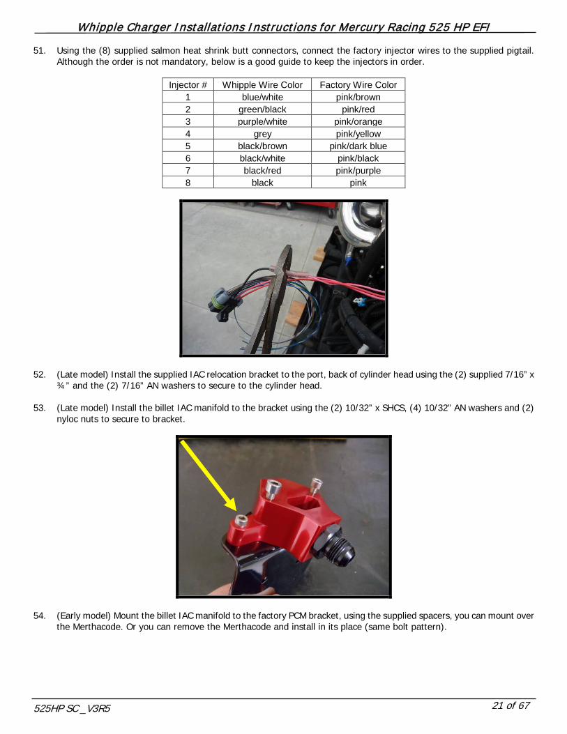
51. Using the (8) supplied salmon heat shrink butt connectors, connect the factory injector wires to the supplied pigtail. Although the order is not mandatory, below is a good guide to keep the injectors in order.
Injector # Whipple Wire Color Factory Wire Color
1 blue/white pink/brown 2 green/black pink/red 3 purple/white pink/orange 4 grey pink/yellow 5 black/brown pink/dark blue 6 black/white pink/black 7 black/red pink/purple 8 black pink
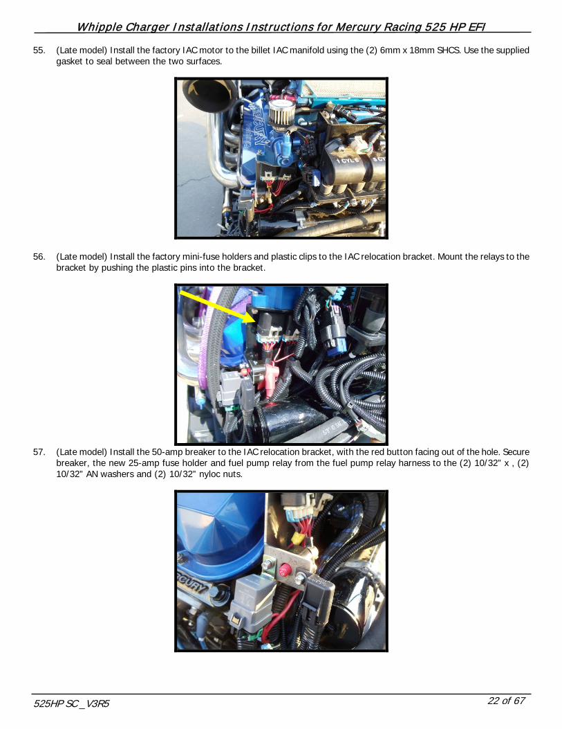
52. (Late model) Install the supplied IAC relocation bracket to the port, back of cylinder head using the (2) supplied 7/16” x ¾” and the (2) 7/16” AN washers to secure to the cylinder head.
53. (Late model) Install the billet IAC manifold to the bracket using the (2) 10/32” x SHCS, (4) 10/32” AN washers and (2)
nyloc nuts to secure to bracket.
54. (Early model) Mount the billet IAC manifold to the factory PCM bracket, using the supplied spacers, you can mount over
the Merthacode. Or you can remove the Merthacode and install in its place (same bolt pattern).
Whipple Charger Installations Instructions for Mercury Racing 525 HP EFI
525HP SC _V3R5 22 of 67
55. (Late model) Install the factory IAC motor to the billet IAC manifold using the (2) 6mm x 18mm SHCS. Use the supplied gasket to seal between the two surfaces.
56. (Late model) Install the factory mini-fuse holders and plastic clips to the IAC relocation bracket. Mount the relays to the bracket by pushing the plastic pins into the bracket.
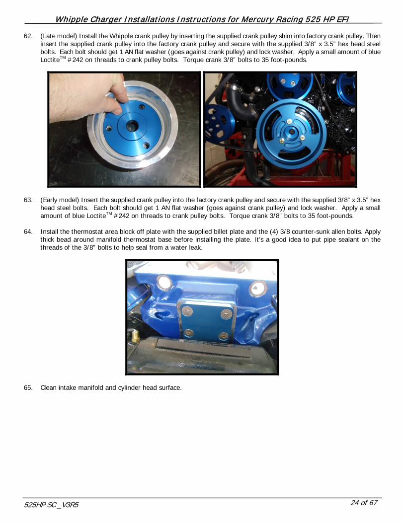
57. (Late model) Install the 50-amp breaker to the IAC relocation bracket, with the red button facing out of the hole. Secure
breaker, the new 25-amp fuse holder and fuel pump relay from the fuel pump relay harness to the (2) 10/32” x , (2) 10/32” AN washers and (2) 10/32” nyloc nuts.

Whipple Charger Installations Instructions for Mercury Racing 525 HP EFI
525HP SC _V3R5 23 of 67
58. (Late model) Use the supplied black 18awg wires, and (4) salmon heat-shrink butt connectors to extend the factory IAC wires roughly 10”-14”. Once you’ve crimped the butt connectors, use a heat gun to shrink and seal the butt connectors. Be cautious to not damage the wires or cross the wires. Apply supplied plastic split loom to cover exposed wire and butt connectors.
59. (Late model) Install the supplied plastic loom over the mini-fuse holder wires and 50-amp breaker wires. Curl these wires
up behind the oil cooler, secure with a zip-tie. 60. Route the coolant temp, crank position and cam position (late model) forward, down the port side valve cover. Tuck
between the intake manifold and valve cover using factory adel clamps. Connect coolant temp, crank position and cam position (late model) connectors to sensors. Use factory adel clamps to hold wires away from factory belt system.
61. Clean the front surface of the factory crank pulley with a gasket scraper or razor blade.
Whipple Charger Installations Instructions for Mercury Racing 525 HP EFI
525HP SC _V3R5 24 of 67
62. (Late model) Install the Whipple crank pulley by inserting the supplied crank pulley shim into factory crank pulley. Then insert the supplied crank pulley into the factory crank pulley and secure with the supplied 3/8” x 3.5” hex head steel bolts. Each bolt should get 1 AN flat washer (goes against crank pulley) and lock washer. Apply a small amount of blue LoctiteTM #242 on threads to crank pulley bolts. Torque crank 3/8” bolts to 35 foot-pounds.
63. (Early model) Insert the supplied crank pulley into the factory crank pulley and secure with the supplied 3/8” x 3.5” hex
head steel bolts. Each bolt should get 1 AN flat washer (goes against crank pulley) and lock washer. Apply a small amount of blue LoctiteTM #242 on threads to crank pulley bolts. Torque crank 3/8” bolts to 35 foot-pounds.
64. Install the thermostat area block off plate with the supplied billet plate and the (4) 3/8 counter-sunk allen bolts. Apply
thick bead around manifold thermostat base before installing the plate. It’s a good idea to put pipe sealant on the threads of the 3/8” bolts to help seal from a water leak.
65. Clean intake manifold and cylinder head surface.
Whipple Charger Installations Instructions for Mercury Racing 525 HP EFI
525HP SC _V3R5 25 of 67
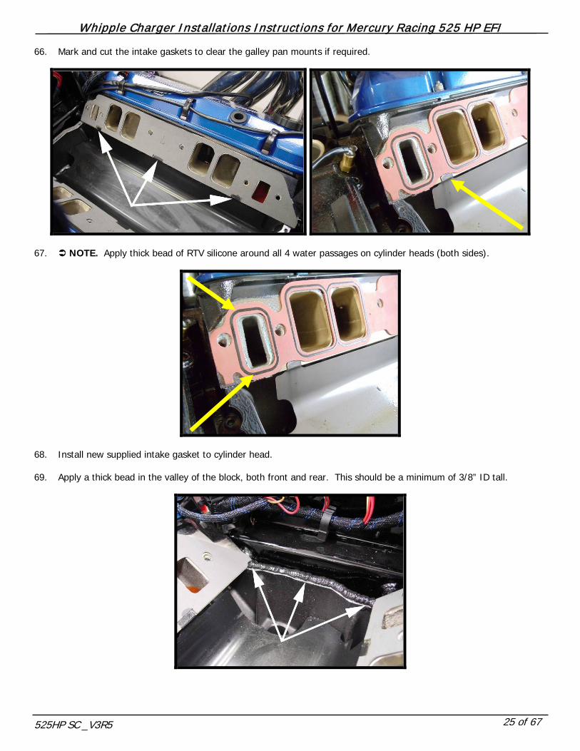
66. Mark and cut the intake gaskets to clear the galley pan mounts if required.
67. NOTE. Apply thick bead of RTV silicone around all 4 water passages on cylinder heads (both sides).
68. Install new supplied intake gasket to cylinder head. 69. Apply a thick bead in the valley of the block, both front and rear. This should be a minimum of 3/8” ID tall.

Whipple Charger Installations Instructions for Mercury Racing 525 HP EFI
525HP SC _V3R5 26 of 67
70. Install intake manifold using the (11) – 3/8” x 1.5” socket head allens, (1) 3/8” x 1.5” hex head bolt and the .680” stainless washers. Utilize the hex head bolt in the forward most bolt on the inside of intake, see figure (above #2 cylinder). Torque bolts to 35 foot-pounds. !! CAUTION !! Note: Install all bolts hand tight and align intake runners as much as possible.
71. Install supplied oring to manifold-to-intercooler flange surface (.139” x 50.75”). Apply a light amount of marine style
grease to oring surface; follow by pushing the oring into its receiver groove. Once completed, apply some more marine type grease to oring surface.
72. Install the supplied black oring (2 for stage 1, 4 for stage 2) to the front face of the intercooler core. Apply light amount
of marine type grease to orings to help from ripping and to hold in place.
73. Carefully install intercooler core into intake manifold. Take the two –12AN stainless water fittings (1 short, one long),
apply light amount of marine type grease around green oring, apply pipe sealant to threads and install into intercooler core evenly. Short fitting goes on port side, long on starboard side. (Stage 2 leave the fittings loose until next step) Do not tighten one while one is loose, this could cause the core to go in unevenly.
74. (Stage 2) Install the supplied .139” x 47.91” oring to the bottom of the 1.25” spacer plate. Install the supplied 1.25” spacer ring to the intercooler core and manifold. Install the supplied green oring to the IC fitting, apply light amount of grease to oring. Install the supplied 2 long intercooler fittings into spacer. Tighten all 4 stainless IC fittings evenly. This must be done before the SC is installed and tightened otherwise the spacer will not seal.

Whipple Charger Installations Instructions for Mercury Racing 525 HP EFI
525HP SC _V3R5 27 of 67
75. Install factory inlet air temp sensor into open 3/8” NPT hole in rear/port side of intake manifold (with pipe sealant on threads).
76. Connect the factory 2-way air temp sensor connector to the air temp sensor.
77. Install the supplied 3-way MAP sensor pigtail (flat to round) to the factory map sensor connector. Connect the round end
into the pre-installed 2-bar map sensor at the back of the intake manifold.
78. Install supplied .139” x 47.91” oring to supercharger adapter plate. Apply a light amount of marine style grease to oring surface; follow by pushing the oring into its receiver groove.
79. Install supercharger assembly by lying on intake manifold. Install the (8) 7/16” SHCS bolts and torque to 35 ft. lbs.
Whipple Charger Installations Instructions for Mercury Racing 525 HP EFI
525HP SC _V3R5 28 of 67
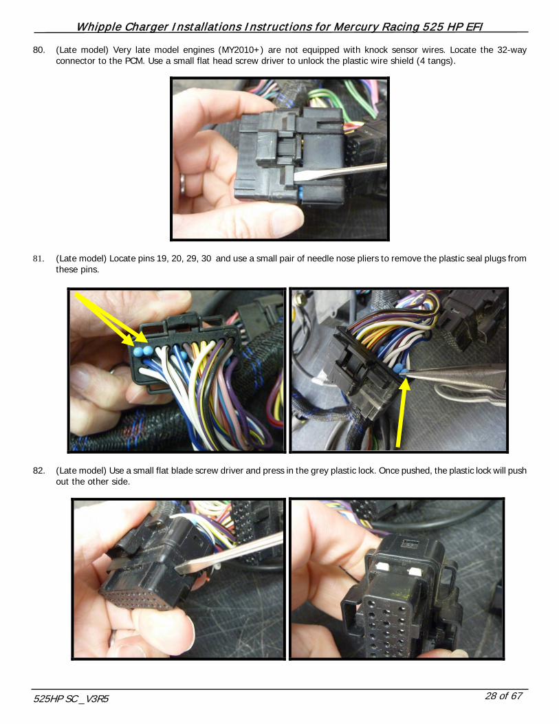
80. (Late model) Very late model engines (MY2010+) are not equipped with knock sensor wires. Locate the 32-way connector to the PCM. Use a small flat head screw driver to unlock the plastic wire shield (4 tangs).
81. (Late model) Locate pins 19, 20, 29, 30 and use a small pair of needle nose pliers to remove the plastic seal plugs from
these pins.
82. (Late model) Use a small flat blade screw driver and press in the grey plastic lock. Once pushed, the plastic lock will push
out the other side.

Whipple Charger Installations Instructions for Mercury Racing 525 HP EFI
525HP SC _V3R5 29 of 67
83. (Late model) Insert new, supplied pins into 32-way connector as shown in the diagram.
Smartcraft PCM555
17
1 2
9
18
10
19
3
11
20
4
12
5
21
13
6
22
14
23
7
15
8
24
16
17
1 2
9
18
10
19
3
11
20
4
12
5
21
13
6
22
14
23
7
15
8
24
16
22
1 2
12
23
13
24
3
14
25
4
15
5
26
16
6
27
17
28
7
18
8
29
19
9
30
20
31
10
21
11
32
ABC
CONNECTOR APIN DESCRIPTION
1 Key on Power2 Empty3 Map Sensor Connector Pin B4 Oil Pressure Sensor Connector Pin C5 Pitot Pressure Sensor S/T Con Pin D6 Throttle Position Sensor Con Pin C7 Empty8 Trim Position Smart Trans Con Pin C9 Starboard Tab Position Tab Con Pin A
10 Port Tab Position Tab Connector Pin B11 CAN Line Pos (+) Connector Pin J12 Steering Position Smart Trans Con Pin E13 Seawater Temp Paddle Wheel Con Pin D14 MAT Sensor Connector Pin B15 Coolant Temp Sensor Connector Pin B16 Port Exhaust Water Temp Con Pin B17 Starboard Exhaust Water Temp con Pin B18 Data Link Connector Pin C19 Port Knock Sensor Connector Pin B20 Starboard Knock Sensor Con Pin A21 CAN Line Neg (-) Connector Pin K22 Splice 10023 Splice 10124 Seapump Pressure Connector Pin C25 Fuel Level Connector Pin C62 Fuel Level Connector Pin B27 Empty28 Data Link Connector Pin B29 Port Knock Sensor Connector Pin A30 Starboarb Knock Connector Pin B31 CAN2 Line Pos(+) connector Pin G32 CAN2 Line Neg(-) Connector Pin H
22
1 2
12
23
13
24
3
14
25
4
15
5
26
16
6
27
17
28
7
18
8
29
19
9
30
20
31
10
21
11
32
BK/RED
BK/WHWH/BK
WH/BK
B
A
A
B
Port Knock Sensor
Starboard Knock Sensor
Whipple Charger Installations Instructions for Mercury Racing 525 HP EFI
525HP SC _V3R5 30 of 67
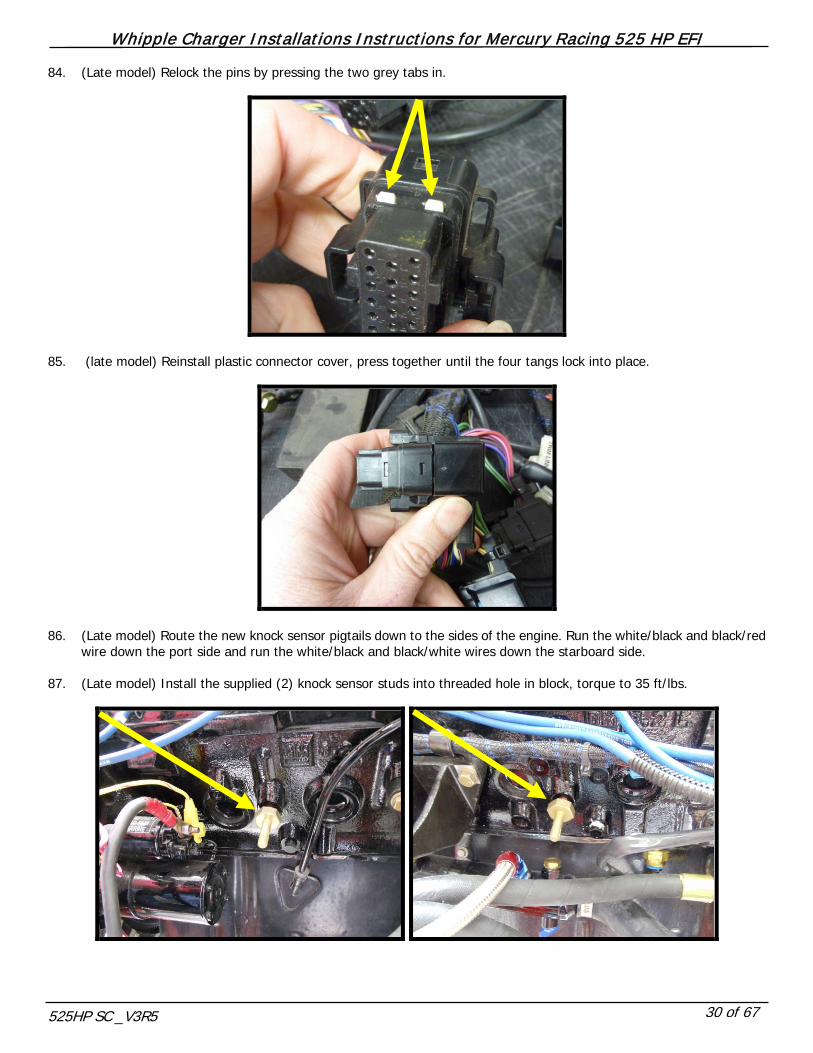
84. (Late model) Relock the pins by pressing the two grey tabs in.
85. (late model) Reinstall plastic connector cover, press together until the four tangs lock into place.
86. (Late model) Route the new knock sensor pigtails down to the sides of the engine. Run the white/black and black/red
wire down the port side and run the white/black and black/white wires down the starboard side. 87. (Late model) Install the supplied (2) knock sensor studs into threaded hole in block, torque to 35 ft/lbs.

Whipple Charger Installations Instructions for Mercury Racing 525 HP EFI
525HP SC _V3R5 31 of 67
88. (Late model) Slide sensor over stud and secure with stainless nut and AN washer, torque to 25 ft/lbs. Wire connection should face towards back of engine.
89. (Late model) Connect the knock sensor 2-way connector to factory knock sensor connectors.
90. Install factory fuel psi sensor into 1/8” port in back of Whipple SC fuel rail. Apply light amount of pipe sealant to threads.
Whipple Charger Installations Instructions for Mercury Racing 525 HP EFI
525HP SC _V3R5 32 of 67
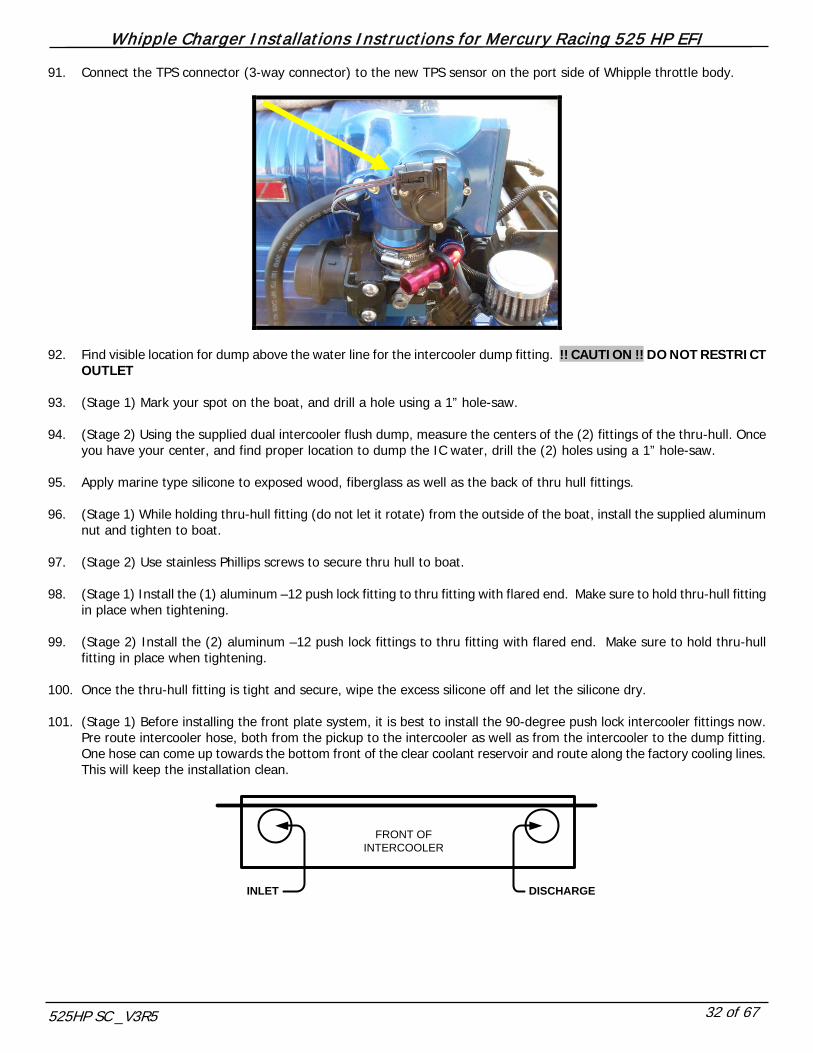
91. Connect the TPS connector (3-way connector) to the new TPS sensor on the port side of Whipple throttle body.
92. Find visible location for dump above the water line for the intercooler dump fitting. !! CAUTION !! DO NOT RESTRICT
OUTLET 93. (Stage 1) Mark your spot on the boat, and drill a hole using a 1” hole-saw. 94. (Stage 2) Using the supplied dual intercooler flush dump, measure the centers of the (2) fittings of the thru-hull. Once
you have your center, and find proper location to dump the IC water, drill the (2) holes using a 1” hole-saw. 95. Apply marine type silicone to exposed wood, fiberglass as well as the back of thru hull fittings. 96. (Stage 1) While holding thru-hull fitting (do not let it rotate) from the outside of the boat, install the supplied aluminum
nut and tighten to boat. 97. (Stage 2) Use stainless Phillips screws to secure thru hull to boat. 98. (Stage 1) Install the (1) aluminum –12 push lock fitting to thru fitting with flared end. Make sure to hold thru-hull fitting
in place when tightening. 99. (Stage 2) Install the (2) aluminum –12 push lock fittings to thru fitting with flared end. Make sure to hold thru-hull
fitting in place when tightening. 100. Once the thru-hull fitting is tight and secure, wipe the excess silicone off and let the silicone dry. 101. (Stage 1) Before installing the front plate system, it is best to install the 90-degree push lock intercooler fittings now.
Pre route intercooler hose, both from the pickup to the intercooler as well as from the intercooler to the dump fitting. One hose can come up towards the bottom front of the clear coolant reservoir and route along the factory cooling lines. This will keep the installation clean.
INLET DISCHARGE
FRONT OF INTERCOOLER
Whipple Charger Installations Instructions for Mercury Racing 525 HP EFI
525HP SC _V3R5 33 of 67
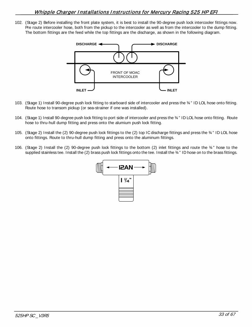
102. (Stage 2) Before installing the front plate system, it is best to install the 90-degree push lock intercooler fittings now. Pre route intercooler hose, both from the pickup to the intercooler as well as from the intercooler to the dump fitting. The bottom fittings are the feed while the top fittings are the discharge, as shown in the following diagram.
INLET
DISCHARGE DISCHARGE
INLET
FRONT OF MOAC INTERCOOLER
103. (Stage 1) Install 90-degree push lock fitting to starboard side of intercooler and press the ¾” ID LOL hose onto fitting.
Route hose to transom pickup (or sea-strainer if one was installed). 104. (Stage 1) Install 90-degree push lock fitting to port side of intercooler and press the ¾” ID LOL hose onto fitting. Route
hose to thru-hull dump fitting and press onto the alumium push lock fitting. 105. (Stage 2) Install the (2) 90-degree push lock fittings to the (2) top IC discharge fittings and press the ¾” ID LOL hose
onto fittings. Route to thru-hull dump fitting and press onto the aluminum fittings. 106. (Stage 2) Install the (2) 90-degree push lock fittings to the bottom (2) inlet fittings and route the ¾” hose to the
supplied stainless tee. Install the (2) brass push lock fittings onto the tee. Install the ¾” ID hose on to the brass fittings.
1 ¼”
12AN
Whipple Charger Installations Instructions for Mercury Racing 525 HP EFI
525HP SC _V3R5 34 of 67
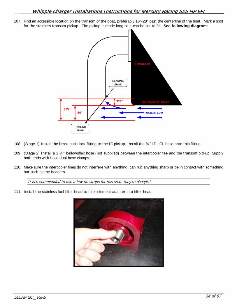
107. Find an accessible location on the transom of the boat, preferably 16”-28” past the centerline of the boat. Mark a spot for the stainless transom pickup. The pickup is made long so it can be cut to fit. See following diagram:
LEADING EDGE
TRAILING EDGE
TRANSOM
BOTTOM OF BOAT
.875".50"
.375"
WATER FLOW
108. (Stage 1) Install the brass push lock fitting to the IC pickup. Install the ¾” ID LOL hose onto this fitting. 109. (Stage 2) Install a 1 ¼” bellowsflex hose (not supplied) between the intercooler tee and the transom pickup. Supply
both ends with hose dual hose clamps. 110. Make sure the intercooler lines do not interfere with anything, can rub anything sharp or be in contact with something
hot such as the headers.
It is recommended to use a few tie straps for this step: they’re cheap!!! 111. Install the stainless fuel filter head to filter element adapter into filter head.
Whipple Charger Installations Instructions for Mercury Racing 525 HP EFI
525HP SC _V3R5 35 of 67
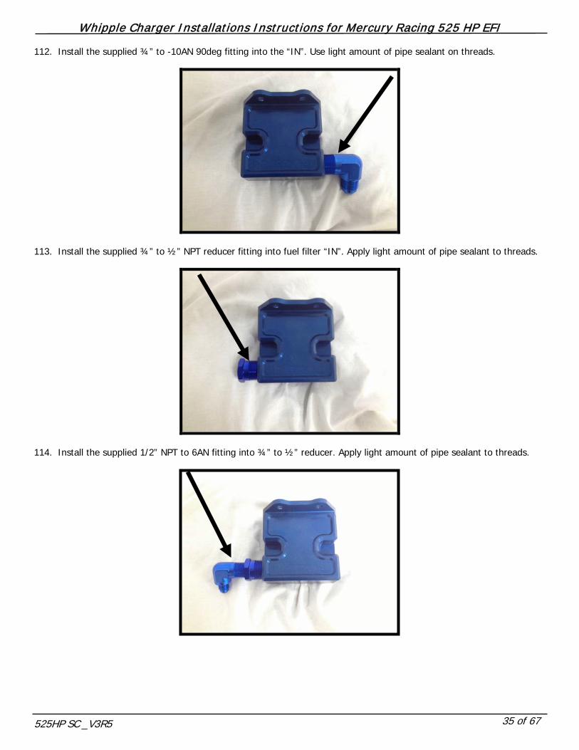
112. Install the supplied ¾” to -10AN 90deg fitting into the “IN”. Use light amount of pipe sealant on threads.
113. Install the supplied ¾” to ½” NPT reducer fitting into fuel filter “IN”. Apply light amount of pipe sealant to threads.
114. Install the supplied 1/2” NPT to 6AN fitting into ¾” to ½” reducer. Apply light amount of pipe sealant to threads.
Whipple Charger Installations Instructions for Mercury Racing 525 HP EFI
525HP SC _V3R5 36 of 67
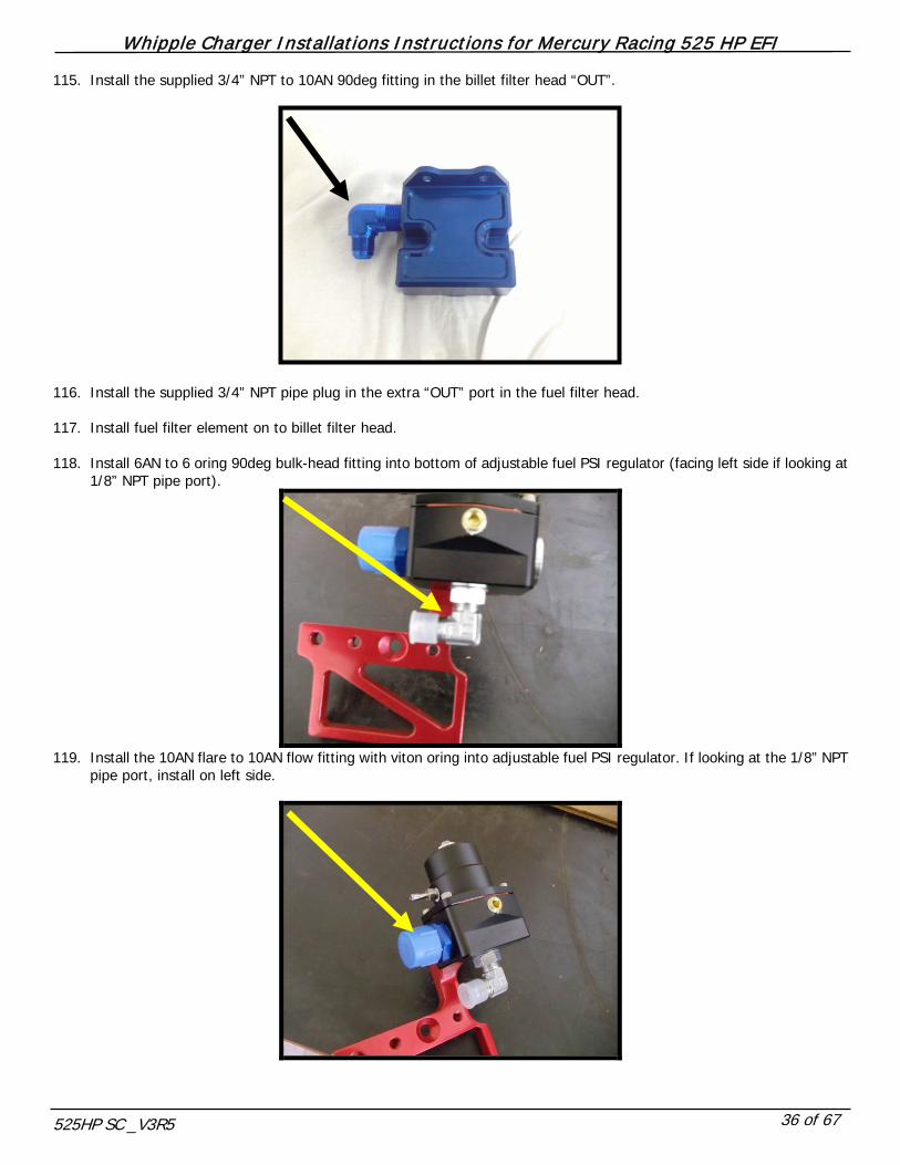
115. Install the supplied 3/4” NPT to 10AN 90deg fitting in the billet filter head “OUT”.
116. Install the supplied 3/4” NPT pipe plug in the extra “OUT” port in the fuel filter head. 117. Install fuel filter element on to billet filter head. 118. Install 6AN to 6 oring 90deg bulk-head fitting into bottom of adjustable fuel PSI regulator (facing left side if looking at
1/8” NPT pipe port).
119. Install the 10AN flare to 10AN flow fitting with viton oring into adjustable fuel PSI regulator. If looking at the 1/8” NPT
pipe port, install on left side.

Whipple Charger Installations Instructions for Mercury Racing 525 HP EFI
525HP SC _V3R5 37 of 67
120. Install 10AN plug into adjustable regulator extra inlet port. If looking at logo on regulator, install on right side.
121. Install supplied 1/8” barbed fitting for regulator vacuum/boost reference into regulator with light amount of thread
sealant.
122. Mount adjustable fuel pressure regulator to billet mount supplied. Secure with the (2) 10/32” x socket head allen bolts.
Whipple Charger Installations Instructions for Mercury Racing 525 HP EFI
525HP SC _V3R5 38 of 67
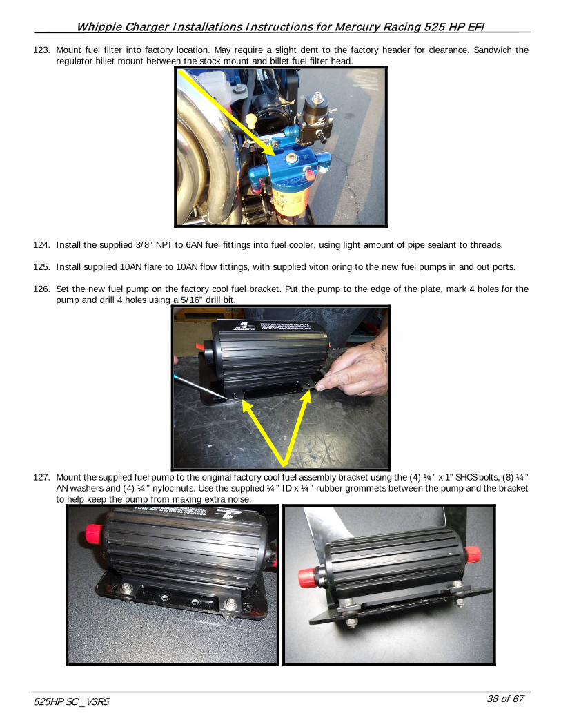
123. Mount fuel filter into factory location. May require a slight dent to the factory header for clearance. Sandwich the regulator billet mount between the stock mount and billet fuel filter head.
124. Install the supplied 3/8” NPT to 6AN fuel fittings into fuel cooler, using light amount of pipe sealant to threads. 125. Install supplied 10AN flare to 10AN flow fittings, with supplied viton oring to the new fuel pumps in and out ports. 126. Set the new fuel pump on the factory cool fuel bracket. Put the pump to the edge of the plate, mark 4 holes for the
pump and drill 4 holes using a 5/16” drill bit.
127. Mount the supplied fuel pump to the original factory cool fuel assembly bracket using the (4) ¼” x 1” SHCS bolts, (8) ¼”
AN washers and (4) ¼” nyloc nuts. Use the supplied ¼” ID x ¼” rubber grommets between the pump and the bracket to help keep the pump from making extra noise.
Whipple Charger Installations Instructions for Mercury Racing 525 HP EFI
525HP SC _V3R5 39 of 67
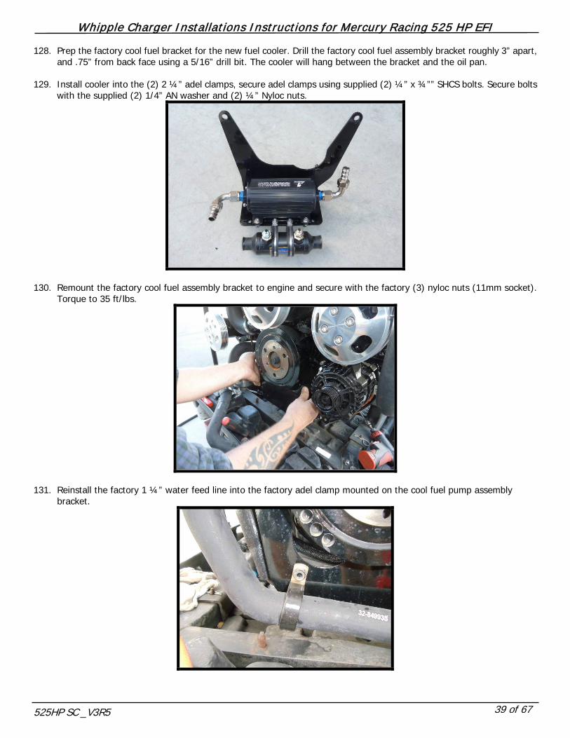
128. Prep the factory cool fuel bracket for the new fuel cooler. Drill the factory cool fuel assembly bracket roughly 3” apart, and .75” from back face using a 5/16” drill bit. The cooler will hang between the bracket and the oil pan.
129. Install cooler into the (2) 2 ¼” adel clamps, secure adel clamps using supplied (2) ¼” x ¾”” SHCS bolts. Secure bolts
with the supplied (2) 1/4” AN washer and (2) ¼” Nyloc nuts.
130. Remount the factory cool fuel assembly bracket to engine and secure with the factory (3) nyloc nuts (11mm socket).
Torque to 35 ft/lbs.
131. Reinstall the factory 1 ¼” water feed line into the factory adel clamp mounted on the cool fuel pump assembly bracket.

Whipple Charger Installations Instructions for Mercury Racing 525 HP EFI
525HP SC _V3R5 40 of 67
132. Install one of the supplied 1 ¼” 90deg rubber hoses to the port side of the fuel cooler. Secure with the supplied #20 hose clamp. Match the length to the factory feed line and cut to fit. Install the 1 ¼” stainless hose coupler and install both hoses onto hose barb. Secure both hoses with the supplied #20 hose clamps.

Whipple Charger Installations Instructions for Mercury Racing 525 HP EFI
525HP SC _V3R5 41 of 67
133. Install one of the supplied 1 ¼” 90deg rubber hoses to the starboard side of the fuel cooler. Secure with the supplied #20 hose clamp. Match the length to the factory outlet hose and cut the factory hose to fit.
134. WARNING!! Manufacture only high quality, high-pressure fuel lines!! You must have a minimum of
–10 (5/8” ID) hose to feed the fuel rail; anything smaller is unacceptable and will not feed the system with the proper amount of fuel flow.
Electric Fuel Pump
Inlet From Tank
Injector Fuel Rail
Fuel Pressure Regulator
Fuel PSI Test Port
Fuel Cooler
FUEL FILTER/WATER SEPERATOR
OUT IN
RETURN
Whipple Charger Installations Instructions for Mercury Racing 525 HP EFI
525HP SC _V3R5 42 of 67
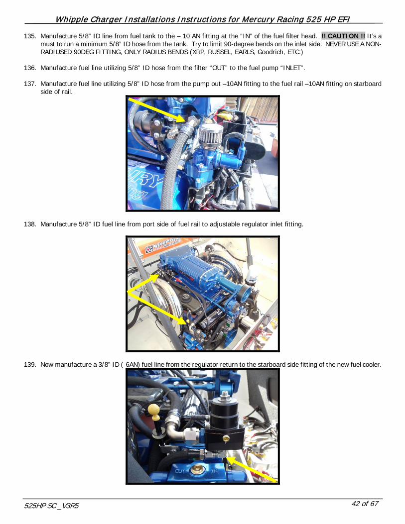
135. Manufacture 5/8” ID line from fuel tank to the – 10 AN fitting at the “IN” of the fuel filter head. !! CAUTION !! It’s a must to run a minimum 5/8” ID hose from the tank. Try to limit 90-degree bends on the inlet side. NEVER USE A NON-RADIUSED 90DEG FITTING, ONLY RADIUS BENDS (XRP, RUSSEL, EARLS, Goodrich, ETC.)
136. Manufacture fuel line utilizing 5/8” ID hose from the filter “OUT” to the fuel pump “INLET”. 137. Manufacture fuel line utilizing 5/8” ID hose from the pump out –10AN fitting to the fuel rail –10AN fitting on starboard
side of rail.
138. Manufacture 5/8” ID fuel line from port side of fuel rail to adjustable regulator inlet fitting.
139. Now manufacture a 3/8” ID (-6AN) fuel line from the regulator return to the starboard side fitting of the new fuel cooler.

Whipple Charger Installations Instructions for Mercury Racing 525 HP EFI
525HP SC _V3R5 43 of 67
140. Manufacture another 3/8” ID (-6AN) fuel line from the fuel cooler port side fitting to the –6AN fitting to the ¼” to 6AN fitting of the billet fuel filter head.
It is recommended to use a few tie straps for this step: they’re cheap!!!
141. Locate the 1/8” barbed fitting on the backside of the intake manifold. Install the supplied 1/8” vacuum line to the 1/8”
fitting to the adjustable regulator barbed fitting.
142. Route the supplied fuel pump relay harness from the IAC relocation bracket to the new supplied fuel pump. Install the
red positive wire eyelet to the + positive.
Whipple Charger Installations Instructions for Mercury Racing 525 HP EFI
525HP SC _V3R5 44 of 67
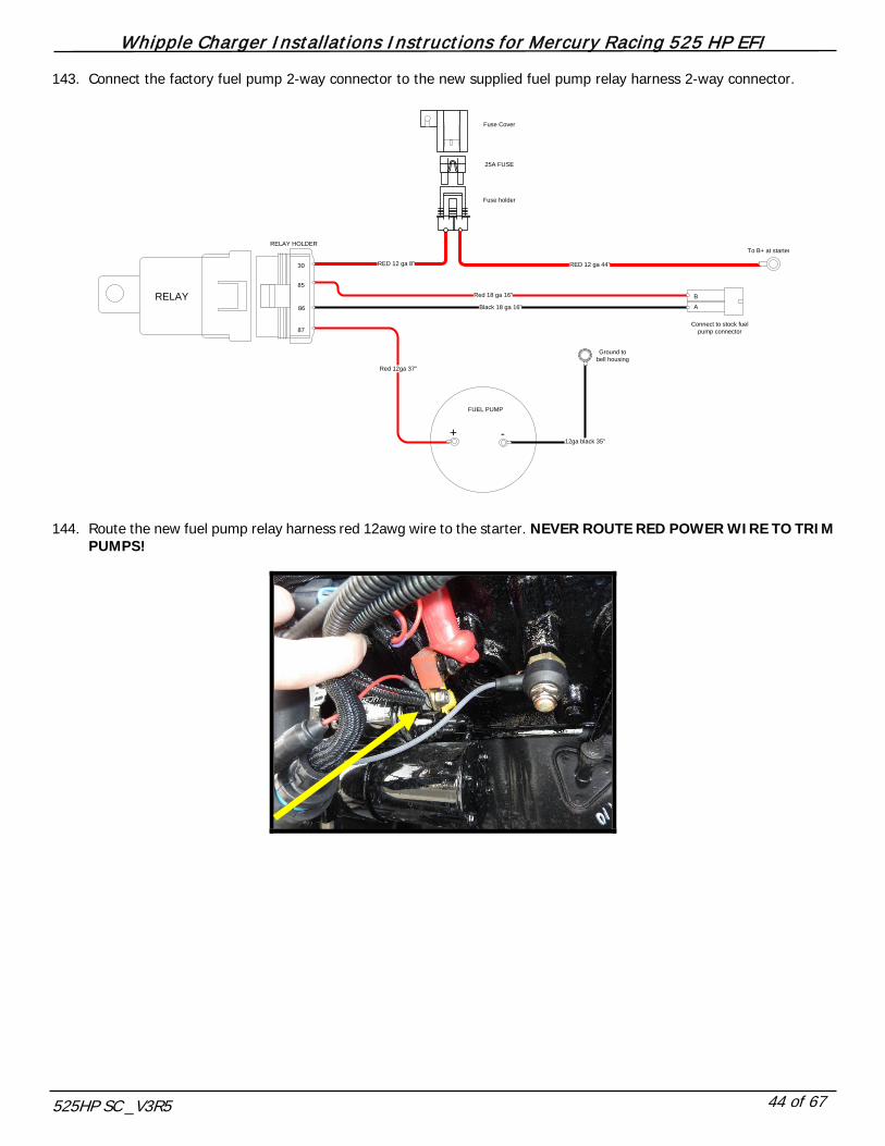
143. Connect the factory fuel pump 2-way connector to the new supplied fuel pump relay harness 2-way connector.
Red 18 ga 16"
RED 12 ga 8"
Black 18 ga 16"
Red 12ga 37"
RED 12 ga 44"
Fuse Cover
Fuse holder
25A FUSE
12ga black 35"
FUEL PUMP
RELAY HOLDER
87
86
85
30
RELAY B
A
+ -
Ground to bell housing
Connect to stock fuel pump connector
To B+ at starter
144. Route the new fuel pump relay harness red 12awg wire to the starter. NEVER ROUTE RED POWER WIRE TO TRIM
PUMPS!
Whipple Charger Installations Instructions for Mercury Racing 525 HP EFI
525HP SC _V3R5 45 of 67
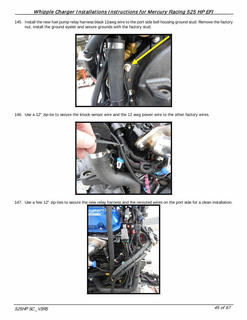
145. Install the new fuel pump relay harness black 12awg wire to the port side bell housing ground stud. Remove the factory nut, install the ground eyelet and secure grounds with the factory stud.
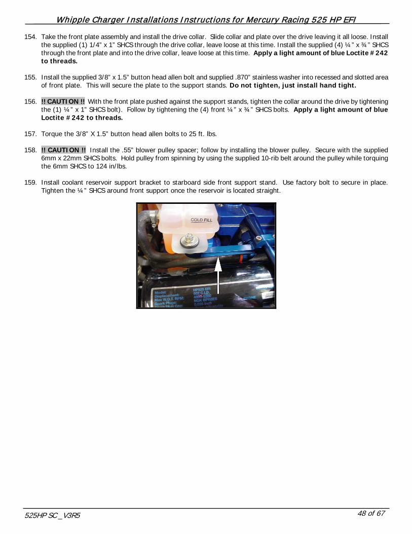
146. Use a 12” zip-tie to secure the knock sensor wire and the 12 awg power wire to the other factory wires.
147. Use a few 12” zip-ties to secure the new relay harness and the rerouted wires on the port side for a clean installation.

Whipple Charger Installations Instructions for Mercury Racing 525 HP EFI
525HP SC _V3R5 46 of 67
148. Install the supplied PCV valve in the factory grommet, located on the starboard side valve cover.
149. Locate the supplied 3/8” ID rubber hose and install the 90deg -6AN push lock fitting. Install this onto the supplied -6AN
fitting installed on the port side of the throttle body. Route hose behind the supercharger and to the starboard side PCV valve you previously installed.
150. Install supplied ¾” ID breather to factory rubber grommet on port side.

Whipple Charger Installations Instructions for Mercury Racing 525 HP EFI
525HP SC _V3R5 47 of 67
151. Install the supplied -8 AN hose to connect the IAC manifold to the starboard side 90deg -8AN fitting in the throttle body.
152. 2003 model year engines (serial numbers below 0M905000) must remote mount power steering reservoir as shown in
figure. Contact Whipple for this bracket, as this is not a standard part.
153. Install the (2) supplied 7.675” round support stands and install on the pre-installed studs in the front of the SC discharge
plate. The hex end will go against the SC/intercooler adapter plate. Tighten using the hex area on stand.
Whipple Charger Installations Instructions for Mercury Racing 525 HP EFI
525HP SC _V3R5 48 of 67
154. Take the front plate assembly and install the drive collar. Slide collar and plate over the drive leaving it all loose. Install the supplied (1) 1/4” x 1” SHCS through the drive collar, leave loose at this time. Install the supplied (4) ¼” x ¾” SHCS through the front plate and into the drive collar, leave loose at this time. Apply a light amount of blue Loctite #242 to threads.
155. Install the supplied 3/8” x 1.5” button head allen bolt and supplied .870” stainless washer into recessed and slotted area
of front plate. This will secure the plate to the support stands. Do not tighten, just install hand tight. 156. !! CAUTION !! With the front plate pushed against the support stands, tighten the collar around the drive by tightening
the (1) ¼” x 1” SHCS bolt). Follow by tightening the (4) front ¼” x ¾” SHCS bolts. Apply a light amount of blue Loctite #242 to threads.
157. Torque the 3/8” X 1.5” button head allen bolts to 25 ft. lbs. 158. !! CAUTION !! Install the .55” blower pulley spacer; follow by installing the blower pulley. Secure with the supplied
6mm x 22mm SHCS bolts. Hold pulley from spinning by using the supplied 10-rib belt around the pulley while torquing the 6mm SHCS to 124 in/lbs.
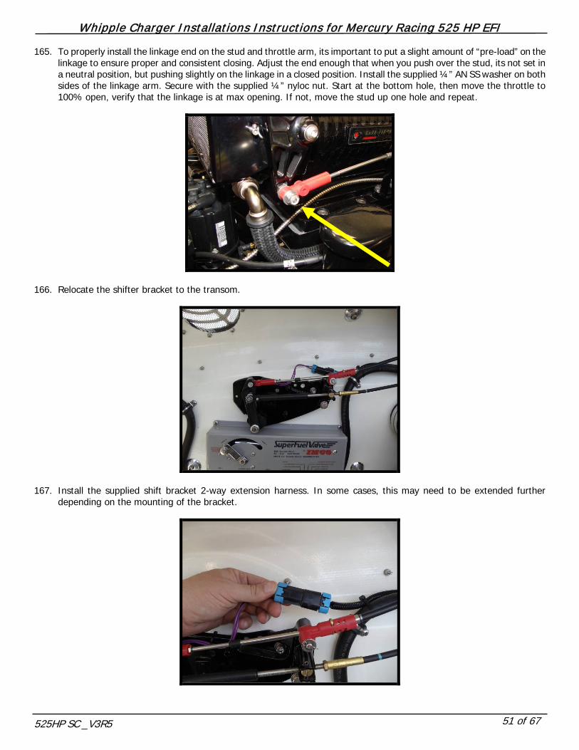
159. Install coolant reservoir support bracket to starboard side front support stand. Use factory bolt to secure in place.
Tighten the ¼” SHCS around front support once the reservoir is located straight.

Whipple Charger Installations Instructions for Mercury Racing 525 HP EFI
525HP SC _V3R5 49 of 67
160. WARNING!! Fill the new s/c compressor with oil per supplied instructions.
Make sure the SC is sitting square/flat.
Remove -4AN allen plug and fill SC with WHIPPLE SC OIL ONLY!!
Fill to the middle of the sight glass. NOTE: The W200AX compressor takes a maximum of 6.8 fl/oz (200mL).
Reinstall -4AN allen plug.
NOTE: After running the SC, the oil level will lower due to oil filling the bearings. The proper level should be between the bottom of the sight glass and the middle.
Change SC oil every 100 hours (every season) and only use WHIPPLE SC OIL!!
!! CAUTION !! Severe damage to the compressor will occur if you overfill the supercharger front gear case.
WHIPPLE SC OIL LEVEL
Fill to center of oil sight glass. 6.8 fl/ oz. or 200cc. DO NOT OVERFILL, WILL VOID WARRANTY!!
OIL FILL PLUG
MAXIMUM OIL LEVEL
MINIMUM OIL LEVEL
OIL LEVEL OPERATING RANGE
161. NOTE. Refill engine coolant system. Whipple recommends running a 50/50 mix of water/glycol. The entire system
has a capacity of 3.5 gallons. Refill half (1.75 gallons) of the coolant back with distilled water (ONLY). Reutilize the original coolant to fill the other 1.75 gallons.

Whipple Charger Installations Instructions for Mercury Racing 525 HP EFI
525HP SC _V3R5 50 of 67
162. Install the supplied ¼”-20 x 1 ½” stud into the throttle arms upper ¼” hole.
163. Install the supplied ¼”-20 x 1 ½” stud into the throttle anchor position.
164. Route the linkage to the front of the motor, starboard side. Test fit the factory linkage length to see what hole position
on the anchor, as there are 3 hole positions for multiple length configurations. Once you’ve figured a position, install anchor to ¼” stud by using a supplied ¼” AN washer on both sides of the linkage anchor and secure with supplied ¼” nyloc nut.
Whipple Charger Installations Instructions for Mercury Racing 525 HP EFI
525HP SC _V3R5 51 of 67
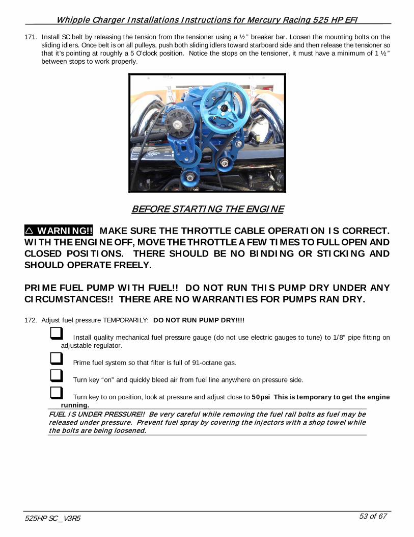
165. To properly install the linkage end on the stud and throttle arm, its important to put a slight amount of “pre-load” on the linkage to ensure proper and consistent closing. Adjust the end enough that when you push over the stud, its not set in a neutral position, but pushing slightly on the linkage in a closed position. Install the supplied ¼” AN SS washer on both sides of the linkage arm. Secure with the supplied ¼” nyloc nut. Start at the bottom hole, then move the throttle to 100% open, verify that the linkage is at max opening. If not, move the stud up one hole and repeat.
166. Relocate the shifter bracket to the transom.
167. Install the supplied shift bracket 2-way extension harness. In some cases, this may need to be extended further depending on the mounting of the bracket.

Whipple Charger Installations Instructions for Mercury Racing 525 HP EFI
525HP SC _V3R5 52 of 67
168. Adjust the TPS sensor to be in its proper range before starting the engine. With the key in the on position, probe the light blue/white wire with a volt meter. Slightly loosen the (2) SHCS bolts that hold the TPS adapter to throttle body. With your voltmeter, adjust until you find 4.45v-4.55v or with scan too, .45 to .55v. Once found, tighten billet adapter. Make sure that during tightening, it did not move. Turn the key back to the off position.
169. Pour in a mixture of engine coolant and distilled water, Whipple recommends running a mixture of 75% distilled water to
25% glycol. If you only drained the engine to the thermostat, then you may just top off the engine coolant reservoir with distilled water. A bottle of Redline Water Wetter is good to help reduce coolant temps.
170. Install the 91-octane decal on the dash, in a visible location.
Whipple Charger Installations Instructions for Mercury Racing 525 HP EFI
525HP SC _V3R5 53 of 67
171. Install SC belt by releasing the tension from the tensioner using a ½” breaker bar. Loosen the mounting bolts on the sliding idlers. Once belt is on all pulleys, push both sliding idlers toward starboard side and then release the tensioner so that it’s pointing at roughly a 5 O’clock position. Notice the stops on the tensioner, it must have a minimum of 1 ½” between stops to work properly.
BEFORE STARTING THE ENGINE WARNING!! MAKE SURE THE THROTTLE CABLE OPERATION IS CORRECT. WITH THE ENGINE OFF, MOVE THE THROTTLE A FEW TIMES TO FULL OPEN AND CLOSED POSITIONS. THERE SHOULD BE NO BINDING OR STICKING AND SHOULD OPERATE FREELY. PRIME FUEL PUMP WITH FUEL!! DO NOT RUN THIS PUMP DRY UNDER ANY CIRCUMSTANCES!! THERE ARE NO WARRANTIES FOR PUMPS RAN DRY. 172. Adjust fuel pressure TEMPORARILY: DO NOT RUN PUMP DRY!!!!
Install quality mechanical fuel pressure gauge (do not use electric gauges to tune) to 1/8” pipe fitting on adjustable regulator.
Prime fuel system so that filter is full of 91-octane gas.
Turn key “on” and quickly bleed air from fuel line anywhere on pressure side.
Turn key to on position, look at pressure and adjust close to 50psi This is temporary to get the engine running.
FUEL IS UNDER PRESSURE!! Be very careful while removing the fuel rail bolts as fuel may be released under pressure. Prevent fuel spray by covering the injectors w ith a shop towel while the bolts are being loosened.

Whipple Charger Installations Instructions for Mercury Racing 525 HP EFI
525HP SC _V3R5 54 of 67
173. WARNING!! Adjust fuel pressure, VERY IMPORTANT, MOTOR WILL NOT IDLE IF SET INCORRECTLY.
YOU MUST USE A HIGH QUALITY, HIGH ACCURACY MECHANICAL FUEL PRESSURE GAUGE ONLY!!!
With NO vacuum reference, adjust fuel pressure regulator by turning top allen screw on regulator (clockwise for more pressure, counter clockwise for less) until you reach 50 lbs. of fuel pressure. Tighten nut on regulator so allen does not vibrate out. DO NOT USE ELECTRIC FUEL PRESSURE GAUGES OR GAUGES THAT HAVE LARGE GAPS BETWEEN NUMBERS!!
Install 1/8” vacuum/boost line onto regulator-barbed fitting. Secure lines with zip ties. With motor running in vacuum, pressure should drop once line is connected and will rise above 50psi under boost. Under full boost, the fuel pressure must hold a steady 50psi of pressure (+/- 0-2psi). If not, there is a restriction in the line.
IDLE SPEED SETTING 174. Some motors may need an idle adjustment. First, you must understand the ECU has a desired idle speed that the motor
is always going to try to achieve. The desired idle speed is based off of engine coolant temp. See the chart below for the proper idle speed settings.
Temp F 50 66 82 97 113 129 145 160 176 Neutral 1000 950 900 850 800 750 750 750 750 In Gear 950 900 850 800 750 700 700 700 700
As shown in the image, you must adjust the socket head allen bolt to raise or lower the idle speed. Note that this is where the throttle stops in the relaxed or returned position.
Whipple Charger Installations Instructions for Mercury Racing 525 HP EFI
525HP SC _V3R5 55 of 67
PROBLEM: Engines that idle to high
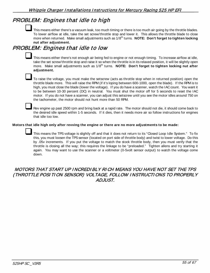
This means either there’s a vacuum leak, too much timing or there is too much air going by the throttle blades. To lower airflow at idle, take the set screw/throttle stop and lower it. This allows the throttle blade to close more when returned. Make small adjustments such as 1/8th turns. NOTE: Don’t forget to tighten locking nut after adjustment.
PROBLEM: Engines that idle to low
This means either there’s not enough air being fed to engine or not enough timing. To increase airflow at idle, take the set screw/throttle stop and raise it so when the throttle is in its relaxed position, it will be slightly open more. Make small adjustments such as 1/8th turns. NOTE: Don’t forget to tighten locking nut after adjustment.
To raise the voltage, you must make the setscrew (acts as throttle stop when in returned position) open the throttle blade more. This will raise the RPM (if it’s loping between 600-1000, open the blade). If the RPM is to high, you must close the blade (lower the voltage). If you do have a scanner, watch the IAC count. You want it to be between 10-30 percent (DC) in neutral. You must shut the motor off for 5 seconds to reset the IAC motor. If you do not have a scanner, you can adjust this setscrew until you see the motor idles around 750 on the tachometer, the motor should not hunt more than 50 RPM.
Rev engine up past 2500 rpm and bring back at a rapid rate. The motor should not die, it should come back to the desired idle speed within 1-5 seconds. If it dies, then it needs more air so follow instructions for engines that idle too low.
Motors that idle high only after revving the engine or there are no more adjustments to be made:
This means the TPS voltage is slightly off and that it does not return to its “Closed Loop Idle System.” To fix this, you must loosen the TPS sensor (located on port side of throttle body) and twist to lower voltage. Do this by .05v increments. If you put the voltage to match the stock throttle body, then you must verify that the throttle is closing all the way; this requires the linkage to be “preloaded.” Tighten allens and try starting it again. You may want to use the scanner or a voltmeter (0-5volt sensor output) to watch the voltage come down.
MOTORS THAT START UP INCREDIBLY RICH MEANS YOU HAVE NOT SET THE TPS
(THROTTLE POSITION SENSOR) VOLTAGE, FOLLOW INSTRUCTIONS TO PROPERLY ADJUST.

Whipple Charger Installations Instructions for Mercury Racing 525 HP EFI
525HP SC _V3R5 56 of 67
CRITICAL!!! LAKE TEST
POST-INSTALLATION CHECKLIST After installing the Whipple supercharger kit it is imperative that the following checklist be performed. Failure to perform
these simple tests may result in severe engine damage. 1. WARNING!! Make sure 91 octane or higher is in the vessel. If unsure, drain the tank completely empty and fill
with 91 or higher.
2. With the new 120 thermostat, under full throttle operation, near full speed, engine temp should not exceed 155 degrees
(ok to reach 175 during idle) and ideally should run between 120-140deg F. Side style pickups on drives are typically not
adequate for proper flow, a low water nose style pickup or external pickup may need to be installed to keep a high water
flow through the heat exchanger. If you have an XZ drive with dual water pickups, it is be necessary to plug side draft
holes to increase pressure.
3. WARNING!! Fuel pressure is the most critical parameter and must be checked during wide-open throttle operation.
Install a quality fuel pressure gauge to the extra port at the fuel PSI regulator (1/8” pipe). Attach the fuel pressure gauge
with a long enough hose so that it may be visible during operation. Under WOT, full boost, max rpm, the fuel pressure
should be 56 lbs (+/- 2lbs). This procedure takes two people – one to drive and the other to observe the gauge. Perform
the test in a safe area. If it does not maintain fuel pressure, you must find the restriction, as this results in a lean air to
fuel condition.
FUEL IS UNDER PRESSURE!! Be very careful while removing the fuel rail bolts as fuel may be released under pressure. Prevent fuel spray by covering the injectors w ith a shop towel while the bolts are being loosened.
MAINTENANCE AND SERVICE
It is recommended that the following items be checked at normal service intervals.
1. Check supercharger oil every 10-15 hours of operation.
2. Change supercharger oil every 50 hours or every season, which ever comes first.
3. Check the supercharger/accessory drive belt. Adjust or replace as required.
4. Inspect and clean fuel filter every 25 hours.
5. Clean idle air motor conical filter every 15 hours.
6. Inspect spark plugs every 25 hours.
7. Inspect and verify bypass actuator movement every 25 hours.
Whipple Charger Installations Instructions for Mercury Racing 525 HP EFI
525HP SC _V3R5 57 of 67
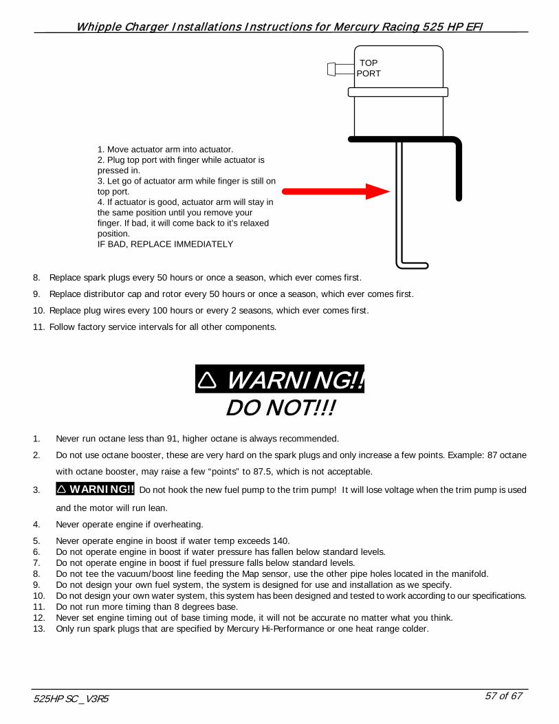
TOP PORT
1. Move actuator arm into actuator.2. Plug top port with finger while actuator is pressed in.3. Let go of actuator arm while finger is still on top port.4. If actuator is good, actuator arm will stay in the same position until you remove your finger. If bad, it will come back to it’s relaxed position. IF BAD, REPLACE IMMEDIATELY
8. Replace spark plugs every 50 hours or once a season, which ever comes first.
9. Replace distributor cap and rotor every 50 hours or once a season, which ever comes first.
10. Replace plug wires every 100 hours or every 2 seasons, which ever comes first.
11. Follow factory service intervals for all other components.
WARNING!! DO NOT!!!
1. Never run octane less than 91, higher octane is always recommended.
2. Do not use octane booster, these are very hard on the spark plugs and only increase a few points. Example: 87 octane
with octane booster, may raise a few “points” to 87.5, which is not acceptable.
3. WARNING!! Do not hook the new fuel pump to the trim pump! It will lose voltage when the trim pump is used
and the motor will run lean.
4. Never operate engine if overheating.
5. Never operate engine in boost if water temp exceeds 140. 6. Do not operate engine in boost if water pressure has fallen below standard levels. 7. Do not operate engine in boost if fuel pressure falls below standard levels. 8. Do not tee the vacuum/boost line feeding the Map sensor, use the other pipe holes located in the manifold. 9. Do not design your own fuel system, the system is designed for use and installation as we specify. 10. Do not design your own water system, this system has been designed and tested to work according to our specifications. 11. Do not run more timing than 8 degrees base. 12. Never set engine timing out of base timing mode, it will not be accurate no matter what you think. 13. Only run spark plugs that are specified by Mercury Hi-Performance or one heat range colder.
Whipple Charger Installations Instructions for Mercury Racing 525 HP EFI
525HP SC _V3R5 58 of 67
Whipple Charger Installations Instructions for Mercury Racing 525 HP EFI
525HP SC _V3R5 59 of 67
Whipple Charger Installations Instructions for Mercury Racing 525 HP EFI
525HP SC _V3R5 60 of 67
Whipple Charger Installations Instructions for Mercury Racing 525 HP EFI
525HP SC _V3R5 61 of 67

Whipple Charger Installations Instructions for Mercury Racing 525 HP EFI
525HP SC _V3R5 62 of 67
Whipple Charger Installations Instructions for Mercury Racing 525 HP EFI
525HP SC _V3R5 63 of 67

Whipple Charger Installations Instructions for Mercury Racing 525 HP EFI
525HP SC _V3R5 64 of 67
IMPORTANT INFORMATION
SPEEDS Due to the variance in boats and combinations, it’s impossible to guarantee the speed increases or stability of the boat with the increased power and larger propellers. You must use your discretion for proper boating safety. In most applications, you will need 4 pitches larger propellers to maintain proper rpm ranges when supercharged. BOOST LEVELS All Whipple kits are shipped with approximately 6-7psi for stock engines (@ sea level). Additional pulley’s are available for lower and higher boost levels, the supplied ECM has been calibrated for 4-10lbs of boost, sea level to 5000 feet elevation. With proper ECM calibration, the factory engine has proven to withstand 8psi before detonation on 91-octane fuel. Higher boost levels must run higher octane levels such as 100LL, 104, 110, 116, etc. Whipple does not recommend exceeding 10psi of boost on stock engines. MUFFLERS Many states are now mandating lower DB levels and some must use mufflers to reach those levels. There are many different systems out there, and we cannot test them all. It’s very important that you measure your boost level in the engine before and after the muffler s installed. If the mufflers are limiting flow, you will see an increase in boost. While the effective power may be the same, this can increase cylinder temperatures to critical levels and should be avoided. Whipple has tested Gibson muffler tips and have found these to be very effective at lowering the DB level while not limiting exhaust flow. Again, there are many different systems out there so some testing may be required. EXHAUST HEADERS The stock CMI sport tube headers are the best fit for these applications and are capable of making up to 1000HP. There is no reason to change these in anyway. FUEL SYSTEM The Whipple fuel system (FLOW) needs no additional changes for power levels up to 900HP. After 900HP, the supplied fuel pump will reach it’s maximum capacity and will need to be replaced to a larger size, consequently, to reach this power level, internal engine modifications will be required. Consult your authorized Whipple dealer for more information. AIR FUEL RATIO Air fuel ratio is the measurement of the amount of air and fuel being burned during the combustion process. In order for you to monitor the air fuel ratio, you must have a 18mm stainless steel bung welded into the collector of the header, within 2” of the sealing flange or in the tail pipe, approx. 2” away from the sealing flange. This must be double welded to insure that there are no water leaks. There are many companies that can do this for you, CMI, Teague Custom Marine, Imco, Eddie Marine, Stellings, etc. There are currently many different air fuel-monitoring systems and accuracy is not always guaranteed. Wide band oxygen sensors vary over time and deteriorate with uses of leaded gasoline. Whipple only uses Horiba wide band analyzers and UEGO 6-wire sensors, the most accurate available. Our sensors are checked after every use and transfer functions are changed every time so make sure you’re using an accurate meter. There are currently quite a few meters on the market that do the job pretty well, some good low cost a/f meter at www.aemelectronics.com, www.ngk.com, www.innovatemotorsports.com, www.fuelairspark.com, www.autometer.com. The Whipple supplied calibration has a conservative tune where WOT should be around 11.75-12:1. Idle A/F will vary depending on engine temp, but this should roughly be 13:1. Cruising, mid level rpms and throttle ranges should come to 13:1. As boost increases, the air fuel will get progressively richer. The 525HP EFI systems are setup to run 50psi of fuel pressure static, which will run 56psi @ WOT. Adjusting the static pressure will either richen or lean the entire curve, this should only be done with an accurate a/f meter. Whipple has found that 12.6:1 is approx. the best a/f for power but is very dangerous on pump gas. Be very careful, too lean of an air fuel ratio increase cylinder temps and increase the chance of detonation, which is detrimental to engine life. FUEL OCTANE Never run a fuel octane that is below 91octane, (RON+MON)/2. It is recommended, when available, to run 92-94 octane. Never mix mid level (below 91) with 91+, this is very dangerous and can cause severe engine damage. Do not attempt to
Whipple Charger Installations Instructions for Mercury Racing 525 HP EFI
525HP SC _V3R5 65 of 67
increase octane ratings with octane boosters, these are very hard on spark plugs and many brands do very little to the actual octane rating. For emergence situations, the best octane booster found to date is made by NOS, the “Off-road” formula has shown to increase the octane rating nearly 2.5 points when mixed at it’s most concentrated level. Again, this is very hard on spark plugs so constant use will require increased spark plug maintenance. ENGINE COOLANT Whipple recommends running a 75/25 mix of distilled water and coolant vs. the factory 100% glycol. We also recommend 1-2 bottles of Red Line Water Wetter coolant additive. This will reduce air bubble insulation, which increases overall engine temp. INTERCOOLER WATER FLOW The intercooler does not need water being run through it at all times. It’s main function is to remove the heat from the compression of air, therefore you should always have water flow when your in boost to help reduce the manifold air temperature. The intercooler can withstand 50psi and becomes more effective with more water flow, therefore it’s ideal to pump as much water through the intercooler as possible, giving you the coolest discharge temps. FUEL LEVEL Never operate at WOT when the vessel fuel levels are below a ¼ tank. Low fuel levels could cause the fuel pump to cavitate and you’ll have fuel flow spikes resulting in lean conditions and consequently detonation.

Whipple Charger Installations Instructions for Mercury Racing 525 HP EFI
525HP SC _V3R5 66 of 67
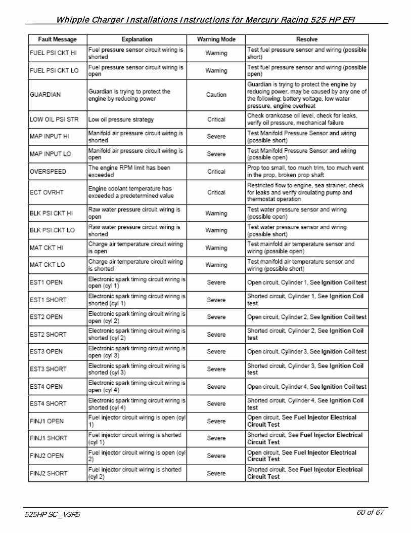
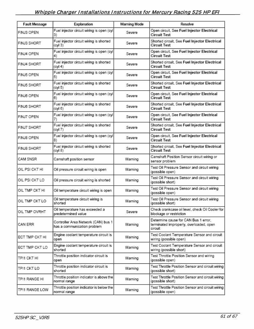
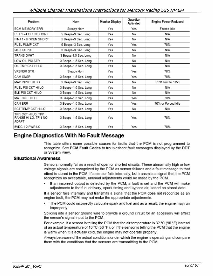
DIAGNOSTICS
FUEL PSI SENSOR
VOLTS 0.7 0.9 1.1 1.3 1.5 1.7 1.9 2.1 2.3 2.5 2.7 2.9 3.1 3.3 3.5 3.7 3.9 4.1 4.3 4.5 4.7 4.9
PSI 0 5 10 15 20 25 30 35 40 45 50 55 60 65 70 75 80 85 90 95 100 105
KPA 0 34 69 103 138 172 207 241 276 310 345 379 414 448 483 517 552 586 621 655 690 724
OIL PSI SENSOR
VOLTS 0.7 0.9 1.1 1.3 1.5 1.7 1.9 2.1 2.3 2.5 2.7 2.9 3.1 3.3 3.5 3.7 3.9 4.1 4.3 4.5 4.7 4.9
PSI 0 5 10 15 20 25 30 35 40 45 50 55 60 65 70 75 80 85 90 95 100 105
KPA 0 34 69 103 138 172 207 241 276 310 345 379 414 448 483 517 552 586 621 655 690 724
OIL TEMPERATURE SENSOR
DC VOLTS 0 0.3 0.6 0.9 1.3 1.5 1.9 2.1 2.5 2.8 3.1 3.4 3.8 4
DEG. C 200 143 113 96 84 75 64 59 52 45 40 32 25 16
DEG. F 392 289 235 205 183 167 147 138 126 113 104 90 77 61
OHMS 0 63.8 136 219.5 351 428 613 724 1000 1272 1631 2125 3166 4000
ENGINE COOLANT TEMPERATURE SENSOR
DC VOLTS 0 0.3 0.6 0.9 1.3 1.5 1.9 2.1 2.5 2.8 3.1 3.4 3.8 4
DEG. C 200 143 113 96 84 75 64 59 52 45 40 32 25 16
DEG. F 392 289 235 205 183 167 147 138 126 113 104 90 77 61
OHMS 0 63.8 136 219.5 351 428 613 724 1000 1272 1631 2125 3166 4000
2BAR MAP SENSOR
VOLTS 0.50 0.75 1.00 1.25 1.50 1.75 2.00 2.25 2.50 2.75 3.00 3.25 3.50 3.75 4.00 4.25 4.50
PSIa -14.7 -12.8 -11.0 -9.1 -7.2 -5.3 -3.5 -1.6 0.3 2.2 4.1 5.9 7.8 9.7 11.6 13.4 15.3
KPA 1 14 27 39 52 65 78 91 104 116 129 142 155 168 181 194 206
ENGINE GUARDIAN
The Whipple SC system utilizes the factory sensors as well as the new supplied system to maintain proper operation. The guardian system, when it detects a fault will limit the engine RPM by setting a code, setting the horn off and reducing the engine available power until the code is removed or goes away. If you get a code, connect a scan tool or diagnostic software to find out what parameter you’ve exceeded or what is out of range.
OIL PSI MINIMUM PSI
ENGINE RPM 400 1200 2000 2800 3600 4400 5200 6000
DC VOLTS 1.7 1.7 1.9 1.9 2.1 2.1 2.3 2.5
PSI 25 25 30 30 35 35 40 40
KPA 172 172 207 207 241 241 276 276
FUEL PRESSURE AT 0 BOOST 50PSI
ENGINE COOLANT TEMP 160 F
OIL TEMPERATURE 220 F

Whipple Charger Installations Instructions for Mercury Racing 525 HP EFI
525HP SC _V3R5 67 of 67
LIMITED WARRANTY
All merchandise manufactured by Whipple Industries is fully warranted against defects in workmanship and materials to the original purchaser of the Whipple Supercharger System. The limited warranty must be signed, dated and returned to Whipple Industries within 14 days of the purchase date accompanied by a copy of the original sales invoice. If an item is suspected of being defective, return it to Whipple Industries for inspection after obtaining the proper Return Authorization Number. If an item is determined to be defective, we will repair or replace it at our discretion within a period of one year from the shipping date on your invoice. Whipple Industries Inc. limited warranty specifially does not apply to products which have been (a) modified or altered in any way, (b) subjected to adverse conditions suach as misuse, neglect, accident, improper installation or adjustment, dirt, or other contaminants, water, corrosion or faulty repair; or (c) used in other than those specifically recommended by Whipple Industries Inc. All products designed for off-road use are considered racing parts and carry no warranty, either expressed or implied, as we have no control over how they are used. On warranty items, repair/replacements will be limited to parts manufactured by Whipple Industries and will not include claims for labor or inconvenience. All other merchandise distributed by Whipple Industries is warranted in accordance with the respective manufacturer's own terms of warranty. This warranty is expressly made in lieu of any and all other warranties expressed or implied, including the warranties of merchantability and fitness. Whipple Industries will not be responsible for any other expenses incurred by the customer under the terms of this warranty, nor shall it be responsible for any damages either consequential, special, contingent, expenses or injury arising directly or indirectly from the use of these products. Whipple Industries reserves the right to determine whether the terms of the warranty, set out above, have been properly complied with. In the event that the terms are not complied with, Whipple Industries shall be under no obligation to honor this warranty. By signing this form, you understand and agree to the terms above. NAME (Print) ADDRESS SIGNATURE CITY STATE ZIP DATE PHONE SC SERIAL # EMAIL VIN OR VESSEL #
(Found on compressor bearing plate) (Optional)