installation manual los1000 smart switch occupancy …
TRANSCRIPT

Installation ManualLOS1000 SMART SWITCH OCCUPANCY SENSOR
LightAlert !
1
Maximum Energy Savings: ■ Sensitive 180° view passive infrared
motion detector keeps lights on only when rooms are in use.
■ No ON switch so lights are never left on by mistake.
■ Meets new energy code standards. ■ Meets California Title 24. ■ Suitable for all utility rebate
programs.
Maximum Coverage: ■ 180° wide angle detection pattern. ■ Picks up people entering
doorways quickly with standard next to doorway location.
■ Covers 1000 square feet, eliminates need for multiple sensors.
■ Superb small movement sensitivity within 18 feet. Great for sedentary office use.
■ No dead spots with 18 sensing fingers.
Maximum Reliability: ■ “ZAP” (Zero Arc Point) Sensor
switches only at the zero arc point of an electrical cycle. Protects relay contacts from high inrush and kickback currects and lengthens ballast and sensor life.
Features:
Easy Installation: ■ Works with dimmers and
programmed rapid start electronic ballasts.
■ No minimum load requirement. ■ Replaces single pole wall switches
without additional wiring. ■ Fits decorator style, rectangular
opening switchplates. ■ Only 1/2” protrusion from switch
plate. ■ No adjustments required for most
installations. ■ Compact design fits standard switch
boxes with plenty of room for wiring. ■ LED Detection Indicator aids walk
testing and adjustments. ■ 30 second minimum delay time
speeds testing procedure. ■ Tamperproof control panel cover
reduces callbacks for tampering.
Maximum Versatility: ■ Switches most types of fluorescent
and/or incandescent lighting. Instant Start fluorescent ballasts may not be rated for use with any kind of occupancy sensor.
■ Fits single or multi-gang locations without special adapters.
■ Wide time delay choice adjust to active or sedentary movement.
■ Does not interfere with computers. ■ Superior RF immunity.
Specifications:
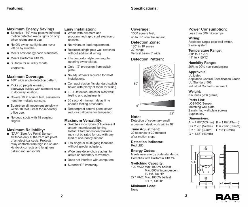
Coverage:1000 square feet,up to 35’ from the sensor.
Detection Zone:180° in 18 zones32’ rangeVertical beam 5” wide
Detection Pattern:
Note:Detection of sedentary small movement desk work within 18’Time Adjustment:30 seconds to 30 minutes after motion stops Detection Indicator:Red LED Energy Codes:Meets new energy code standards. Complies with California Title 24
Switching Capacity:120 VAC: Max 1000W ballast Max 800W incandescent 60 Hz, 1/8 HP277 VAC: Max 1800W ballast 60Hz, 1/8 HPMinimum Load:None
Power Consumption:Less than 500 microampsWiring:Replaces single pole wall switch, 2 wire system Temperature Range:-30° to + 122°F(-1° to + 50°C) Humidity Range:20% to 90% non-condensing
Approvals:UL ListedAppliance Control Specification GradeUL Standard 508Industrial Control Equipment
Weight:8 ounces (266 grams)Parts List:LOS1000 SensorMatching wall plate2 matching wall plate screwsBypass keyDimensions:A = 4.06”(103mm) B = 1.69”(43mm)C = 2.25” (57mm) D = 2.56” (65mm) E = 1.25” (32mm) F = 5”(13mm)G = 1.68” (43mm)
32’
4’
32’
50’
A D
BE
CGF
2 3

Selecting a Location
Locate the LightAlert LOS1000 where it has an unobstructed view of the room, particularly the areas normally occupied by people.Ideal mounting height is 3.5 to 4.5 feet above the floor.
If people can not see the sensor lens from their normal positions in the room, the sensor will not detect their presence.
High cabinets, walls, doors and other obstructions may limit the sensor’s view of the entire room. If obstructions can be moved the sensor will have a better view. If the areas obstructed are not areas normally occupied, the sensor will still be able to see normal occupancy.
If the room is L shaped or the sensor’s view is badly obstructed from the door switch location, use the LightAlert LOS2400 ceiling mounted sensor instead of the LOS1000.
Ceiling mounted LOS2400 sensor with 360° detection
Do not locate sensor over or looking at heating vents, baseboard heaters, hanging plants or air conditioners. Do not locate sensor where it will view direct sunlight.If the sensor’s location gives it a view of other rooms or hallways, lights will be turned on when movement is detected in these adjacent areas. If this is undesirable, the sensor’s detection zone may be restricted by covering a portion of the lens with a white paper label or tape.
Cabinet obstructs sensor’sview of active area
SensorObstruction moved,sensor has full view
Sensor
Sensor has view ofadjacent area
Sensor
1Caution:
■ TURN OFF ALL POWER BY REMOVING THE POWER FUSE OR TURNING OFF THE CIRCUIT BREAKER FOR YOUR SAFETY AND TO PREVENT DAMAGE TO THE UNIT.
■ Please read this entire Owner’s Manual before proceeding.
■ All wiring should comply with local electrical codes and may require a qualified electrician.
■ Make sure the total lighting load connected to the LightAlert LOS1000 does not exceed the following:120 VAC: Max 1000W ballast Max 800W incandescent277 VAC: Max1800W ballast
Exceeding the wattage limits may damage the unit. To switch more wattage, an electrician can install a relay to handle the load.
■ Do not use LightAlert LOS1000 to control high intensity discharge lights, fans, heaters or motors. Small bathroom exhaust fans may be used with LOS 1000.
■ The LOS 1000 may be used with both standard and program rapid start electronic fluorescent ballasts.
■ When the LOS1000 is initially installed and the main power circuit is restored, it will take 3 min before the LOS1000 will automatically switch the light off when no one is present. It takes 3 min for all circuits, including timer and memory to stabilize.
Installation
Installation Step by Step:1. Remove the existing switch, if
necessary. 2. Connect green ground lead from
LOS1000 to system ground. 3. Connect hot incoming power line to
black sensor wire. Connect lighting load to the red sensor wire.
4. Twist on wire nuts. Secure with electrical tape. Mount LOS1000 in wall box with two screws provided.
5. Place switch in OFF position before turning on power.
6. Press the Auto/Off switch IN to “Auto”. After a short delay, the lights will turn ON. When the room is vacted, the lights will turn OFF after the time delay you set.
7. See “Adjustments” section for control options. Only make adjustments after a 3 minute warmup period.
8. Attach the wall plate.
WALL MOUNTING BOX
ADJUSTMENT ACCESS COVER(Removable onlywhen switch plateis o )
Black
Red
White
Black
2
4 5
Wire Diagrams
Caution: ■TURN OFF ALL POWER BY REMOVING THE POWER FUSES OR TURNING OFF THE CIRCUIT BREAKER FOR YOUR SAFETY AND TO PREVENT DAMAGE TO THE UNIT. ■The ground wire must be tightly secured to ground.
3-Way Switch Wiring Diagram
Basic Wiring Diagram Single Level Lighting
Multiple Level Lighting Wiring Diagram
3-way Switch wiring Diagram
BLACK
BLACKRED
RED
BLACK
BLACK/HOT
WHITE/COMMONLOAD
GREEN
Basic Wiring DiagramSingle Level Lighting
COMMON (WHITE)
HOT (BLACK) REDLOAD
Multiple Level Lighting Wiring Diagram
RED
COMMON (WHITE)
HOT (BLACK)LOAD
LO AD
LO AD
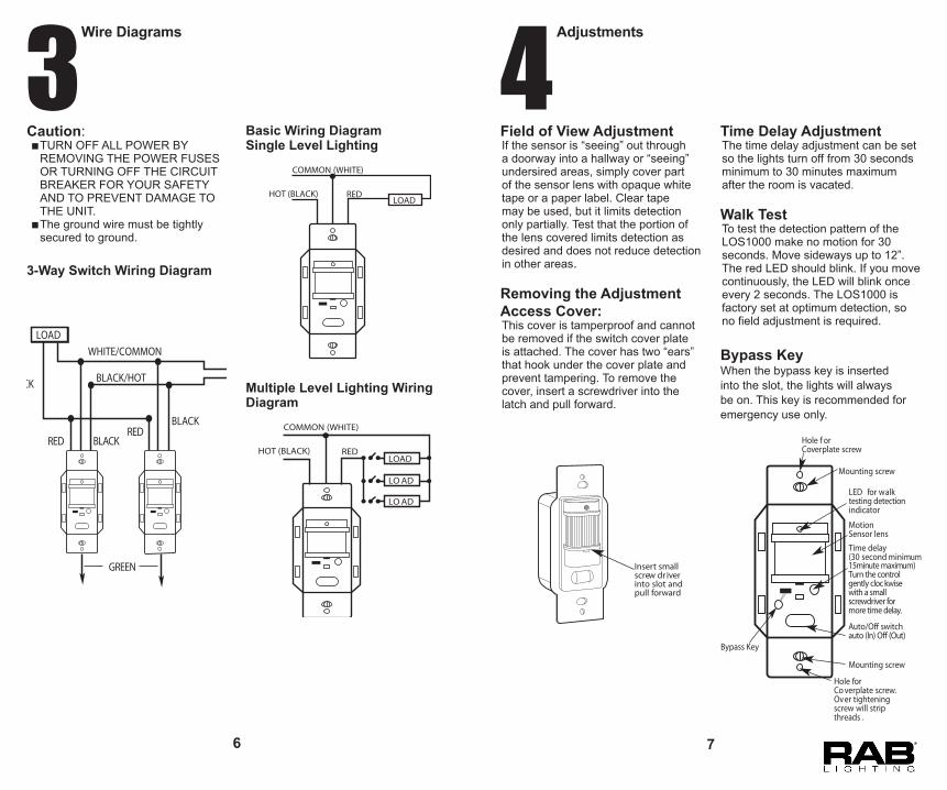
3Time Delay AdjustmentThe time delay adjustment can be set so the lights turn off from 30 seconds minimum to 30 minutes maximum after the room is vacated.
Walk TestTo test the detection pattern of the LOS1000 make no motion for 30 seconds. Move sideways up to 12”. The red LED should blink. If you move continuously, the LED will blink once every 2 seconds. The LOS1000 is factory set at optimum detection, so no field adjustment is required.
Bypass KeyWhen the bypass key is inserted into the slot, the lights will always be on. This key is recommended for emergency use only.
Field of View AdjustmentIf the sensor is “seeing” out through a doorway into a hallway or “seeing” undersired areas, simply cover part of the sensor lens with opaque white tape or a paper label. Clear tape may be used, but it limits detection only partially. Test that the portion of the lens covered limits detection as desired and does not reduce detection in other areas.
Removing the AdjustmentAccess Cover:This cover is tamperproof and cannot be removed if the switch cover plate is attached. The cover has two “ears” that hook under the cover plate and prevent tampering. To remove the cover, insert a screwdriver into the latch and pull forward.
Insert smallscrew dr iver into slot and pull forward
Hole f orCoverplate screw
Mounting screw
Mounting screw
LED for walktesting detectionindicator
Motion Sensor lens
Auto/O� switchauto (In) O� (Out)
Time delay(30 second minimum15minute maximum)Turn the controlgently cloc kwisewith a smallscrewdriver formore time delay.
Hole forCo verplate screw.Over tighteningscrew will stripthreads .
Bypass Key
4 Adjustments
6 7

Trouble Shooting
Lights Do Not Turn On1. Check that:
■ The lamps and fixtures work ■ wiring exactly matches the wiring diagram; ■ wiring polarity is correct; ■ power is on; ■ sensor has warmed up for 3 minutes; ■ off/auto switch is not OFF
2. Make sure that sensor is not “looking” at direct sunlight or an extremely bright light.
3. Make sure sensor’s view of the room is not blocked.
Lights Do Not Turn Off1. Check that the Time delay control is
set to minimum. 2. Stay completely out of the protection
pattern to avoid activation. Make sure sensor is not seeing movement in an adjacent area through a doorway or other opening.
3. Make sure unit is not aimed at something that would move or cause a temperature change such as plants, hot water pipes, air conditioners or heating vents.
4. Check that the wattage controlled does not exceed the maximum limits.
Lights Go On and Off Quickly1. Make sure lights are not shining
directly into the sensor.Check for white or reflective surfaces in the protection pattern.
2. Reduce sensor sensitivity by masking the lens with tape in the direction of the light or reflection (see section number 4 on Field of View Adjustment).
3. Check the wattage controlled does not exceed maximum limits.
4. Certain energy saving fluorescent lamps strobe when turned on within a minute of being turned off.
5. Make sure sensor can not “see” a light that it is controlling.
Lights Go On for “No Reason”1. Look for sources of electrical noise
such as fans or air conditioners on the same circuit or nearby. If possible unplug or move the noise sources.
2. Check if sensor is “seeing” into adjacent rooms or hallways. Mask sensor lens in that direction with opaque tape.
3. Check if sensor is “seeing” heaters or air conditioning vents. Mask sensor lens if necessary.
4. Make sure unit is at room temperature. If it was installed immediately after being in an extremely hot or cold environment, wait an hour for it to adjust.
5A LightAlert LOS1000 Smart Switch requires no maintenance other than keeping the lens area clean and free of obstructions. Do not attempt to open or repair the unit. There are dangerous voltages inside the case and no user serviceable parts.
Your LightAlert LOS1000 will be replaced or repaired, at our option, if it proves to be defective in workmanship or materials within one year from the date of original purchase.
For repair or replacement, return the product freight prepaid and insured to the address below. The LOS1000 should be packed carefully. Please include your sales receipt and a description of the problem.
If your unit is out of warranty or the damage is unrelated to its original manufacture, return your unit directly to RAB with check for $25.00 (payable to RAB Electric). We will repair or replace the unit.
Under no circumstances shall we be liable for any incidental or consequential damages arising out of or in connection with the use or performance of this product or other indirect damages with respect to loss of properly or revenue or cost of installation removal or re-installation. This warranty gives you specific legal rights and you may also have other rights which vary from state to state.
Limited Warranty
LightAlert®RAB Lighting, Inc.170 Ludlow AvenueNorthvale, New Jersey 07647-0970Tel: 888-722-1000Fax: 888-722-1232Website:www.rabweb.comEmail:[email protected]
8 9