installation instructions - eatonpub/@norway/... · 3 subject to technical alterations! ga-s015e...
TRANSCRIPT

1414
710d
1 Subject to technical alterations! GA-S015e
Installation Instructions
Cabinets KVS1 - 2 B10 for Construction Kits
Jean Müller GmbHElektrotechnische FabrikH.J.-Müller-Straße 765343 Eltville
Telefon: +49 6123 604-0Fax: +49 6123 [email protected]
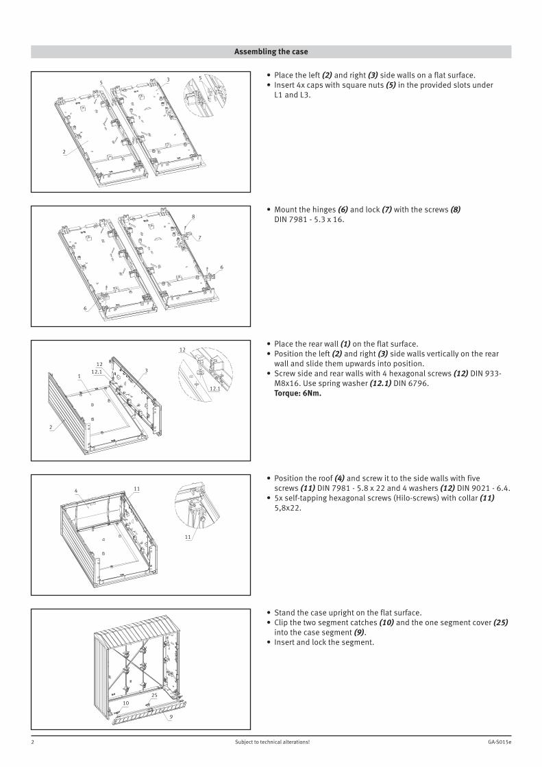
Assembling the case
2 Subject to technical alterations! GA-S015e
• Placetheleft(2) and right (3) side walls on a flat surface.• Insert4xcapswithsquarenuts(5)intheprovidedslotsunder L1 and L3.
• Mountthehinges(6) and lock (7) with the screws (8) DIN7981-5.3x16.
• Placetherearwall(1) on the flat surface.• Positiontheleft(2) and right (3) side walls vertically on the rear wallandslidethemupwardsintoposition.• Screwsideandrearwallswith4hexagonalscrews(12)DIN933- M8x16.Usespringwasher(12.1)DIN6796. Torque: 6Nm.
• Positiontheroof(4) and screw it to the side walls with five screws (11)DIN7981-5.8x22and4washers(12)DIN9021-6.4.• 5xself-tappinghexagonalscrews(Hilo-screws)withcollar(11) 5,8x22.
• Standthecaseuprightontheflatsurface.• Clipthetwosegmentcatches(10) and the one segment cover (25) into the case segment (9).• Insertandlockthesegment.
35
2
5
6
6
7
8
31
2
1212.1
12
12.1
4
11
11
9
1025

3 Subject to technical alterations! GA-S015e
• Placetherightdoor(13) on the flat surface.• Installtheblankingplate(14) in the front side of the door.
• Assemblingthelock Positionthedoorwiththeinnersideontop. Openthebagoflockparts(15). Slide the flat gasket (15.1)ontothethreadedsquareshaft. Insertthehandleunit(15) in the door from below. Slide the O-ring (15.2)ontothesquaresection. Fit the cover (15.3) and secure it with four screws (15.4). Screw the hexagon nut (15.5)ontothethreadedsquareshaftand tightenitwitha27mmspanner.
• Removethehexagonnut(15.6) and washer (15.7). Fitthesquarewasher(16). Inserttheupper(17) and lower (18) locking slides. Insertthelockingtongue(19)fromthetopandsecureitwiththe nut (15.6) and washer (15.7).• Donottightenthenuttoomuch:thelockingmechanismmuststill move easily.
• Insertthehingepins(20) and mount the catch (7) with screw (8) DIN7981-5.3x16.
Assembling the left and right doors
• Placetheleftdoor(22)ontheflatsurfacewithitsinnersideontop.• Insertthehingepins(20) and mount the catch (7) with screw (8) DIN7981-5.3x16.• Mounttheupperandlowerstopstrips(23) with four screws (24) S3.5 x 16.
14
13
13
15.4 15.5
15.115.2
15.3
15
15.615.7
18 16 1917
2087

4 Subject to technical alterations! GA-S015e
Final assembly
• Placetheleftdoor(B.1)inpositionandsecureitwiththehinge pins(20).• Placetherightdoor(B)inpositionandsecureitwiththehinge pins(20).• Insertthecylinderinthehandleunit(15) and secure it with screw (15.8).• Sticktheratingplate(21) to the inside of the door, close the door and lock it with the handle.• Ifnecessaryformountingthebusbarsormountingplates,insert theenclosedsquarenuts-M8(26)intheprovidedslots.
Parts list, construction kits KVS1-10 - Article No.S711002210 and KVS2-10 - Article No.S721001710
Position Designation Quantity Artikel No.KVS1-10
Artikel No.KVS2-10
1 Rearwall 1x S8100856 S8200864
2 Side wall, left 1x S8900872 S8900872
3 Side wall, right 1x S8900873 S8900873
4 Roof 1x S8100859 S8200867
5 Covercapwithsquarenut 4x S8900209 S8900209
6 Hinge 2x S8900527 S8900527
7 Catch 4x S8900592 S8900592
8 ScrewDIN7981-5,3x16 6x Y3000061 Y3000061
9 Segment 1x S8100858 S8200866
10 Segment lock 2x S8900524 S8200866
11 Self-tappinghexagonalscrews(Hilo-screws)withcollars5,8x22 5x Y3000162 Y3000162
12 HexagonalscrewsDIN933-M8x16 4x Y3000170 Y3000170
12.1 WashersDIN6796-8 4x Y3000117 Y3000117
13 Door right 1x S8100860 S8200868
14 Blankingplate 1x S8901158 S8901158
15 Handle unit 1x S8900346 S8900346
16 Washer 1x S8900197 S8900197
17 Lockingslide,top 1x S8900515 S8900515
18 Locking slide, bottom 1x S8900516 S8900516
19 Locking tongue 1x S8900591 S8900591
20 Hingepin 4x S8900426 S8900426
21 Ratingplate 1x S8901082 S8901082
22 Door, left 1x S8100857 S8200865
23 Stopstrip 2x S8100707 S8100707
24 Screw S3,5x16 4x Y3000096 Y3000096
25 Segment cover 1x S8901217 S8901217
26 ThinsquarenutsDIN562-M8 8x Y3000073 Y3000073
Edition04/08
20
2026
21
15
15.8
5 Subject to technical alterations! GA-S015e
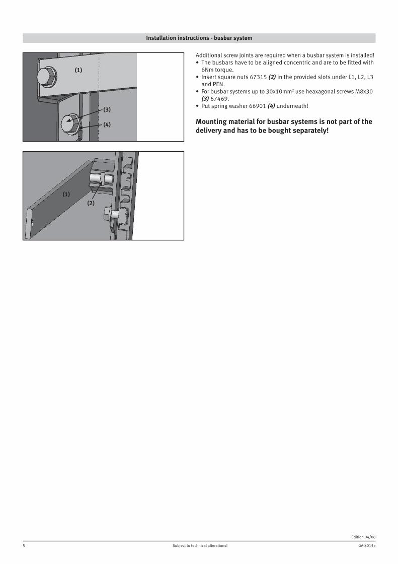
Installation instructions - busbar system
Edition04/08
Additionalscrewjointsarerequiredwhenabusbarsystemisinstalled!• Thebusbarshavetobealignedconcentricandaretobefittedwith 6Nmtorque.• Insertsquarenuts67315(2)intheprovidedslotsunderL1,L2,L3 andPEN.• Forbusbarsystemsupto30x10mm2useheaxagonalscrewsM8x30 (3) 67469.• Putspringwasher66901(4) underneath!
Mounting material for busbar systems is not part of the delivery and has to be bought separately!
(1)
(4)
(3)
(1)(2)

