installation guide guide contents 1 introduction 2 uts interfaces s erial interface.....2-1 uts,...
TRANSCRIPT
CoBox
Universal Thin Server
Installation Guide
Contents
1 INTRODUCTION
2 UTS INTERFACES
SERIAL INTERFACE ...................................................................................... 2-1UTS, Ethernet and Token Ring: ........................................................... 2-1
NETWORK INTERFACE.................................................................................. 2-1HARDWARE ADDRESS .................................................................................. 2-1
Network Hardware Address................................................................. 2-1UTS Ethernet ...................................................................................... 2-2UTS Token Ring ................................................................................ 2-2
POWER SUPPLY............................................................................................ 2-2
3 NETWORK PROTOCOLS
PACKING ALGORITHM.................................................................................. 3-1CHANNEL IDENTIFICATION........................................................................... 3-1IP ADDRESS ................................................................................................ 3-1PORT NUMBER............................................................................................. 3-1
4 CONFIGURATION
NETWORK CONFIGURATION ......................................................................... 4-1FACTORY IP ADDRESS ................................................................................. 4-1INITIAL IP ADDRESS SETTING ...................................................................... 4-1SERIAL CONFIGURATION.............................................................................. 4-2CONFIGURATION PARAMETERS .................................................................... 4-3BASIC PARAMETERS .................................................................................... 4-3
Ethernet Interface ................................................................................ 4-3IP Address........................................................................................... 4-3Gateway IP Address ............................................................................ 4-3Netmask.............................................................................................. 4-3Telnet Config Password....................................................................... 4-3
CHANNEL SPECIFIC PARAMETERS................................................................. 4-4Interface Mode .................................................................................... 4-4Flow Control ....................................................................................... 4-5Port Number........................................................................................ 4-5Remote IP Address.............................................................................. 4-5Remote TCP Port ................................................................................ 4-5Connect Mode ..................................................................................... 4-6Automatic Connection Address............................................................ 4-6Disconnect Mode................................................................................. 4-7

Force Telnet Mode .............................................................................. 4-7Buffer Flushing ................................................................................... 4-7Inactivity Timeout ............................................................................... 4-8Pack Control ....................................................................................... 4-8Send Characters................................................................................... 4-8Telnet Terminal Type .......................................................................... 4-9Exit Configuration Mode ..................................................................... 4-9
5 MONITOR MODE AND FIRMWARE UPGRADE
MONITOR COMMANDS ................................................................................. 5-1FIRMWARE DOWNLOAD SERIAL ................................................................... 5-2DISTRIBUTE FIRMWARE ............................................................................... 5-2FIRMWARE DOWNLOAD FROM HOST ............................................................ 5-2
6 SERIAL LINE INTERFACES
CONNECTOR PINOUT RS-232C, CHANNE1 1 ................................................. 6-1CONNECTOR PINOUT RS-232C CHANNEL 2 .................................................. 6-1CONNECTOR PINOUT RS-422/485 ................................................................ 6-2LINE INTERFACE DESCRIPTION ..................................................................... 6-2
First Channel, RS-232C....................................................................... 6-2Secondary RS-232C Interface .............................................................. 6-2RS-422/485 Interface........................................................................... 6-3
7 APPLICATION EXAMPLES
ASCII TERMINAL TO HOST FOR LOGIN......................................................... 7-1RS-485 2-WIRE PROLONGATION OVER NETWORK......................................... 7-1TELNET SERVER FOR DEVICE MANAGEMENT ................................................ 7-2PRINTER CONNECTION ................................................................................. 7-2
Software Handshake............................................................................ 7-3Printer Ready Signal............................................................................ 7-3
8 LED STATUS DISPLAY
YELLOW AND GREEN LED........................................................................... 8-1RED LED .................................................................................................... 8-1
9 TECHNICAL DATA
CPU, MEMORY CONTROLLERS: ................................................................... 9-1SERIAL INTERFACE ...................................................................................... 9-1NETWORK INTERFACE.................................................................................. 9-1POWER SUPPLY............................................................................................ 9-1POWER CONSUMPTION ................................................................................. 9-1LEDS .......................................................................................................... 9-1CASE........................................................................................................... 9-1DIMENSIONS................................................................................................ 9-1

WEIGHT ...................................................................................................... 9-1
A TOKEN RING SPECIFIC
B IP ADDRESSES, NETMASK ETC
C BINARY TO HEX CONVERSION
WARRANTY AND DECLARATIONS

Introduction
1-1
1 IntroductionThe CoBox Universal Thin Server (UTS) is designed to connect peripheralswith a serial interface to an Ethernet or Token Ring network using the TCP/IPprotocol family (TCP for transparent stream- and UDP for datagramapplications). Various peripherals can be interfaced, for example:
• terminals• time/attendance and data collection devices• CNC controllers• industrial robots• data display units• instruments• printers• modems
Depending on the model used, UTS’s have different network interfaces toconnect peripherals.
The UTS connects peripherals through a transparent TCP data channel or aTelnet connection to computers or another UTS. Datagrams (protocol blocks)can be sent by UDP. The network interface speed is 10-Mbit for Ethernetmodels and 4- or 16-Mbit for Token Ring versions.

UTS Interfaces
2-1
2 UTS InterfacesDepending on the model, the UTS supports different peripheral device interfaceconnections with different network topologies:
2.1 Serial Interface
2.1.1 UTS, Ethernet and Token Ring:1 x RS-232/RS-422 DB25 female (channel 1), software selectable, includingRS-485 2 and 4-wire support, up to 115kBaud. 1 x RS 232 interface DB9 male(channel 2), up to 115k Baud.
Figure 2-1
2.2 Network InterfaceEthernet models support 10Mbit; Token Ring models support 4 and 16Mbitnetwork speed, switch or jumper selectable. Token Ring Source Bridge routingand administered address is fully supported.
2.3 Hardware Address
2.3.1 Network Hardware AddressThe hardware address of the UTS can be calculated from the serial number andtype:
First three bytes are fixed, and read 00-20-4AFourth byte is the type of the unit:
• 02 for UTS Ethernet• 08 for all Token Ring models
Fifth and sixth bytes are the serial number in hex notation.

UTS Interfaces
2-2
Depending on the model, UTS supports different physical network interfaces.The following list gives model-specific information:
2.3.2 UTS Ethernet10BaseT (RJ-45 Connector) andAUI (SubD15 Connector) for external transceiver connections.
Figure 2-2
2.3.3 UTS Token RingSTP and UTP interfaces (SubD9 and RJ-45)Ring speed (4/16Mbit) switch selectable from outside of UTS.
Figure 2-3
2.4 Power SupplyDepending on the model, the UTS has different power supply needs. In Europe(230VAC) and USA (110VAC), the UTS external models are shipped with anAC power adapter. Power consumption varies with connected transceivers,phantom current, etc. Typically, the Ethernet version consumes around 250mAwith the 10BaseT interface activated, while the Token Ring version needsapproximately 400mA at 15V (including the phantom drive).
Network Protocols
3-1
3 Network ProtocolsThe UTS family uses TCP/IP protocols for network communication. Thesupported standards are: ARP, UDP, TCP, ICMP, Telnet, TFTP and SNMP.For transparent connections, TCP/IP (binary stream) or Telnet protocols areused. Firmware updates can be done with the TFTP protocol.
The IP protocol defines addressing, routing and data block handling over thenetwork. The TCP (transmission control protocol) assures that no data is lost orduplicated, and that everything sent into the connection on one side arrives atthe target exactly as it was sent.
For typical datagram applications where devices interact with others withoutmaintaining a point to point connection, UDP is used (customer specificversions and “Datagram” mode).
3.1 Packing AlgorithmThe two available packet algorithms (which define how and when packets aresent to the network) are software selectable on a per-channel base. The standardalgorithm is optimized for applications where UTS is used in a localenvironment, allowing for very small delays for single characters while tryingto keep the packet count low. The alternate packing algorithm minimizes thepacket count on the network, and is especially useful for applications in routedWide Area Networks. Various parameters can be set in this mode to economizethe serial data stream.
3.2 Channel IdentificationThe UTS has one IP Address. The port number selects the specific channel,which must be unique.
3.3 IP AddressEvery device connected to the TCP/IP network must have a unique IP address.This IP address is used to reference the specific device, for example to build aconnection to a serial port. See Appendix B for a complete description of IPAddressing.
3.4 Port NumberEvery TCP connection and every UDP datagram is defined by the two peer IPaddresses, which are source and destination port number. These port numbersare necessary to address different applications or channels on a network host.The port number can be compared to an extension on a PBX system.

Network Protocols
3-2
A Telnet application (login to a host with an ASCII terminal) is commonlyassigned TCP port number 23. More than one Telnet connection can beestablished to one host to the Telnet port; however, the other peer IPaddress/port number combination must be different.
In the UTS, a different port number for each channel must be configured. TheUTS uses this port number as the source port in outgoing messages and receivesconnections or UDP datagrams, which are addressed to this number. Port 9999(decimal) is used for remote configuration.

Configuration
4-1
4 ConfigurationThe UTS can be configured by various remote or local methods. Either use anASCII terminal or terminal emulation to locally access the first serial port oruse a Telnet connection to configure the unit over the network.
The UTS configuration is stored in nonvolatile memory and is retained withoutAC power. The configuration can be changed any time. The UTS performs areset after the configuration has been changed and stored.
4.1 Network ConfigurationTo configure over the network, a Telnet connection to port 9999 must beestablished.
4.2 Factory IP AddressThe UTS serial servers are shipped with the following default IP addresses:
Factory IP Address UTS Type
194.039.078.254 Ethernet External Version
194.039.079.254 Token Ring External Version
194.039.078.253 Ethernet Mini Version
194.039.079.253 Token Ring Mini Version
Figure 4-1
4.3 Initial IP Address SettingIf the IP Address of the UTS is unknown or undefined, the following sets atemporary IP address:
a) Set a static ARP with the desired IP address using the hardware address ofthe UTS, which is printed on the product label. This address can also becalculated from the serial number (see Hardware Address). Below is thecommand example for WinNT/Win95, using the DOS prompt, when thehardware address of the UTS is 00-20-4A-02-64-0B.

Configuration
4-2
NOTE: In order for the ARP command to work in Windows, the ARP table onthe PC must have at least one IP address defined other than its own.Type “ARP –A” at the DOS command prompt to verify that there isat least one entry in the ARP table. If there is no other entry beside thelocal machine, ping another IP machine on your network to build theARP table. This has to be a host other than the machine on which youare working. Once there is at least one entry in the ARP table, use thefollowing commands to ARP an IP address to the UTS.
arp -s 191.12.3.77 00-20-4A-02-64-0B
The command example for most Unix systems is:
arp -s 191.12.3.77 00:20:4A:02:64:0B
b) Open a Telnet connection to port number 1. This connection will fail, but theUTS will change its IP address to the desired one designated in that step.
telnet 191.12.3.77 1
c) Open a Telnet connection to port 9999 and set all required parameters.
telnet 191.12.3.77 9999
NOTE: The temporary IP address is reverted after every power reset of theUTS. Be sure to log into UTS and store the parameters to make thechanges permanent.
4.4 Serial ConfigurationAn ASCII terminal or PC with a terminal emulation is connected to the firstserial port of the UTS. The terminal (or PC) should be configured for 9600Baud, no parity, 8-bit, and 1 or 2 stop bits.
To enter configuration mode, the power on the UTS must be cycled (poweredoff and back on). After power-up, the self-test begins. About a half second laterthe red LED starts blinking. Now three lowercase ‘x’ characters must be sent tothe UTS. These characters must all be sent within approximately one second tostart configuration mode.
NOTE: The easiest way to enter the configuration is to hold downthe ‘x’ key at the terminal (emulation) and then powering theUTS. This will ensure that the x characters will arrive intime.

Configuration
4-3
4.5 Configuration ParametersAfter configuration mode is entered (confirm with <CR>), the parameters canbe changed; default values can be confirmed with the enter key. Theparameters must be stored, and the UTS performs a reset.
4.6 Basic ParametersTo change the basic parameters, press ‘0’. The following values can beset/changed:
4.6.1 Ethernet InterfaceThis parameter is used to select the network port on the External EthernetModel (10BaseT or AUI)
4.6.2 IP AddressThe IP address must be set to a unique value in your network. Please refer to theliterature mentioned in Appendix B if you are not familiar with IP addresses.If the UTS is set to an address already in use, it will display an error code withthe LEDs and it will not connect to the network.
4.6.3 Gateway IP AddressThe router/gateway address is needed to communicate to other LAN segments.The default gateway must be set to address the router that connects thesesegments. This address must be within the local network. If in doubt, consultthe network administrator.
4.6.4 NetmaskA netmask defines how many bits from the IP address are to be taken as thenetwork section and how many bits are to be taken as the host section(reminder: Standard class A 8/24 (net/host), class B 16/16, class C 24/8 bits). Ifset to 0, the standard appropriate netmask for the actual IP address is used.Appendix B covers the calculation of the right value in detail.
The UTS prompts for the number of host bits, and then calculates the netmask.It is shown in standard format “255.255.xxx.xxx” when parameters aredisplayed.
4.6.5 Telnet Config PasswordThe telnet configuration password can be set to disable unauthorized access tothe setup menu through a telnet connection to the setup port (9999).For the setup through the serial port, it is not necessary to enter the password.

Configuration
4-4
4.7 Channel Specific ParametersThe baud rate can be set within the defined limits (model dependent, mostmodels 300 to 19200 or 115k Baud).
NOTE: 115 kBaud is entered as “150”
4.7.1 Interface ModeThe line interface (I/F) mode is a bit-coded byte with the following meaning. Itis entered in hexadecimal notation
Function 7 6 5 4 3 2 1 0 RS-232C 0 0 RS-422/485 0 1 RS-485 2-wire 1 1 7 Bit 1 0 8 Bit 1 1 No Parity 0 0 Even Parity 1 1 Odd Parity 0 11 Stop bit 0 12 Stop bit 1 1
Figure 4-2
Common settings:RS-232C, 8-bit, No Parity, 1 stop = 0x4CRS-232C, 7-bit, Even Parity, 1 stop = 0x78RS-485 2-Wire, 8-bit, No Parity, 1 stop = 0x4FRS-422, 8-bit, Odd Parity, 2 stop = 0xDD
The bit combination can be easily converted to hexadecimal notation for input.See Appendix C for conversion tables.

Configuration
4-5
4.7.2 Flow ControlThis parameter sets the local handshake method for stopping output.Generally, Flow control is not required if the connection is used to pass ablocked protocol with block sizes <1k (ACK/NAK protocols and the like)
- No flow control: 00- XON/XOFF flow control in both directions: 01- Hardware handshake with RTS/CTS lines: 02
XON/XOFF, pass characters to host: 05
4.7.3 Port NumberThis setting is the source port number in TCP connections, and is the numberused to identify the channel for remote initiated connections. The port numbermust be unique for every channel, and may not be set to 0 or 9999 (Range: 1-65535). In general the port numbers 0..1023 are reserved in UNIX systems forspecific applications. It is advisable to use numbers in the range 2000-30000 toavoid potential conflicts (although these are unlikely).
If the UDP Datagram mode is selected, the port number is used as the UDPsource port number for outgoing datagrams; datagrams sent to the UTS withthis port number are received to this channel.
4.7.4 Remote IP AddressIf automatic connection mode is selected, a connection is made to this IPaddress and the set remote port number. In manual connection mode, the partsof the IP address that are not given are taken from this value.
4.7.5 Remote TCP PortThe remote TCP port number must be set to use automatic connections, and canbe set to give a default for manual connect mode. This parameter defines theport number on the target host to which a connection is attempted.
NOTE: To connect an ASCII terminal to a host using a UTS forlogin purposes, use the remote port number 23 (This is theInternet standard port number for Telnet services).
This port number is also used as the UDP destination port number fortransmitted datagrams, provided the UTS is used in UDP mode.

Configuration
4-6
4.7.6 Connect ModeThis parameter defines how the UTS makes a connection and how it reacts toincoming connections over the network
Function 7 6 5 4 3 2 1 0Connection acceptance never accept incoming 0 0 0 Accept incoming with active DTRonly
0 1 0
Accept unconditional (if not busy) 1 1 0Response on serial to connect Nothing (quiet) 0 Character response: (C=conn.,D=disc., N=notavailable/unreachable)
1
Active connection startup no active connection startup 0 0 0 0 start connection with anycharacter on serial line
0 0 0 1
start connection with active-goingDTR line
0 0 1 0
start connection with CR (0x0d)only
0 0 1 1
Manual connection startup (‘C’ +address)
0 1 0 0
Datagram Mode (separate doc) 1 1 0 0
Figure 4-3
Please refer to Appendix C on converting values to hexadecimal format.
4.7.7 Automatic Connection AddressFor each serial port, an automatic TCP connection can be programmed—theseare the remote IP address and the TCP port number.
If automatic connection is selected, all parameters must be supplied.
If manual connection startup is configured (with “C” + address/port), only thepart not supplied in the command string is used. In manual mode, the last byteof the address must be supplied.
Configuration
4-7
Example: The configured remote IP address within the UTS is 129.1.2.3 andthe TCP port number is 1234 :
C121.2.4.5/1<CR>complete override - connection is started with host121.2.4.5, port 1.
C5<CR>This means connect to 129.1.2.5, port 1234.
C28.10/12<CR>This means connect to 129.1.28.10, port 12.
4.7.8 Disconnect ModeIn disconnect mode, DTR drop can be activated or ignored to end a connection:
- Disconnect with DTR drop: 80- Ignore DTR: 00
4.7.9 Force Telnet ModeWith another bit in the disconnect mode, UTS can be forced into Telnet(terminal) mode and the setup for the terminal name can be enabled:
- activate Telnet mode and terminal type setup: 40
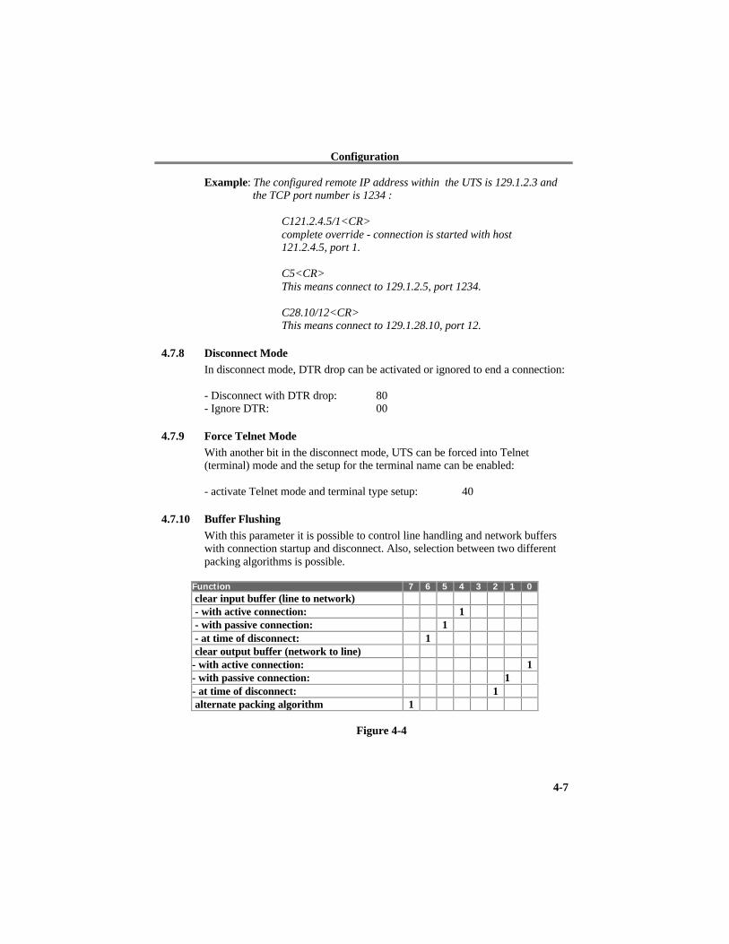
4.7.10 Buffer FlushingWith this parameter it is possible to control line handling and network bufferswith connection startup and disconnect. Also, selection between two differentpacking algorithms is possible.
Function 7 6 5 4 3 2 1 0 clear input buffer (line to network) - with active connection: 1 - with passive connection: 1 - at time of disconnect: 1 clear output buffer (network to line)- with active connection: 1- with passive connection: 1- at time of disconnect: 1 alternate packing algorithm 1
Figure 4-4

Configuration
4-8
4.7.11 Inactivity TimeoutWith these parameters an inactivity time can be set. If the set time expireswithout an activity on the serial line, the connection is dropped.
4.7.12 Pack Control(Version 2.80 and above) Alternative pack algorithm settings are controlledhere. Set this value to 00 if specific functions are not needed.The functions of these bits are defined in the following table:
Function 7 6 5 4 3 2 1 0
Idle time to force transmit: 12ms (avg.) 0 0
Idle time to force transmit: 52ms (avg.) 0 1
Idle time to force transmit: 250ms (avg.) 1 0
Idle time to force transmit: 5 secs (!) 1 1
No trailing chars after sendchar(s) 0 0
One trailing char after sendchar(s) 0 1
Two trailing chars after sendchar(s) 1 0
Sendchars define 2-Byte sequence 1
Send immediate after Sendchar 1
Figure 4-5
“Idle time to force transmit” defines the time period after which all accumulatedcharacters are sent, regardless of the recognition of send characters.In some applications, CRC, Checksum or other trailers follow theend_of_sequence character. In these cases, this option helps to adapt frametransmission to the frame boundary.
If Bit 4 is set, UTS interprets the Sendchars as a 2-byte sequence, if reset, theywill be interpreted independently.
If Bit 5 is not set, any other characters already in the serial buffer will beincluded in the transmission after a “transmit” condition is found. If the bit isset, the UTS will immediately send after recognizing the transmit condition(sendchar or timeout)
NOTE: A transmission might occur if status information has to beexchanged or an acknowledgement has to be sent.
4.7.13 Send CharactersUp to two characters can be entered in hexadecimal representation in theparameters “sendchar.” If a character received on the serial line matches one ofthese characters, it is immediately sent, together with any waiting characters to

Configuration
4-9
the TCP connection. This is especially useful to minimize the response time forspecific protocol characters on the serial line (i.e. ETX, EOT etc.). Setting thefirst Sendchar to “00” disabled the recognition of the characters.
Alternatively, the two characters can be interpreted as a sequence (see Packcontrol, above).
4.7.14 Telnet Terminal TypeThis parameter appears only if terminal type option is enabled by setting Bit 6in the disconnect mode. If set, the terminal name used for the Telnet terminaltype exchange option can be set here. Only one name can be entered.
If Terminal type option is enabled, UTS also reacts to the EOR (end of record)and binary options, which can be used for applications like terminal emulationto IBM hosts (contact Lantronix for details).
4.7.15 Exit Configuration ModeTo leave the configuration program and save all changes, press ‘9’. All valueswill be stored in nonvolatile (E²PROM) memory, and UTS will reset.

Monitor mode and Firmware Upgrade
5-1
5 Monitor Mode and Firmware UpgradeTo enter monitor mode, the same principal as setting the parameters is used (see4.4 Serial Configuration). Instead of entering three “x ” keys, key in “xx1”. TheUTS will respond with a special prompt. A UTS Token Ring needs a workingnetwork connection to enter monitor mode. Because Network functions areneeded for some diagnostics commands, it may take up to 20 seconds until thenetwork part of the UTS is initialized and the prompt is displayed. This isespecially true if an empty Token Ring (or a ring simulator) is used. For asimple ring simulator, see Appendix B. To start the monitor mode withoutnetwork functions, enter “xx2” (new function with Version 2.05 and later).
5.1 Monitor CommandsThe following commands are available in the monitor mode. Many commandshave an IP address as an optional parameter (x.x.x.x). If it is given, thecommand is applied to another UTS with that IP address. If no IP address isgiven, the command is executed locally.
All commands must be given in capital letters; only blanks (spaces) areaccepted between parameters.
DL Firmware download to the UTSSF x.x.x.x Send irmware to UTS with IP x.x.x.xVS x.x.x.x Query software header record (16-byte).GC x.x.x.x Get configuration as HEX recordsSC x.x.x.x Set configuration from HEX recordsPI x.x.x.x Check with Ping if x.x.x.x is alive and reachable.QU Quit - exit diagnostics mode
Command result codes:
0 OK, no error1 No answer from remote device2 Cannot reach remote device or does not answer8 Wrong parameter(s)9 Invalid command
Monitor mode and Firmware Upgrade
5-2
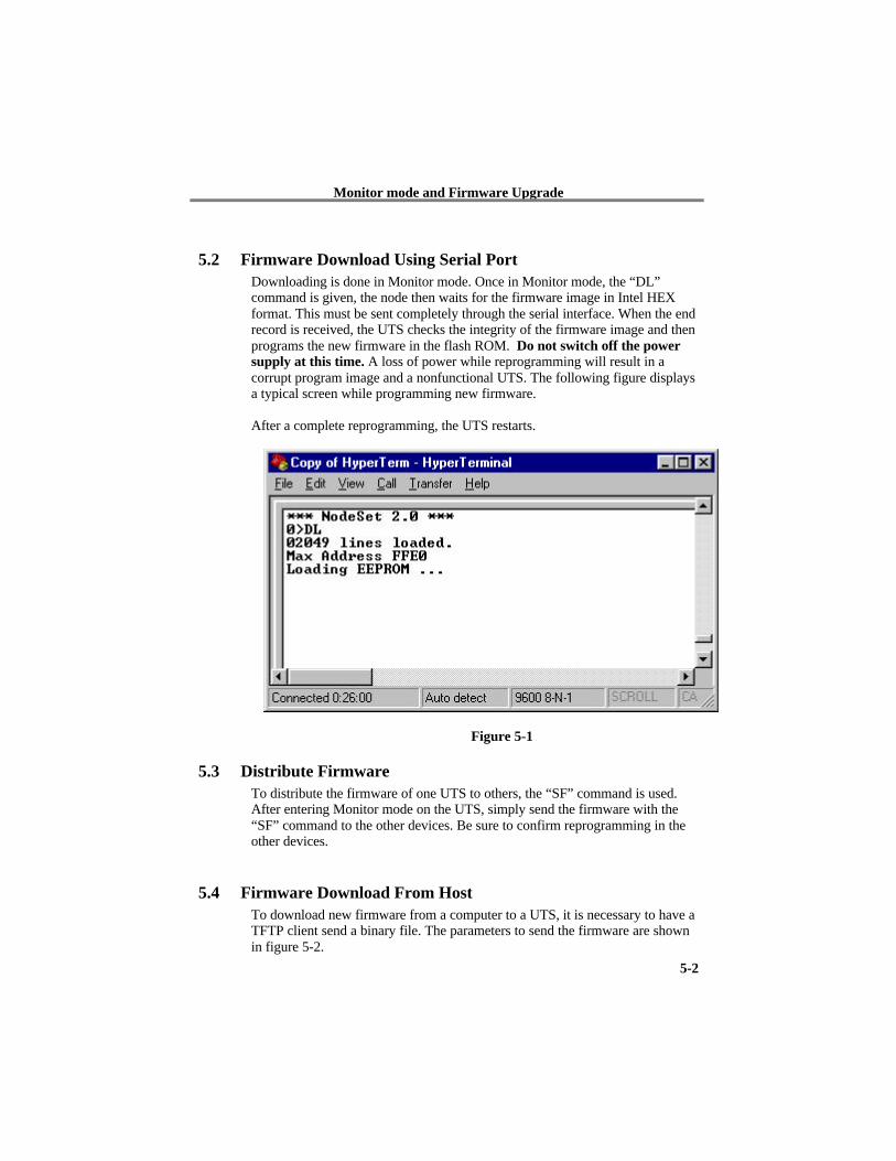
5.2 Firmware Download Using Serial PortDownloading is done in Monitor mode. Once in Monitor mode, the “DL”command is given, the node then waits for the firmware image in Intel HEXformat. This must be sent completely through the serial interface. When the endrecord is received, the UTS checks the integrity of the firmware image and thenprograms the new firmware in the flash ROM. Do not switch off the powersupply at this time. A loss of power while reprogramming will result in acorrupt program image and a nonfunctional UTS. The following figure displaysa typical screen while programming new firmware.
After a complete reprogramming, the UTS restarts.
Figure 5-1
5.3 Distribute FirmwareTo distribute the firmware of one UTS to others, the “SF” command is used.After entering Monitor mode on the UTS, simply send the firmware with the“SF” command to the other devices. Be sure to confirm reprogramming in theother devices.
5.4 Firmware Download From HostTo download new firmware from a computer to a UTS, it is necessary to have aTFTP client send a binary file. The parameters to send the firmware are shownin figure 5-2.

Monitor mode and Firmware Upgrade
5-3
NOTE: The file to be downloaded must be the .ROM (binary) imageand not the hex version! File size should be 32768 or 65536bytes.
Figure 5-2

Serial Line Interfaces
6-1
6 Serial Line Interfaces
6.1 Connector Pinout RS-232C, Channe1 1This connector is available on the UTS External Models. Configuration is DCE(modem-like), 25pin female SubD.
Pin Direction Function
1 None
2 to UTS TxD Transmitted data
3 from UTS RxD Received data
4 to UTS RTS Request to send
5 from UTS CTS Clear to send
6 from UTS DSR Data set ready
7 Ground
8 from UTS DCD Data carrier detect
20 to UTS DTR Data Terminal Ready
Figure 6-1
NOTE: Please make sure that other pins are not connected, as thereare other signals on the connector. Improper wiring of thesepins might damage the UTS.
6.2 Connector Pinout RS-232C Channel 2This connector is available on the UTS External Models. Configuration is PC-like (9pin male DB), but the signals are different due to DCE function.
Pin Direction Function
1 to UTS DTR
2 to UTS TxD Transmitted data
3 from UTS RxD Received data
4 from UTS DCD
5 Ground
7 from UTS CTS
8 to UTS RTS
Figure 6-2

Serial Line Interfaces
6-2
6.3 Connector Pinout RS-422/485This connector is the same as the Channel 1 RS-232 connector for the ExternalUTS Models.
Pin Function
1 None
7 Ground
14 DOUT +
15 DOUT -
21 DIN+
22 DIN -
Figure 6-3
NOTE: For RS-485 2-wire functionality, 14 and 21, as well as 15and 22 must be connected together.
6.4 Line Interface Description
6.4.1 First Channel, RS-232CThe following paragraph addresses the standard UTS. The serial interface of theUTS is designed to be used like a standard DCE (data communicationsequipment) modem.
UTS transmits data received from the network to RxD (pin 3) and sends datareceived on TxD (pin 2) to the network.
Hardware handshake is controlled by means of the signals RTS (pin 4) and CTS(pin 5, UTS-driven). The DSR line (pin 6) is active hardwired.
If a connection to/from the channel is active to a peer on the network, the DCDline (pin 8) is set active.
Connection establishment and disconnect can be controlled with DTR (pin 20).
6.4.2 Secondary RS-232C InterfaceThe secondary interface (used for channel 2) works exactly the same way asdefined for channel 1.

Serial Line Interfaces
6-3
6.4.3 RS-422/485 InterfaceThe RS-422/485 interface is designed for two- or four-wire applications(selectable by one bit in the IF-Mode, interface mode). Only TxD and RxDsignals are available.
When two-wire operation mode is selected, the UTS automatically switches thetransmitter off after the last data byte and suppresses the echo from the line.UTS RS-485 input and output must be connected together externally

Application Examples
7-1
7 Application Examples
7.1 ASCII Terminal to Host for LoginTo connect a DTE (Data Terminal Equipment), a standard non-crossed cablecan be used for port 1.
Channel one is configured for speed, interface mode (typically 4C, N,8,1) andflow control (hardware or XON/XOFF).
TCP port number is a user-selected arbitrary number (10000 is fine). ConnectMode 01 (connect with any character--never accept network initiatedconnections), remote IP Address set to the host, and the remote port number to23 (telnet service).
Flush mode can be set to 80 to select the block-saving packing algorithm, andno buffers are cleared.
A disconnect timeout can be set, whereas the DTR disconnect feature isdisabled (00)
7.2 RS-485 2-wire Prolongation Over NetworkTwo UTSes are used for this application: one at the “local” site and one at the“remote” site. Only Channel 1 can be used because Channel 2 supports onlyRS-232.
Assuming that one device initiates the dialog, the following shows a samplesetting.
Interface mode can be set based on RS-485 on 4-wire or 2-wire applications.See Figure 4-2.
Flow control is usually not used in these applications (set to 00). The portnumber can be any number; it is recommended to use the same value for bothunits at the local and remote sites. (i.e. 10000)
Flush mode should be set to 80 to minimize packet count, unless both UTSesare connected to a local LAN and minimal transmission delay is important.Send Characters can be programmed to Block trailing Characters (like <CR>)to speed up transmission.
Disconnect Mode should be set to 00.

Application Examples
7-2
The Connect mode can be configured similarly on both UTSes, although it isadvisable to declare one side as “master” to activate the connection.
On the master side, the remote IP address and port number MUST be set.Connect mode is typically set to 01 (autoconnect with any character, neveraccept incoming connections), whereas the slave connect mode is set to C0,indicating it will not build up a connection and accept on the network.It is not necessary to set the remote IP address and ports for the slave. If a youwant a symmetric setup, both connect mode entries should be C1; the remote IPaddress and port have to be set on both units.
7.3 Telnet Server for Device ManagementManagement of workstations, routers and other equipment through Telnetsessions is accomplished by defining the UTS as a Telnet server. The UTSaccepts connections over the network and so “connects” directly to the serialport.
It is necessary to either set the port number to 23 (the Telnet” service standard)or to explicitly enable the Telnet functionality by setting bit6 (hex 40) in thedisconnect mode.Recommended settings:
Connect Mode: C0 (or 40 if inactive DTR signals that the device is notavailable)Disconnect Mode: 40 (to enable telnet server)Flush Mode: 80Sendchars: 0A 0A (line feed)
The interface mode will usually be 4C (N81, RS.232)Example: PC or ASCII Terminal to UTS
7.4 Printer ConnectionThe UTS does not support LPD/LPR spooling systems. In order to use the UTSas a serial print server, your operating system/application must support TCPsocket connections.
A serial printer is usually wired like a DTE device. Different printers havedifferent pin configurations, so be sure to check your printer manual for thecorrect pinouts.
The signal goes low if the printer is unable to accept more data (e.g. the printerbuffer is full). It must be connected to the UTS’ RTS input. Depending on themodel, the flow control signals are:
RTS (standard)
Application Examples
7-3
DTR (widespread, named ”Busy” most times)TXD
7.4.1 Software HandshakeIf a device uses a software handshake, it is unnecessary to connect the RTS andCTS wires. It may be advisable to jumper the inputs to “always active”.
7.4.2 Printer Ready SignalIf a DTE (printer) has a “ready”- signal (paper installed etc.), it can be used todeny the connection if not ready. In this case, this signal must be connected tothe UTS DTR signal, and the connection setup should be set to “accept onlywith active DTR”.

LED Status Display
8-1
8 LED Status DisplayDepending on the model, three different LEDs display the status of the UTS.Most models also have some network diagnostic LEDs (such as Good Link(GL), Receive (RX), Transmit (TX), Collision (CL). They are labeled on thefront.
8.1 Yellow and Green LEDThe green LED displays the status of Channel 1; the yellow LED displays thestatus of Channel 2 (the red LED will be off while in normal operation).
Stable color: Channel idle, no connection
Blinking, 1 sec cycle:Connected over the network
8.2 Red LEDIf the red LED is on or blinking, the green LED will give a diagnostics code.There is a fatal error, and the UTS is not working.
Red LED stable on, green LED blinking:
1x: EPROM-checksum error2x: RAM-error3x Network controller error (Token Ring)4x: E²PROM checksum error or bad5x: IP address already used on network
Red LED blinking, green LED blinking:
4x: The network connection is faulty. This code should onlyappear after power up. Even though the UTS is going intooperation mode, the problem will potentially persist.
5x: No DHCP response was received.

Technical data
9-1
9 Technical DataSome values are for the standard external models only!
9.1 CPU, Memory Controllers:V.40 CPU, 10MHz clockZ85C30 SCC Serial Communications ControllerNational Semiconductor DP839xx Ethernet Controller or TMS340 chipset forToken Ring Version128kByte RAM, 128 or 256kByte Flash PROM256 Byte E²PROM for parameter storage
9.2 Serial Interface25-pin D-shell female connector (DCE pinout)Speed software selectable 300 to 115k baudSoftware selectable RS-232C or RS-422/485Second channel RS-232C interface
9.3 Network Interface15-pin AUI interface (External Ethernet only) for transceiver connection to:
Thick Wire EthernetThinner Ethernetfiber optics
Integrated 10-BaseT port (RJ-45 connector)
9.4 Power SupplyPower Plug (supplied), or 15-30 Volt DC, max. 800mA
9.5 Power Consumptionmax. 9 Watt
9.6 LEDsThree LEDs for channel status displayFour LEDs for network interface status (Ethernet)
9.7 CaseAluminum case, with removable mounting brackets
9.8 Dimensions180 x 155 x 40 mm (7.1 x 6.1 x 1.6 in)
9.9 Weightapprox. 500g without AC power adapter
Token Ring specific
A- Token Ring Specific
A.1 Additional Information for Token Ring VersionsThe following information describes differences for Token Ring versions.
A.1.1 Token Ring Insertion Process Needs TimeWhen the NTS attempts to enter the ring, extensive tests of the ringphysical interface are done before opening the loop. These tests take a fewseconds. After opening the ring, the NTS waits for a token from a ringmaster. If there is no other device in the ring, it may take up to 30 secondsuntil the ring insertion process is completed (and the red LED stopsblinking).
A.2 Network InterfaceThe Token Ring version of UTS has a standard D-Shell 9pin femaleconnector (STP) to be connected to standard Token Ring drop cables and anRJ-45 connector (UTP) to be connected to an UTP Token Ring MAU. Theused connector will be automatically detected. The ring interface speed isconfigured by a jumper to prevent accidental configuration. The jumper canbe set through a hole in the back of the case. The factory setting of thisjumper is 16Mbit.

Token Ring specific
A.3 Token Ring SimulatorThe following schematic defines a simple Token Ring simulator that can beused to test the NTS Network interface without a MAU.
Figure A-1

IP Addresses, Netmask etc.
B- IP Addresses, Netmask etc.
B.1 IP AddressingAn IP address is a 32-bit value, divided into four octets of eight bits each.The standard representation is four decimal numbers (in the range of0..255), divided by dots.Example: 192.2.1.123
This is called decimal-dot notation.
The IP address is divided in two parts: network and host. To supportdifferent needs, three ”network classes” have been defined. Depending onthe network class, the last one, two or three bytes define the host, while theremaining part defines the network. In the following, ‘x’ stands for the hostpart of the IP address:
B.2 Class A NetworkIP address 1.x.x.x to 127.x.x.x
Only 127 different networks of this class exist. These have a very largenumber of potential connected devices (up to 16,777,216)Example: 10.0.0.1, (network 10, host 0.0.1)
B.3 Class B NetworkIP address 128.0.x.x to 191.255.xxx.xxx
These networks are used for large company networks. Every network canconsist of up to 65,534 devices.
Example: 172.1.3.2 (network 172.1, host 3.2)
B.4 Class C NetworkIP address 192.0.0.xxx to 223.255.255.xxx
These network addresses are most common and are often used in smallcompanies. These networks can consist of a maximum number of 254 hosts.Example: 192.7.1.9 (network 192.7.1, host 9)

IP Addresses, Netmask etc.
The remaining addresses 224.x.x.x - 239.x.x.x are defined as ”class D” andare used as a multicast addresses.
The addresses 240.x.x.x. - 254.x.x.x are defined as "class E" and arereserved addresses.
B.5 Network AddressThe host address with all host bits set to "0" is used to address the networkas a whole (in routing entries, for example).
B.6 Broadcast AddressThe address with the host part bits set to ‘1” is the broadcast address,meaning “for every station”.
Network and Broadcast addresses must not be used as a host address (e.g.192.168.0.0 identifies the entire network, 192.168.0.255 identifies thebroadcast address).
B.7 IP NetmaskThe netmask is used to divide the IP address differently from the standarddefined by the classes A, B, C. A netmask defines how many bits from theIP address are to be taken as the network section and how many bits are tobe taken as the host section.
B.7.1 Standard IP Network Netmask:
Network Bits Host Bits NetmaskClass A 8 24 255.0.0.0
Class B 16 16 255.255.0.0
Class C 24 8 255.255.255.0
Figure B-1
The number of host bits is entered; the NTS then calculates the netmask.The netmask is displayed in standard decimal-dot notation.

IP Addresses, Netmask etc.
B.7.2 Netmask Examples
Netmask Host bits
255.255.255.252 2
255.255.255.248 3
255.255.255.240 4
255.255.255.224 5
255.255.255.192 6
255.255.255.128 7
255.255.255.0 8
255.255.254.0 9
255.255.252.0 10
255.255.248.0 11
. .
. .
255.128.0.0 23
255.0.0.0 24
Figure B-2
B.7.3 Private IP Networks and the InternetIf your network is not connected to the Internet and there are no plans tomake such a connection you may use any IP address you wish.
If you are not connected to the Internet and have plans to connect, or youare connected to the Internet and want to operate your NTSes on an Intranetyou should use one of the sub-networks below. These network numbershave been reserved for such networks. If you have any questions about IPassignment consult your Network Administrator.
Class A 10.x.x.xClass B 172.16.x.xClass C 192.168.0.x
IP Addresses, Netmask etc.
B.7.4 Network RFC’sFor more information regarding IP addressing see the following documents.These can be located on the World Wide Web using one of the directoriesor indices:
RFC 950 Internet Standard Subnetting ProcedureRFC 1700 Assigned NumbersRFC 1117 Internet NumbersRFC 1597 Address Allocation for Private Internets

Binary to HEX Conversion
C- Binary to HEX ConversionHexadecimal digits have values from 0..15, represented as 0...9, A (for 10),B (for 11) ... F (for 15). The following table can serve as a conversion chartbin - dec. - hex:
C.1 Bin/DEC/Hex Table
Decimal Binary Hexadecimal
0 0000 0
1 0001 1
2 0010 2
3 0011 3
4 0100 4
5 0101 5
6 0110 6
7 0111 7
8 1000 8
9 1001 9
10 1010 A
11 1011 B
12 1100 C
13 1101 D
14 1110 E
15 1111 F
Figure C-1
To convert a binary value to a hexadecimal representation, the upper andlower four bits are treated separately, resulting in a two-digit hexadecimalnumber.

Warranty Statement
Lantronix warrants for a period of FIVE YEARS from the date ofshipment that each CoBox server supplied shall be free from defects inmaterial and workmanship. During this period, if the customerexperiences difficulties with a product and is unable to resolve theproblem by phone with Lantronix Technical Support, a ReturnMaterial Authorization (RMA) will be issued. Following receipt of aRMA number, the customer is responsible for returning the product toLantronix, freight prepaid. Lantronix, upon verification of warrantywill, at its option, repair or replace the product in question, and returnit to the customer freight prepaid. No services are handled at thecustomer's site under this warranty.
Lantronix warrants software for a period of sixty (60) days from thedate of shipment that each software package supplied shall be freefrom defects and shall operate according to Lantronix specifications.Any software revisions required hereunder cover supply of distributionmedia only and do not cover, or include, any installation. Thecustomer is responsible for return of media to Lantronix and Lantronixfor freight associated with replacement media being returned to thecustomer.
Lantronix shall have no obligation to make repairs or to causereplacement required through normal wear and tear of necessitated inwhole or in part by catastrophe, fault or negligence of the user,improper or unauthorized use of the Product, or use of the Product insuch a manner for which it was not designed, or by causes external tothe Product, such as, but not limited to, power or failure of airconditioning.
There are no understandings, agreements, representations orwarranties, express or implied, including warranties of merchantabilityor fitness for a particular purpose, other than those specifically set outabove or by any existing contract between the parties. Any suchcontract states the entire obligation of Lantronix. The contents of thisdocument shall not become part of or modify any prior or existingagreement, commitment or relationship
The information, recommendation, description and safety notations inthis or other documents supplied by Lantronix are based on generalindustry experience and judgment with respect to such hardware andsoftware. THIS INFORMATION SHOULD NOT BE CONSIDEREDTO BE ALL INCLUSIVE OR COVERING ALL CONTINGENCIES.
NO OTHER WARRANTIES, EXPRESS OR IMPLIED,INCLUDING WARRANTIES OF FITNESS FOR A PARTICULARPURPOSE OR MERCHANTABILITY, OR WARRANTIESARISING FROM COURSE OF DEALING OR USAGE OF TRADE,ARE MADE REGARDING THE INFORMATION,RECOMMENDATIONS, DESCRIPTIONS AND SAFETYNOTATIONS CONTAINED HEREBY AND IN HARDWARE ANDSOFTWARE SPECIFICATION DOCUMENTATION, ORINSTRUCTIONS SUPPLIED BY LANTRONIX. In no event willLantronix be responsible to the user in contract, in tort (includingnegligence), strict liability or otherwise for any special, indirect,incidental or consequential damage or loss of equipment, plant orpower system, cost of capital, loss of profits or revenues, cost ofreplacement power, additional expenses in the use of existingsoftware, hardware, equipment or facilities, or claims against the userby its employees or customers resulting from the use of theinformation, recommendations, descriptions and safety notationssupplied by Lantronix. Lantronix liability is limited (at its election) to(1) refund of buyer's purchase price for such affected products(without interest); (2) repair of such products, or (3) replacement ofsuch products, provided however, that the buyer follows theprocedures set forth herein
Warranty claims must be received by Lantronix within the applicablewarranty period. A replaced product, or part thereof, shall become theproperty of Lantronix and shall be returned to Lantronix at thePurchaser's expense. ALL RETURN MATERIAL MUST BEACCOMPANIED BY A RETURN MATERIAL AUTHORIZATIONNUMBER ASSIGNED BY LANTRONIX.
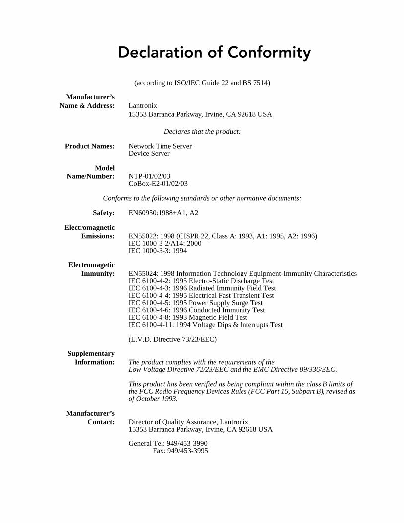
Declaration of Conformity
(according to ISO/IEC Guide 22 and BS 7514)
Manufacturer’sName & Address: Lantronix
15353 Barranca Parkway, Irvine, CA 92618 USA
Declares that the product:
Product Names: Network Time ServerDevice Server
ModelName/Number: NTP-01/02/03
CoBox-E2-01/02/03
Conforms to the following standards or other normative documents:
Safety: EN60950:1988+A1, A2
ElectromagneticEmissions: EN55022: 1998 (CISPR 22, Class A: 1993, A1: 1995, A2: 1996)
IEC 1000-3-2/A14: 2000IEC 1000-3-3: 1994
ElectromageticImmunity: EN55024: 1998 Information Technology Equipment-Immunity Characteristics
IEC 6100-4-2: 1995 Electro-Static Discharge TestIEC 6100-4-3: 1996 Radiated Immunity Field TestIEC 6100-4-4: 1995 Electrical Fast Transient TestIEC 6100-4-5: 1995 Power Supply Surge TestIEC 6100-4-6: 1996 Conducted Immunity TestIEC 6100-4-8: 1993 Magnetic Field TestIEC 6100-4-11: 1994 Voltage Dips & Interrupts Test
(L.V.D. Directive 73/23/EEC)
SupplementaryInformation: The product complies with the requirements of the
Low Voltage Directive 72/23/EEC and the EMC Directive 89/336/EEC.
This product has been verified as being compliant within the class B limits of the FCC Radio Frequency Devices Rules (FCC Part 15, Subpart B), revised as of October 1993.
Manufacturer’sContact: Director of Quality Assurance, Lantronix
15353 Barranca Parkway, Irvine, CA 92618 USA
General Tel: 949/453-3990Fax: 949/453-3995