installation guide for acme 4600
TRANSCRIPT
8/15/2019 Installation guide for ACME 4600
http://slidepdf.com/reader/full/installation-guide-for-acme-4600 1/132
Acme Packet 4600
Hardware Installation and Maintenance Guide
April 2015

8/15/2019 Installation guide for ACME 4600
http://slidepdf.com/reader/full/installation-guide-for-acme-4600 2/132
Copyright © 2014, 2015 Oracle and/or its affiliates. All rights reserved.
This software and related documentation are provided under a license agreement containing restrictions on use anddisclosure and are protected by intellectual property laws. Except as expressly permitted in your license agreement orallowed by law, you may not use, copy, reproduce, translate, broadcast, modify, license, transmit, distribute, exhibit,
perform, publish, or display any part, in any form, or by any means. Reverse engineering, disassembly, ordecompilation of this software, unless required by law for interoperability, is prohibited.
The information contained herein is subject to change without notice and is not warranted to be error-free. If you findany errors, please report them to us in writing.
If this is software or related documentation that is delivered to the U.S. Government or anyone licensing it on behalf ofthe U.S. Government, the following notice is applicable:
U.S. GOVERNMENT END USERS: Oracle programs, including any operating system, integrated software, any programs installed on the hardware, and/or documentation, delivered to U.S. Government end users are "commercialcomputer software" pursuant to the applicable Federal Acquisition Regulation and agency-specific supplementalregulations. As such, use, duplication, disclosure, modification, and adaptation of the programs, including anyoperating system, integrated software, any programs installed on the hardware, and/or documentation, shall be subjectto license terms and license restrictions applicable to the programs. No other rights are granted to the U.S. Government.
This software or hardware is developed for general use in a variety of information management applications. It is notdeveloped or intended for use in any inherently dangerous applications, including applications that may create a risk of
personal injury. If you use this software or hardware in dangerous applications, then you shall be responsible to take allappropriate fail-safe, backup, redundancy, and other measures to ensure its safe use. Oracle Corporation and itsaffiliates disclaim any liability for any damages caused by use of this software or hardware in dangerous applications.
Oracle and Java are registered trademarks of Oracle and/or its affiliates. Other names may be trademarks of theirrespective owners.
Intel and Intel Xeon are trademarks or registered trademarks of Intel Corporation. All SPARC trademarks are usedunder license and are trademarks or registered trademarks of SPARC International, Inc. AMD, Opteron, the AMD logo,and the AMD Opteron logo are trademarks or registered trademarks of Advanced Micro Devices. UNIX is a registeredtrademark of The Open Group.
This software or hardware and documentation may provide access to or information on content, products, and servicesfrom third parties. Oracle Corporation and its affiliates are not responsible for and expressly disclaim all warranties ofany kind with respect to third-party content, products, and services. Oracle Corporation and its affiliates will not beresponsible for any loss, costs, or damages incurred due to your access to or use of third-party content, products, orservices unless otherwise set forth in an applicable agreement between you and Oracle. Oracle Corporation and itsaffiliates will not be responsible for any loss, costs, or damages incurred due to your access to or use of third-partycontent, products, or services, except as set forth in an applicable agreement between you and Oracle.
8/15/2019 Installation guide for ACME 4600
http://slidepdf.com/reader/full/installation-guide-for-acme-4600 3/132
Acme Packet 4600 Hardware Installation and Maintenance Guide iii
Contents
About This Guide. . . . . . . . . . . . . . . . . . . . . . . . . . . . . . . . . . . . . . . . . . . . . . . . . .vii
Overview . . . . . . . . . . . . . . . . . . . . . . . . . . . . . . . . . . . . . . . . . . . . . . . . . . . . . . . . . . . . . . . . . . . . . . vii
Revision History . . . . . . . . . . . . . . . . . . . . . . . . . . . . . . . . . . . . . . . . . . . . . . . . . . . . . . . . . . . . . . . . vii
1 Safety . . . . . . . . . . . . . . . . . . . . . . . . . . . . . . . . . . . . . . . . . . . . . . . . . . . . . . . . . . . . . 7
Introduction. . . . . . . . . . . . . . . . . . . . . . . . . . . . . . . . . . . . . . . . . . . . . . . . . . . . . . . . . . . . . . . . . . . . . .7Environmental, Safety, and Regulatory Certifications . . . . . . . . . . . . . . . . . . . . . . . . . . . . . . . . .7
General Safety Precautions . . . . . . . . . . . . . . . . . . . . . . . . . . . . . . . . . . . . . . . . . . . . . . . . . . . . . . . .7
Electrical Safety Precautions . . . . . . . . . . . . . . . . . . . . . . . . . . . . . . . . . . . . . . . . . . . . . . . . . . . . . . .8
Battery Warning . . . . . . . . . . . . . . . . . . . . . . . . . . . . . . . . . . . . . . . . . . . . . . . . . . . . . . . . . . . . . . . . . .8
ESD Safety . . . . . . . . . . . . . . . . . . . . . . . . . . . . . . . . . . . . . . . . . . . . . . . . . . . . . . . . . . . . . . . . . . . . . . .9
2 Component Overview. . . . . . . . . . . . . . . . . . . . . . . . . . . . . . . . . . . . . . . . . . . . . . 11
Chassis . . . . . . . . . . . . . . . . . . . . . . . . . . . . . . . . . . . . . . . . . . . . . . . . . . . . . . . . . . . . . . . . . . . . . . . . .11
System Processor . . . . . . . . . . . . . . . . . . . . . . . . . . . . . . . . . . . . . . . . . . . . . . . . . . . . . . . . . . . . . . . .13
System Control Panels . . . . . . . . . . . . . . . . . . . . . . . . . . . . . . . . . . . . . . . . . . . . . . . . . . . . . . . . . . .13
Network Interface Unit . . . . . . . . . . . . . . . . . . . . . . . . . . . . . . . . . . . . . . . . . . . . . . . . . . . . . . . . . . .15
SFP/SFP+ Transceivers . . . . . . . . . . . . . . . . . . . . . . . . . . . . . . . . . . . . . . . . . . . . . . . . . . . . . . . . . . .22
Media Cables. . . . . . . . . . . . . . . . . . . . . . . . . . . . . . . . . . . . . . . . . . . . . . . . . . . . . . . . . . . . . . . . . . . .23
Power Components . . . . . . . . . . . . . . . . . . . . . . . . . . . . . . . . . . . . . . . . . . . . . . . . . . . . . . . . . . . . . .24
Cooling Components. . . . . . . . . . . . . . . . . . . . . . . . . . . . . . . . . . . . . . . . . . . . . . . . . . . . . . . . . . . . .27
3 Graphic Display . . . . . . . . . . . . . . . . . . . . . . . . . . . . . . . . . . . . . . . . . . . . . . . . . . . 29
Graphic Display . . . . . . . . . . . . . . . . . . . . . . . . . . . . . . . . . . . . . . . . . . . . . . . . . . . . . . . . . . . . . . . . .29
Display Modes . . . . . . . . . . . . . . . . . . . . . . . . . . . . . . . . . . . . . . . . . . . . . . . . . . . . . . . . . . . . . . . . . .30
Graphic Display Menus . . . . . . . . . . . . . . . . . . . . . . . . . . . . . . . . . . . . . . . . . . . . . . . . . . . . . . . . . .30
Graphic Display Output for HA Nodes . . . . . . . . . . . . . . . . . . . . . . . . . . . . . . . . . . . . . . . . . . . . .34
8/15/2019 Installation guide for ACME 4600
http://slidepdf.com/reader/full/installation-guide-for-acme-4600 4/132
iv Acme Packet 4600 Hardware Installation and Maintenance Guide
4 System Installation . . . . . . . . . . . . . . . . . . . . . . . . . . . . . . . . . . . . . . . . . . . . . . . . 37
Introduction. . . . . . . . . . . . . . . . . . . . . . . . . . . . . . . . . . . . . . . . . . . . . . . . . . . . . . . . . . . . . . . . . . . . .37
Shipped Parts . . . . . . . . . . . . . . . . . . . . . . . . . . . . . . . . . . . . . . . . . . . . . . . . . . . . . . . . . . . . . . . . . . .37
Pre-Installation Guidelines . . . . . . . . . . . . . . . . . . . . . . . . . . . . . . . . . . . . . . . . . . . . . . . . . . . . . . .38
Mounting Installation . . . . . . . . . . . . . . . . . . . . . . . . . . . . . . . . . . . . . . . . . . . . . . . . . . . . . . . . . . . .39
Cabinet-style 4-Post Chassis Installation . . . . . . . . . . . . . . . . . . . . . . . . . . . . . . . . . . . . . . . . . . .42
Center-Mount 2-Post Chassis Installation . . . . . . . . . . . . . . . . . . . . . . . . . . . . . . . . . . . . . . . . . .50
Fan Module Installation . . . . . . . . . . . . . . . . . . . . . . . . . . . . . . . . . . . . . . . . . . . . . . . . . . . . . . . . . .51
Ground and Power Cable Installationq. . . . . . . . . . . . . . . . . . . . . . . . . . . . . . . . . . . . . . . . . . . . .51
Cabling the Acme Packet 4600 System . . . . . . . . . . . . . . . . . . . . . . . . . . . . . . . . . . . . . . . . . . . . .56
Cabling for HA Deployments . . . . . . . . . . . . . . . . . . . . . . . . . . . . . . . . . . . . . . . . . . . . . . . . . . . . .61
5 Startup . . . . . . . . . . . . . . . . . . . . . . . . . . . . . . . . . . . . . . . . . . . . . . . . . . . . . . . . . . . 65
Introduction. . . . . . . . . . . . . . . . . . . . . . . . . . . . . . . . . . . . . . . . . . . . . . . . . . . . . . . . . . . . . . . . . . . . .65
Creating a Console Connection. . . . . . . . . . . . . . . . . . . . . . . . . . . . . . . . . . . . . . . . . . . . . . . . . . . .65
Powering On the Acme Packet 4600 System. . . . . . . . . . . . . . . . . . . . . . . . . . . . . . . . . . . . . . . . .66
Initial Log on . . . . . . . . . . . . . . . . . . . . . . . . . . . . . . . . . . . . . . . . . . . . . . . . . . . . . . . . . . . . . . . . . . . .66
6 Maintenance . . . . . . . . . . . . . . . . . . . . . . . . . . . . . . . . . . . . . . . . . . . . . . . . . . . . . . 69
Introduction. . . . . . . . . . . . . . . . . . . . . . . . . . . . . . . . . . . . . . . . . . . . . . . . . . . . . . . . . . . . . . . . . . . . .69
System Shutdown . . . . . . . . . . . . . . . . . . . . . . . . . . . . . . . . . . . . . . . . . . . . . . . . . . . . . . . . . . . . . . .69
Rebooting, Resetting, and Power Cycling . . . . . . . . . . . . . . . . . . . . . . . . . . . . . . . . . . . . . . . . . . .70
Standby State for HA Nodes . . . . . . . . . . . . . . . . . . . . . . . . . . . . . . . . . . . . . . . . . . . . . . . . . . . . . .71Chassis Removal. . . . . . . . . . . . . . . . . . . . . . . . . . . . . . . . . . . . . . . . . . . . . . . . . . . . . . . . . . . . . . . . .75
Power Supply Removal and Replacement . . . . . . . . . . . . . . . . . . . . . . . . . . . . . . . . . . . . . . . . . .77
NIU Removal and Replacement . . . . . . . . . . . . . . . . . . . . . . . . . . . . . . . . . . . . . . . . . . . . . . . . . . .79
Replacing the SSM3 Module . . . . . . . . . . . . . . . . . . . . . . . . . . . . . . . . . . . . . . . . . . . . . . . . . . . . . .83
Replacing Transcoder DSP Modules . . . . . . . . . . . . . . . . . . . . . . . . . . . . . . . . . . . . . . . . . . . . . . .87
Upgrading or Replacing a Solid State Drive. . . . . . . . . . . . . . . . . . . . . . . . . . . . . . . . . . . . . . . . .91
Fan and Air Filter Maintenance. . . . . . . . . . . . . . . . . . . . . . . . . . . . . . . . . . . . . . . . . . . . . . . . . . .101
Optical Transceiver Removal and Replacement . . . . . . . . . . . . . . . . . . . . . . . . . . . . . . . . . . . .106
Alarms . . . . . . . . . . . . . . . . . . . . . . . . . . . . . . . . . . . . . . . . . . . . . . . . . . . . . . . . . . . . . . . . . . . . . . . .108
8/15/2019 Installation guide for ACME 4600
http://slidepdf.com/reader/full/installation-guide-for-acme-4600 5/132

8/15/2019 Installation guide for ACME 4600
http://slidepdf.com/reader/full/installation-guide-for-acme-4600 6/132
vi Acme Packet 4600 Hardware Installation and Maintenance Guide
8/15/2019 Installation guide for ACME 4600
http://slidepdf.com/reader/full/installation-guide-for-acme-4600 7/132
Acme Packet 4600 Hardware Installation and Maintenance Guide vii
About This Guide
OverviewThe Acme Packet 4600 System is a high performance, high capacity session bordercontroller that optimally delivers interactive communications — voice, video, andmultimedia sessions — across wireline, wireless, and cable IP network borders. Withits compact single unit 1U design the Acme Packet 4600 System provides exceptionalfunctionality in a tightly integrated system. This chapter provides an introductionand overview of the main components of the Acme Packet 4600 System.
The Acme Packet 4600 System Hardware Installation Guide describes:
• Component overview
• Graphic display and its usage
• System installation
• Startup
• Maintenance
• Safety
• Glossary
Audience This guide is written for network administrators, telecommunications equipmentinstallers and technicians. It provides information related to the hardwarecomponents, features, installation, start-up, and operation of the Acme Packet 4600System. Only experienced and authorized personnel should perform installation,configuration, and maintenance tasks.
Revision History
This section contains a revision history for this document.
Date Description
October 2014 • Initial Release
January 2015 • Renamed the document Acme Packet 4600
Installation and Maintenance Guide.
• Removed Regulatory Specifications and
Certifications from Chapter 7- Specifications.
• Inserted reference to Acme Packet Platforms
Safety and Compliance Guide.
• Removed section of the Maintenance Chapter
on removing and installing SODIMMs.

8/15/2019 Installation guide for ACME 4600
http://slidepdf.com/reader/full/installation-guide-for-acme-4600 8/132
viii Acme Packet 4600 Hardware Installation and Maintenance Guide
March 2015 • Added a section on the installation of
transceivers on the signalling and media ports,
• Corrected ambiguities concerning the speeds
of the signalling and media ports.
April 2015 • Entered notes pointing out that after you
initially install the Acme Packet 4600 or
replace the Solid State Drive (SSD), you mustformat the drive.
• Inserted caveats to confirm that Acme Packet
hardware installation documentation satisfies
NEBS (Network Equipment-Building System)
requirements.
Date Description
8/15/2019 Installation guide for ACME 4600
http://slidepdf.com/reader/full/installation-guide-for-acme-4600 9/132
Acme Packet 4600 Hardware Installation and Maintenance Guide 7
1 Safety
IntroductionThis chapter provides an overview of the recommended safety precautions forinstalling the Acme Packet 4600 System.
Before you install your Acme Packet 4600 System, Oracle recommends that youreview the contents of this chapter and the Installation chapter. Both chaptersprovide information intended to protect you and your Acme Packet 4600 Systemfrom experiencing any harm during the installation process. These chapters alsoprovide information that helps to keep your Acme Packet 4600 System functioningproperly and prevent damage.
Environmental, Safety, and Regulatory CertificationsFor information regarding safety and regulatory certifications applicable to the AcmePacket 4600, refer to the Acme Packet Platforms Safety and Compliance Guide.
General Safety Precautions
To ensure general safety, follow the safety precautions listed in this section.
Fan Module To avoid overheating the system, do not block the air inlets or the fan module, orotherwise obstruct airflow to the system. Keep the area around the Acme Packet
4600 System clean and clutter-free.
SystemMaintenance
Aside from the fan module, power supply, air filter and NIUs, there are no user-serviceable parts inside the Acme Packet 4600 System chassis. Only professionalstrained to maintain, adjust, or repair the Acme Packet 4600 System may providethese services.
Fiber Optic Cable Looking into a fiber optic cable can cause eye damage. Never look directly into theend of the fiber optic cables. Instead, use a fiber optic power meter to determine ifpower is present.
EnvironmentalSpecifications
Adhere to the stated environmental specifications for the Acme Packet 4600.
8/15/2019 Installation guide for ACME 4600
http://slidepdf.com/reader/full/installation-guide-for-acme-4600 10/132
8 Acme Packet 4600 Hardware Installation and Maintenance Guide
Using This Guide Read and understand all notes of warning and caution included in the Acme Packet4600 System documentation. These warnings and cautions are designed to keep yousafe and protect the Acme Packet 4600 System from damage.
Electrical Safety Precautions
To protect yourself from harm and the Acme Packet 4600 System from damage,
follow these electrical safety precautions:
Precautions • Note the locations of the System Power switch on the Acme Packet 4600 and thelocation of the emergency power-off switch for the room where the AcmePacket 4600 is located.
• If an electrical accident occurs, remove power from the system immediately byunplugging the chassis.
• Always disconnect the power from the system when removing a Acme Packet4600 System from its rack.
• When disconnecting power:
• Turn the System Power switch to the Stby position.• Disconnect the circuit breaker at the rack.
• Unplug or unscrew the power cords from the power supplies.
• Use grounded AC power cords that are plugged into grounded electrical outlets.
• Never use extension cords to power a Acme Packet 4600.
• Ensure that the installation facilities have proper grounding systems and includea grounded rack structure or local grounding bus bar.
• When installing the Acme Packet 4600 System in an equipment rack, alwaysmake the ground connection first and disconnect it last when removing it.
• Use shielded Category 5e or 6, RJ45 cables for all 10/100/1000 Ethernet
connections to protect the Acme Packet 4600 System from potential damage.• To avoid making a complete circuit (which causes electrical shock), use only one
hand when working with powered-on electrical equipment.
• Use caution when using electrically conductive tools around the Acme Packet4600 System.
• Remove jewelry before working on the Acme Packet 4600 System.
Battery Warning
Caution: There is a risk of explosion if the battery is replaced by an
incorrect type. Dispose of used batteries according to the
instructions.
8/15/2019 Installation guide for ACME 4600
http://slidepdf.com/reader/full/installation-guide-for-acme-4600 11/132
Acme Packet 4600 Hardware Installation and Maintenance Guide 9
Caution: Perchlorate Material — Special handling may apply. See
www.dtsc.ca.gov/hazardouswaste/perchlorate.
ESD SafetyTo protect the Acme Packet 4600 System’s delicate electronic components fromdamage from static electricity, always follow the appropriate ESD procedures and wear the proper protective devices (such as an ESD wrist strap) when handling anyand all Acme Packet 4600 System hardware and while performing any Acme Packet4600 System hardware procedures.
Precautions To protect your equipment from ESD, follow these ESD safety precautions:
• Ensure that the Acme Packet 4600 System is properly grounded.
• If you are grounding your Acme Packet 4600 System to an electrically
conductive, grounded rack, check to see whether or not the rack is painted. Paintcan hinder proper grounding. If your equipment rack is painted, you shouldground the system to some other reliable place or remove a small portion ofpaint for proper grounding.
• Use a grounded ESD wrist strap when working on the Acme Packet 4600System to prevent static discharge.
• To avoid damaging ESD-sensitive hardware, discharge all static electricity from your body before working directly with the Acme Packet 4600 System chassis bytouching a grounded object.

8/15/2019 Installation guide for ACME 4600
http://slidepdf.com/reader/full/installation-guide-for-acme-4600 12/132
10 Acme Packet 4600 Hardware Installation and Maintenance Guide
8/15/2019 Installation guide for ACME 4600
http://slidepdf.com/reader/full/installation-guide-for-acme-4600 13/132
Acme Packet 4600 Hardware Installation and Maintenance Guide 11
2 Component Overview
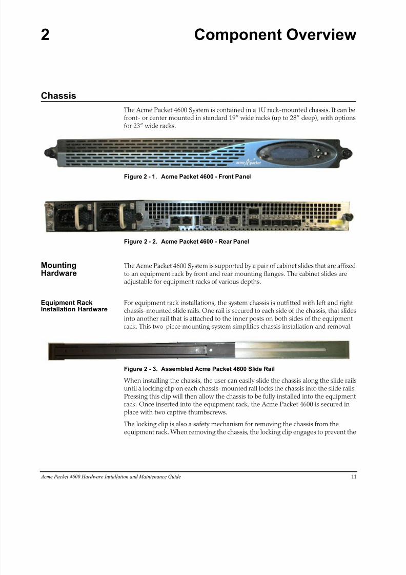
ChassisThe Acme Packet 4600 System is contained in a 1U rack-mounted chassis. It can befront- or center mounted in standard 19” wide racks (up to 28” deep), with optionsfor 23” wide racks.
Figure 2 - 1. Acme Packet 4600 - Front Panel
Figure 2 - 2. Acme Packet 4600 - Rear Panel
MountingHardware
The Acme Packet 4600 System is supported by a pair of cabinet slides that are affixedto an equipment rack by front and rear mounting flanges. The cabinet slides areadjustable for equipment racks of various depths.
Equipment RackInstallation Hardware
For equipment rack installations, the system chassis is outfitted with left and rightchassis-mounted slide rails. One rail is secured to each side of the chassis, that slidesinto another rail that is attached to the inner posts on both sides of the equipmentrack. This two-piece mounting system simplifies chassis installation and removal.
Figure 2 - 3. Assembled Acme Packet 4600 Slide Rail
When installing the chassis, the user can easily slide the chassis along the slide railsuntil a locking clip on each chassis-mounted rail locks the chassis into the slide rails.Pressing this clip will then allow the chassis to be fully installed into the equipment
rack. Once inserted into the equipment rack, the Acme Packet 4600 is secured inplace with two captive thumbscrews.
The locking clip is also a safety mechanism for removing the chassis from theequipment rack. When removing the chassis, the locking clip engages to prevent the
8/15/2019 Installation guide for ACME 4600
http://slidepdf.com/reader/full/installation-guide-for-acme-4600 14/132
12 Acme Packet 4600 Hardware Installation and Maintenance Guide
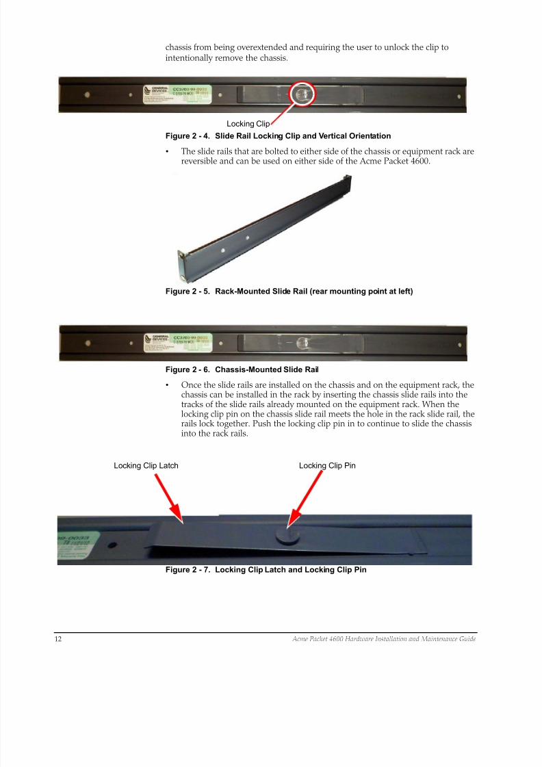
chassis from being overextended and requiring the user to unlock the clip tointentionally remove the chassis.
Locking Clip
Figure 2 - 4. Slide Rail Locking Clip and Vertical Orientation
• The slide rails that are bolted to either side of the chassis or equipment rack arereversible and can be used on either side of the Acme Packet 4600.
Figure 2 - 5. Rack-Mounted Slide Rail (rear mounting point at left)
Figure 2 - 6. Chassis-Mounted Slide Rail
• Once the slide rails are installed on the chassis and on the equipment rack, thechassis can be installed in the rack by inserting the chassis slide rails into the
tracks of the slide rails already mounted on the equipment rack. When thelocking clip pin on the chassis slide rail meets the hole in the rack slide rail, therails lock together. Push the locking clip pin in to continue to slide the chassisinto the rack rails.
Locking Clip Latch Locking Clip Pin
Figure 2 - 7. Locking Clip Latch and Locking Clip Pin
8/15/2019 Installation guide for ACME 4600
http://slidepdf.com/reader/full/installation-guide-for-acme-4600 15/132
Acme Packet 4600 Hardware Installation and Maintenance Guide 13
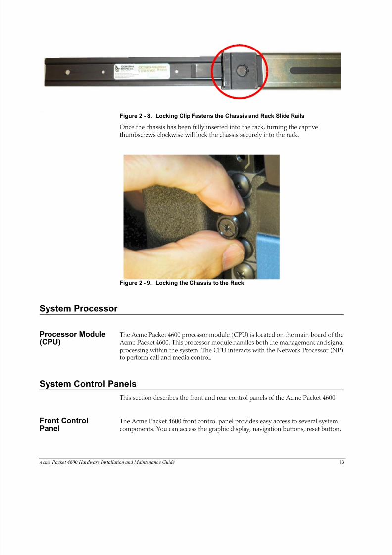
Figure 2 - 8. Locking Clip Fastens the Chassis and Rack Slide Rails
Once the chassis has been fully inserted into the rack, turning the captivethumbscrews clockwise will lock the chassis securely into the rack.
Figure 2 - 9. Locking the Chassis to the Rack
System Processor
Processor Module(CPU)
The Acme Packet 4600 processor module (CPU) is located on the main board of the Acme Packet 4600. This processor module handles both the management and signalprocessing within the system. The CPU interacts with the Network Processor (NP)to perform call and media control.
System Control Panels
This section describes the front and rear control panels of the Acme Packet 4600.
Front ControlPanel
The Acme Packet 4600 front control panel provides easy access to several systemcomponents. You can access the graphic display, navigation buttons, reset button,
8/15/2019 Installation guide for ACME 4600
http://slidepdf.com/reader/full/installation-guide-for-acme-4600 16/132
14 Acme Packet 4600 Hardware Installation and Maintenance Guide
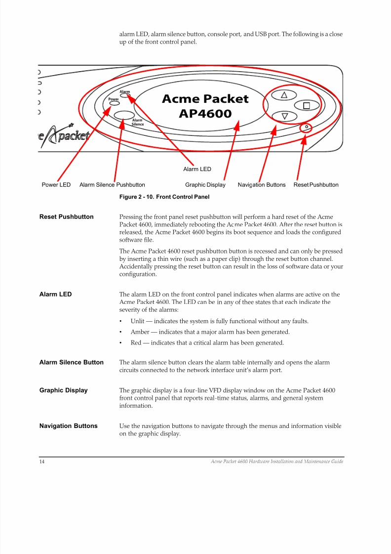
alarm LED, alarm silence button, console port, and USB port. The following is a closeup of the front control panel.
Alarm
Alarm
Power
Silence
Acme Packet
AP4600
Reset Pushbutton
Alarm LED
Power LED Alarm Silence Pushbutton Navigation ButtonsGraphic Display
Figure 2 - 10. Front Control Panel
Reset Pushbutton Pressing the front panel reset pushbutton will perform a hard reset of the AcmePacket 4600, immediately rebooting the Acme Packet 4600. After the reset button isreleased, the Acme Packet 4600 begins its boot sequence and loads the configuredsoftware file.
The Acme Packet 4600 reset pushbutton button is recessed and can only be pressedby inserting a thin wire (such as a paper clip) through the reset button channel. Accidentally pressing the reset button can result in the loss of software data or yourconfiguration.
Alarm LED The alarm LED on the front control panel indicates when alarms are active on the Acme Packet 4600. The LED can be in any of thee states that each indicate theseverity of the alarms:
• Unlit — indicates the system is fully functional without any faults.
• Amber — indicates that a major alarm has been generated.
• Red — indicates that a critical alarm has been generated.
Alarm Silence Button The alarm silence button clears the alarm table internally and opens the alarmcircuits connected to the network interface unit’s alarm port.
Graphic Display The graphic display is a four-line VFD display window on the Acme Packet 4600front control panel that reports real-time status, alarms, and general systeminformation.
Navigation Buttons Use the navigation buttons to navigate through the menus and information visibleon the graphic display.

8/15/2019 Installation guide for ACME 4600
http://slidepdf.com/reader/full/installation-guide-for-acme-4600 17/132
Acme Packet 4600 Hardware Installation and Maintenance Guide 15
Intake Fans Five individual intake fans keep the Acme Packet 4600 cool by blowing air throughthe front panel and exhausting heated air through the rear of the chassis. The intakefans are hot-pluggable and are covered by a particle filter that prevents excess dustand contaminants from entering the system. The particle filter is attached to the rearof the front bezel.
Figure 2 - 11. Intake Fans (shown with front bezel removed)
Rear Panel Power supplies and the network interface unit are located on the rear chassis panel.Rear panel components are described in subsequent sections of this chapter.
Figure 2 - 12. Acme Packet 4600 - Rear Panel with AC Power Supplies
Figure 2 - 13. Acme Packet 4600 - Rear Panel with DC Power Supplies
Network Interface Unit
The single, hot-pluggable network interface unit (NIU) contains all of the AcmePacket 4600 media and management interfaces. The NIU is located on the AcmePacket 4600 rear panel. The Signaling, Media and Network Management interfacesare located on the front panel of the NIU.
Network
Management
Ports
Console
Port
USB
Port
Alarm
Port
Signaling/Media
Interfaces
System
Power
PWR
LED
H/S
LED
Figure 2 - 14. Acme Packet 4600 Network Interface Unit
8/15/2019 Installation guide for ACME 4600
http://slidepdf.com/reader/full/installation-guide-for-acme-4600 18/132
P3P2P1P0P4P5Mgmt 2Mgmt 1Mgmt 0
Management Signaling & Media Ports
16 Acme Packet 4600 Hardware Installation and Maintenance Guide
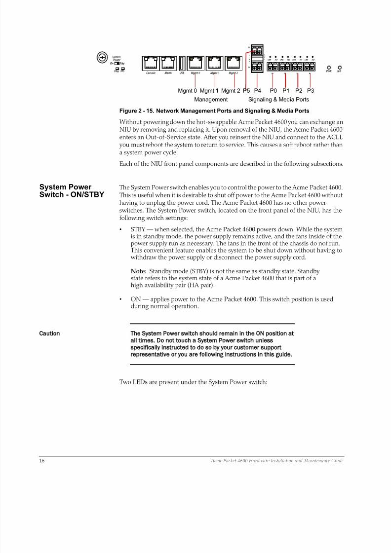
Figure 2 - 15. Network Management Ports and Signaling & Media Ports
Without powering down the hot-swappable Acme Packet 4600 you can exchange anNIU by removing and replacing it. Upon removal of the NIU, the Acme Packet 4600enters an Out-of-Service state. After you reinsert the NIU and connect to the ACLI, you must reboot the system to return to service. This causes a soft reboot rather thana system power cycle.
Each of the NIU front panel components are described in the following subsections.
System Power
Switch - ON/STBY
The System Power switch enables you to control the power to the Acme Packet 4600.
This is useful when it is desirable to shut off power to the Acme Packet 4600 withouthaving to unplug the power cord. The Acme Packet 4600 has no other powerswitches. The System Power switch, located on the front panel of the NIU, has thefollowing switch settings:
• STBY — when selected, the Acme Packet 4600 powers down. While the systemis in standby mode, the power supply remains active, and the fans inside of thepower supply run as necessary. The fans in the front of the chassis do not run.This convenient feature enables the system to be shut down without having to withdraw the power supply or disconnect the power supply cord.
Note: Standby mode (STBY) is not the same as standby state. Standbystate refers to the system state of a Acme Packet 4600 that is part of ahigh availability pair (HA pair).
• ON — applies power to the Acme Packet 4600. This switch position is usedduring normal operation.
Caution The System Power switch should remain in the ON position at
all times. Do not touch a System Power switch unless
specifically instructed to do so by your customer support
representative or you are following instructions in this guide.
Two LEDs are present under the System Power switch:
8/15/2019 Installation guide for ACME 4600
http://slidepdf.com/reader/full/installation-guide-for-acme-4600 19/132
Acme Packet 4600 Hardware Installation and Maintenance Guide 17
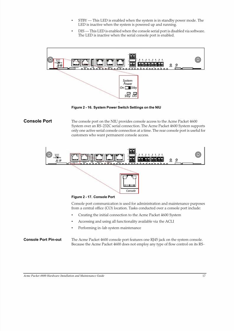
• STBY — This LED is enabled when the system is in standby power mode. TheLED is inactive when the system is powered up and running.
• DIS — This LED is enabled when the console serial port is disabled via software.The LED is inactive when the serial console port is enabled.
Figure 2 - 16. System Power Switch Settings on the NIU
Console Port The console port on the NIU provides console access to the Acme Packet 4600System over an RS-232C serial connection. The Acme Packet 4600 System supportsonly one active serial console connection at a time. The rear console port is useful forcustomers who want permanent console access.
Figure 2 - 17. Console Port
Console port communication is used for administration and maintenance purposesfrom a central office (CO) location. Tasks conducted over a console port include:
• Creating the initial connection to the Acme Packet 4600 System
• Accessing and using all functionality available via the ACLI
• Performing in-lab system maintenance
Console Port Pin-out The Acme Packet 4600 console port features one RJ45 jack on the system console.Because the Acme Packet 4600 does not employ any type of flow control on its RS-
8/15/2019 Installation guide for ACME 4600
http://slidepdf.com/reader/full/installation-guide-for-acme-4600 20/132
18 Acme Packet 4600 Hardware Installation and Maintenance Guide
232 ports, only the RX, TX, and GND pins are used. The following table identifies thepin assignments and signal names/descriptions for the console connector.
Table 2 - 1. Console Port Pin-Out
Pin Number Signal Name/Description
3 Receive Data (RX)
4 Ground (GND)
6 Transmit Data (TX)
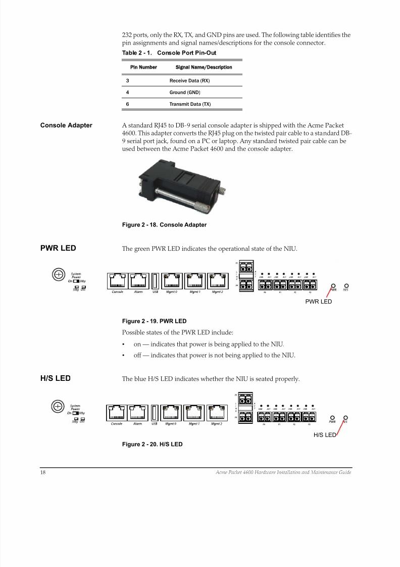
Console Adapter A standard RJ45 to DB-9 serial console adapter is shipped with the Acme Packet4600. This adapter converts the RJ45 plug on the twisted pair cable to a standard DB-9 serial port jack, found on a PC or laptop. Any standard twisted pair cable can beused between the Acme Packet 4600 and the console adapter.
Figure 2 - 18. Console Adapter
PWR LED The green PWR LED indicates the operational state of the NIU.
PWR LED
Figure 2 - 19. PWR LED
Possible states of the PWR LED include:
• on — indicates that power is being applied to the NIU.
• off — indicates that power is not being applied to the NIU.
H/S LED The blue H/S LED indicates whether the NIU is seated properly.
H/S LED
Figure 2 - 20. H/S LED
8/15/2019 Installation guide for ACME 4600
http://slidepdf.com/reader/full/installation-guide-for-acme-4600 21/132
Acme Packet 4600 Hardware Installation and Maintenance Guide 19
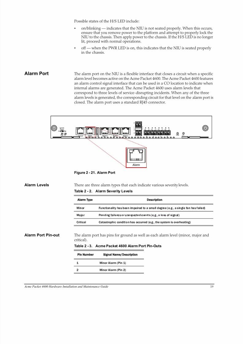
Possible states of the H/S LED include:
• on/blinking — indicates that the NIU is not seated properly. When this occurs,ensure that you remove power to the platform and attempt to properly lock theNIU to the chassis. Then apply power to the chassis. If the H/S LED is no longerlit, proceed with normal operations.
• off — when the PWR LED is on, this indicates that the NIU is seated properlyin the chassis.
Alarm Port The alarm port on the NIU is a flexible interface that closes a circuit when a specificalarm level becomes active on the Acme Packet 4600. The Acme Packet 4600 featuresan alarm control signal interface that can be used in a CO location to indicate wheninternal alarms are generated. The Acme Packet 4600 uses alarm levels thatcorrespond to three levels of service-disrupting incidents. When any of the threealarm levels is generated, the corresponding circuit for that level on the alarm port isclosed. The alarm port uses a standard RJ45 connector.
Figure 2 - 21. Alarm Port
Alarm Levels There are three alarm types that each indicate various severity
Table 2 - 2. Alarm Severity Levels
Alarm Type Description
Minor Functionality has been impaired to a small degree (e.g., a single fan has failed)
Major Pending fai lures or unexpected events (e.g., a loss of signal)
Critical Catastrophic condition has occurred (e.g., the system is overheating)
levels.
Alarm Port Pin-out The alarm port has pins for ground as well as each alarm level (minor, major and
critical).Table 2 - 3. Acme Packet 4600 Alarm Port Pin-Outs
Pin Number Signal Name/Description
1 Minor Alarm (Pin 1)
2 Minor Alarm (Pin 2)
8/15/2019 Installation guide for ACME 4600
http://slidepdf.com/reader/full/installation-guide-for-acme-4600 22/132
20 Acme Packet 4600 Hardware Installation and Maintenance Guide
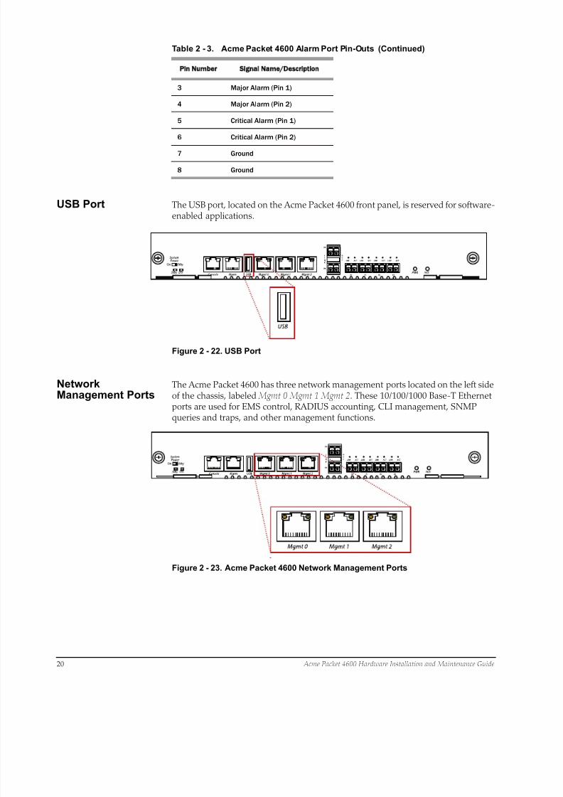
USB Port The USB port, located on the Acme Packet 4600 front panel, is reserved for software-enabled applications.
Figure 2 - 22. USB Port
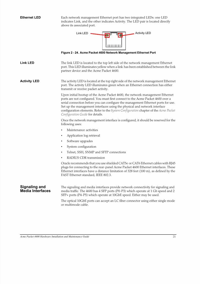
NetworkManagement Ports
The Acme Packet 4600 has three network management ports located on the left sideof the chassis, labeled Mgmt 0 Mgmt 1 Mgmt 2. These 10/100/1000 Base-T Ethernetports are used for EMS control, RADIUS accounting, CLI management, SNMP
queries and traps, and other management functions.
Figure 2 - 23. Acme Packet 4600 Network Management Ports
3 Major Alarm (Pin 1)
4 Major Alarm (Pin 2)
5 Critical Alarm (Pin 1)
6 Critical Alarm (Pin 2)
7 Ground
8 Ground
Table 2 - 3. Acme Packet 4600 Alarm Port Pin-Outs (Continued)
Pin Number Signal Name/Descript ion
8/15/2019 Installation guide for ACME 4600
http://slidepdf.com/reader/full/installation-guide-for-acme-4600 23/132
Acme Packet 4600 Hardware Installation and Maintenance Guide 21
Ethernet LED Each network management Ethernet port has two integrated LEDs: one LEDindicates Link, and the other indicates Activity. The LED pair is located directlyabove its associated port.
Link LED Activity LED
Figure 2 - 24. Acme Packet 4600 Network Management Ethernet Port
Link LED The link LED is located to the top left side of the network management Ethernetport. This LED illuminates yellow when a link has been established between the linkpartner device and the Acme Packet 4600.
Activity LED The activity LED is located at the top right side of the network management Ethernetport. The activity LED illuminates green when an Ethernet connection has eithertransmit or receive packet activity.
Upon initial bootup of the Acme Packet 4600, the network management Ethernet
ports are not configured. You must first connect to the Acme Packet 4600 over aserial connection before you can configure the management Ethernet ports for use.Set up the management interfaces using the physical and network interfaceconfiguration elements. Refer to the System Configuration chapter of the Acme PacketConfiguration Guide for details.
Once the network management interface is configured, it should be reserved for thefollowing uses:
• Maintenance activities
• Application log retrieval
• Software upgrades
• System configuration
• Telnet, SSH, SNMP and SFTP connections
• RADIUS CDR transmission
Oracle recommends that you use shielded CAT5e or CAT6 Ethernet cables with RJ45plugs for connecting to the rear-panel Acme Packet 4600 Ethernet interfaces. TheseEthernet interfaces have a distance limitation of 328 feet (100 m), as defined by theFAST Ethernet standard, IEEE 802.3.
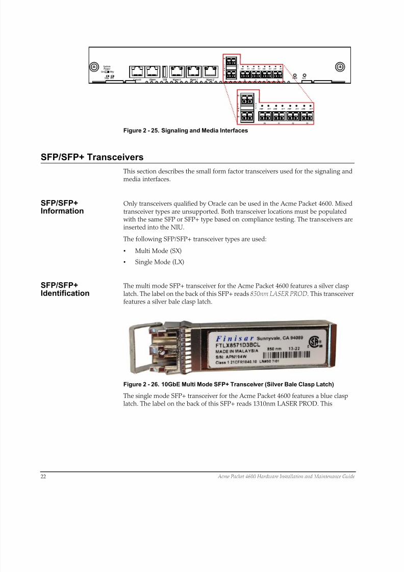
Signaling andMedia Interfaces
The signaling and media interfaces provide network connectivity for signaling andmedia traffic. The 4600 has 4 SFP ports (P0-P3) which operate at 1 Gb speed and 2SFP+ ports (P4-P5) which operate at 10GbE speed. Either may be used.
The optical 10GbE ports can accept an LC fiber connector using either single modeor multimode cable.
8/15/2019 Installation guide for ACME 4600
http://slidepdf.com/reader/full/installation-guide-for-acme-4600 24/132
22 Acme Packet 4600 Hardware Installation and Maintenance Guide
Figure 2 - 25. Signaling and Media Interfaces
SFP/SFP+ Transceivers
This section describes the small form factor transceivers used for the signaling andmedia interfaces.
SFP/SFP+Information
Only transceivers qualified by Oracle can be used in the Acme Packet 4600. Mixedtransceiver types are unsupported. Both transceiver locations must be populated with the same SFP or SFP+ type based on compliance testing. The transceivers areinserted into the NIU.
The following SFP/SFP+ transceiver types are used:
• Multi Mode (SX)
• Single Mode (LX)
SFP/SFP+Identification
The multi mode SFP+ transceiver for the Acme Packet 4600 features a silver clasplatch. The label on the back of this SFP+ reads 850nm LASER PROD. This transceiver
features a silver bale clasp latch.
Figure 2 - 26. 10GbE Multi Mode SFP+ Transceiver (Silver Bale Clasp Latch)
The single mode SFP+ transceiver for the Acme Packet 4600 features a blue clasplatch. The label on the back of this SFP+ reads 1310nm LASER PROD. This
8/15/2019 Installation guide for ACME 4600
http://slidepdf.com/reader/full/installation-guide-for-acme-4600 25/132
Acme Packet 4600 Hardware Installation and Maintenance Guide 23
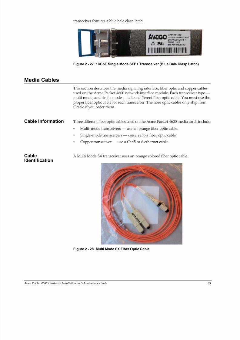
transceiver features a blue bale clasp latch.
Figure 2 - 27. 10GbE Single Mode SFP+ Transceiver (Blue Bale Clasp Latch)
Media Cables
This section describes the media signaling interface, fiber optic and copper cablesused on the Acme Packet 4600 network interface module. Each transceiver type —multi mode, and single mode — take a different fiber optic cable. You must use theproper fiber optic cable for each transceiver. The fiber optic cables only ship fromOracle if you order them.
Cable Information Three different fiber optic cables used on the Acme Packet 4600 media cards include:
• Multi-mode transceivers — use an orange fiber optic cable.
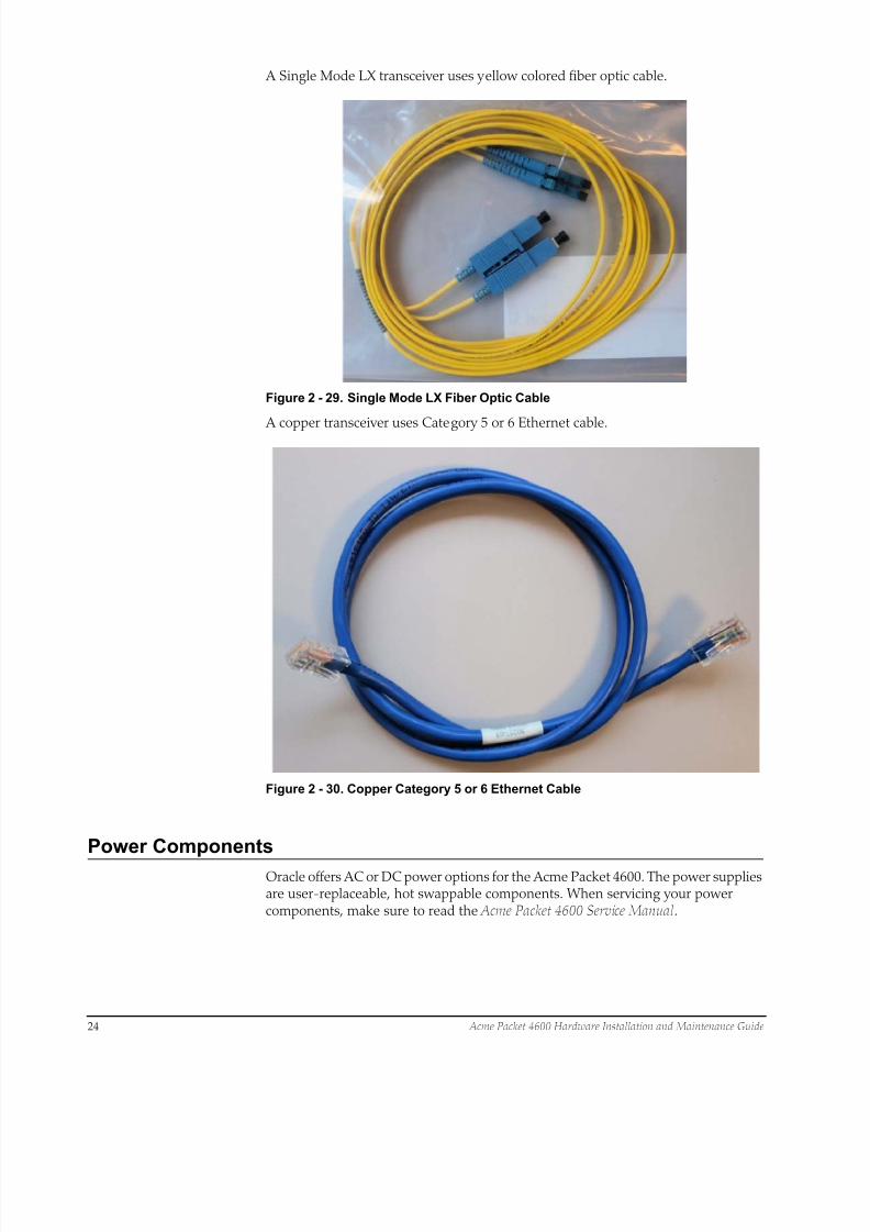
• Single-mode transceivers — use a yellow fiber optic cable.
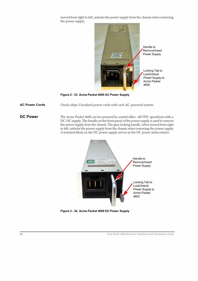
• Copper transceiver — use a Cat 5 or 6 ethernet cable.
CableIdentification
A Multi Mode SX transceiver uses an orange colored fiber optic cable.
Figure 2 - 28. Multi Mode SX Fiber Optic Cable
8/15/2019 Installation guide for ACME 4600
http://slidepdf.com/reader/full/installation-guide-for-acme-4600 26/132

8/15/2019 Installation guide for ACME 4600
http://slidepdf.com/reader/full/installation-guide-for-acme-4600 27/132
Acme Packet 4600 Hardware Installation and Maintenance Guide 25
Each power supply is accessed from the rear panel of the Acme Packet 4600. Thepower supply located at right is designated as power supply A while the powersupply located at left is designated as power supply B.
Power Supply B Power Supply AGrounding Terminals
Figure 2 - 31. Acme Packet 4600 Dual AC Power Supplies and Grounding Posts
Power Supply B Power Supply AGrounding Terminals
Figure 2 - 32. Acme Packet 4600 Dual DC Power Supplies and Grounding Posts
Power SupplyRedundancy
During normal operation, the Acme Packet 4600 is load-balanced and draws powerfrom both supplies. The two power supplies also provide hardware redundancy. If apower supply fails, the Acme Packet 4600 can rely on only one functional powersupply to sustain normal operation. A malfunctioning power supply must beremoved and replaced as soon as possible. If the Acme Packet 4600 starts up withonly one power supply, it will not generate an alarm.
AC Power The auto-sensing AC power supply is rated at 110-240 VAC, 50-60 Hz, and issupplied with an IEC connector. The handle on the front panel of the power supplyis used to remove the power supply from the chassis. The grey locking handle, when
8/15/2019 Installation guide for ACME 4600
http://slidepdf.com/reader/full/installation-guide-for-acme-4600 28/132
26 Acme Packet 4600 Hardware Installation and Maintenance Guide
moved from right to left, unlocks the power supply from the chassis when removingthe power supply.
Handle to
Remove/Insert
Power Supply
Locking Tab to
Lock/Unlock
Power Supply to
Acme Packet
4600
Figure 2 - 33. Acme Packet 4600 AC Power Supply
AC Power Cords Oracle ships 2 localized power cords with each AC-powered system.
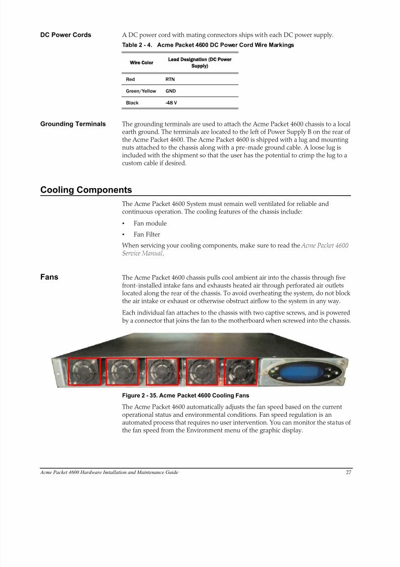
DC Power The Acme Packet 4600 can be powered by central office –48 VDC operations with aDC-DC supply. The handle on the front panel of the power supply is used to removethe power supply from the chassis. The grey locking handle, when moved from rightto left, unlocks the power supply from the chassis when removing the power supply A terminal block on the DC power supply serves as the DC power interconnect.
Handle to
Remove/Insert
Power Supply
Locking Tab to
Lock/Unlock
Power Supply to
Acme Packet
4600
Figure 2 - 34. Acme Packet 4600 DC Power Supply
8/15/2019 Installation guide for ACME 4600
http://slidepdf.com/reader/full/installation-guide-for-acme-4600 29/132
Acme Packet 4600 Hardware Installation and Maintenance Guide 27
DC Power Cords A DC power cord with mating connectors ships with each DC power supply.
Table 2 - 4. Acme Packet 4600 DC Power Cord Wire Markings
Wire Color
Lead Designation DC Power
Supply)
Red RTN
Green/Yellow GND
Black -48 V
Grounding Terminals The grounding terminals are used to attach the Acme Packet 4600 chassis to a localearth ground. The terminals are located to the left of Power Supply B on the rear ofthe Acme Packet 4600. The Acme Packet 4600 is shipped with a lug and mountingnuts attached to the chassis along with a pre-made ground cable. A loose lug isincluded with the shipment so that the user has the potential to crimp the lug to acustom cable if desired.
Cooling Components
The Acme Packet 4600 System must remain well ventilated for reliable andcontinuous operation. The cooling features of the chassis include:
• Fan module
• Fan Filter
When servicing your cooling components, make sure to read the Acme Packet 4600Service Manual.
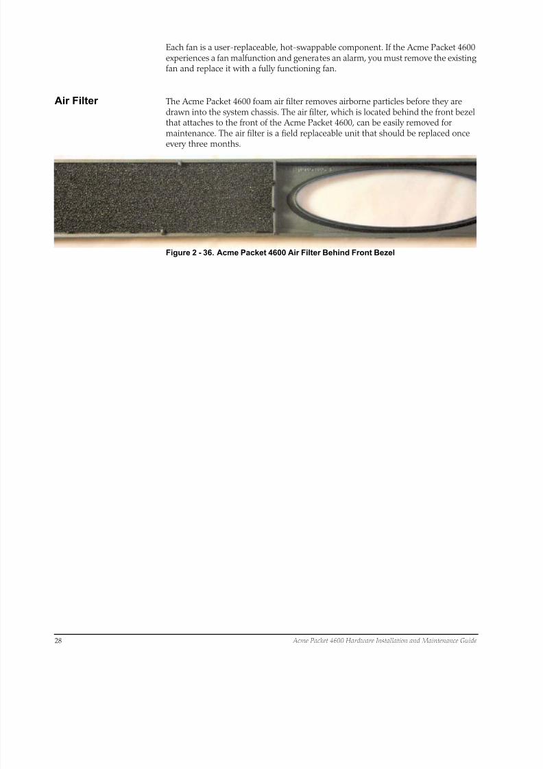
Fans The Acme Packet 4600 chassis pulls cool ambient air into the chassis through fivefront-installed intake fans and exhausts heated air through perforated air outletslocated along the rear of the chassis. To avoid overheating the system, do not blockthe air intake or exhaust or otherwise obstruct airflow to the system in any way.
Each individual fan attaches to the chassis with two captive screws, and is poweredby a connector that joins the fan to the motherboard when screwed into the chassis.
Figure 2 - 35. Acme Packet 4600 Cooling Fans
The Acme Packet 4600 automatically adjusts the fan speed based on the currentoperational status and environmental conditions. Fan speed regulation is anautomated process that requires no user intervention. You can monitor the status ofthe fan speed from the Environment menu of the graphic display.
8/15/2019 Installation guide for ACME 4600
http://slidepdf.com/reader/full/installation-guide-for-acme-4600 30/132

8/15/2019 Installation guide for ACME 4600
http://slidepdf.com/reader/full/installation-guide-for-acme-4600 31/132
Acme Packet 4600 Hardware Installation and Maintenance Guide 29
3 Graphic Display
Graphic DisplayThe four-line graphic display located on the Acme Packet 4600 front control panel is visible at all times. The buttons used to navigate the display are accessible as well.The graphic display reports real-time status, alarms, and general systeminformation. You can view this information without using a console, Telnet, or SSHconnection into the Acme Packet 4600.
Graphic DisplayNavigation
Three navigation buttons are located to the right of the display. These are used toscroll through display menus and select the information to view on the graphicdisplay
Alarm
Alarm
Power
Silence
Acme Packet
AP4600
Graphic Display Navigation Buttons Alarm Silence Button
Down Up Enter
Figure 3 - 37. Acme Packet 4600 Graphic Display and Control
Each graphic display button has a special purpose.
Table 3 - 5. Acme Packet 4600 Graphic Display Button Functions
Button Description
Up Scrolls up through the previous menu or display items, one line at a time.
Down Scrol ls down through the next menu or display items, one l ine at a t ime.
Enter Selects the menu or display item that appears in the graphic display window.

8/15/2019 Installation guide for ACME 4600
http://slidepdf.com/reader/full/installation-guide-for-acme-4600 32/132
30 Acme Packet 4600 Hardware Installation and Maintenance Guide
Display Modes
The Acme Packet 4600 graphic display defaults to one of two display modes:
• Base display is the default and indicates a properly-functioning Acme Packet4600.
• Alarm mode becomes the default display mode when any alarms are active onthe Acme Packet 4600. Active fault information is continuously displayed on thegraphic display.
Base Display The base display shows the type of Acme Packet 4600 running. This informationappears when the system first starts up and when the graphic display times out atany menu level.
ORACLE
AP4600
The base display of a Acme Packet 4600 in an HA node includes additionalinformation applicable to its HA state.
Alarm Display The alarm display replaces the base display during an alarm condition. The alarmdisplay informs you of what symptoms are currently causing alarms. The numberand type of alarms appear on the Acme Packet 4600 graphic display, which indicateseither a link alarm or a hardware alarm. For example, if there are two link alarmspresent on the Acme Packet 4600, the display appears like this:
2 LINK ALARMS
If the graphic display indicates an alarm condition, you can use the ACLI display-alarms command to display the details of the alarm. When an alarm condition iscleared, the base display replaces the alarm display. To clear an alarm, you mustexecute the ACLI clear-alarm command or resolve the cause of the alarm.
Graphic Display Menus
The Acme Packet 4600 System graphic display lets you access the five display menusfor quick access to the system’s current status.
Top Menu The top menu provides top-level access to information in distinct categories ofsystem functionality.
To access the top menu from the base display or alarm display:
1. Press the Enter button. The first entry in the top menu appears.2. Press the Up and Down buttons to scroll through the top menu categories. The
top menu rolls over when you reach the top or bottom of the menu.
The top menu displays only one category at a time. Press the Enter button toselect a displayed category and show its submenu information.
8/15/2019 Installation guide for ACME 4600
http://slidepdf.com/reader/full/installation-guide-for-acme-4600 33/132
Acme Packet 4600 Hardware Installation and Maintenance Guide 31
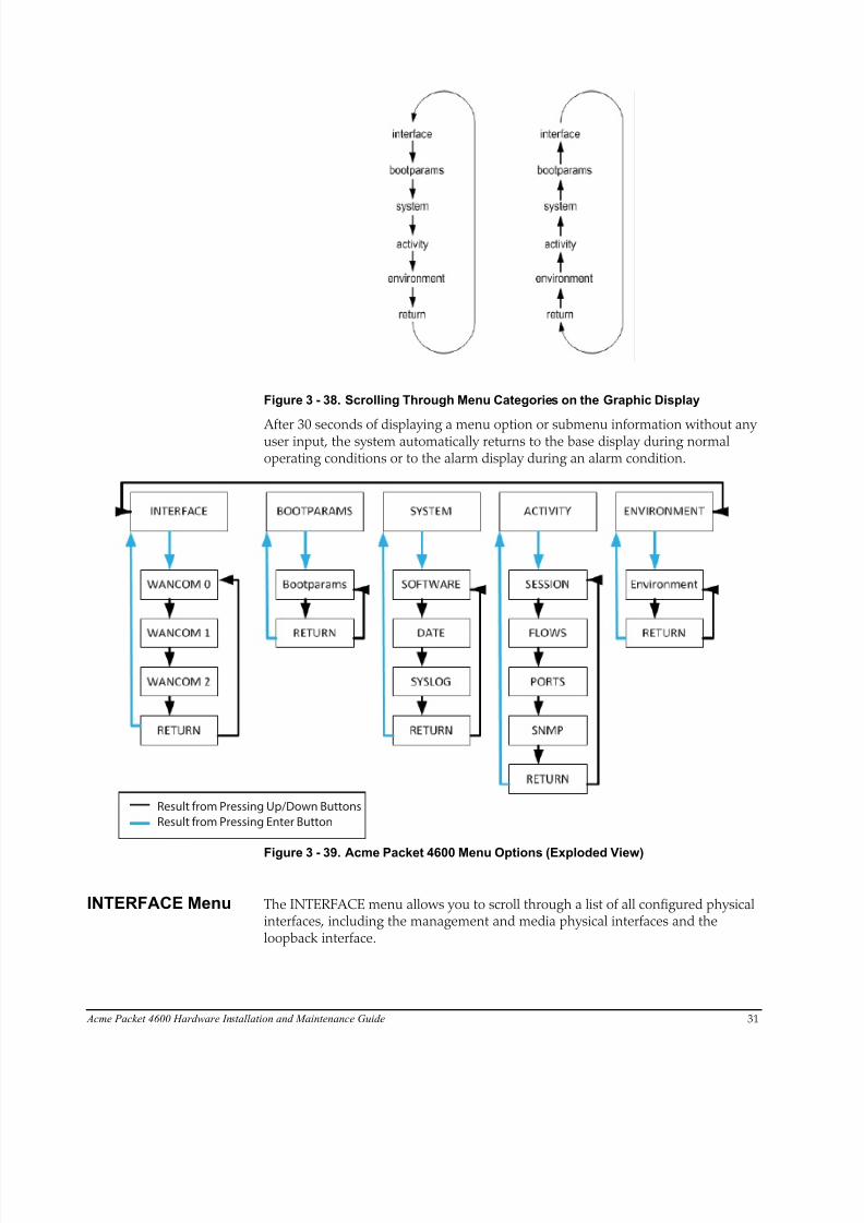
Figure 3 - 38. Scrolling Through Menu Categories on the Graphic Display
After 30 seconds of displaying a menu option or submenu information without anyuser input, the system automatically returns to the base display during normaloperating conditions or to the alarm display during an alarm condition.
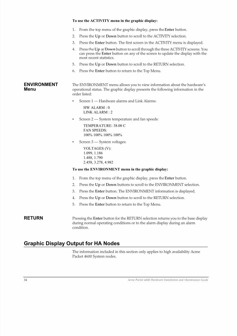
Result from Pressing Up/Down Buttons
Result from Pressing Enter Button
Figure 3 - 39. Acme Packet 4600 Menu Options (Exploded View)
INTERFACE Menu The INTERFACE menu allows you to scroll through a list of all configured physicalinterfaces, including the management and media physical interfaces and theloopback interface.

8/15/2019 Installation guide for ACME 4600
http://slidepdf.com/reader/full/installation-guide-for-acme-4600 34/132
32 Acme Packet 4600 Hardware Installation and Maintenance Guide
The following information is displayed for each configured interface to which youscroll:
• Interface slot and port: interface status
• Input packets, output packets
• Input error packets, output error packets
Slot 1: Port0 UP
PKT IN: 1,001K OUT: 223K
ERR IN: 0 OUT: 0
To use the INTERFACE menu in the graphic display:
1. From the top menu of the graphic display, press the Enter button.
2. Press the Up or Down button to scroll to the INTERFACE selection.
3. Press the Enter button.
4. Press the Up or Down button to scroll through the list of configured physicalinterfaces.
5. Press the Enter button to refresh the display.
6. Press the Up or Down button to scroll to the RETURN selection.
7. Press the Enter button to return to the Top Menu.
BOOT PARAMSMenu
The BOOT PARAMS menu allows you to view the same information configured inthe bootparam ACLI configuration. The BOOT PARAMS selection displays the IPinformation necessary to connect to the Mgmt 0 Ethernet interface, located on therear of the Acme Packet 4600. This interface is used primarily for maintenance,configuration, and downloading software images.
The following information for Mgmt 0 is displayed under the BOOT PARAMS menu:
• IP address
• Netmask in hexadecimal format
• Gateway IP address
inet: 192.168.0.2
mask: ffff0000
gw: 192.168.0.1
To use the BOOT PARAMS menu in the graphic display:
1. From the top menu of the graphic display, press the Enter button.
2. Press the Up or Down button to scroll to the BOOT PARAMS selection.
3. Press the Enter button. The BOOT PARAMS information is displayed.
4. Press the Up or Down button to scroll to the RETURN selection.
5. Press the Enter button to return to the Top Menu.
SYSTEM Menu The SYSTEM menu allows you to view system software, current time, and sysloginformation. The following information displays over three screens in the graphicdisplay in the order listed:

8/15/2019 Installation guide for ACME 4600
http://slidepdf.com/reader/full/installation-guide-for-acme-4600 35/132
Acme Packet 4600 Hardware Installation and Maintenance Guide 33
• Screen 1 — Acme Packet 4600 software version and creation date:
Software:
ACME OS 7.2.0
03/01/2014
• Screen 2 — Current time of day, uptime, memory utilization:
Time 18:33:21
UPTIME 10, 10:23:20
MEMORY 65%
• Screen 3 — Syslog information (IP address:port of the syslog server and thenetmask in dotted decimal notation):
Syslog:
192.168.121.12:514
255.255.255.0
To use the SYSTEM menu in the graphic display:
1. From the top menu of the graphic display, press the Enter button.
2. Press the Up or Down button to scroll to the SYSTEM selection.
3. Press the Enter button. The first screen in the SYSTEM menu is displayed.
4. Press the Up or Down button to scroll through the three SYSTEM screens. Youcan press the Enter button on the Time screen to update its display.
5. Press the Up or Down button to scroll to the RETURN selection.
6. Press the Enter button to return to the Top Menu.
ACTIVITY Menu The ACTIVITY menu allows you to scroll through current Acme Packet 4600 trafficstatistics. These statistics provide a real-time snapshot of the capacity at which thesystem is operating.
The following information is displayed on the Acme Packet 4600 ACTIVITY displayin the order listed:
• Screen 1 — Number of sessions, sessions per minute, sessions per hour:
200 Sessions
40 Sessions/Minute
180 Sessions/Hour
• Screen 2 — Number of flows, flows per minute, flows per hour:
400 Flows
80 Flows/Minute
360 Flows/Hour
• Screen 3 — Number of used ports, number of free ports:
1000 Used Ports
2000 Free Ports
• Screen 4 — SNMP information: number of SNMP packets received, number ofSNMP traps sent out:
SNMP:
PKTs in :20
TRAPs out :10
8/15/2019 Installation guide for ACME 4600
http://slidepdf.com/reader/full/installation-guide-for-acme-4600 36/132
34 Acme Packet 4600 Hardware Installation and Maintenance Guide
To use the ACTIVITY menu in the graphic display:
1. From the top menu of the graphic display, press the Enter button.
2. Press the Up or Down button to scroll to the ACTIVITY selection.
3. Press the Enter button. The first screen in the ACTIVITY menu is displayed.
4. Press the Up or Down button to scroll through the three ACTIVITY screens. Youcan press the Enter button on any of the screen to update the display with the
most recent statistics.5. Press the Up or Down button to scroll to the RETURN selection.
6. Press the Enter button to return to the Top Menu.
ENVIRONMENTMenu
The ENVIRONMENT menu allows you to view information about the hardware’soperational status. The graphic display presents the following information in theorder listed:
• Screen 1 — Hardware alarms and Link Alarms:
HW ALARM : 0
LINK ALARM : 2
• Screen 2 — System temperature and fan speeds:
TEMPERATURE: 38.00 C
FAN SPEEDS:
100% 100% 100% 100%
• Screen 3 — System voltages:
VOLTAGES (V):
1.099, 1.186
1.488, 1.790
2.458, 3.278, 4.982
To use the ENVIRONMENT menu in the graphic display:
1. From the top menu of the graphic display, press the Enter button.
2. Press the Up or Down buttons to scroll to the ENVIRONMENT selection.
3. Press the Enter button. The ENVIRONMENT information is displayed.
4. Press the Up or Down button to scroll to the RETURN selection.
5. Press the Enter button to return to the Top Menu.
RETURN Pressing the Enter button for the RETURN selection returns you to the base displayduring normal operating conditions or to the alarm display during an alarmcondition.
Graphic Display Output for HA Nodes
The information included in this section only applies to high availability AcmePacket 4600 System nodes.
8/15/2019 Installation guide for ACME 4600
http://slidepdf.com/reader/full/installation-guide-for-acme-4600 37/132
Acme Packet 4600 Hardware Installation and Maintenance Guide 35
The graphic display on a Acme Packet 4600 in an HA node indicates the current HAstate. Five state indications can be displayed on the graphic display. Only theStandby and Active state indications appear in the graphic display for more than afew seconds. An explanation and example of each HA state follows.
Initial State Displays The following example shows the output in the graphic display window of a AcmePacket 4600 in the initial state:
NET - NETSESSION DIRECTOR (I)
Out-Of-Service StateDisplays
The following example shows the output in the graphic display window of an out-of-service Acme Packet 4600:
NET - NET
SESSION DIRECTOR (O/S)
Becoming StandbyState Displays
The following example shows the output in the graphic display window of abecoming standby Acme Packet 4600:
NET - NET
SESSION DIRECTOR (B/S)
Standby StateDisplays
The following example shows the output in the graphic display window of a standby Acme Packet 4600:
NET - NET
SESSION DIRECTOR (S)
Active State Displays Acme Packet 4600 Systems in the active state use the default graphic display. Thefollowing example shows the display of an active Acme Packet 4600:
NET - NET
SESSION DIRECTOR

8/15/2019 Installation guide for ACME 4600
http://slidepdf.com/reader/full/installation-guide-for-acme-4600 38/132
36 Acme Packet 4600 Hardware Installation and Maintenance Guide
8/15/2019 Installation guide for ACME 4600
http://slidepdf.com/reader/full/installation-guide-for-acme-4600 39/132
Acme Packet 4600 Hardware Installation and Maintenance Guide 37
4 System Installation
IntroductionThis chapter provides information about how to install the Acme Packet 4600System and its associated components, includes cabling information.
Shipped Parts
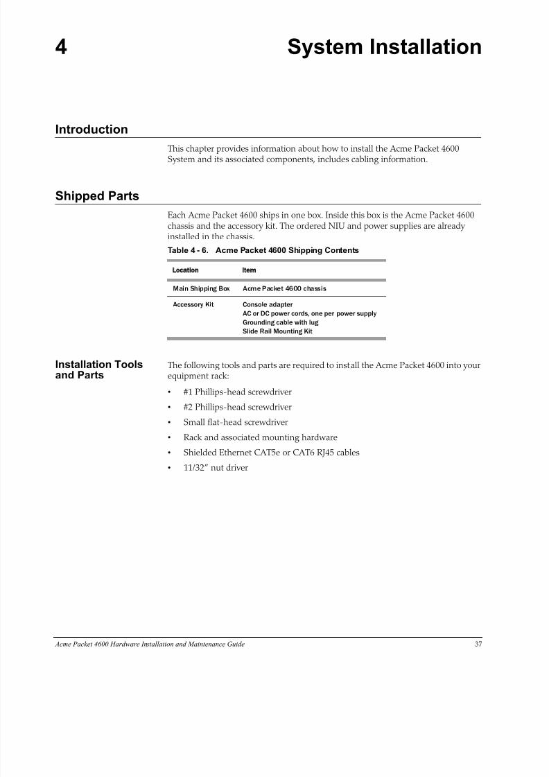
Each Acme Packet 4600 ships in one box. Inside this box is the Acme Packet 4600chassis and the accessory kit. The ordered NIU and power supplies are alreadyinstalled in the chassis.
Table 4 - 6. Acme Packet 4600 Shipping Contents
Location Item
Main Shipping Box Acme Packet 4600 chassis
Accessory Kit Console adapter
AC or DC power cords, one per power supply
Grounding cable with lug
Slide Rail Mounting Kit
Installation Toolsand Parts
The following tools and parts are required to install the Acme Packet 4600 into yourequipment rack:
• #1 Phillips-head screwdriver
• #2 Phillips-head screwdriver• Small flat-head screwdriver
• Rack and associated mounting hardware
• Shielded Ethernet CAT5e or CAT6 RJ45 cables
• 11/32” nut driver
8/15/2019 Installation guide for ACME 4600
http://slidepdf.com/reader/full/installation-guide-for-acme-4600 40/132
38 Acme Packet 4600 Hardware Installation and Maintenance Guide
RecommendedTools and Parts
Acme Packet recommends that you have the following parts on hand:
• Cable labels
• UPS for AC installations
• ESD wrist or heel straps
• ESD-safe location
Pre-Installation Guidelines
The Acme Packet 4600 must have access to reliable power and cooling. Whenchoosing a location for your Acme Packet 4600, follow the guidelines listed in thissection.
EnvironmentalGuidelines
When preparing to install your Acme Packet 4600:
• Ensure that the equipment rack location complies with the environmentalspecifications (e.g., temperature, relative humidity, and maximum altitude) ofthe Acme Packet 4600 described in the chapter on Specifications.
• Locate the Acme Packet 4600 in a clean and well-ventilated room. This locationshould also be far from areas where heat, electrical noise, and electromagneticfields are present.
Power Guidelines When preparing to install your Acme Packet 4600, please ensure you do thefollowing:
• Ensure that the installation location has access to adequate power andgrounding. Separate circuits should be available for each of the Acme Packet4600 two power supplies.
• The Acme Packet 4600 may only be powered by AC or DC circuits at one time;mixed power configurations are unsupported.
• Never use extension cords when powering a Acme Packet 4600.
• Use grounded, 3-conductor circuits.
• A local earth ground must be available.
Caution Connect each of the Acme Packet 4600 power supplies to a
separate circuit. If both supplies are connected to outlets on
the same circuit the Acme Packet 4600 will lose power to
both supplies if that circuit loses power. In that case the whole
Acme Packet 4600 would lose power.
8/15/2019 Installation guide for ACME 4600
http://slidepdf.com/reader/full/installation-guide-for-acme-4600 41/132
Acme Packet 4600 Hardware Installation and Maintenance Guide 39
MountingGuidelines
When preparing to install your Acme Packet 4600, please ensure you follow thesemounting guidelines:
• Leave enough clearance, approximately 8” (20 cm), behind the equipment rackto allow adequate air ventilation, for ease in cabling, and to access the consoleconnector, reset button, graphic display buttons, and physical interface cardslots.
• Do not block the air inlets or the fan module, or obstruct airflow to the systemin any way.
• Position the equipment to allow for serviceability. This will aid in chassisremoval, and prevent the need to remove or loosen other equipment in the rack.
• Remember that the Ethernet interfaces are limited to 328 feet/100 meters asdefined by the FAST Ethernet standard, IEEE 802.3.
Other SafetyGuidelines
When preparing to install your Acme Packet 4600, ensure you follow these safetyguidelines:
• Review all safety precautions with respect to the Acme Packet 4600 beforebeginning installation.
• Ensure that the equipment rack is securely bolted to the floor and that the
equipment rack and components are properly grounded.
• For AC power installations, use a regulating UPS to protect the Acme Packet4600 from power surges, voltage spikes, and power failures.
• For AC power installations, ensure that your UPS can supply power for enoughtime to save your system data and shut down the system gracefully.
Mounting Installation
Overview This section explains how to unpack and install your Acme Packet 4600 into atelecommunications or server equipment rack. The Acme Packet 4600 standardmounting hardware is used for installation in a 4-post, 19” cabinet-style equipmentrack. Mounting hardware for a 23” equipment rack is available by special order.
Mounting Options The Acme Packet 4600 ships with hardware for mounting in a 4-post, tapped-holeequipment rack or square-hole equipment rack. The Acme Packet 4600 also ships with hardware for mounting in a 2-post, center-mount equipment rack. This sectionexplains the procedures for each mounting option.
Caution Failure to follow the instructions outlined in this section might
compromise the proper function of the Acme Packet 4600. To
prevent personal injury Acme Packet recommends that two
people lift and install the chassis into the equipment rack.
8/15/2019 Installation guide for ACME 4600
http://slidepdf.com/reader/full/installation-guide-for-acme-4600 42/132
40 Acme Packet 4600 Hardware Installation and Maintenance Guide
Unpacking the AcmePacket 4600
To unpack the Acme Packet 4600:
1. Inspect the external packing materials and note if they are damaged in any way.
2. Open the exterior box.
3. Unpack the contents of the Acme Packet 4600 shipment.
4. Locate the packing list on the outside of the Acme Packet 4600 shipment box.
5. Confirm that all of the components listed in the packing list are present and ingood condition.
If you discover that any of the parts are missing or were damaged inshipment, contact customer support.
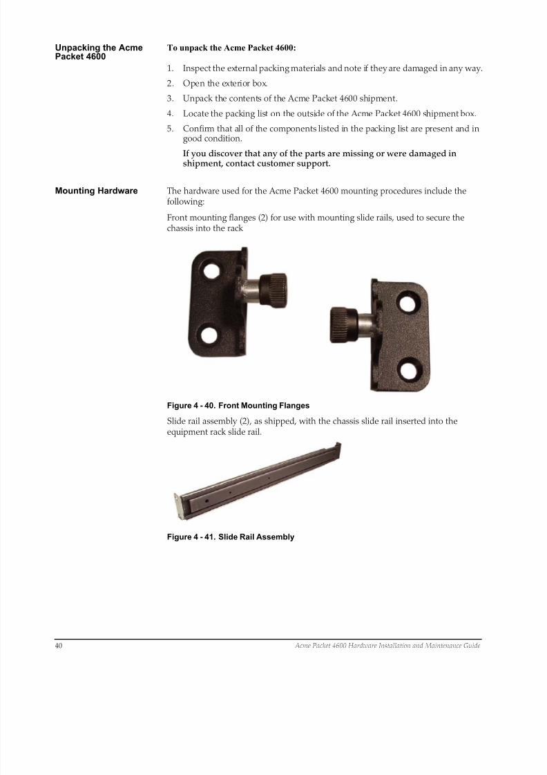
Mounting Hardware The hardware used for the Acme Packet 4600 mounting procedures include thefollowing:
Front mounting flanges (2) for use with mounting slide rails, used to secure thechassis into the rack
Figure 4 - 40. Front Mounting Flanges
Slide rail assembly (2), as shipped, with the chassis slide rail inserted into theequipment rack slide rail.
Figure 4 - 41. Slide Rail Assembly

8/15/2019 Installation guide for ACME 4600
http://slidepdf.com/reader/full/installation-guide-for-acme-4600 43/132
Acme Packet 4600 Hardware Installation and Maintenance Guide 41
• Equipment rack slide rail (part of the slide rail assembly)
Figure 4 - 42. Equipment Rack Slide Rail
• Chassis slide rail (part of the slide rail assembly)
Figure 4 - 43. Chassis Slide Rail
• Nut Bar (4)
Figure 4 - 44. Nut Bar
• Mounting Spacer (2)
Figure 4 - 45. Mounting Spacer
8/15/2019 Installation guide for ACME 4600
http://slidepdf.com/reader/full/installation-guide-for-acme-4600 44/132
42 Acme Packet 4600 Hardware Installation and Maintenance Guide
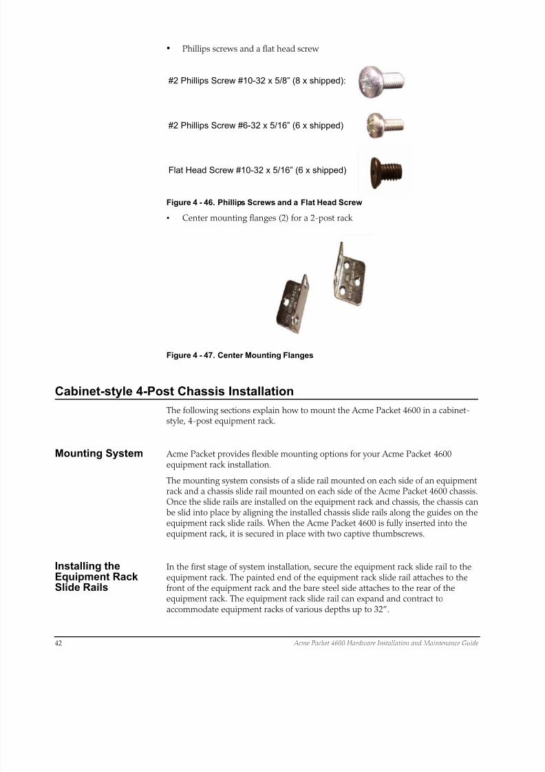
•
#2 Phillips Screw #10-32 x 5/8” (8 x shipped):
#2 Phillips Screw #6-32 x 5/16” (6 x shipped)
Flat Head Screw #10-32 x 5/16” (6 x shipped)
Phillips screws and a flat head screw
Figure 4 - 46. Phillips Screws and a Flat Head Screw
• Center mounting flanges (2) for a 2-post rack
Figure 4 - 47. Center Mounting Flanges
Cabinet-style 4-Post Chassis Installation
The following sections explain how to mount the Acme Packet 4600 in a cabinet-style, 4-post equipment rack.
Mounting System Acme Packet provides flexible mounting options for your Acme Packet 4600equipment rack installation.
The mounting system consists of a slide rail mounted on each side of an equipmentrack and a chassis slide rail mounted on each side of the Acme Packet 4600 chassis.Once the slide rails are installed on the equipment rack and chassis, the chassis canbe slid into place by aligning the installed chassis slide rails along the guides on theequipment rack slide rails. When the Acme Packet 4600 is fully inserted into theequipment rack, it is secured in place with two captive thumbscrews.
Installing theEquipment RackSlide Rails
In the first stage of system installation, secure the equipment rack slide rail to theequipment rack. The painted end of the equipment rack slide rail attaches to thefront of the equipment rack and the bare steel side attaches to the rear of theequipment rack. The equipment rack slide rail can expand and contract toaccommodate equipment racks of various depths up to 32”.
8/15/2019 Installation guide for ACME 4600
http://slidepdf.com/reader/full/installation-guide-for-acme-4600 45/132
Acme Packet 4600 Hardware Installation and Maintenance Guide 43
You can mount the equipment rack slide rail to both tapped hole rack and squarerack. Follow the appropriate procedure below.
Installing Slide Railsinto a Tapped-HoleRack
This section explains how to mount the Acme Packet 4600 slide rail assembly into atapped-hole equipment rack.
Note: The following procedure presumes that the tapped hole size
is #10-32. If alternate tapped holes are used, the customer mustsupply the proper screws.
To install the slide rails to the front of a tapped-hole equipment rack:
1. Locate the following components:
• Assembled equipment rack slide rails (2)
• #10-32 x 5/8” screws (8)
• Mounting spacers (2)
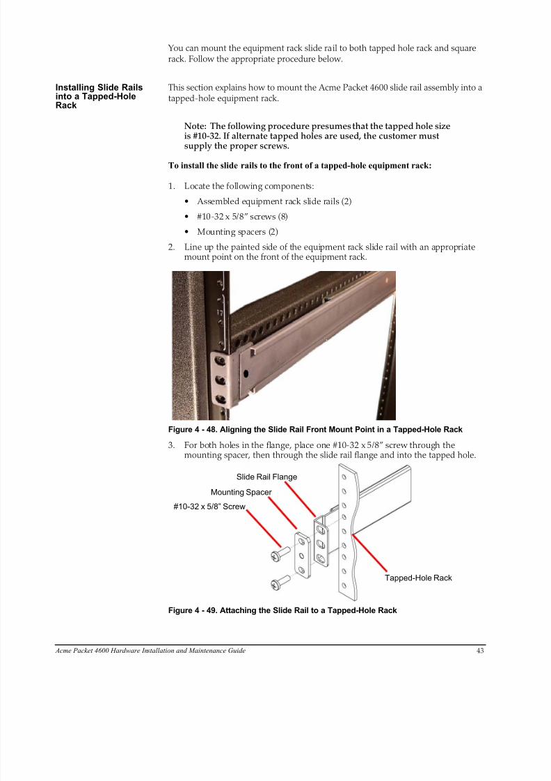
2. Line up the painted side of the equipment rack slide rail with an appropriatemount point on the front of the equipment rack.
Figure 4 - 48. Aligning the Slide Rail Front Mount Point in a Tapped-Hole Rack
3. For both holes in the flange, place one #10-32 x 5/8” screw through themounting spacer, then through the slide rail flange and into the tapped hole.
Mounting Spacer
#10-32 x 5/8” Screw
Slide Rail Flange
Tapped-Hole Rack
Figure 4 - 49. Attaching the Slide Rail to a Tapped-Hole Rack

8/15/2019 Installation guide for ACME 4600
http://slidepdf.com/reader/full/installation-guide-for-acme-4600 46/132
44 Acme Packet 4600 Hardware Installation and Maintenance Guide
4. Using a #2 Phillips head screwdriver, tighten the screws to secure the slide railto the equipment rack. Do not completely torque the screws; leave a smallamount of play at this time.
Figure 4 - 50. Installed Slide Rail in a Tapped-Hole Rack - Front Mount Point
5. Expand and line up the unpainted side of the equipment rack slide rail on theoutside of the rear rack slide rail at the same height used for the front mountpoint.
Figure 4 - 51. Aligning Rear Mount Points of the Slide Rail in a Tapped-Hole Rack
6. For both holes in the slide rail flange, place one #10-32 x 5/8” screw through theflange and into the tapped hole, and screw them into place.
Figure 4 - 52. Installed Slide Rail in a Tapped-Hole Rack - Rear Mount Point
8/15/2019 Installation guide for ACME 4600
http://slidepdf.com/reader/full/installation-guide-for-acme-4600 47/132
Acme Packet 4600 Hardware Installation and Maintenance Guide 45
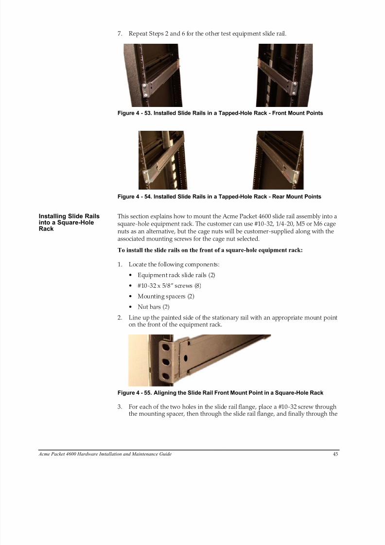
7. Repeat Steps 2 and 6 for the other test equipment slide rail.
Figure 4 - 53. Installed Slide Rails in a Tapped-Hole Rack - Front Mount Points
Figure 4 - 54. Installed Slide Rails in a Tapped-Hole Rack - Rear Mount Points
Installing Slide Railsinto a Square-HoleRack
This section explains how to mount the Acme Packet 4600 slide rail assembly into asquare-hole equipment rack. The customer can use #10-32, 1/4-20, M5 or M6 cagenuts as an alternative, but the cage nuts will be customer-supplied along with theassociated mounting screws for the cage nut selected.
To install the slide rails on the front of a square-hole equipment rack:
1. Locate the following components:
• Equipment rack slide rails (2)
• #10-32 x 5/8” screws (8)• Mounting spacers (2)
• Nut bars (2)
2. Line up the painted side of the stationary rail with an appropriate mount pointon the front of the equipment rack.
Figure 4 - 55. Aligning the Slide Rail Front Mount Point in a Square-Hole Rack
3. For each of the two holes in the slide rail flange, place a #10-32 screw throughthe mounting spacer, then through the slide rail flange, and finally through the

8/15/2019 Installation guide for ACME 4600
http://slidepdf.com/reader/full/installation-guide-for-acme-4600 48/132
46 Acme Packet 4600 Hardware Installation and Maintenance Guide
square hole in the rack rail.
Mounting Spacer
#10-32x5/8” Screw
Slide Rail Flange
Nut Bar
Square-Hole Rack
Figure 4 - 56. Attaching the Slide Rail to a Square-Hole Rack
4. Hold the nut bar behind the front rack rail.
5. Using a #2 Phillips head screwdriver, tighten the screws to secure the slide railto the equipment rack. Do not completely torque the screws; leave a smallamount of play at this time.
Figure 4 - 57. Installed Slide Rail in a Square-Hole Rack - Front Mount Point
6. Expand and line up the unpainted side of the stationary rail flange on the outsideof the rear rack rail at the height used for the front mount point.
Figure 4 - 58. Aligning the Slide Rail Rear Mount Point in a Square-Hole Rack
7. Hold the nut bar behind the rear rack slide rail.
8. Place one #10-32 screw through each of the holes in the slide rail flange, thenthrough the square hole in the rack, and finally into the nut bar.
8/15/2019 Installation guide for ACME 4600
http://slidepdf.com/reader/full/installation-guide-for-acme-4600 49/132
Acme Packet 4600 Hardware Installation and Maintenance Guide 47
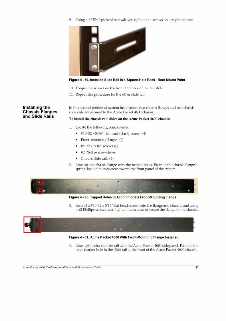
9. Using a #2 Phillips head screwdriver, tighten the screws securely into place.
Figure 4 - 59. Installed Slide Rail in a Square-Hole Rack - Rear Mount Point
10. Torque the screws on the front and back of the rail slide.
11. Repeat this procedure for the other slide rail.
Installing the
Chassis Flangesand Slide Rails
In this second portion of system installation, two chassis flanges and two chassis
slide rails are secured to the Acme Packet 4600 chassis.
To install the chassis rail slides on the Acme Packet 4600 chassis:
1. Locate the following components:
• #10-32 x 5/16” flat head (black) screws (4)
• Front-mounting flanges (2)
• #6-32 x 5/16” screws (6)
• #2 Phillips screwdriver
• Chassis slide rails (2)
2. Line up one chassis flange with the tapped holes. Position the chassis flange’s
spring-loaded thumbscrew toward the front panel of the system.
Figure 4 - 60. Tapped Holes to Accommodate Front-Mounting Flange
3. Insert 2 x #10-32 x 5/16” flat head screws into the flange and chassis, and usinga #2 Phillips screwdriver, tighten the screws to secure the flange to the chassis.
Figure 4 - 61. Acme Packet 4600 With Front-Mounting Flange Installed
4. Line up the chassis slide rail with the Acme Packet 4600 side panel. Position thelarge marker hole in the slide rail at the front of the Acme Packet 4600 chassis.
8/15/2019 Installation guide for ACME 4600
http://slidepdf.com/reader/full/installation-guide-for-acme-4600 50/132
48 Acme Packet 4600 Hardware Installation and Maintenance Guide
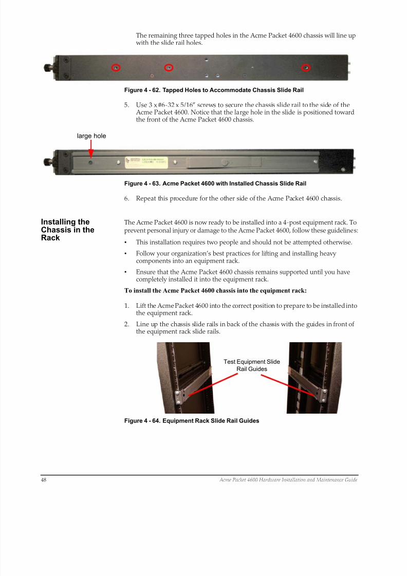
The remaining three tapped holes in the Acme Packet 4600 chassis will line up with the slide rail holes.
Figure 4 - 62. Tapped Holes to Accommodate Chassis Slide Rail
5. Use 3 x #6-32 x 5/16” screws to secure the chassis slide rail to the side of the Acme Packet 4600. Notice that the large hole in the slide is positioned towardthe front of the Acme Packet 4600 chassis.
large hole
Figure 4 - 63. Acme Packet 4600 with Installed Chassis Slide Rail
6. Repeat this procedure for the other side of the Acme Packet 4600 chassis.
Installing theChassis in theRack
The Acme Packet 4600 is now ready to be installed into a 4-post equipment rack. Toprevent personal injury or damage to the Acme Packet 4600, follow these guidelines:
• This installation requires two people and should not be attempted otherwise.
• Follow your organization’s best practices for lifting and installing heavycomponents into an equipment rack.
• Ensure that the Acme Packet 4600 chassis remains supported until you havecompletely installed it into the equipment rack.
To install the Acme Packet 4600 chassis into the equipment rack:
1. Lift the Acme Packet 4600 into the correct position to prepare to be installed intothe equipment rack.
2. Line up the chassis slide rails in back of the chassis with the guides in front ofthe equipment rack slide rails.
Test Equipment Slide
Rail Guides
Figure 4 - 64. Equipment Rack Slide Rail Guides
8/15/2019 Installation guide for ACME 4600
http://slidepdf.com/reader/full/installation-guide-for-acme-4600 51/132
Acme Packet 4600 Hardware Installation and Maintenance Guide 49
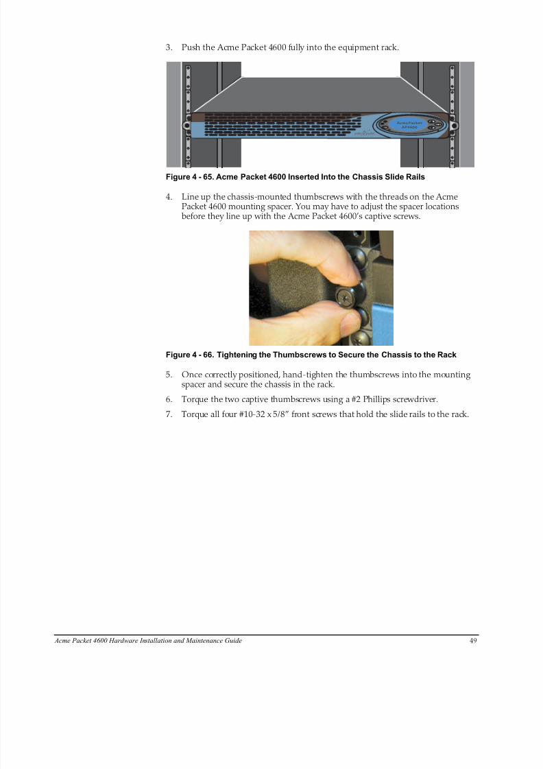
3. Push the Acme Packet 4600 fully into the equipment rack.
Alarm
Alarm
Power
Silence
Acme Packet
NN4600Alarm
Alarm
Power
Silence
Acme Packet
AP4600
Figure 4 - 65. Acme Packet 4600 Inserted Into the Chassis Slide Rails
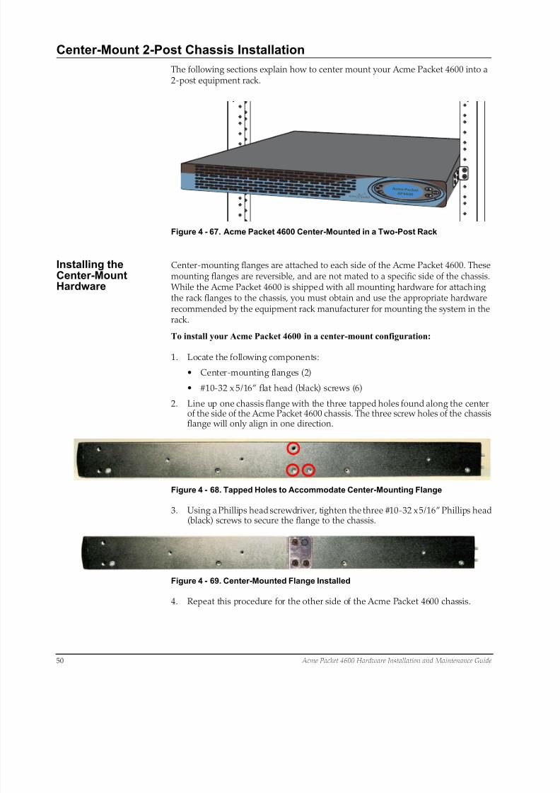
4. Line up the chassis-mounted thumbscrews with the threads on the AcmePacket 4600 mounting spacer. You may have to adjust the spacer locationsbefore they line up with the Acme Packet 4600’s captive screws.
Figure 4 - 66. Tightening the Thumbscrews to Secure the Chassis to the Rack
5. Once correctly positioned, hand-tighten the thumbscrews into the mountingspacer and secure the chassis in the rack.
6. Torque the two captive thumbscrews using a #2 Phillips screwdriver.7. Torque all four #10-32 x 5/8” front screws that hold the slide rails to the rack.
8/15/2019 Installation guide for ACME 4600
http://slidepdf.com/reader/full/installation-guide-for-acme-4600 52/132
50 Acme Packet 4600 Hardware Installation and Maintenance Guide
Center-Mount 2-Post Chassis Installation
The following sections explain how to center mount your Acme Packet 4600 into a2-post equipment rack.
Alarm
Alarm
Power
Silence
Acme Pack etAP4600
Figure 4 - 67. Acme Packet 4600 Center-Mounted in a Two-Post Rack
Installing the
Center-MountHardware
Center-mounting flanges are attached to each side of the Acme Packet 4600. These
mounting flanges are reversible, and are not mated to a specific side of the chassis. While the Acme Packet 4600 is shipped with all mounting hardware for attachingthe rack flanges to the chassis, you must obtain and use the appropriate hardwarerecommended by the equipment rack manufacturer for mounting the system in therack.
To install your Acme Packet 4600 in a center-mount configuration:
1. Locate the following components:
• Center-mounting flanges (2)
• #10-32 x 5/16” flat head (black) screws (6)
2. Line up one chassis flange with the three tapped holes found along the center
of the side of the Acme Packet 4600 chassis. The three screw holes of the chassisflange will only align in one direction.
Figure 4 - 68. Tapped Holes to Accommodate Center-Mounting Flange
3. Using a Phillips head screwdriver, tighten the three #10-32 x 5/16” Phillips head(black) screws to secure the flange to the chassis.
Figure 4 - 69. Center-Mounted Flange Installed
4. Repeat this procedure for the other side of the Acme Packet 4600 chassis.

8/15/2019 Installation guide for ACME 4600
http://slidepdf.com/reader/full/installation-guide-for-acme-4600 53/132
Acme Packet 4600 Hardware Installation and Maintenance Guide 51
Installing the Chassisin the Rack
The Acme Packet 4600 chassis is now ready to be installed into a 2-post equipmentrack. To prevent personal injury or damage to the Acme Packet 4600 follow theseguidelines:
• This installation requires two people and should not be attempted otherwise.
• Follow your organization’s best practices for lifting and installing heavycomponents into an equipment rack.
• Ensure that the Acme Packet 4600 chassis remains supported until you have
completely installed it into the equipment rack.
1. Locate the following components:
• Equipment rack screws (4)
2. Lift the Acme Packet 4600 into the correct position in the equipment rack.
3. Use a #2 Phillips screwdriver to secure two screws through the mounting flangeson the Acme Packet 4600 and into the equipment rack. One person should holdthe Acme Packet 4600 in the correct position while the other person screws the Acme Packet 4600 in place.
Alarm
Alarm
Power
Silence
Acme Pack etAP4600
Figure 4 - 70. Attaching the Acme Packet 4600 to a 2-Post Equipment Rack
4. Ensure that the Acme Packet 4600 chassis remains supported until you havecompletely installed it into the equipment rack.
Fan Module Installation
The fan module is pre-installed in the Acme Packet 4600 chassis when it ships. Thereis no need to remove the fan module prior to installation. In the event that this partneeds service or replacement, you can remove and replace it with a functioning one.For more information, see “Removing and Replacing Individual Fans” onpage 6-101.
Ground and Power Cable Installationq
The Acme Packet 4600 must be properly grounded to ensure efficient systemperformance. Grounding your Acme Packet 4600 chassis is an extremely importantpart of the installation and maintenance procedures. Physical harm or problems withsystem functionality may occur on the Acme Packet 4600 if it is not properlygrounded. If your Acme Packet 4600 chassis is not properly grounded, the systemcan exhibit unpredictable problems such as:
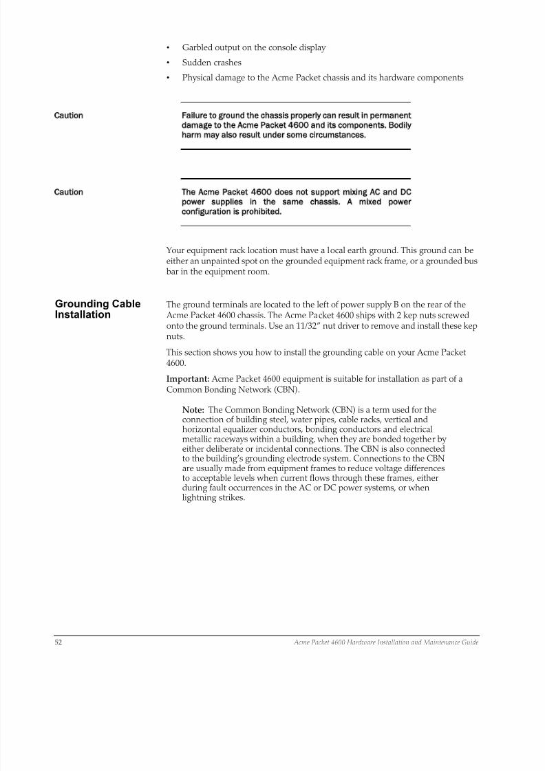
8/15/2019 Installation guide for ACME 4600
http://slidepdf.com/reader/full/installation-guide-for-acme-4600 54/132
52 Acme Packet 4600 Hardware Installation and Maintenance Guide
• Garbled output on the console display
• Sudden crashes
• Physical damage to the Acme Packet chassis and its hardware components
Caution Failure to ground the chassis properly can result in permanent
damage to the Acme Packet 4600 and its components. Bodily
harm may also result under some circumstances.
Caution The Acme Packet 4600 does not support mixing AC and DC
power supplies in the same chassis. A mixed power
configuration is prohibited.
Your equipment rack location must have a local earth ground. This ground can beeither an unpainted spot on the grounded equipment rack frame, or a grounded bus
bar in the equipment room.
Grounding CableInstallation
The ground terminals are located to the left of power supply B on the rear of the Acme Packet 4600 chassis. The Acme Packet 4600 ships with 2 kep nuts screwedonto the ground terminals. Use an 11/32” nut driver to remove and install these kepnuts.
This section shows you how to install the grounding cable on your Acme Packet4600.
Important: Acme Packet 4600 equipment is suitable for installation as part of aCommon Bonding Network (CBN).
Note: The Common Bonding Network (CBN) is a term used for theconnection of building steel, water pipes, cable racks, vertical andhorizontal equalizer conductors, bonding conductors and electricalmetallic raceways within a building, when they are bonded together byeither deliberate or incidental connections. The CBN is also connectedto the building’s grounding electrode system. Connections to the CBNare usually made from equipment frames to reduce voltage differencesto acceptable levels when current flows through these frames, eitherduring fault occurrences in the AC or DC power systems, or whenlightning strikes.
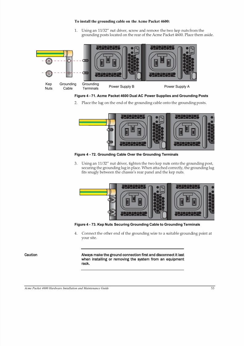
8/15/2019 Installation guide for ACME 4600
http://slidepdf.com/reader/full/installation-guide-for-acme-4600 55/132
Acme Packet 4600 Hardware Installation and Maintenance Guide 53
To install the grounding cable on the Acme Packet 4600:
1. Using an 11/32” nut driver, screw and remove the two kep nuts from thegrounding posts located on the rear of the Acme Packet 4600. Place them aside.
Power Supply B Power Supply AGrounding
Terminals
Grounding
Cable
Kep
Nuts
Figure 4 - 71. Acme Packet 4600 Dual AC Power Supplies and Grounding Posts
2. Place the lug on the end of the grounding cable onto the grounding posts.
Figure 4 - 72. Grounding Cable Over the Grounding Terminals
3. Using an 11/32” nut driver, tighten the two kep nuts onto the grounding post,securing the grounding lug in place. When attached correctly, the grounding lugfits snugly between the chassis’s rear panel and the kep nuts.
Figure 4 - 73. Kep Nuts Securing Grounding Cable to Grounding Terminals
4. Connect the other end of the grounding wire to a suitable grounding point at your site.
Caution Always make the ground connection first and disconnect it last
when installing or removing the system from an equipment
rack.
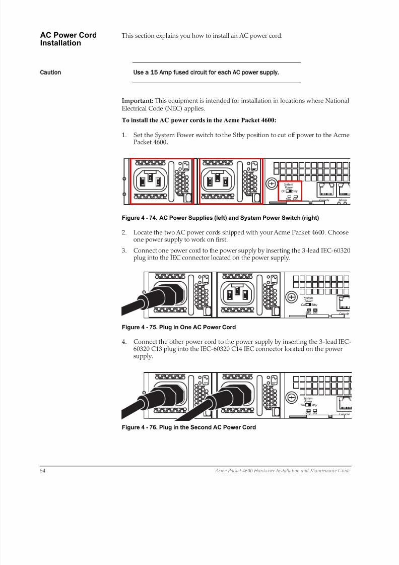
8/15/2019 Installation guide for ACME 4600
http://slidepdf.com/reader/full/installation-guide-for-acme-4600 56/132
54 Acme Packet 4600 Hardware Installation and Maintenance Guide
AC Power CordInstallation
This section explains you how to install an AC power cord.
Caution Use a 15 Amp fused circuit for each AC power supply.
Important: This equipment is intended for installation in locations where NationalElectrical Code (NEC) applies.
To install the AC power cords in the Acme Packet 4600:
1. Set the System Power switch to the Stby position to cut off power to the AcmePacket 4600.
AlarmConsole
SystemPower
On
Stby
Stby
DIS
Figure 4 - 74. AC Power Supplies (left) and System Power Switch (right)
2. Locate the two AC power cords shipped with your Acme Packet 4600. Chooseone power supply to work on first.
3. Connect one power cord to the power supply by inserting the 3-lead IEC-60320plug into the IEC connector located on the power supply.
Console
SystemPower
On
Stby
Stby
DIS
Figure 4 - 75. Plug in One AC Power Cord
4. Connect the other power cord to the power supply by inserting the 3-lead IEC-60320 C13 plug into the IEC-60320 C14 IEC connector located on the powersupply.
Console
SystemPower
On
Stby
Stby
DIS
Figure 4 - 76. Plug in the Second AC Power Cord

8/15/2019 Installation guide for ACME 4600
http://slidepdf.com/reader/full/installation-guide-for-acme-4600 57/132
Acme Packet 4600 Hardware Installation and Maintenance Guide 55
5. Route the AC power cords through your rack and cabling system to the poweroutlets.
6. Plug the supply end of each power cord into its own circuit.
Note: To remove AC power cables from the Acme Packet 4600,reverse the previous steps in this procedure.
7. Set the System Power switch to the On position to provide power to the Acme
Packet 4600. The Acme Packet 4600 will start to boot.
DC Power CordInstallation
This section explains you how to install a DC power cord.
Important: This equipment is intended for installation in NetworkTelecommunication Facilities.
Caution Use a 30 Amp fused circuit for each DC power supply.
Caution Refer to the power supply’s polarity label when connecting it to
a power source. Failure to do so can result in equipment
damage or serious injury.
To install the DC power cords in the Acme Packet 4600:
1. Set the System Power switch to the Stby position to cut off power to the AcmePacket 4600.
AlarmConsole
OUT
IN
OUT
IN
SystemPower
On
Stby
Stby
DIS
Figure 4 - 77. DC Power Supplies (left) and System Power Switch (right)
2. Locate the two DC power cords shipped with your Acme Packet 4600. Chooseone power supply to work on first.
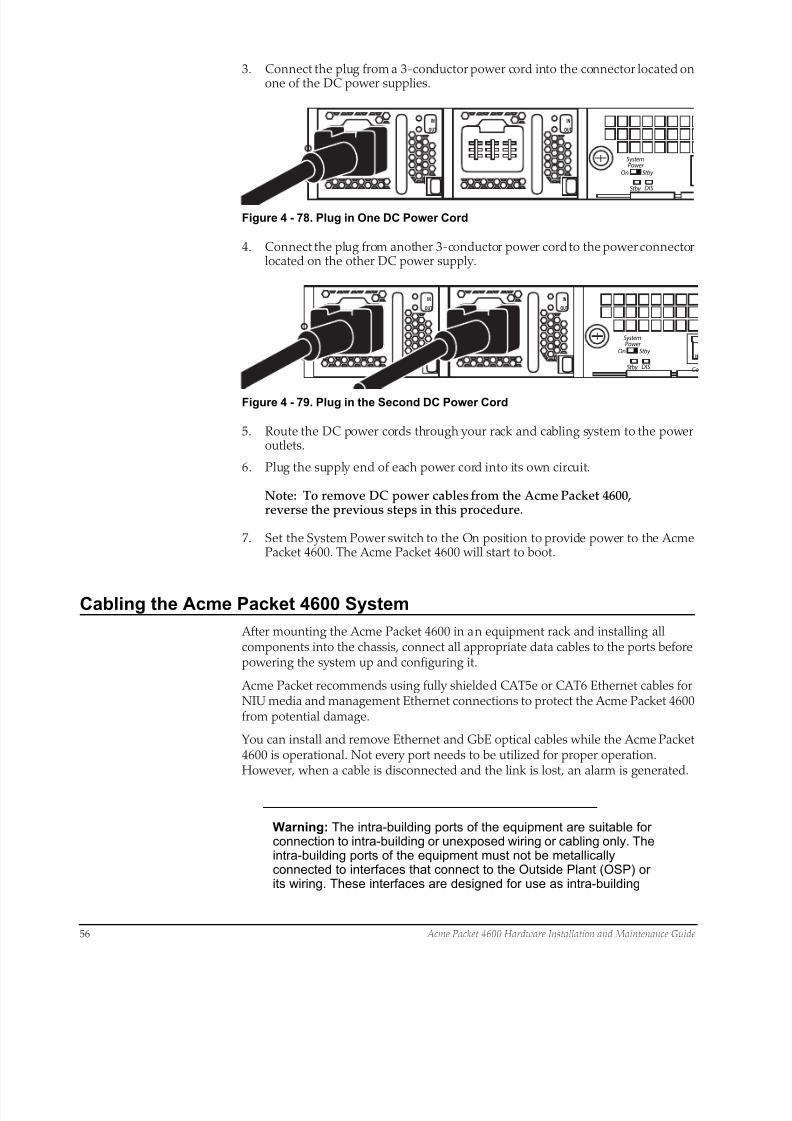
8/15/2019 Installation guide for ACME 4600
http://slidepdf.com/reader/full/installation-guide-for-acme-4600 58/132
56 Acme Packet 4600 Hardware Installation and Maintenance Guide
3. Connect the plug from a 3-conductor power cord into the connector located onone of the DC power supplies.
OUT
IN
OUT
IN
SystemPower
On
Stby
Stby
DIS
Figure 4 - 78. Plug in One DC Power Cord
4. Connect the plug from another 3-conductor power cord to the power connectorlocated on the other DC power supply.
Co
OUT
IN
OUT
IN
SystemPower
On
Stby
Stby
DIS
Figure 4 - 79. Plug in the Second DC Power Cord
5. Route the DC power cords through your rack and cabling system to the poweroutlets.
6. Plug the supply end of each power cord into its own circuit.
Note: To remove DC power cables from the Acme Packet 4600,reverse the previous steps in this procedure.
7. Set the System Power switch to the On position to provide power to the AcmePacket 4600. The Acme Packet 4600 will start to boot.
Cabling the Acme Packet 4600 System
After mounting the Acme Packet 4600 in an equipment rack and installing allcomponents into the chassis, connect all appropriate data cables to the ports beforepowering the system up and configuring it.
Acme Packet recommends using fully shielded CAT5e or CAT6 Ethernet cables forNIU media and management Ethernet connections to protect the Acme Packet 4600from potential damage.
You can install and remove Ethernet and GbE optical cables while the Acme Packet4600 is operational. Not every port needs to be utilized for proper operation.However, when a cable is disconnected and the link is lost, an alarm is generated.
Warning: The intra-building ports of the equipment are suitable forconnection to intra-building or unexposed wiring or cabling only. Theintra-building ports of the equipment must not be metallicallyconnected to interfaces that connect to the Outside Plant (OSP) orits wiring. These interfaces are designed for use as intra-building
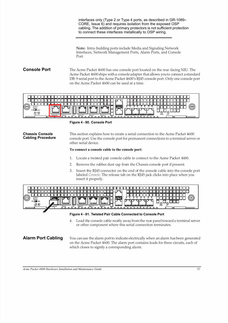
8/15/2019 Installation guide for ACME 4600
http://slidepdf.com/reader/full/installation-guide-for-acme-4600 59/132
Acme Packet 4600 Hardware Installation and Maintenance Guide 57
interfaces only (Type 2 or Type 4 ports, as described in GR-1089–CORE, Issue 6) and requires isolation from the exposed OSPcabling. The addition of primary protectors is not sufficient protectionto connect these interfaces metallically to OSP wiring.
Note: Intra-building ports include Media and Signaling NetworkInterfaces, Network Management Ports, Alarm Ports, and Console
Port.
Console Port The Acme Packet 4600 has one console port located on the rear-facing NIU. The Acme Packet 4600 ships with a console adapter that allows you to connect a standardDB-9 serial port to the Acme Packet 4600’s RJ45 console port. Only one console porton the Acme Packet 4600 can be used at a time.
L
I
N
K
A
C
T
P5
P4
P0 P1 P2 P3PWR H/S
Mgmt 2Mgmt 1Mgmt 0USB AlarmConsole
L IN K A CT L IN K A CT L IN K A CT L IN K A CT SystemPower
On
Stby
Stby
DIS
Figure 4 - 80. Console Port
Chassis ConsoleCabling Procedure
This section explains how to create a serial connection to the Acme Packet 4600console port. Use the console port for permanent connections to a terminal server orother serial device.
To connect a console cable to the console port:
1. Locate a twisted pair console cable to connect to the Acme Packet 4600.
2. Remove the rubber dust cap from the Chassis console port if present.
3. Insert the RJ45 connector on the end of the console cable into the console portlabeled Console. The release tab on the RJ45 jack clicks into place when youinsert it properly.
Figure 4 - 81. Twisted Pair Cable Connected to Console Port
4. Lead the console cable neatly away from the rear panel toward a terminal server
or other component where this serial connection terminates.
Alarm Port Cabling You can use the alarm port to indicate electrically when an alarm has been generatedon the Acme Packet 4600. The alarm port contains leads for three circuits, each of which closes to signify a corresponding alarm.
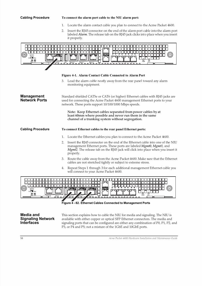
8/15/2019 Installation guide for ACME 4600
http://slidepdf.com/reader/full/installation-guide-for-acme-4600 60/132
58 Acme Packet 4600 Hardware Installation and Maintenance Guide
Cabling Procedure To connect the alarm port cable to the NIU alarm port:
1. Locate the alarm contact cable you plan to connect to the Acme Packet 4600.
2. Insert the RJ45 connector on the end of the alarm port cable into the alarm portlabeled Alarm. The release tab on the RJ45 jack clicks into place when you insertit properly.
L
I
N
K
A
C
T
P5
P4
P0 P1 P2 P3PWR H/S
Mgmt 2Mgmt 1Mgmt 0USB AlarmConsole
L IN K A CT L IN K A CT L IN K A CT L IN K A CT SystemPower
On
Stby
Stby
DIS
Figure 4-1. Alarm Contact Cable Connected to Alarm Port
3. Lead the alarm cable neatly away from the rear panel toward any alarmmonitoring equipment.
Management
Network Ports
Standard shielded CAT5e or CAT6 (or higher) Ethernet cables with RJ45 jacks are
used for connecting the Acme Packet 4600 management Ethernet ports to yournetwork. These ports support 10/100/1000 Mbps speeds.
Note: Keep Ethernet cables separated from power cables by atleast 60mm where possible and never run them in the samechannel of a trunking system without segregation.
Cabling Procedure To connect Ethernet cables to the rear panel Ethernet ports:
1. Locate the Ethernet cables you plan to connect to the Acme Packet 4600.
2. Insert the RJ45 connector on the end of the Ethernet cable into one of the NIUmanagement Ethernet ports. These ports are labeled Mgmt0 , Mgmt1 , and
Mgmt2. The release tab on the RJ45 jack will click into place when you insert itproperly.
3. Route the cable away from the Acme Packet 4600. Make sure that the Ethernetcables are not stretched tightly or subject to extreme stress.
4. Repeat Steps 1 through 3 for each additional management Ethernet cable you will connect to your Acme Packet 4600.
L
I
N
K
A
C
T
P5
P4
P0 P1 P2 P3PWR H/S
Mgmt 2Mgmt 1Mgmt 0USB AlarmConsole
L IN K AC T L IN K AC T L IN K AC T L IN K AC T SystemPower
On
Stby
Stby
DIS
Figure 4 - 82. Ethernet Cables Connected to Management Ports
Media andSignaling NetworkInterfaces
This section explains how to cable the NIU for media and signaling. The NIU isavailable with either copper or optical SFP Ethernet connectors. The media andsignaling ports that can be configured are either any combination of P0, P1, P2, andP3, or P4 and P5; not a mixture of the 1GbE and 10GbE ports.
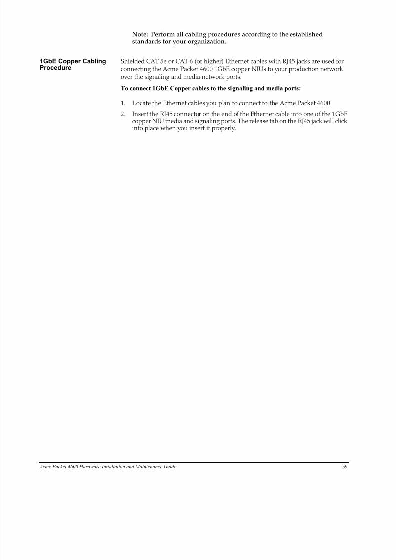
8/15/2019 Installation guide for ACME 4600
http://slidepdf.com/reader/full/installation-guide-for-acme-4600 61/132
Acme Packet 4600 Hardware Installation and Maintenance Guide 59
Note: Perform all cabling procedures according to the establishedstandards for your organization.
1GbE Copper CablingProcedure
Shielded CAT 5e or CAT 6 (or higher) Ethernet cables with RJ45 jacks are used forconnecting the Acme Packet 4600 1GbE copper NIUs to your production networkover the signaling and media network ports.
To connect 1GbE Copper cables to the signaling and media ports:
1. Locate the Ethernet cables you plan to connect to the Acme Packet 4600.
2. Insert the RJ45 connector on the end of the Ethernet cable into one of the 1GbEcopper NIU media and signaling ports. The release tab on the RJ45 jack will clickinto place when you insert it properly.
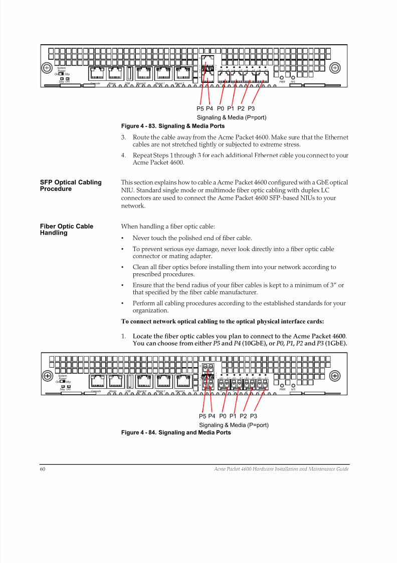
8/15/2019 Installation guide for ACME 4600
http://slidepdf.com/reader/full/installation-guide-for-acme-4600 62/132
P5 P4
Signaling & Media (P=port)
LI
N K
AC
T
P5
P4
P0 P1 P2 P3PWR H/S
Mgmt 2Mgmt 1Mgmt 0USB AlarmConsole
L IN K A CT L I NK A CT L I NK A CT L I NK A CT SystemPower
On
Stby
Stby
DIS
P0 P1 P2 P3
60 Acme Packet 4600 Hardware Installation and Maintenance Guide
Figure 4 - 83. Signaling & Media Ports
3. Route the cable away from the Acme Packet 4600. Make sure that the Ethernetcables are not stretched tightly or subjected to extreme stress.
4. Repeat Steps 1 through 3 for each additional Ethernet cable you connect to your Acme Packet 4600.
SFP Optical CablingProcedure
This section explains how to cable a Acme Packet 4600 configured with a GbE opticalNIU. Standard single mode or multimode fiber optic cabling with duplex LC
connectors are used to connect the Acme Packet 4600 SFP-based NIUs to yournetwork.
Fiber Optic CableHandling
When handling a fiber optic cable:
• Never touch the polished end of fiber cable.
• To prevent serious eye damage, never look directly into a fiber optic cableconnector or mating adapter.
• Clean all fiber optics before installing them into your network according toprescribed procedures.
• Ensure that the bend radius of your fiber cables is kept to a minimum of 3” or
that specified by the fiber cable manufacturer.• Perform all cabling procedures according to the established standards for your
organization.
To connect network optical cabling to the optical physical interface cards:
1. Locate the fiber optic cables you plan to connect to the Acme Packet 4600. You can choose from either P5 and P4 (10GbE), or P0 , P1 , P2 and P3 (1GbE).
L
I
N
K
A
C
T
P5
P4
P0 P1 P2 P3PWR H/S
Mgmt 2Mgmt 1Mgmt 0USB AlarmConsole
L IN K AC T L IN K AC T L IN K AC T L IN K AC T SystemPower
On
Stby
Stby
DIS
P5 P4
Signaling & Media (P=port)
P0 P1 P2 P3
Figure 4 - 84. Signaling and Media Ports
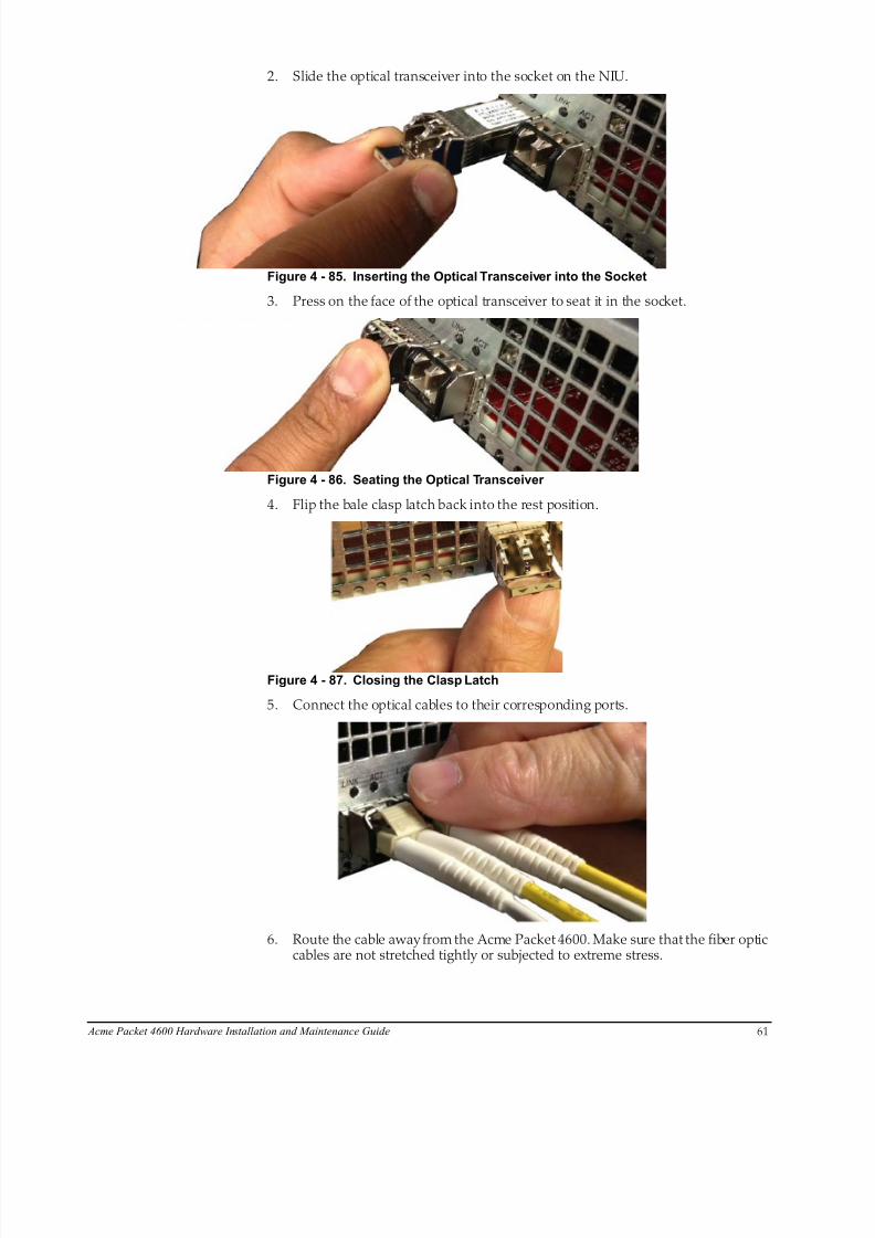
8/15/2019 Installation guide for ACME 4600
http://slidepdf.com/reader/full/installation-guide-for-acme-4600 63/132
Acme Packet 4600 Hardware Installation and Maintenance Guide 61
2. Slide the optical transceiver into the socket on the NIU.
Figure 4 - 85. Inserting the Optical Transceiver into the Socket
3. Press on the face of the optical transceiver to seat it in the socket.
Figure 4 - 86. Seating the Optical Transceiver
4. Flip the bale clasp latch back into the rest position.
Figure 4 - 87. Closing the Clasp Latch
5. Connect the optical cables to their corresponding ports.
6. Route the cable away from the Acme Packet 4600. Make sure that the fiber opticcables are not stretched tightly or subjected to extreme stress.
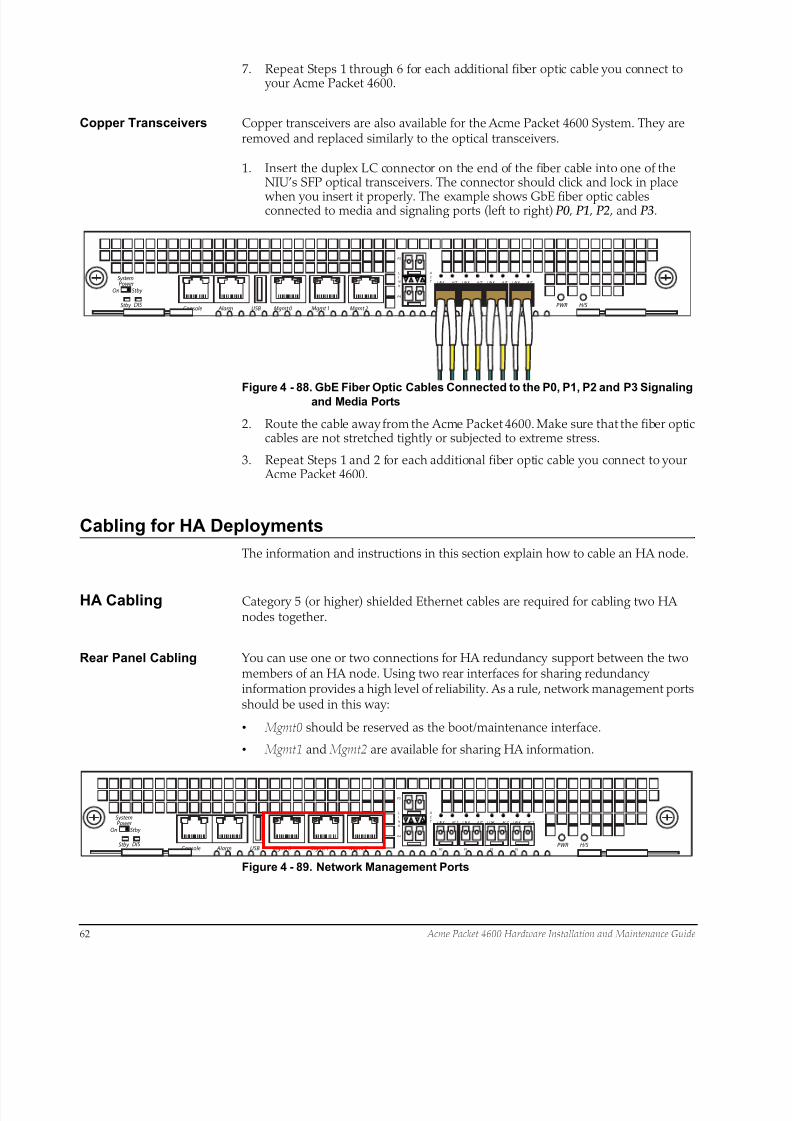
8/15/2019 Installation guide for ACME 4600
http://slidepdf.com/reader/full/installation-guide-for-acme-4600 64/132
62 Acme Packet 4600 Hardware Installation and Maintenance Guide
7. Repeat Steps 1 through 6 for each additional fiber optic cable you connect to your Acme Packet 4600.
Copper Transceivers Copper transceivers are also available for the Acme Packet 4600 System. They areremoved and replaced similarly to the optical transceivers.
1. Insert the duplex LC connector on the end of the fiber cable into one of theNIU’s SFP optical transceivers. The connector should click and lock in place
when you insert it properly. The example shows GbE fiber optic cablesconnected to media and signaling ports (left to right) P0 , P1 , P2 , and P3.
L
I
N
K
A
C
T
P5
P4
P0 P1 P2 P3PWR H/S
Mgmt 2Mgmt 1Mgmt 0USB AlarmConsole
L IN K A CT L IN K A CT L IN K A CT L IN K A CT SystemPower
On
Stby
Stby
DIS
Figure 4 - 88. GbE Fiber Optic Cables Connected to the P0, P1, P2 and P3 Signalingand Media Ports
2. Route the cable away from the Acme Packet 4600. Make sure that the fiber opticcables are not stretched tightly or subjected to extreme stress.
3. Repeat Steps 1 and 2 for each additional fiber optic cable you connect to your Acme Packet 4600.
Cabling for HA Deployments
The information and instructions in this section explain how to cable an HA node.
HA Cabling Category 5 (or higher) shielded Ethernet cables are required for cabling two HAnodes together.
Rear Panel Cabling You can use one or two connections for HA redundancy support between the twomembers of an HA node. Using two rear interfaces for sharing redundancyinformation provides a high level of reliability. As a rule, network management portsshould be used in this way:
• Mgmt0 should be reserved as the boot/maintenance interface.
• Mgmt1 and Mgmt2 are available for sharing HA information.
L
I
N
K
A
C
T
P5
P4
P0 P1 P2 P3PWR H/S
Mgmt 2Mgmt 1Mgmt 0USB AlarmConsole
L IN K AC T L IN K A CT L I NK AC T L IN K AC T SystemPower
On
Stby
Stby
DIS
Figure 4 - 89. Network Management Ports

8/15/2019 Installation guide for ACME 4600
http://slidepdf.com/reader/full/installation-guide-for-acme-4600 65/132
Acme Packet 4600 Hardware Installation and Maintenance Guide 63
Management network ports feature automatic crossover negotiation so that acrossover cable is not necessary for HA cabling.
To cable Acme Packet 4600 in an HA configuration using single rear interface
support:
1. Insert one end of an Ethernet cable into either Mgmt1 or Mgmt2 on the rearpanel of the Acme Packet 4600 A. The release tab on the RJ45 jack clicks intoplace when you insert it properly.
2. Insert the other end of the Ethernet cable into the corresponding managementinterface on the rear panel of the Acme Packet 4600 B. The release tab on theRJ45 jack clicks into place when you insert it properly. If you use Mgmt1 on AcmePacket 4600 A, then you will connect it to Mgmt1 on Acme Packet 4600 B.
L
I N K
AC T
P5
P4
P0 P1 P2 P3P WR H /S
Mgmt2Mgmt1Mgmt0USB AlarmConsole
L I NK A C T LI N K A C T L IN K A C T L IN K A C T
OUT
IN
OUT
IN
SystemPower
On
Stby
Stby
DIS
LI
N K
A
C T
P5
P4
P0 P1 P2 P3P WR H /S
Mgmt2Mgmt1Mgmt0USB AlarmConsole
L I NK A C T LI N K A C T L IN K A C T L IN K A C T
OUT
IN
OUT
IN
SystemPower
On
Stby
Stby
DIS
Acme Packet4600 A
Acme Packet4600 B
Figure 4 - 90. HA Configuration (Either of the Cabling Connections Can Be Used)
3. Refer to the configuration procedures located in the HA Nodes chapter of the Acme Packet Configuration Guide.
To cable Acme Packet 4600 Systems in an HA configuration using dual rear
interface support:
1. Insert one end of an Ethernet cable into Mgmt1 on the rear panel of Acme Packet4600 A. The release tab on the RJ45 jack clicks into place when you insert itproperly.
2. Insert the other end of the cable into the Mgmt1 port on the rear panel of Acme
Packet 4600 B.3. Insert one end of a second Ethernet cable into Mgmt2 on the rear panel of Acme
Packet 4600 A.
4. Insert the other end of the cable into Mgmt2 on the rear panel of Acme Packet4600 B.
LI
N K
A
C T
P5
P4
P0 P1 P2 P3P WR H /S
Mgmt2Mgmt1Mgmt0USB AlarmConsole
L I NK A C T LI N K A C T LI N K A C T L IN K A C T
OUT
IN
OUT
IN
SystemPower
On
Stby
Stby
DIS
LI N
K
AC
T
P5
P4
P0 P1 P2 P3P WR H /S
Mgmt2Mgmt1Mgmt0USB AlarmConsole
L I NK A C T LI N K A C T LI N K A C T L IN K A C T
OUT
IN
OUT
IN
SystemPower
On
Stby
Stby
DIS
Acme Packet
Acme Packet
Figure 4 - 91. HA Configuration (Both of the Cabling Connections Must Be Used)
5. Refer to the configuration procedures located in the HA Nodes chapter of the Acme Packet Configuration Guide.
8/15/2019 Installation guide for ACME 4600
http://slidepdf.com/reader/full/installation-guide-for-acme-4600 66/132
64 Acme Packet 4600 Hardware Installation and Maintenance Guide
Media Cabling for HANodes
NIU media port cabling in an HA node depends on network topology. After aswitchover between the two Acme Packet 4600 s in an HA node, the standby systemsends out an ARP message using a configured virtual MAC address, establishing thatMAC on another physical port on the same Ethernet switch.
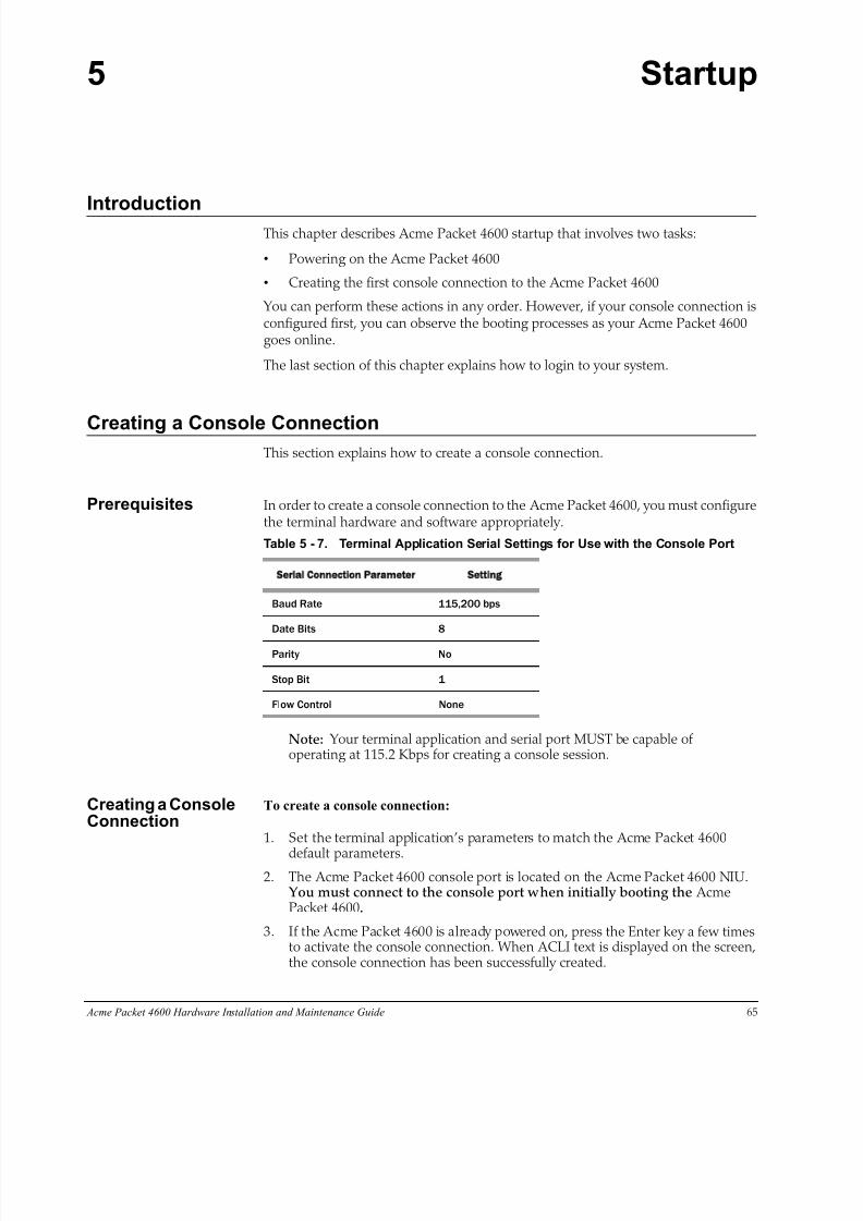
8/15/2019 Installation guide for ACME 4600
http://slidepdf.com/reader/full/installation-guide-for-acme-4600 67/132
Acme Packet 4600 Hardware Installation and Maintenance Guide 65
5 Startup
IntroductionThis chapter describes Acme Packet 4600 startup that involves two tasks:
• Powering on the Acme Packet 4600
• Creating the first console connection to the Acme Packet 4600
You can perform these actions in any order. However, if your console connection isconfigured first, you can observe the booting processes as your Acme Packet 4600goes online.
The last section of this chapter explains how to login to your system.
Creating a Console ConnectionThis section explains how to create a console connection.
Prerequisites In order to create a console connection to the Acme Packet 4600, you must configurethe terminal hardware and software appropriately.
Table 5 - 7. Terminal Application Serial Settings for Use with the Console Port
Serial Connection Parameter Setting
Baud Rate 115,200 bps
Date Bits 8
Parity No
Stop Bit 1
Flow Control None
Note: Your terminal application and serial port MUST be capable ofoperating at 115.2 Kbps for creating a console session.
Creating a ConsoleConnection
To create a console connection:
1. Set the terminal application’s parameters to match the Acme Packet 4600
default parameters.2. The Acme Packet 4600 console port is located on the Acme Packet 4600 NIU.
You must connect to the console port when initially booting the AcmePacket 4600.
3. If the Acme Packet 4600 is already pow ered on, press the Enter key a few timesto activate the console connection. When ACLI text is displayed on the screen,the console connection has been successfully created.
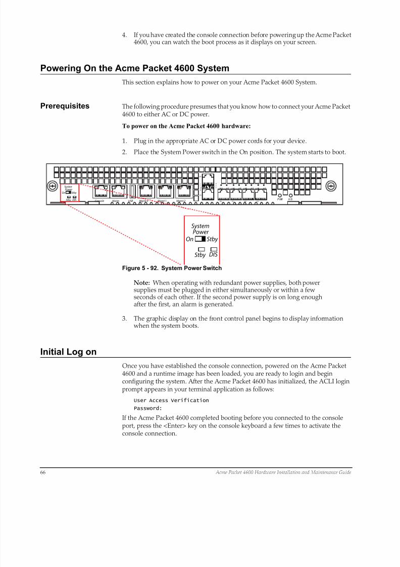
8/15/2019 Installation guide for ACME 4600
http://slidepdf.com/reader/full/installation-guide-for-acme-4600 68/132
66 Acme Packet 4600 Hardware Installation and Maintenance Guide
4. If you have created the console connection before powering up the Acme Packet4600, you can watch the boot process as it displays on your screen.
Powering On the Acme Packet 4600 System
This section explains how to power on your Acme Packet 4600 System.
Prerequisites The following procedure presumes that you know how to connect your Acme Packet4600 to either AC or DC power.
To power on the Acme Packet 4600 hardware:
1. Plug in the appropriate AC or DC power cords for your device.
2. Place the System Power switch in the On position. The system starts to boot.
LI
N K
AC
T
P5
P4
P0 P1 P2 P3P WR H /SMgmt 2Mgmt 1Mgmt 0USB AlarmConsole
L IN K A CT L I NK A CT L I NK A CT L I NK A CT SystemPower
On
Stby
Stby
DIS
SystemPower
On
Stby
Stby
DIS
Figure 5 - 92. System Power Switch
Note: When operating with redundant power supplies, both powersupplies must be plugged in either simultaneously or within a few
seconds of each other. If the second power supply is on long enoughafter the first, an alarm is generated.
3. The graphic display on the front control panel begins to display information when the system boots.
Initial Log on
Once you have established the console connection, powered on the Acme Packet4600 and a runtime image has been loaded, you are ready to login and beginconfiguring the system. After the Acme Packet 4600 has initialized, the ACLI loginprompt appears in your terminal application as follows:
User Access Verification
Password:
If the Acme Packet 4600 completed booting before you connected to the consoleport, press the <Enter> key on the console keyboard a few times to activate theconsole connection.
8/15/2019 Installation guide for ACME 4600
http://slidepdf.com/reader/full/installation-guide-for-acme-4600 69/132
Acme Packet 4600 Hardware Installation and Maintenance Guide 67
System access in the following procedure uses the default User and Superuserpasswords. If you do not have the default passwords, please contact customersupport.
1. At the ACLI Password prompt, enter the default system User password andpress <return>. Your entries are not echoed on the screen.
User Access Verification
Password:ACMEPACKET>
From the User prompt you can view various configuration states and operatingstatistics on the Acme Packet 4600 and perform configuration tasks.
2. Type enable and press <return> to enter Superuser mode. The prompt to enterthe Superuser password appears.
ACMEPACKET> enable
Password:
3. Enter the Superuser password and press <return>. The system prompt will end with a pound sign instead of a closed-angle-bracket to let you know are inSuperuser mode.
Password:
ACMEPACKET#
4. You can now begin configuring your Acme Packet 4600. Refer to the Acme Packet Configuration Guide to learn how to establish an IP address for your Acme Packet 4600.
If you have any questions about booting or powering on your system, please contactcustomer support.
Formatting theSolid State Drive
After the initial log on to the device, you must format the Solid State Drive. Detailson file system designs and the formatting procedure may be found in Chapter 9, FileSystem Maintenance of the Maintenance and Troubleshooting Guide for yoursoftware release.

8/15/2019 Installation guide for ACME 4600
http://slidepdf.com/reader/full/installation-guide-for-acme-4600 70/132
68 Acme Packet 4600 Hardware Installation and Maintenance Guide
8/15/2019 Installation guide for ACME 4600
http://slidepdf.com/reader/full/installation-guide-for-acme-4600 71/132
Acme Packet 4600 Hardware Installation and Maintenance Guide 69
6 Maintenance
IntroductionThis chapter explains Acme Packet 4600 System hardware maintenance procedures.This chapter also provides hardware alarm information.
System Shutdown
Although several user-replaceable components of the Acme Packet 4600 are hot-swappable, some limited Acme Packet 4600 maintenance procedures require that you shut down the system.
Before you shut down or restart the Acme Packet 4600, ensure that there are noactive calls in progress. The command to show active calls is “show sessions.”
ACMEPACKET# show sessions
Procedures to reroute call and network traffic around the Acme Packet 4600 areoutside the scope of this guide.
You can set the Acme Packet 4600 to reject all incoming calls from your system withthe set-system-state command. When set to offline, this command lets calls inprogress continue uninterrupted, but no new calls are admitted.
After all call processing has stopped, you can power off your Acme Packet 4600.Shutting down the system is appropriate when you are replacing a physical interfacecard, power supply, or are removing the Acme Packet 4600 from the equipment rack.
RejectingIncoming Calls
To reject all incoming calls on the Acme Packet 4600 System:
1. In Superuser mode, type show sessions to see all the current calls.
ACMEPACKET# show sessions
2. Type set-system-state offline and press <Enter>.
ACMEPACKET# set system state offline
Setting system state to going-offline, process will complete when allcurrent calls have completed
ACMEPACKET#
Shutting Down the
Acme Packet 4600System
To shut down the Acme Packet 4600 System hardware:
1. In Superuser mode, type halt and then press <Enter>.
2. To confirm the halt request, type Y and then press <Enter>.
3. When the console indicates shutdown is completed, unplug the AC power cordsfrom the power supplies on the rear panel of the Acme Packet 4600.
4. Confirm that the graphic display is dark and all fans are off.
8/15/2019 Installation guide for ACME 4600
http://slidepdf.com/reader/full/installation-guide-for-acme-4600 72/132
70 Acme Packet 4600 Hardware Installation and Maintenance Guide
Rebooting, Resetting, and Power Cycling
Reboot Rebooting the Acme Packet 4600 shuts down the system in an orderly fashion andthen automatically restarts it. The operating system gracefully shuts down asprocesses are terminated and the file system is stopped. While the system and itsprocesses are stopped, all call processing is immediately halted. You may therefore wish to perform tasks that call for a reboot during off-peak maintenance hours.
Rebooting the Acme Packet 4600 is required every time you upgrade with a new version of the Acme Packet 4600 software.
Save your configurations before rebooting the Acme Packet 4600. Refer to the Maintenance and Troubleshooting Guide for a full explanation of this procedure. Thesave-config command is used to save the configuration in the example below.
For a full explanation and all options for the reboot command used in the examplebelow, refer to the ACLI Reference Guide.
To reboot the Acme Packet 4600:
1. Save any configuration changes you have made in the ACLI while in Superusermode by typing save-config <Enter>.
ACMEPACKET# save config
Save-Config received, processing.
waiting 1200 for request to finish
Request to 'SAVE-CONFIG' has Finished,
Save complete
Currently active and saved configurations do not match!
To sync & activate, run 'activate-config' or 'reboot activate'.
ACMEPACKET#
2. Execute the reboot command at the Superuser prompt by typing reboot andthen pressing <Enter>.
ACMEPACKET# reboot
-----------------------------------------
WARNING: you are about to reboot this SD!
3. Type Y and then press <Enter> at the confirmation prompt to proceed with thereboot.
Reboot this SD [y/n]?: y
System Reset Resetting the Acme Packet 4600 via the reset pushbutton on the front of the chassisperforms a cold reboot. This action is the equivalent of disconnecting the power fromthe system and then reconnecting it. There is no orderly termination of tasks, andthe system shuts down abruptly. You should only reset the Acme Packet 4600 when
it becomes unstable and no other means of gaining administrative control ispossible.
During a system reset, certain files are not closed properly, and they may becomecorrupted. If an unclean shutdown is detected, filesystem recovery/repair will be runto ensure the system returns to a stable state. Filesystem verification also runs every30 boots as a precautionary measure.

8/15/2019 Installation guide for ACME 4600
http://slidepdf.com/reader/full/installation-guide-for-acme-4600 73/132
Acme Packet 4600 Hardware Installation and Maintenance Guide 71
Caution Always try to first reboot the Acme Packet 4600 from the ACLI
before performing a cold reset. Only reset the system as a last
resort.
To reset the Acme Packet 4600:
1. Insert a rigid paperclip-sized tool into the small hole on the front of the chassisbeneath the graphic display. The system immediately resets and begins itsinitialization and boot sequence.
Alarm
Alarm
Power
Silence
Acme Packet
AP4600
Figure 6 - 93. Reset Pushbutton
Power Cycling Power Cycling the Acme Packet 4600 is the process of turning the chassis off andthen on again. Unplugging the power cords from the power supplies means toremove power from the system. When power cycling, it is imperative that you waitat least 10 seconds between power down and power up to ensure that allcomponents are completely powered down before restarting the system.
Standby State for HA Nodes
When performing hardware maintenance on the Acme Packet 4600, it is best tominimize any risk of interrupting network traffic or losing data. If the Acme Packet4600s are configured as an HA node, you should only work on the Acme Packet 4600that is in standby state.
There are two ways to determine the HA state of each Acme Packet 4600 in an HApair.
1. If you are in the same physical location as the Acme Packet 4600 you can viewthe graphic display on the front panel. The display will indicate the HA state. Astandby system displays (S) while an active system does not display (S).
2. If you are not in the same physical location as the Acme Packet 4600, you canuse the ACLI show health command. The output of this command indicates the
current HA state of the Acme Packet 4600.
Once you have determined that the Acme Packet 4600 due for maintenance is instandby state, you can continue with the appropriate procedures to replace a part.
If you need to perform maintenance on the active Acme Packet 4600 you need tomanually force the two Acme Packet 4600s to switch HA states. Forcing a switchoverrenders the currently active Acme Packet 4600 in Standby state, and the current

8/15/2019 Installation guide for ACME 4600
http://slidepdf.com/reader/full/installation-guide-for-acme-4600 74/132
72 Acme Packet 4600 Hardware Installation and Maintenance Guide
standby Acme Packet 4600 will assume all traffic processing and forwarding as theactive system.
Caution This procedure is only applicable to Acme Packet 4600 in an
HA deployment.
To force a Acme Packet 4600 into the standby HA state:
1. Confirm that the relevant Acme Packet 4600 systems on active and standby aresynchronized with the show health command. Type show health and press<Enter> on each system as shown in the following.
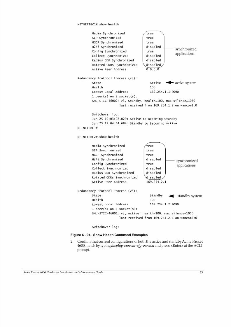
8/15/2019 Installation guide for ACME 4600
http://slidepdf.com/reader/full/installation-guide-for-acme-4600 75/132
NETNETSBC1# show health
Media Synchronized true
SIP Synchronized true
MGCP Synchronized true
H248 Synchronized disabled
Config Synchronized true
Collect Synchronized disabled Radius CDR Synchronized disabled
Rotated CDRs Synchronized disabled
Active Peer Address 0.0.0.0
Redundancy Protocol Process (v3):
State Active
Health 100
Lowest Local Address 169.254.1.1:9090
1 peer(s) on 2 socket(s):
SML-STIC-46002: v3, Standby, health=100, max silence=1050
last received from 169.254.1.2 on wancom1:0
Switchover log: Jun 25 19:03:02.029: Active to Becoming Standby
Jun 25 19:04:54.684: Standby to Becoming Active
NETNETSBC1#
NETNETSBC2# show health
Media Synchronized true
SIP Synchronized true
MGCP Synchronized true
H248 Synchronized disabled
Config Synchronized true
Collect Synchronized disabled
Radius CDR Synchronized disabled
Rotated CDRs Synchronized disabled
Active Peer Address 169.254.2.1
Redundancy Protocol Process (v3):
State Standby
Health 100
Lowest Local Address 169.254.1.2:9090
1 peer(s) on 2 socket(s):
SML-STIC-46001: v3, Active, health=100, max silence=1050
last received from 169.254.2.1 on wancom2:0
Switchover log:
active system
synchronized
standby system
applications
synchronizedapplications
Acme Packet 4600 Hardware Installation and Maintenance Guide 73
Figure 6 - 94. Show Health Command Examples
2. Confirm that current configurations of both the active and standby Acme Packet4600 match by typing display-current-cfg-version and press <Enter> at the ACLIprompt.
8/15/2019 Installation guide for ACME 4600
http://slidepdf.com/reader/full/installation-guide-for-acme-4600 76/132
74 Acme Packet 4600 Hardware Installation and Maintenance Guide
NETNETSBC1# display current cfg version
Current configuration version is 5
NETNETSBC1#
NETNETSBC2# display current cfg version
Current configuration version is 5
NETNETSBC2#
Note: While the two current configuration version numbers on the twosystems do not need to match each other, they MUST match the sharedrunning configuration version.
3. Confirm that running configurations of the active and standby Acme Packet4600 match by typing display-current-cfg-version and press <Enter> at the ACLIprompt.
NETNETSBC1# display running cfg version
Running configuration version is 5
NETNETSBC1#
NETNETSBC2# display running cfg version
Running configuration version is 5
NETNETSBC2#
Note: While the two running configuration version numbers on thetwo systems do not need to match each other, they MUST match theshared current configuration version.
4. Initiate a switchover between active and standby Acme Packet 4600s by typingnotify berpd force on the standby Acme Packet 4600 and then pressing <Enter>at the ACLI prompt.
NETNETSBC1# notify berpd force
5. Wait for the other Acme Packet 4600 to transition to the standby state. Confirmthat it is in the standby state by typing show health and pressing <Enter> at the ACLI prompt.
NETNETSBC2# show health
Refer to the Upgrade section of the Maintenance and Troubleshooting Guide (400-0063-40A) for more information.
Replacing an NIUin an HA Node
When replacing the NIU in an HA node, refer to the following procedure:
1. Prepare all equipment connected to the NIU for the NIU’s removal from thenetwork.
2. Force the system into standby state.
3. Remove the NIU as described in this document.
4. Log in to the ACLI via a console connection.
5. Reboot the system from the ACLI.
When this Acme Packet 4600 returns online, it will synchronize its HA state with theactive HA node using the new NIU. You can confirm the system state by using theshow health command.
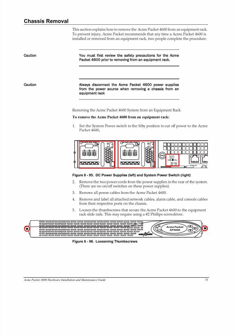
8/15/2019 Installation guide for ACME 4600
http://slidepdf.com/reader/full/installation-guide-for-acme-4600 77/132
Acme Packet 4600 Hardware Installation and Maintenance Guide 75
Chassis Removal
This section explains how to remove the Acme Packet 4600 from an equipment rack.To prevent injury, Acme Packet recommends that any time a Acme Packet 4600 isinstalled or removed from an equipment rack, two people complete the procedure.
Caution You must first review the safety precautions for the Acme
Packet 4600 prior to removing from an equipment rack.
Caution Always disconnect the Acme Packet 4600 power supplies
from the power source when removing a chassis from an
equipment rack
Removing the Acme Packet 4600 System from an Equipment Rack
To remove the Acme Packet 4600 from an equipment rack:
1. Set the System Power switch to the Stby position to cut off power to the AcmePacket 4600.
AlarmConsole
OUT
IN
OUT
IN
SystemPower
On
Stby
Stby
DIS
Figure 6 - 95. DC Power Supplies (left) and System Power Switch (right)2. Remove the two power cords from the power supplies in the rear of the system.
(There are no on/off switches on these power supplies).
3. Remove all power cables from the Acme Packet 4600.
4. Remove and label all attached network cables, alarm cable, and console cablesfrom their respective ports on the chassis.
5. Loosen the thumbscrews that secure the Acme Packet 4600 to the equipmentrack slide rails. This may require using a #2 Phillips screwdriver.
Alarm
Alarm
Power
Silence
Acme Packet
AP4600
Figure 6 - 96. Loosening Thumbscrews
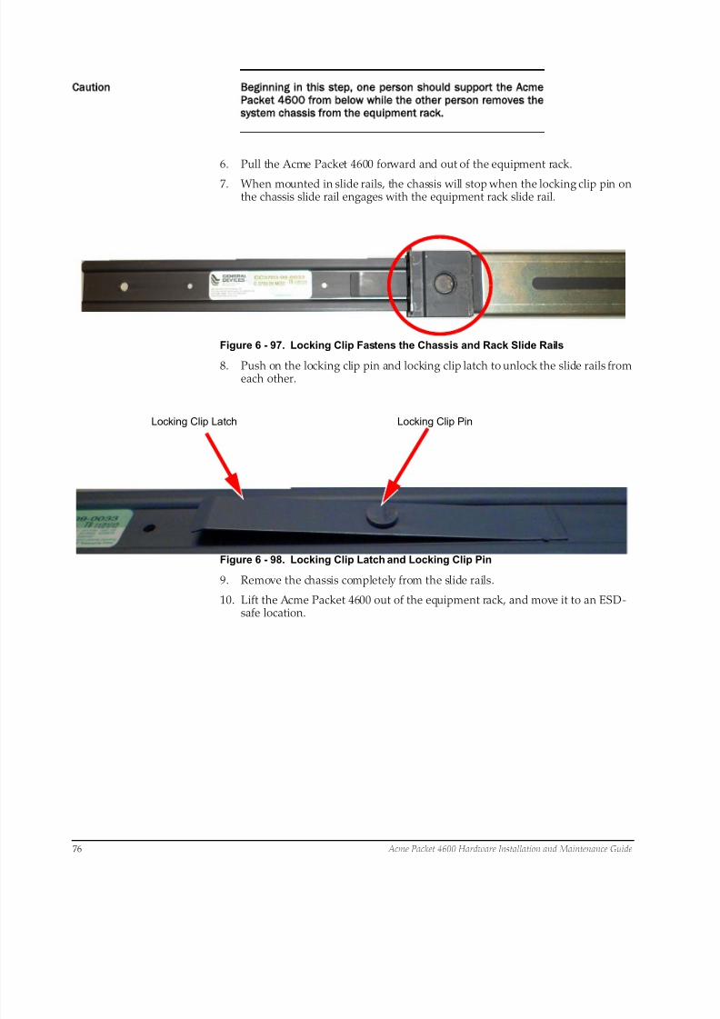
8/15/2019 Installation guide for ACME 4600
http://slidepdf.com/reader/full/installation-guide-for-acme-4600 78/132
76 Acme Packet 4600 Hardware Installation and Maintenance Guide
Caution Beginning in this step one person should support the Acme
Packet 4600 from below while the other person removes the
system chassis from the equipment rack.
6. Pull the Acme Packet 4600 forward and out of the equipment rack.
7. When mounted in slide rails, the chassis will stop when the locking clip pin onthe chassis slide rail engages with the equipment rack slide rail.
Figure 6 - 97. Locking Clip Fastens the Chassis and Rack Slide Rails
8. Push on the locking clip pin and locking clip latch to unlock the slide rails fromeach other.
Locking Clip Latch Locking Clip Pin
Figure 6 - 98. Locking Clip Latch and Locking Clip Pin
9. Remove the chassis completely from the slide rails.
10. Lift the Acme Packet 4600 out of the equipment rack, and move it to an ESD-safe location.
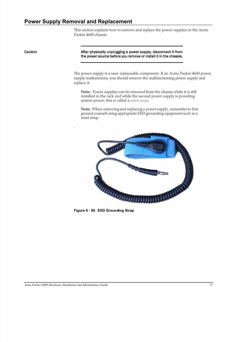
8/15/2019 Installation guide for ACME 4600
http://slidepdf.com/reader/full/installation-guide-for-acme-4600 79/132
Acme Packet 4600 Hardware Installation and Maintenance Guide 77
Power Supply Removal and Replacement
This section explains how to remove and replace the power supplies in the AcmePacket 4600 chassis.
Caution After physically unplugging a power supply disconnect it from
the power source before you remove or install it in the chassis.
The power supply is a user-replaceable component. If an Acme Packet 4600 powersupply malfunctions, you should remove the malfunctioning power supply andreplace it.
Note: Power supplies can be removed from the chassis while it is stillinstalled in the rack and while the second power supply is providingsystem power; this is called a warm swap.
Note: When removing and replacing a power supply, remember to firstground yourself using appropriate ESD grounding equipment such as a
wrist strap..
Figure 6 - 99. ESD Grounding Strap
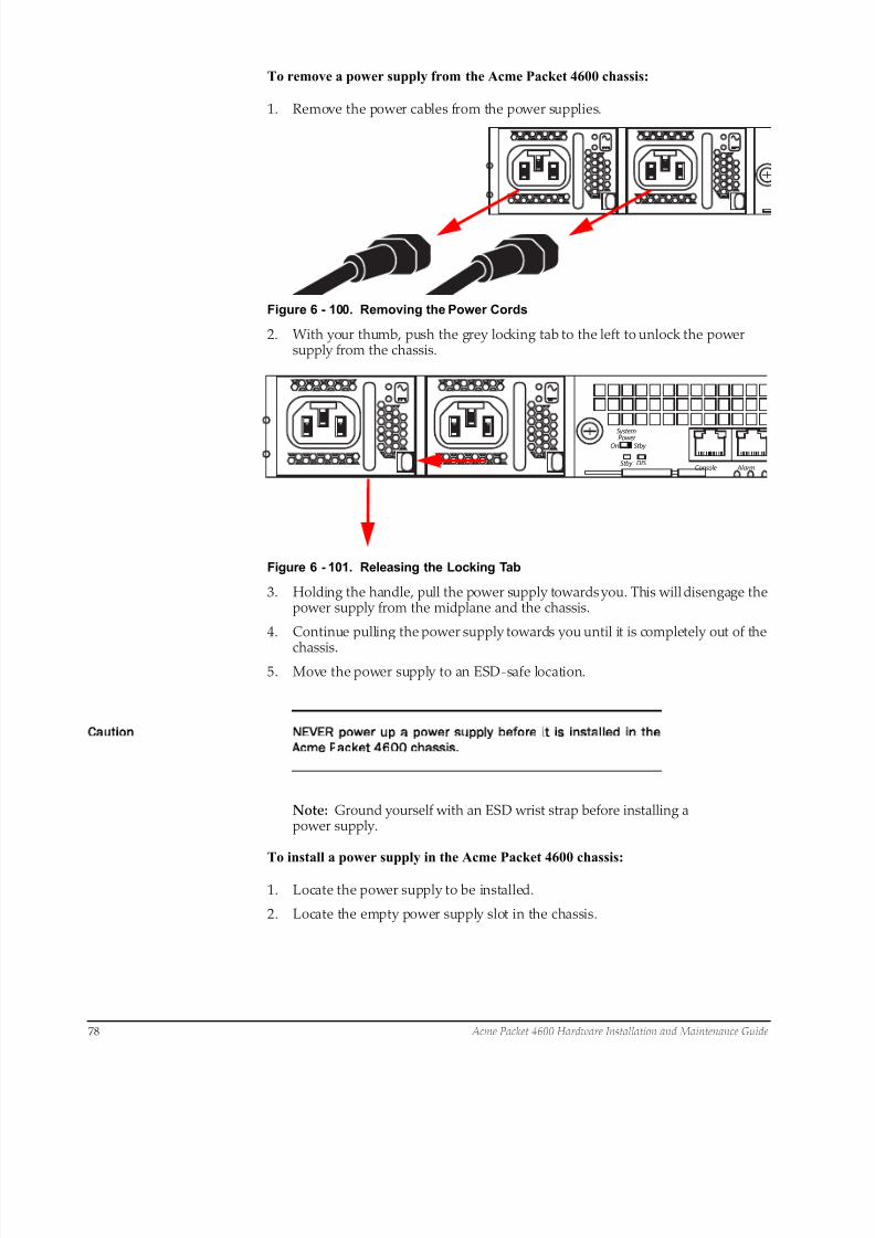
8/15/2019 Installation guide for ACME 4600
http://slidepdf.com/reader/full/installation-guide-for-acme-4600 80/132
78 Acme Packet 4600 Hardware Installation and Maintenance Guide
To remove a power supply from the Acme Packet 4600 chassis:
1. Remove the power cables from the power supplies.
Figure 6 - 100. Removing the Power Cords
2. With your thumb, push the grey locking tab to the left to unlock the powersupply from the chassis.
AlarmConsole
SystemPower On
Stby
Stby
DIS
Figure 6 - 101. Releasing the Locking Tab
3. Holding the handle, pull the power supply towards you. This will disengage thepower supply from the midplane and the chassis.
4. Continue pulling the power supply towards you until it is completely out of the
chassis.5. Move the power supply to an ESD-safe location.
Caution NEVER power up a power supply before it is installed in the
Acme Packet 4600 chassis.
Note: Ground yourself with an ESD wrist strap before installing apower supply.
To install a power supply in the Acme Packet 4600 chassis:
1. Locate the power supply to be installed.
2. Locate the empty power supply slot in the chassis.
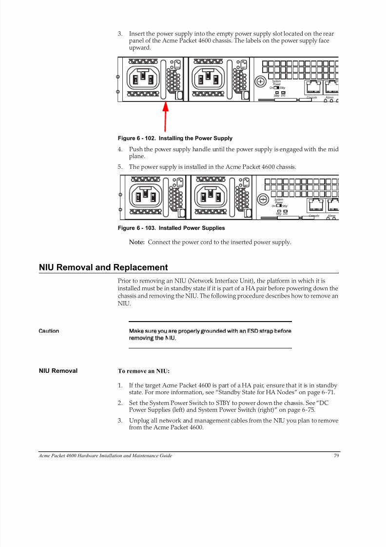
8/15/2019 Installation guide for ACME 4600
http://slidepdf.com/reader/full/installation-guide-for-acme-4600 81/132
Acme Packet 4600 Hardware Installation and Maintenance Guide 79
3. Insert the power supply into the empty power supply slot located on the rearpanel of the Acme Packet 4600 chassis. The labels on the power supply faceupward.
AlarmConsole
SystemPower
On
Stby
Stby
DIS
Figure 6 - 102. Installing the Power Supply
4. Push the power supply handle until the power supply is engaged with the midplane.
5. The power supply is installed in the Acme Packet 4600 chassis.
AlarmConsole
SystemPower
On
Stby
Stby
DIS
Figure 6 - 103. Installed Power Supplies
Note: Connect the power cord to the inserted power supply.
NIU Removal and Replacement
Prior to removing an NIU (Network Interface Unit), the platform in which it is
installed must be in standby state if it is part of a HA pair before powering down thechassis and removing the NIU. The following procedure describes how to remove anNIU.
Caution Make sure you are properly grounded with an ESD strap before
removing the NIU.
NIU Removal To remove an NIU:
1. If the target Acme Packet 4600 is part of a HA pair, ensure that it is in standbystate. For more information, see “Standby State for HA Nodes” on page 6-71.
2. Set the System Power Switch to STBY to power down the chassis. See “DCPower Supplies (left) and System Power Switch (right)” on page 6-75.
3. Unplug all network and management cables from the NIU you plan to removefrom the Acme Packet 4600.
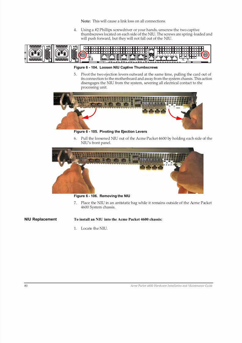
8/15/2019 Installation guide for ACME 4600
http://slidepdf.com/reader/full/installation-guide-for-acme-4600 82/132
80 Acme Packet 4600 Hardware Installation and Maintenance Guide
Note: This will cause a link loss on all connections.
4. Using a #2 Phillips screwdriver or your hands, unscrew the two captivethumbscrews located on each side of the NIU. The screws are spring-loaded and will push forward, but they will not fall out of the NIU.
LI N K
AC T
P5
P4
P0 P1 P2 P3P WR H /S
Mgmt2Mgmt1Mgmt0USB AlarmConsole
L IN K A CT L I NK A CT L I NK A CT L I NK A CT SystemPower
On
Stby
Stby
DIS
Figure 6 - 104. Loosen NIU Captive Thumbscrews
5. Pivot the two ejection levers outward at the same time, pulling the card out ofits connection to the motherboard and away from the system chassis. This actiondisengages the NIU from the system, severing all electrical contact to theprocessing unit.
Figure 6 - 105. Pivoting the Ejection Levers
6. Pull the loosened NIU out of the Acme Packet 4600 by holding each side of theNIU’s front panel.
Figure 6 - 106. Removing the NIU
7. Place the NIU in an antistatic bag while it remains outside of the Acme Packet4600 System chassis.
NIU Replacement To install an NIU into the Acme Packet 4600 chassis:
1. Locate the NIU.
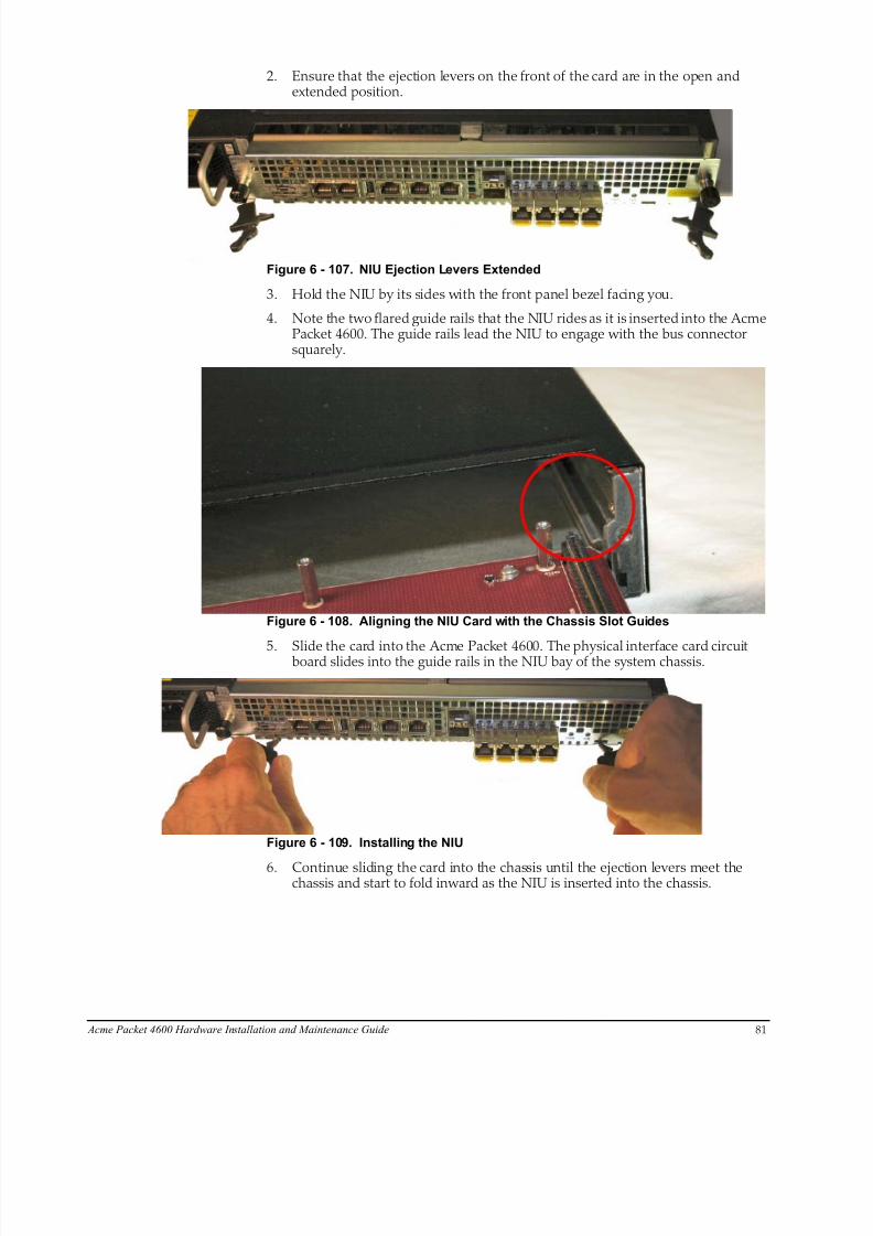
8/15/2019 Installation guide for ACME 4600
http://slidepdf.com/reader/full/installation-guide-for-acme-4600 83/132
Acme Packet 4600 Hardware Installation and Maintenance Guide 81
2. Ensure that the ejection levers on the front of the card are in the open andextended position.
Figure 6 - 107. NIU Ejection Levers Extended
3. Hold the NIU by its sides with the front panel bezel facing you.
4. Note the two flared guide rails that the NIU rides as it is inserted into the AcmePacket 4600. The guide rails lead the NIU to engage with the bus connectorsquarely.
Figure 6 - 108. Aligning the NIU Card with the Chassis Slot Guides
5. Slide the card into the Acme Packet 4600. The physical interface card circuitboard slides into the guide rails in the NIU bay of the system chassis.
Figure 6 - 109. Installing the NIU
6. Continue sliding the card into the chassis until the ejection levers meet thechassis and start to fold inward as the NIU is inserted into the chassis.

8/15/2019 Installation guide for ACME 4600
http://slidepdf.com/reader/full/installation-guide-for-acme-4600 84/132
82 Acme Packet 4600 Hardware Installation and Maintenance Guide
7. Fold both ejection levers inward toward the card to complete the NIUconnection to the motherboard. Pushing the ejection levers inward draws thephysical interface card toward the system chassis and completes the connection.
Figure 6 - 110. Locking the NIU to the Chassis
8. Screw the NIU into the chassis with a #2 Phillips screwdriver. This creates thefinal connection between the interface unit and the chassis.
Figure 6 - 111. Tightening NIU Thumbscrews
9. Replace all network and management cabling.
10. Set the System Power switch to ON to power up the chassis. The system bootsup.
11. If the H/S LED lights in either a steady or flashing state, the NIU is not seatedproperly. If the H/S LED is lit, follow these steps:
11a. Set the System Power switch to STBY to power down the chassis.
11b. Push the ejection levers inward to draw the physical interface card towardthe system chassis and complete the connection. The latches must engageto complete NIU insertion and lock to the chassis.
11c. Set the System Power switch to ON to apply power to the chassis. Thesystem boots up.
11d. When the NIU PWR LED lights and the H/S LED is extinguished, proceed with normal operations. Otherwise, contact customer support for furtherassistance.
8/15/2019 Installation guide for ACME 4600
http://slidepdf.com/reader/full/installation-guide-for-acme-4600 85/132
Acme Packet 4600 Hardware Installation and Maintenance Guide 83
Replacing the SSM3 Module
The SSM3 module that provides TLS security functionality to the Acme Packet 4600is installed on the NIU PCB as shown below. There is a single connector located onthe edge of the NIU into which the SSM3 module plugs; this connector supports oneside of the module while the other side of the SSM3 module rests on four standoffposts.
Pre-InstallationGuidelines
Please read and follow these pre-installation guidelines prior to replacing the SSM3module:
• The SSM3 module can be installed only in the designated location.
• Note the installation location of the SSM3 module on the NIU PCB.
• Ground yourself and follow proper ESD grounding procedures.
• Remove the SSM3 from the shipped packaging.
• Install the SSM3 according to the procedure below.
• This upgrade should be performed during low-traffic periods or during times ofscheduled maintenance.
• Follow industry-standard procedures to ensure ESD protection.• When installing or removing an NIU card, move the card to an ESD-safe
location.
Caution Before handling a Acme Packet 4600 Transcoding NIU card
follow the proper ESD grounding procedures. Failure to do so
could damage the NIU card and its components.
Required Parts The following parts are required to replace the SSM3 module:• ESD wrist strap
• ESD safe location
• SSM3 Module
• NIU Card
Removing theSSM3 Module
The following procedure describes how to remove the SSM3 module located on the Acme Packet NIU card.
Prerequisites:
• Provide an ESD-safe location to place the SSM3 and NIU card.• Wear an ESD wrist strap or take similar equivalent actions to prevent static
damage to the NIU card or other ESD-sensitive components.
• Note the location of the SSM3 module connector on the NIU card.
• #2 Phillips screwdriver
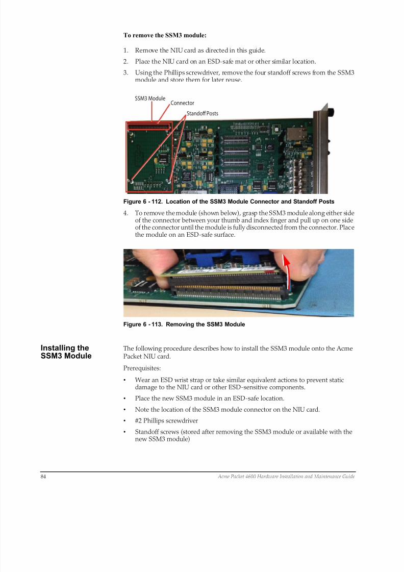
8/15/2019 Installation guide for ACME 4600
http://slidepdf.com/reader/full/installation-guide-for-acme-4600 86/132
84 Acme Packet 4600 Hardware Installation and Maintenance Guide
To remove the SSM3 module:
1. Remove the NIU card as directed in this guide.
2. Place the NIU card on an ESD-safe mat or other similar location.
3. Using the Phillips screwdriver, remove the four standoff screws from the SSM3module and store them for later reuse.
SSM3 Module Connector
Standoff Posts
Figure 6 - 112. Location of the SSM3 Module Connector and Standoff Posts
4. To remove the module (shown below), grasp the SSM3 module along either sideof the connector between your thumb and index finger and pull up on one sideof the connector until the module is fully disconnected from the connector. Placethe module on an ESD-safe surface.
Figure 6 - 113. Removing the SSM3 Module
Installing theSSM3 Module
The following procedure describes how to install the SSM3 module onto the AcmePacket NIU card.
Prerequisites:
• Wear an ESD wrist strap or take similar equivalent actions to prevent staticdamage to the NIU card or other ESD-sensitive components.
• Place the new SSM3 module in an ESD-safe location.• Note the location of the SSM3 module connector on the NIU card.
• #2 Phillips screwdriver
• Standoff screws (stored after removing the SSM3 module or available with thenew SSM3 module)
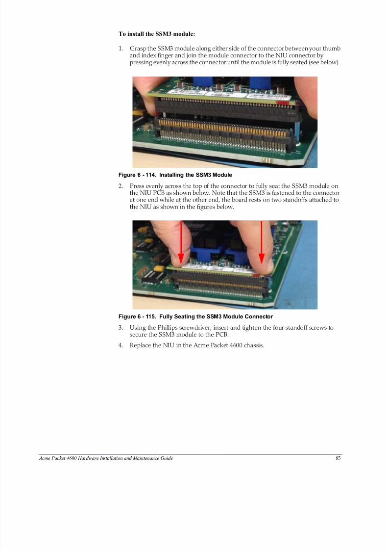
8/15/2019 Installation guide for ACME 4600
http://slidepdf.com/reader/full/installation-guide-for-acme-4600 87/132
Acme Packet 4600 Hardware Installation and Maintenance Guide 85
To install the SSM3 module:
1. Grasp the SSM3 module along either side of the connector between your thumband index finger and join the module connector to the NIU connector bypressing evenly across the connector until the module is fully seated (see below).
Figure 6 - 114. Installing the SSM3 Module
2. Press evenly across the top of the connector to fully seat the SSM3 module on
the NIU PCB as shown below. Note that the SSM3 is fastened to the connectorat one end while at the other end, the board rests on two standoffs attached tothe NIU as shown in the figures below.
Figure 6 - 115. Fully Seating the SSM3 Module Connector
3. Using the Phillips screwdriver, insert and tighten the four standoff screws tosecure the SSM3 module to the PCB.
4. Replace the NIU in the Acme Packet 4600 chassis.

8/15/2019 Installation guide for ACME 4600
http://slidepdf.com/reader/full/installation-guide-for-acme-4600 88/132
SSM3 ModuleConnector
Standoff Posts
86 Acme Packet 4600 Hardware Installation and Maintenance Guide
Figure 6 - 116. Location of the SSM3 Module Connector and Standoff Posts
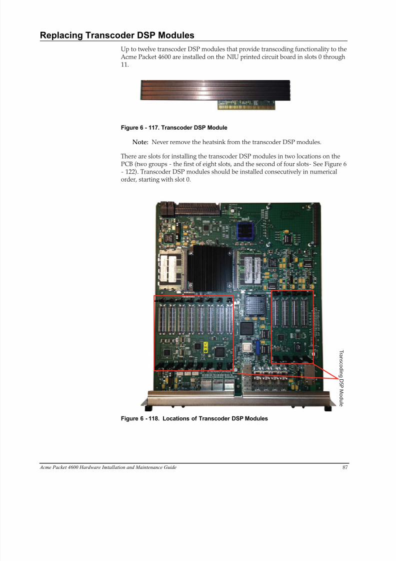
8/15/2019 Installation guide for ACME 4600
http://slidepdf.com/reader/full/installation-guide-for-acme-4600 89/132
Acme Packet 4600 Hardware Installation and Maintenance Guide 87
Replacing Transcoder DSP Modules
Up to twelve transcoder DSP modules that provide transcoding functionality to the Acme Packet 4600 are installed on the NIU printed circuit board in slots 0 through11.
Figure 6 - 117. Transcoder DSP Module
Note: Never remove the heatsink from the transcoder DSP modules.
There are slots for installing the transcoder DSP modules in two locations on thePCB (two groups - the first of eight slots, and the second of four slots- See Figure 6- 122). Transcoder DSP modules should be installed consecutively in numericalorder, starting with slot 0.
T r a n s c o d i n g D S P M o d ul e
Figure 6 - 118. Locations of Transcoder DSP Modules
8/15/2019 Installation guide for ACME 4600
http://slidepdf.com/reader/full/installation-guide-for-acme-4600 90/132
88 Acme Packet 4600 Hardware Installation and Maintenance Guide
Installation andRemovalGuidelines
Please read and follow these guidelines prior to installing or removing the transcoderDSP module:
• The transcoder DSP module can be installed only in the designated location.
• Note the installation locations of the transcoder DSP modules on the NIU PCB.
• Ground yourself and follow proper ESD grounding procedures.
• Remove the transcoder DSP module from the shipped packaging.
• Remove and install the transcoder DSP module according to the proceduresbelow.
• The installation of these modules should be performed during low-trafficperiods or during times of scheduled maintenance.
• Follow industry-standard procedures to ensure ESD protection.
• When installing or removing an NIU card, move the card to an ESD-safelocation.
Caution Before handling a Acme Packet 4600 NIU card follow the
proper ESD grounding procedures. Failure to do so could
damage the NIU card and its components.
Required Parts The following parts are required to replace the transcoder DSP module.
• ESD wrist strap
• ESD-safe location
• Transcoder DSP module
• NIU Card
Removing theTranscoder DSPModule
The following procedure describes how to remove the transcoder DSP module fromthe NIU PCB.
Prerequisites:
• Provide an ESD-safe location to place the transcoder DSP module and NIUcard.
• Wear an ESD wrist strap or take similar equivalent actions to prevent staticdamage to the NIU card or other ESD-sensitive components.
• Note the location of the transcoder DSP module connector on the NIU card.
To remove the transcoder DSP module:
1. Remove the NIU card as directed in this guide. See “NIU Removal andReplacement” on page 6-79.
2. Place the NIU card in an ESD-safe location.
3. To remove the module (as shown in the photos below), use a fingertip to releasethe catch holding either end of the transcoder DSP module.

8/15/2019 Installation guide for ACME 4600
http://slidepdf.com/reader/full/installation-guide-for-acme-4600 91/132
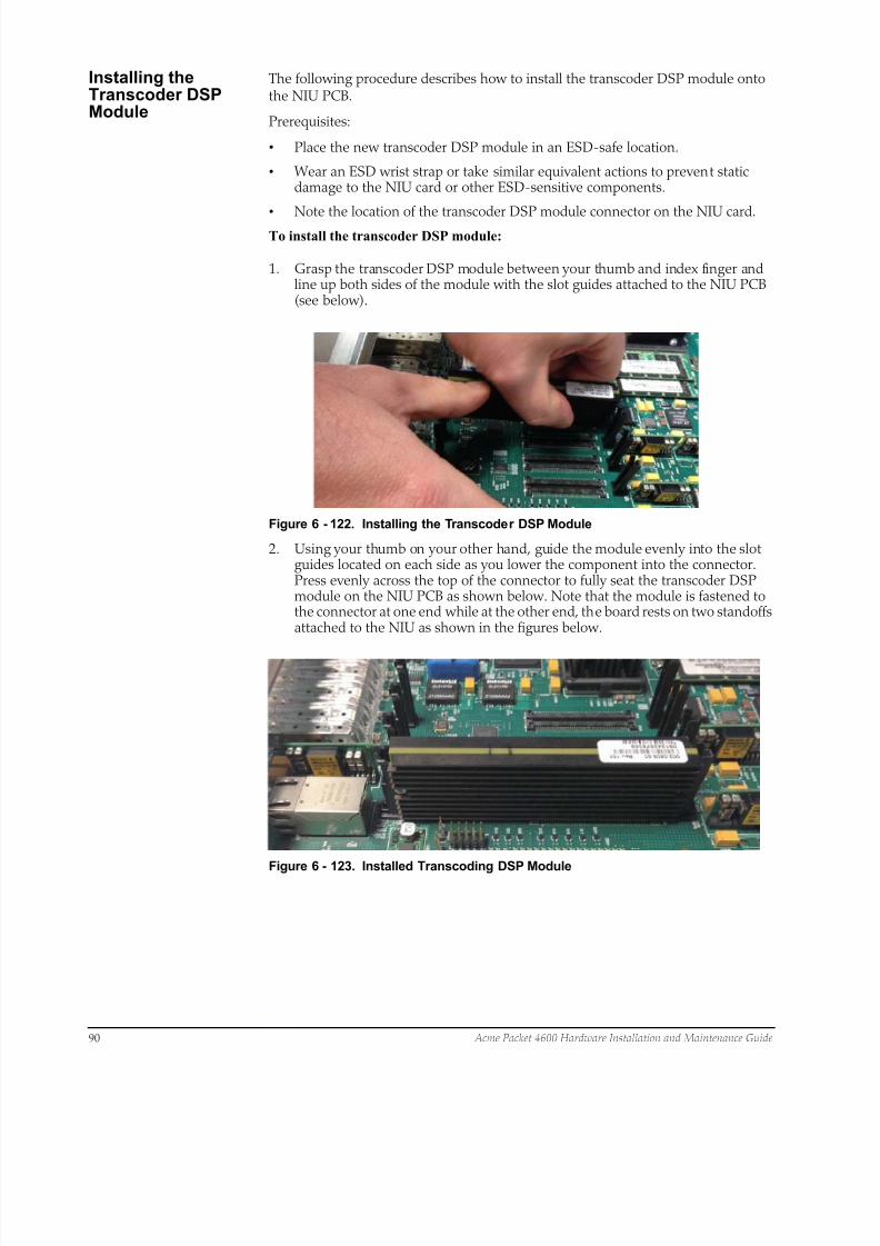
8/15/2019 Installation guide for ACME 4600
http://slidepdf.com/reader/full/installation-guide-for-acme-4600 92/132
90 Acme Packet 4600 Hardware Installation and Maintenance Guide
Installing theTranscoder DSPModule
The following procedure describes how to install the transcoder DSP module ontothe NIU PCB.
Prerequisites:
• Place the new transcoder DSP module in an ESD-safe location.
• Wear an ESD wrist strap or take similar equivalent actions to prevent staticdamage to the NIU card or other ESD-sensitive components.
• Note the location of the transcoder DSP module connector on the NIU card.To install the transcoder DSP module:
1. Grasp the transcoder DSP module between your thumb and index finger andline up both sides of the module with the slot guides attached to the NIU PCB(see below).
Figure 6 - 122. Installing the Transcoder DSP Module
2. Using your thumb on your other hand, guide the module evenly into the slotguides located on each side as you lower the component into the connector.Press evenly across the top of the connector to fully seat the transcoder DSPmodule on the NIU PCB as shown below. Note that the module is fastened tothe connector at one end while at the other end, the board rests on two standoffsattached to the NIU as shown in the figures below.
Figure 6 - 123. Installed Transcoding DSP Module

8/15/2019 Installation guide for ACME 4600
http://slidepdf.com/reader/full/installation-guide-for-acme-4600 93/132
Acme Packet 4600 Hardware Installation and Maintenance Guide 91
Upgrading or Replacing a Solid State Drive
This section explains how to upgrade or replace the Solid State Drive (SSD) in your Acme Packet 4600.
The SSD upgrade or replacement order consists of the drive itself with mountingbrackets and 4 pan head screws (M3 x 5mm) attached.
Installation Toolsand Parts
The following tools and parts are required to install a Solid State Drive in your AcmePacket 4600:
• Solid State Drive
• #1 Phillips-head screwdriver
• #2 Phillips-head screwdriver
• ESD wrist strap
• Cable labels
Pre-removal Perform the following logical and physical preparations before you remove the Solid
State Drive (SSD) from your Acme Packet 4600.
Removing the LogicalSystem from theNetwork
Be mindful of all systems and network entities that may be affected by removing an Acme Packet 4600 from your network. In addition to routing calls around the AcmePacket 4600, you must also prepare network monitoring and health systems toaccommodate the loss of a network element.
Specific procedures for removing the Acme Packet 4600 from your network may befound earlier in this document.
Removing thePhysical System fromthe Equipment Rack
After logically removing the Acme Packet 4600 from your network, the followingprocedures must be completed before you can replace the SSD. These are:
• Disconnection of all media network, management network, alarm and consolecabling from the Acme Packet 4600
• Disconnection of all power and ground system cabling
• Removal of the Acme Packet 4600 from the equipment rack
Removing the DataCabling
Labeling all existing data cables will ease reconnecting the Acme Packet 4600 to thenetwork.
1. Label each cable noting which port on the Acme Packet 4600 it connects to.
2. Attach the appropriate label to each cable.
Remember to label all media network cables , maintenance cabling, and consoleand alarm cables.
3. Disconnect all data cables from the Acme Packet 4600.
Removing Power andGround Cabling
Take care in removing power from the Acme Packet 4600. Refer to the Safety chapterin this document for complete safety guidelines.

8/15/2019 Installation guide for ACME 4600
http://slidepdf.com/reader/full/installation-guide-for-acme-4600 94/132
92 Acme Packet 4600 Hardware Installation and Maintenance Guide
The following is an overview of the power and ground cabling removal process:
1. Shut off power to the Acme Packet 4600 at the circuit breaker or power source.
2. Remove the power cable(s) from the Acme Packet 4600’s power supplies.
3. Unscrew the two kep nuts that secure the grounding cable lug to the AcmePacket 4600.
4. Remove the ground cable. Put the kep nuts in a safe place.
Removing the Chassis The Acme Packet 4600 is heavy, and personal injury can result while removing andinstalling the chassis in an equipment rack. To prevent injury or damage to the AcmePacket system, follow these guidelines:
Caution To prevent personal injury we recommend that two people lift
and install the chassis into the equipment rack.
• Follow your organization’s best practices for lifting and installing heavy
components into an equipment rack.• Ensure that the Acme Packet 4600 remains supported as you remove it from the
equipment rack.
The following is an overview of the chassis removal process. Please refer to theprocedure earlier in this chapter for detailed instructions
1. Use a workbench or other supportive surface, and place it nearby to set the Acme Packet 4600 on after it is removed from the equipment rack.
Support the chassis before and while removing it from the equipment rack.
2. Remove the Acme Packet 4600 from the rack. The number of points to unscrewdepends upon whether the Acme Packet system is installed in a front- or center-mount configuration.
3. Place the chassis on a workbench.
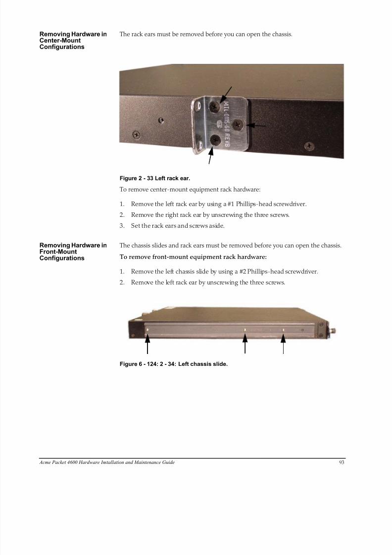
8/15/2019 Installation guide for ACME 4600
http://slidepdf.com/reader/full/installation-guide-for-acme-4600 95/132
Acme Packet 4600 Hardware Installation and Maintenance Guide 93
Removing Hardware inCenter-MountConfigurations
The rack ears must be removed before you can open the chassis.
Figure 2 - 33 Left rack ear.
To remove center-mount equipment rack hardware:
1. Remove the left rack ear by using a #1 Phillips-head screwdriver.
2. Remove the right rack ear by unscrewing the three screws.
3. Set the rack ears and screws aside.
Removing Hardware inFr ont-MountConfigurations
The chassis slides and rack ears must be removed before you can open the chassis.
To remove front-mount equipment rack hardware:
1. Remove the left chassis slide by using a #2 Phillips-head screwdriver.
2. Remove the left rack ear by unscrewing the three screws.
Figure 6 - 124: 2 - 34: Left chassis slide.

8/15/2019 Installation guide for ACME 4600
http://slidepdf.com/reader/full/installation-guide-for-acme-4600 96/132
94 Acme Packet 4600 Hardware Installation and Maintenance Guide
Figure 6 - 125: Figure 2 - 35: Left chassis slide.
3. Remove the the two countersunk screws on the left rear side by using a #1Phillips-head screwdriver.
4. Repeat steps 1 - 3 on the right side of the Acme Packet 4600.
5. Set the rack ears and screws aside
Opening the Chassis The chassis lid is secured to the chassis by 15 screws. Remove the screws and lift thechassis lid off the chassis.
Caution Before opening the Acme Packet 4600 ground yourself using
an ESD wrist strap or other comparable grounding system.
Failure to do so could damage the Solid State Drive and the
Acme Packet 4600.
Note: Use a #2 Phillips-head screwdriver for all chassis cover and sidescrews.
1. Unscrew the four countersunk screws on each side of the Acme Packet 4600 thathold the chassis cover to the chassis.
LEFT SIDE
RIGHT SIDE
Figure 6 - 126: Figure 2-36: Countersunk screws on the sides.
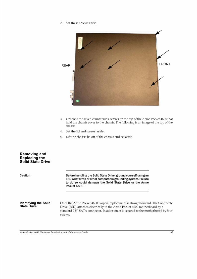
8/15/2019 Installation guide for ACME 4600
http://slidepdf.com/reader/full/installation-guide-for-acme-4600 97/132
Acme Packet 4600 Hardware Installation and Maintenance Guide 95
2. Set these screws aside.
REAR FRONT
3. Unscrew the seven countersunk screws on the top of the Acme Packet 4600 thathold the chassis cover to the chassis. The following is an image of the top of thechassis.
4. Set the lid and screws aside.
5. Lift the chassis lid off of the chassis and set aside.
Removing andReplacing theSolid State Drive
Caution Before handling the Solid State Drive ground yourself using an
ESD wrist strap or other comparable grounding system. Failure
to do so could damage the Solid State Drive or the Acme
Packet 4600.
Identifying the SolidState Drive
Once the Acme Packet 4600 is open, replacement is straightforward. The Solid StateDrive (SSD) attaches electrically to the Acme Packet 4600 motherboard by astandard 2.5” SATA connector. In addition, it is secured to the motherboard by fourscrews.
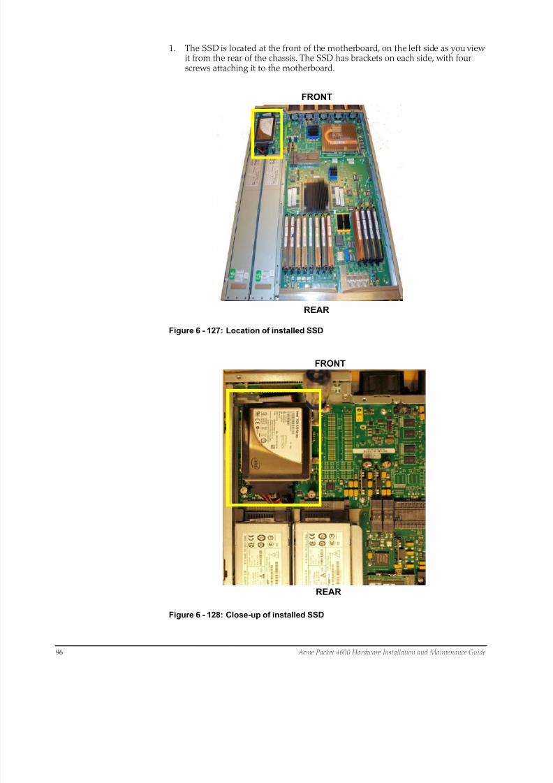
8/15/2019 Installation guide for ACME 4600
http://slidepdf.com/reader/full/installation-guide-for-acme-4600 98/132
96 Acme Packet 4600 Hardware Installation and Maintenance Guide
1. The SSD is located at the front of the motherboard, on the left side as you viewit from the rear of the chassis. The SSD has brackets on each side, with fourscrews attaching it to the motherboard.
REAR
FRONT
Figure 6 - 127: Location of installed SSD
REAR
FRONT
Figure 6 - 128: Close-up of installed SSD
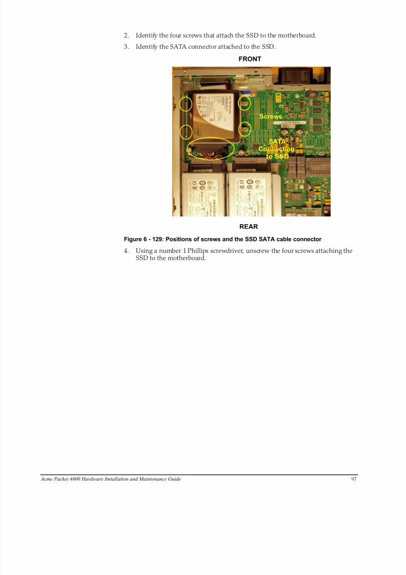
8/15/2019 Installation guide for ACME 4600
http://slidepdf.com/reader/full/installation-guide-for-acme-4600 99/132
Acme Packet 4600 Hardware Installation and Maintenance Guide 97
2. Identify the four screws that attach the SSD to the motherboard.
3. Identify the SATA connector attached to the SSD.
REAR
FRONT
Screws
SATAConnection
to SSD
Figure 6 - 129: Positions of screws and the SSD SATA cable connector
4. Using a number 1 Phillips screwdriver, unscrew the four screws attaching theSSD to the motherboard.
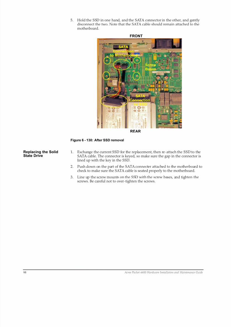
8/15/2019 Installation guide for ACME 4600
http://slidepdf.com/reader/full/installation-guide-for-acme-4600 100/132
98 Acme Packet 4600 Hardware Installation and Maintenance Guide
5. Hold the SSD in one hand, and the SATA connector in the other, and gentlydisconnect the two. Note that the SATA cable should remain attached to themotherboard.
Screw
SATAConnection
to SSD
SATAConnection
to Motherboard
REAR
FRONT
Bases
Figure 6 - 130: After SSD removal
Replacing the SolidState Drive
1. Exchange the current SSD for the replacement, then re-attach the SSD to theSATA cable. The connector is keyed, so make sure the gap in the connector islined up with the key in the SSD.
2. Push down on the part of the SATA connecter attached to the motherboard to
check to make sure the SATA cable is seated properly to the motherboard.3. Line up the screw mounts on the SSD with the screw bases, and tighten the
screws. Be careful not to over-tighten the screws.

8/15/2019 Installation guide for ACME 4600
http://slidepdf.com/reader/full/installation-guide-for-acme-4600 101/132
Acme Packet 4600 Hardware Installation and Maintenance Guide 99
Postinstallation After the Solid State Drive has been installed in the Acme Packet 4600, you can closethe chassis and reinstall it in the equipment rack.
Attaching the Lid Use a #2 Phillips-head screwdriver for all chassis cover and side screws.
1. Set the lid on top of the Acme Packet 4600 chassis. The stickers are positionedat the chassis rear.
2. Screw the eight countersunk screws into the top of the Acme Packet 4600 tosecure the chassis cover to the chassis. The following is an image of the top ofthe chassis without any screws.
REARFRONT
3. Continue securing the chassis lid with four screws on each side.
LEFT SIDE
RIGHT SIDE

8/15/2019 Installation guide for ACME 4600
http://slidepdf.com/reader/full/installation-guide-for-acme-4600 102/132
100 Acme Packet 4600 Hardware Installation and Maintenance Guide
Installing the Chassisin the Rack
Perform the reverse of the operations in the Physical System Removal section of thisdocument.
Please refer to earlier sections of this document for full rack installation procedures.
Validating the SSD Oracle recommends that you validate the Solid State Drive installation by running Acme Packet Session Director diagnostics. All versions from nnCX_diags110.gz andlater include the appropriate tests for validating the SSD. Please refer to the
diagnostics documentation for more information.
In the following procedure, after booting into diagnostics, this preliminary checkensures that the system recognizes the Solid State Drive.
Password: ******
-> dc
/boot/ - Volume is OK
243 MB
/code/ - Volume is OK 245 MB
/sata/ - Drive Present
476940 MB
Starting Diagnostic Executive...
Comm Express MCH 945 Present.
AHCI Support is Enabled.
Acme Packet Net-Net 4600
Diagnostic Executive Version 1.10
Creation date: Nov 25 2014 11:08:02
Board Level Diagnostics
Date & Time: TUE NOV 25 14:56:01 2014
[diag_proc] ->
Formatting the SSD After installing the Solid State Drive, you must format it. Details on file systemdesigns and the formatting procedure may be found in Chapter 9, File SystemMaintenance of the Maintenance and Troubleshooting Guide for your softwarerelease.
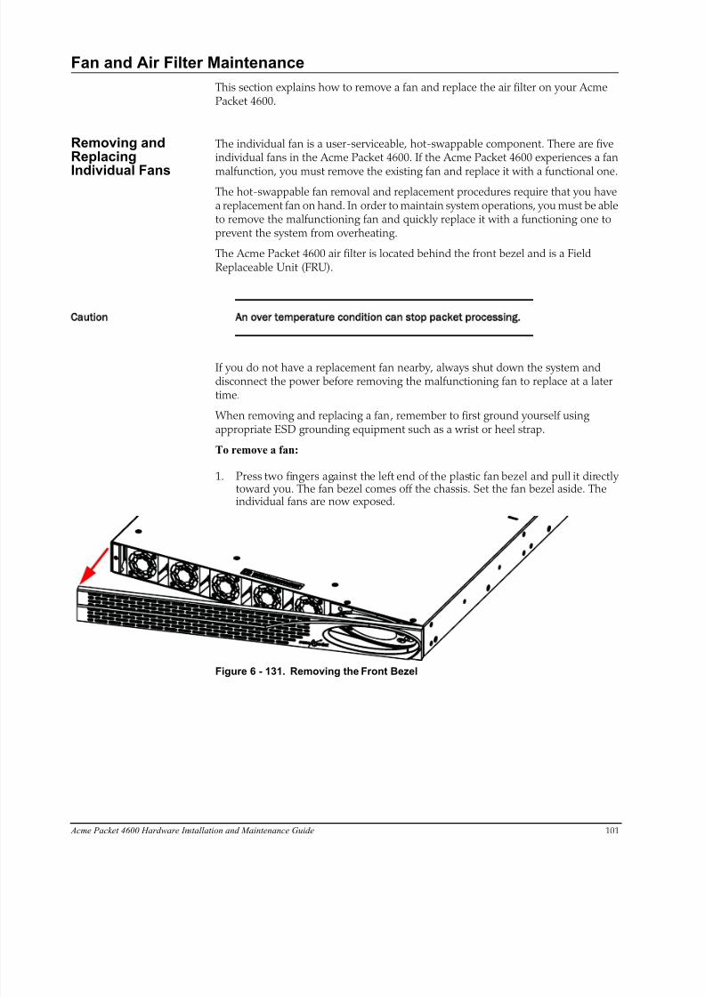
8/15/2019 Installation guide for ACME 4600
http://slidepdf.com/reader/full/installation-guide-for-acme-4600 103/132
Acme Packet 4600 Hardware Installation and Maintenance Guide 101
Fan and Air Filter Maintenance
This section explains how to remove a fan and replace the air filter on your AcmePacket 4600.
Removing andReplacing
Individual Fans
The individual fan is a user-serviceable, hot-swappable component. There are fiveindividual fans in the Acme Packet 4600. If the Acme Packet 4600 experiences a fan
malfunction, you must remove the existing fan and replace it with a functional one.The hot-swappable fan removal and replacement procedures require that you havea replacement fan on hand. In order to maintain system operations, you must be ableto remove the malfunctioning fan and quickly replace it with a functioning one toprevent the system from overheating.
The Acme Packet 4600 air filter is located behind the front bezel and is a FieldReplaceable Unit (FRU).
Caution An over temperature condition can stop packet processing.
If you do not have a replacement fan nearby, always shut down the system anddisconnect the power before removing the malfunctioning fan to replace at a latertime.
When removing and replacing a fan, remember to first ground yourself usingappropriate ESD grounding equipment such as a wrist or heel strap.
To remove a fan:
1. Press two fingers against the left end of the plastic fan bezel and pull it directlytoward you. The fan bezel comes off the chassis. Set the fan bezel aside. Theindividual fans are now exposed.
Figure 6 - 131. Removing the Front Bezel

8/15/2019 Installation guide for ACME 4600
http://slidepdf.com/reader/full/installation-guide-for-acme-4600 104/132
102 Acme Packet 4600 Hardware Installation and Maintenance Guide
2. Using a small bladed screwdriver, unscrew the two captive screws at each upperleft and lower right corners of the individual fan you are replacing.
Figure 6 - 132. Loosening Fan-Fastening Screws
3. Pull the individual fan you just unscrewed directly toward you, out of thechassis. Move the fan to an ESD-safe location.
Figure 6 - 133. Removing the Fan
Install IndividualFans
To obtain a replacement fan, contact customer support.
Replacing the fan is the reverse process as removing it.
To install a fan:
Note: The power connector should be on the lower side of the module when inserted
into the Acme Packet 4600 chassis.
1. Carefully align the pins on the back of the fan with the holes in the chassismidplane and install the fan into the slot.
Figure 6 - 134. Fan Slot Pin Holes
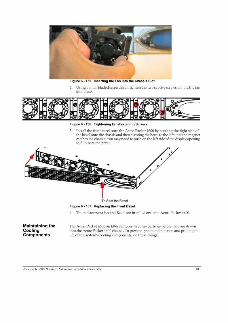
8/15/2019 Installation guide for ACME 4600
http://slidepdf.com/reader/full/installation-guide-for-acme-4600 105/132
Acme Packet 4600 Hardware Installation and Maintenance Guide 103
Figure 6 - 135. Inserting the Fan into the Chassis Slot
2. Using a small bladed screwdriver, tighten the two captive screws to hold the faninto place.
Figure 6 - 136. Tightening Fan-Fastening Screws
3. Install the front bezel onto the Acme Packet 4600 by hooking the right side ofthe bezel onto the chassis and then pivoting the bezel to the left until the magnetcatches the chassis. You may need to push on the left side of the display openingto fully seat the bezel.
To Seat the Bezel
Figure 6 - 137. Replacing the Front Bezel
4. The replacement fan and Bezel are installed onto the Acme Packet 4600.
Maintaining theCoolingComponents
The Acme Packet 4600 air filter removes airborne particles before they are drawninto the Acme Packet 4600 chassis. To prevent system malfunction and prolong thelife of the system’s cooling components, do these things:
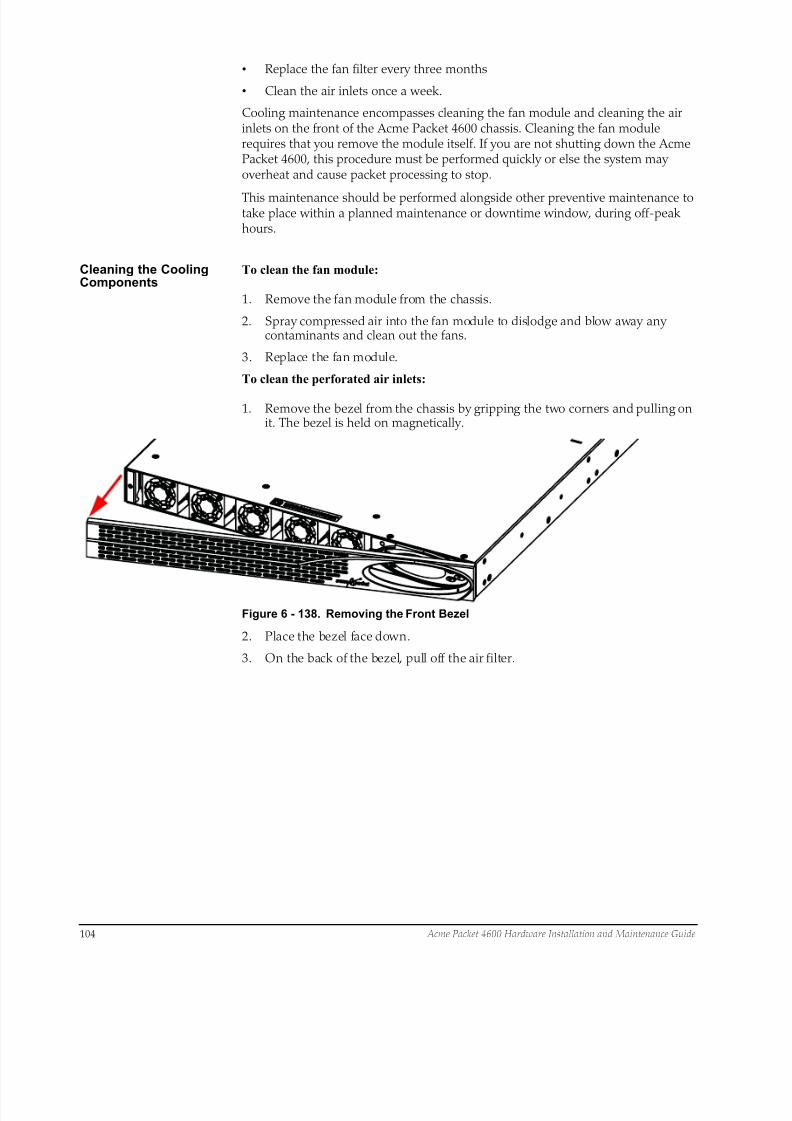
8/15/2019 Installation guide for ACME 4600
http://slidepdf.com/reader/full/installation-guide-for-acme-4600 106/132
104 Acme Packet 4600 Hardware Installation and Maintenance Guide
• Replace the fan filter every three months
• Clean the air inlets once a week.
Cooling maintenance encompasses cleaning the fan module and cleaning the airinlets on the front of the Acme Packet 4600 chassis. Cleaning the fan modulerequires that you remove the module itself. If you are not shutting down the AcmePacket 4600, this procedure must be performed quickly or else the system mayoverheat and cause packet processing to stop.
This maintenance should be performed alongside other preventive maintenance totake place within a planned maintenance or downtime window, during off-peakhours.
Cleaning the CoolingComponents
To clean the fan module:
1. Remove the fan module from the chassis.
2. Spray compressed air into the fan module to dislodge and blow away anycontaminants and clean out the fans.
3. Replace the fan module.
To clean the perforated air inlets:
1. Remove the bezel from the chassis by gripping the two corners and pulling onit. The bezel is held on magnetically.
Figure 6 - 138. Removing the Front Bezel
2. Place the bezel face down.
3. On the back of the bezel, pull off the air filter.
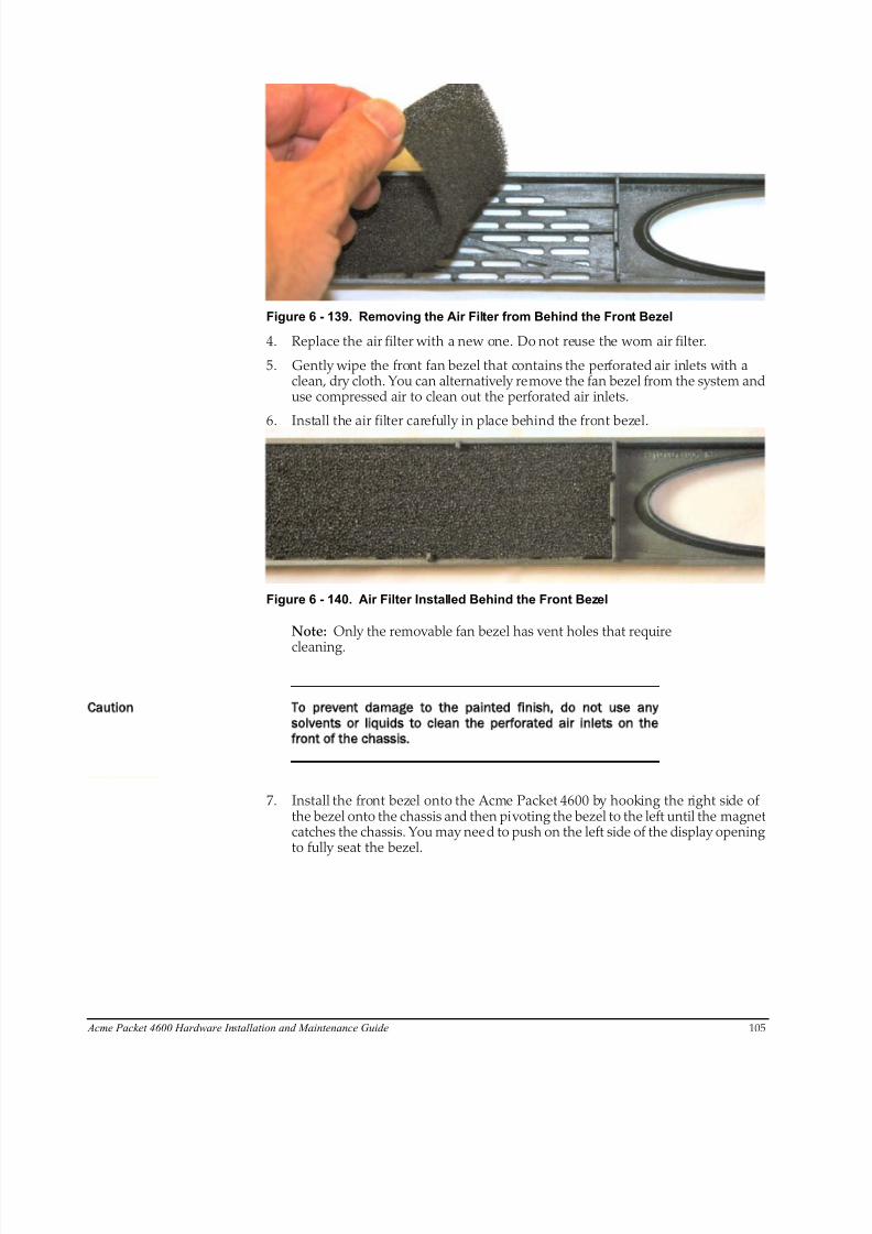
8/15/2019 Installation guide for ACME 4600
http://slidepdf.com/reader/full/installation-guide-for-acme-4600 107/132
Acme Packet 4600 Hardware Installation and Maintenance Guide 105
Figure 6 - 139. Removing the Air Filter from Behind the Front Bezel
4. Replace the air filter with a new one. Do not reuse the worn air filter.
5. Gently wipe the front fan bezel that contains the perforated air inlets with aclean, dry cloth. You can alternatively remove the fan bezel from the system anduse compressed air to clean out the perforated air inlets.
6. Install the air filter carefully in place behind the front bezel.
Figure 6 - 140. Air Filter Installed Behind the Front Bezel
Note: Only the removable fan bezel has vent holes that require
cleaning.
Caution To prevent damage to the painted finish do not use any
solvents or liquids to clean the perforated air inlets on the
front of the chassis.
7. Install the front bezel onto the Acme Packet 4600 by hooking the right side ofthe bezel onto the chassis and then pivoting the bezel to the left until the magnetcatches the chassis. You may need to push on the left side of the display openingto fully seat the bezel.

8/15/2019 Installation guide for ACME 4600
http://slidepdf.com/reader/full/installation-guide-for-acme-4600 108/132
To Seat the Bezel
106 Acme Packet 4600 Hardware Installation and Maintenance Guide
Figure 6 - 141. Replacing the Front Bezel
Optical Transceiver Removal and Replacement
Your troubleshooting and diagnostics might reveal that the optical transceivercomponent of an optical physical interface card needs to be replaced. The opticaltransceiver serves two functions:
• Converts electrical signals into optical signals used to communicate with otheroptical networking equipment.
• Serves as the receptacle for the LC duplex fiber optic connectors.
Optical transceivers are hot swappable and may be replaced while the Acme Packet4600 is powered on. Leave the NIU installed in the Acme Packet 4600 as you extractthe optical transceiver.
To obtain a replacement optical transceiver, contact customer support.
Caution To prevent damage to the optical lens Acme Packet
recommends that the protective dust cover stay on the optical
transceiver port when the physical interface card is not cabled.
Removing an OpticalTransceiver
To remove the transceiver from an NIU transceiver port:
1. Unplug all fiber optic cables from the optical transceiver to be replaced.
Figure 6 - 142. NIU Transceiver Ports

8/15/2019 Installation guide for ACME 4600
http://slidepdf.com/reader/full/installation-guide-for-acme-4600 109/132
Acme Packet 4600 Hardware Installation and Maintenance Guide 107
2. Pull the bale clasp latch out and down. It will pivot downwards on its hinge.
Figure 6 - 143. Lowering the Bale Clasp Latch
3. Holding the extended bale clasp latch, pull the optical transceiver fully out of itssocket of the physical interface card.
Figure 6 - 144. Removing the Optical Transceiver
Install an OpticalTransceiver
To install an optical transceiver:
1. Slide the replacement optical transceiver into the socket on the NIU.
Figure 6 - 145. Inserting the Optical Transceiver into the Socket

8/15/2019 Installation guide for ACME 4600
http://slidepdf.com/reader/full/installation-guide-for-acme-4600 110/132
108 Acme Packet 4600 Hardware Installation and Maintenance Guide
2. Press on the face of the optical transceiver to seat it in the socket.
Figure 6 - 146. Seating the Optical Transceiver
3. Flip the bale clasp latch back into the rest position.
Figure 6 - 147. Closing the Clasp Latch
4. Reconnect the optical cables to their corresponding ports.
5. Reconnecting Optical Cables
Copper Transceivers Copper transceivers are also available for the Acme Packet 4600 System. They areremoved and replaced similarly to the optical transceivers.
Alarms
The Acme Packet 4600 generates internal alarms that correspond to internalhardware fault conditions. Hardware faults are divided into two types:
• Hardware and environmental
• Media link
Each alarm is assigned a severity level, depending on the details of the fault.
8/15/2019 Installation guide for ACME 4600
http://slidepdf.com/reader/full/installation-guide-for-acme-4600 111/132
Table 6 - 8. Descriptions of Alarm Severity Levels
Alarm Severity Description
Minor Functional ity is impai red to a small degree (e.g., a single fan has failed)
Major Pending failures or unexpected events are imminent (e.g., an LOS)
Critical Catastrophic condi tion has occurred (e.g., the system is overheating)
Acme Packet 4600 Hardware Installation and Maintenance Guide 109
The Acme Packet 4600 polls its hardware components to ensure they are functioningproperly. If it encounters a fault condition, it will report alarms in these categories:
• Hardware temperature
• Fan speed
• Environmental sensor
• Power supply
• Voltage
• Physical interface cards
Hardware andEnvironmentalAlarms
This section provides details about hardware and environmental alarms.
HardwareTemperature Alarm
The following table lists the hardware temperature alarm.
Table 6 - 9. Hardware Temperature Alarm Information
Alarm Name
Alarm
ID
Alarm Severity Causes Example Log Message
Graphic Display Window
Message
TEMPERATURE
HIGH
65538 CRITICAL: >105°C
MINOR: >95°C
Fans are obstructed
or stopped. The room
is abnormally hot.
Temperature: XX.XXC
(where XX.XX is the
temperature in
degrees)
Temperature X C (where X
is the temperature in
degrees)
If this alarm occurs, the Acme Packet 4600 turns the fan speed up to the fastest possible speed.
Fan Speed Alarms The following table lists the fan speed alarm.
MAJOR: >100°C
8/15/2019 Installation guide for ACME 4600
http://slidepdf.com/reader/full/installation-guide-for-acme-4600 112/132
Table 6 - 10. Fan Speed Alarm Information
Alarm Name
Alarm
ID
Alarm Severity Causes
Example Log
Message
Graphic Display
Window Message
FAN STOPPED 65537 CRITICAL: any fan speed is <50%. Or
speed of two or more fans is >50% and
<75%.
MINOR: speed of one fan> 75% and
<90%, the other two fans are at normal
speed
Fan failure. Fan speed: XXXX
XXXX XXXX
where xxxx xxxx
xxxx is the revolu-
tions per minute
(RPM) of each fan
on the fan module
Fan stopped
If this alarm occurs, the Acme Packet 4600 turns the fan speed up to the fastest possible speed.
110 Acme Packet 4600 Hardware Installation and Maintenance Guide
Environmental SensorAlarm
The following table lists the environmental sensor alarm.
Table 6 - 11. Environmental Sensor Alarm Information
Alarm Name
Alarm
ID
Alarm Severity Cause s) Example Log Message
Graphic Display
Window Message
ENVIRONMENTAL
SENSOR FAILURE
65539 CRITICAL The environmental sen-
sor component cannot
detect fan speed and
temperature.
Hardware monitor fail-
ure! Unable to monitor
fan speed and tempera-
ture!
HW Monitor Fail
Power Supply Alarms The following table lists the power supply alarms.
Table 6 - 12. Power Supply Alarm Information
Alarm Alarm ID Alarm Severity Causes Log Message
Graphic Display Window
Message
PLD POWER A
FAILURE
65540 MINOR Power supply A has
failed.
Back Power Supply A has
failed!
X HW ALARMS: (where X is the
number of hardware alarms
PLD POWER A
UP
65541 MINOR Power supply A is
now present and
functioning.
Back Power Supply A is
present!
X HW ALARMS: (where X is the
number of hardware alarms
PLD POWER B
FAILURE
65542 MINOR Power supply B has
failed.
Back Power Supply B has
failed!
X HW ALARMS: (where X is the
number of hardware alarms
PLD POWER B
UP
65543 MINOR Power supply B is
now present and
functioning.
Back Power Supply B is
present!
X HW ALARMS: (where X is the
number of hardware alarms
Voltage Alarms The following table lists the voltage alarms.
MAJOR: speed of two or more fans is
> 75% and < 90%. Or speed of one fan is
>50% and <75% and the other two fans
are at normal speed.
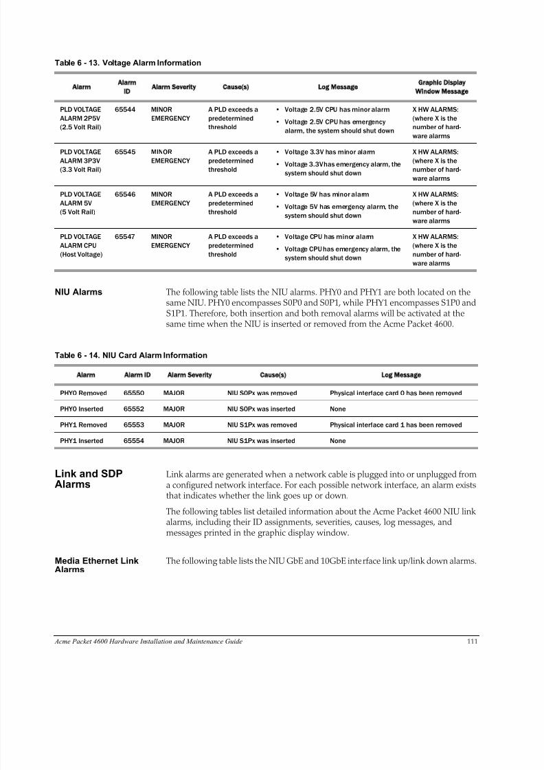
8/15/2019 Installation guide for ACME 4600
http://slidepdf.com/reader/full/installation-guide-for-acme-4600 113/132
Table 6 - 13. Voltage Alarm Information
Alarm
Alarm
ID
Alarm Severity Cause s) Log Message
Graphic Display
Window Message
PLD VOLTAGE
ALARM 2P5V
(2.5 Volt Rail)
65544 MINOR
EMERGENCY
A PLD exceeds a
predetermined
threshold
• Voltage 2.5V CPU has minor alarm
• Voltage 2.5V CPU has emergency
alarm, the system should shut down
X HW ALARMS:
(where X is the
number of hard-
ware alarms
PLD VOLTAGE
ALARM 3P3V
(3.3 Volt Rail)
65545 MINOR
EMERGENCY
A PLD exceeds a
predetermined
threshold
• Voltage 3.3V has minor alarm
• Voltage 3.3V has emergency alarm, the
system should shut down
X HW ALARMS:
(where X is the
number of hard-
ware alarms
PLD VOLTAGE
ALARM 5V
(5 Volt Rail)
65546 MINOR
EMERGENCY
A PLD exceeds a
predetermined
threshold
• Voltage 5V has minor alarm
• Voltage 5V has emergency alarm, the
system should shut down
X HW ALARMS:
(where X is the
number of hard-
ware alarms
PLD VOLTAGE
ALARM CPU
(Host Voltage)
65547 MINOR
EMERGENCY
A PLD exceeds a
predetermined
threshold
• Voltage CPU has minor alarm
• Voltage CPU has emergency alarm, the
system should shut down
X HW ALARMS:
(where X is the
number of hard-
ware alarms
Acme Packet 4600 Hardware Installation and Maintenance Guide 111
NIU Alarms The following table lists the NIU alarms. PHY0 and PHY1 are both located on thesame NIU. PHY0 encompasses S0P0 and S0P1, while PHY1 encompasses S1P0 andS1P1. Therefore, both insertion and both removal alarms will be activated at thesame time when the NIU is inserted or removed from the Acme Packet 4600.
Table 6 - 14. NIU Card Alarm Information
Alarm Alarm ID Alarm Severity Cause s) Log Message
PHY0 Removed 65550 MAJOR NIU S0Px was removed Physical interface card 0 has been removed
PHY0 Inserted 65552 MAJOR NIU S0Px was inserted None
PHY1 Removed 65553 MAJOR NIU S1Px was removed Physical interface card 1 has been removed
PHY1 Inserted 65554 MAJOR NIU S1Px was inserted None
Link and SDPAlarms
Link alarms are generated when a network cable is plugged into or unplugged froma configured network interface. For each possible network interface, an alarm existsthat indicates whether the link goes up or down.
The following tables list detailed information about the Acme Packet 4600 NIU linkalarms, including their ID assignments, severities, causes, log messages, andmessages printed in the graphic display window.
Media Ethernet LinkAlarms
The following table lists the NIU GbE and 10GbE interface link up/link down alarms.

8/15/2019 Installation guide for ACME 4600
http://slidepdf.com/reader/full/installation-guide-for-acme-4600 114/132
Table 6 - 15. Media Ethernet Link Alarm Information
Alarm Name
Alarm
ID
Alarm Severity Cause s)
Example Log
Message
Graphic Display Message
LINK UP ALARM
GIGPORT
131073 MAJOR 1GbE S0P0 link up Slot 0 port 0 UP X LINK ALARMS (where X is number
of alarming links)
LINK DOWNALARM GIGPORT
131074 MINOR 1GbE S0P0 linkdown
Slot 0 port 0 DOWN X LINK ALARMS
LINK UP ALARM
GIGPORT
131075 MAJOR 1GbE S0P1 link up Slot 0 port 1 UP X LINK ALARMS
LINK DOWN
ALARM GIGPORT
131076 MINOR 1GbE S0P1 link
down
Slot 0 port 1 DOWN X LINK ALARMS
LINK UP ALARM
GIGPORT
131077 MINOR 1GbE S0P2 link up Slot 0 port 2 UP X LINK ALARMS
LINK DOWN
ALARM GIGPORT
131078 MINOR 1GbE S0P2 link
down
Slot 0 port 2 DOWN X LINK ALARMS
LINK UP ALARM
GIGPORT
131079 MINOR 1GbE S0P3 link up Slot 0 port 3 UP X LINK ALARMS
LINK DOWN
ALARM GIGPORT
131080 MINOR 1GbE S0P3 link
down
Slot 0 port 3 DOWN X LINK ALARMS
LINK UP ALARM
GIGPORT
131081 MINOR 10GbE S0P4 link
up
Slot 0 port 4 UP X LINK ALARMS
LINK DOWN
ALARM GIGPORT
131082 MINOR 10GbE S0P4 link
down
Slot 0 port 4 DOWN X LINK ALARMS
LINK UP ALARM
GIGPORT
131083 MINOR 10GbE S0P5 link
up
Slot 0 port 5 UP X LINK ALARMS
LINK DOWN
ALARM GIGPORT
131084 MAJOR 10GbE S0P5 link
down
Slot 0 port 5 DOWN X LINK ALARMS
112 Acme Packet 4600 Hardware Installation and Maintenance Guide
Management EthernetLink Alarms
The following table lists the NIU management Ethernet port alarms.
Table 6 - 16. NIU Management Ethernet Link Alarm Information
Alarm Name
Alarm
ID
Alarm Severity Cause s)
Example Log
Message
Graphic Display Message
a
LINK UP ALARM
VXINTF
131077 MINOR Mgmt0 link up Port 0 UP X LINK ALARMS
LINK UP ALARM
VXINTF
131078 MINOR Mgmt1 link up Port 1 UP X LINK ALARMS
LINK UP ALARM
VXINTF
131079 MINOR Mgmt2 link up Port 2 UP X LINK ALARMS
LINK DOWN ALARM
VXINTF
131080 MAJOR Mgmt0 link down Port 0 DOWN X LINK ALARMS
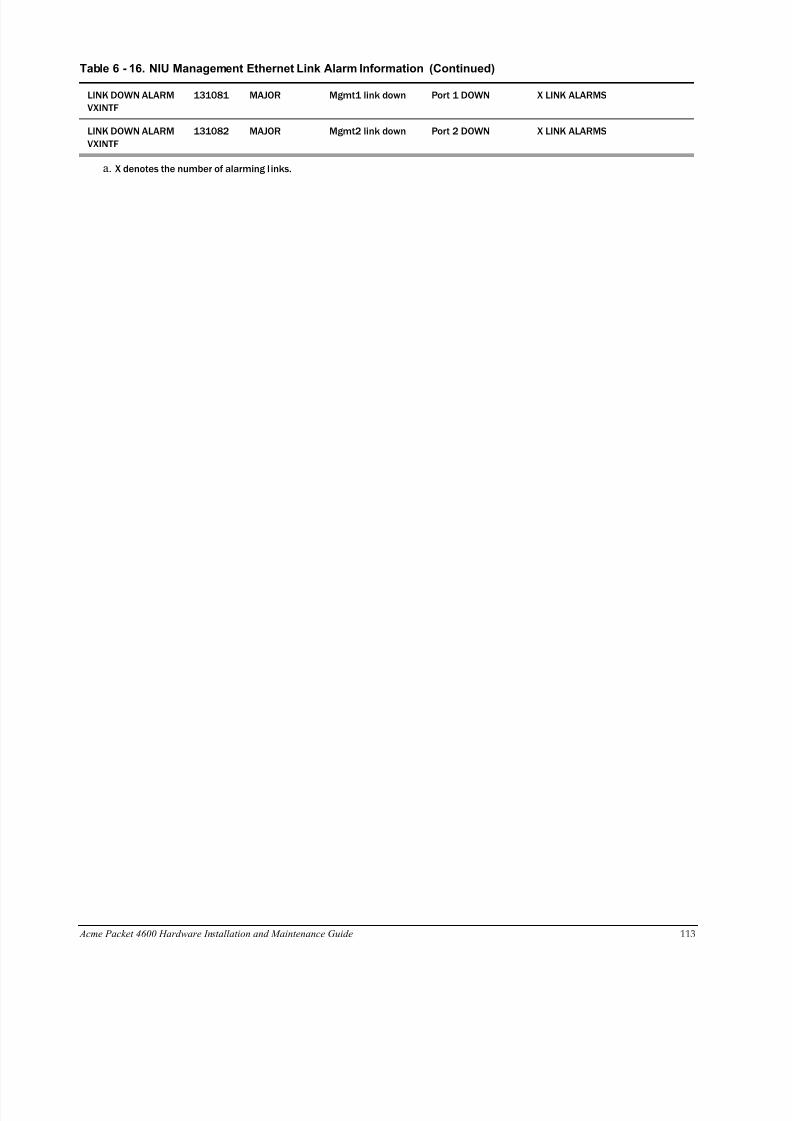
8/15/2019 Installation guide for ACME 4600
http://slidepdf.com/reader/full/installation-guide-for-acme-4600 115/132
Acme Packet 4600 Hardware Installation and Maintenance Guide 113
LINK DOWN ALARM
VXINTF
131081 MAJOR Mgmt1 link down Port 1 DOWN X LINK ALARMS
LINK DOWN ALARM
VXINTF
131082 MAJOR Mgmt2 link down Port 2 DOWN X LINK ALARMS
a. X denotes the number of alarming l inks.
Table 6 - 16. NIU Management Ethernet Link Alarm Information (Continued)

8/15/2019 Installation guide for ACME 4600
http://slidepdf.com/reader/full/installation-guide-for-acme-4600 116/132
114 Acme Packet 4600 Hardware Installation and Maintenance Guide
SFP Presence Alarms The following table lists the alarms that reflect when an SFP moduleis inserted or removed from an NIU.
Table 6 - 17. SFP Presence Alarm Information
Alarm Name
Alarm
ID
Alarm Severity
Cause s)
Example Log Message
Graphic Display
Message
SFP REMOVED GIGPORT 0 65568 CRITICAL S0P0 SFP Removed Slot 0 Port 0 SFP Removed X HW ALARMS:(where X is the
number of hard-
ware alarms
SFP INSERTED GIGPORT 0 65569 CRITICAL S0P0 SFP Inserted Slot 0 Port 0 SFP Inserted X HW ALARMS:
(where X is the
number of hard-
ware alarms
SFP REMOVED GIGPORT 1 65570 CRITICAL S0P1 SFP Removed Slot 0 Port 1 SFP Removed X HW ALARMS:
(where X is the
number of hard-
ware alarms
SFP INSERTED GIGPORT 1 65571 CRITICAL S0P1 SFP Inserted Slot 0 Port 1 SFP Inserted X HW ALARMS:
(where X is thenumber of hard-
ware alarms
SFP REMOVED GIGPORT 2 65572 CRITICAL S0P2 SFP Removed Slot 0 Port 2 SFP Removed X HW ALARMS:
(where X is the
number of hard-
ware alarms
SFP INSERTED GIGPORT 2 65573 CRITICAL S0P2 SFP Inserted Slot 0 Port 2 SFP Inserted X HW ALARMS:
(where X is the
number of hard-
ware alarms
SFP REMOVED GIGPORT 3 65574 CRITICAL S0P3 SFP Removed Slot 0 Port 3 SFP Removed X HW ALARMS:
(where X is the
number of hard-ware alarms
SFP INSERTED GIGPORT 3 65575 CRITICAL S0P3 SFP Inserted Slot 0 Port 3 SFP Inserted X HW ALARMS:
(where X is the
number of hard-
ware alarms
SFP REMOVED 10GIGPORT 4 65576 CRITICAL S0P4 SFP Removed Slot 0 Port 4 SFP Removed X HW ALARMS:
(where X is the
number of hard-
ware alarms
SFP INSERTED 10GIGPORT 4 65577 CRITICAL S0P4 SFP Inserted Slot 0 Port 4 SFP Inserted X HW ALARMS:
(where X is the
number of hard-
ware alarms
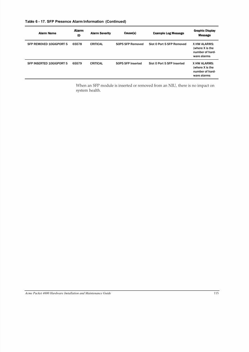
8/15/2019 Installation guide for ACME 4600
http://slidepdf.com/reader/full/installation-guide-for-acme-4600 117/132
Acme Packet 4600 Hardware Installation and Maintenance Guide 115
When an SFP module is inserted or removed from an NIU, there is no impact onsystem health.
SFP REMOVED 10GIGPORT 5 65578 CRITICAL S0P5 SFP Removed Slot 0 Port 5 SFP Removed X HW ALARMS:
(where X is the
number of hard-
ware alarms
SFP INSERTED 10GIGPORT 5 65579 CRITICAL S0P5 SFP Inserted Slot 0 Port 5 SFP Inserted X HW ALARMS:
(where X is the
number of hard-
ware alarms
Table 6 - 17. SFP Presence Alarm Information (Continued)
Alarm Name
Alarm
ID
Alarm Severity
Cause s)
Example Log Message
Graphic Display
Message

8/15/2019 Installation guide for ACME 4600
http://slidepdf.com/reader/full/installation-guide-for-acme-4600 118/132
116 Acme Packet 4600 Hardware Installation and Maintenance Guide

8/15/2019 Installation guide for ACME 4600
http://slidepdf.com/reader/full/installation-guide-for-acme-4600 119/132
Acme Packet 4600 Hardware Installation and Maintenance Guide 117
7 Specifications
IntroductionThis chapter provides information regarding the physical, electrical,environmental, and connector specifications of the Acme Packet 4600 System.
Environmental, Safety, and Regulatory Certifications
For information regarding safety and regulatory certifications applicable to the AcmePacket 4600, refer to the Acme Packet Platforms Safety and Compliance Guide.
Physical Specifications
Acme Packet 4600System ChassisSpecifications
This table lists the physical dimensions and weight of the Acme Packet 4600chassis.
Table 7 - 18. Acme Packet 4600 Physical Specifications
Specification Description
Height 1.72” (4.37 cm) (1U)
Width 17.10” (43.43 cm) (+ mounting ear width: 19” (43.18 cm))
Depth 20” (48.26 cm) (+ mounting slide bar depth)
Weight approximately 20.5 lbs (9.30 kg), fully loaded
AC Power SupplyPhysicalDimensions
This table lists the physical dimensions and weight of the Acme Packet 4600AC power supply.
Table 7 - 19. Acme Packet 4600 AC Power Supply Physical Dimensions
Specification Description
Height 1.575” (4.00 cm)
Width 2.146” (5.45 cm)
Depth 13.26” (33.68 cm)
Weight 2lbs., 5 oz. (1.05 kg)
Important: This equipment is intended for installation in locations whereNational Electrical Code (NEC) applies.
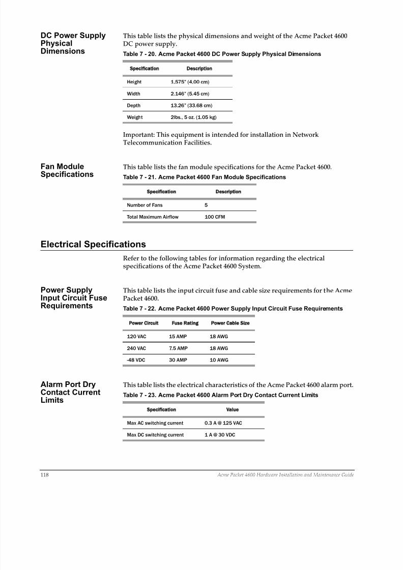
8/15/2019 Installation guide for ACME 4600
http://slidepdf.com/reader/full/installation-guide-for-acme-4600 120/132
118 Acme Packet 4600 Hardware Installation and Maintenance Guide
DC Power SupplyPhysicalDimensions
This table lists the physical dimensions and weight of the Acme Packet 4600DC power supply.
Table 7 - 20. Acme Packet 4600 DC Power Supply Physical Dimensions
Specification Description
Height 1.575” (4.00 cm)
Width 2.146” (5.45 cm)
Depth 13.26” (33.68 cm)
Weight 2lbs., 5 oz. (1.05 kg)
Important: This equipment is intended for installation in NetworkTelecommunication Facilities.
Fan ModuleSpecifications
This table lists the fan module specifications for the Acme Packet 4600.
Table 7 - 21. Acme Packet 4600 Fan Module Specifications
Specification Description
Number of Fans 5
Total Maximum Airflow 100 CFM
Electrical Specifications
Refer to the following tables for information regarding the electricalspecifications of the Acme Packet 4600 System.
Power Supply
Input Circuit FuseRequirements
This table lists the input circuit fuse and cable size requirements for the Acme
Packet 4600.Table 7 - 22. Acme Packet 4600 Power Supply Input Circuit Fuse Requirements
Power Circuit Fuse Rating Power Cable Size
120 VAC 15 AMP 18 AWG
240 VAC 7.5 AMP 18 AWG
-48 VDC 30 AMP 10 AWG
Alarm Port DryContact Current
Limits
This table lists the electrical characteristics of the Acme Packet 4600 alarm port.
Table 7 - 23. Acme Packet 4600 Alarm Port Dry Contact Current Limits
Specification Value
Max AC switching current 0.3 A @ 125 VAC
Max DC switching current 1 A @ 30 VDC
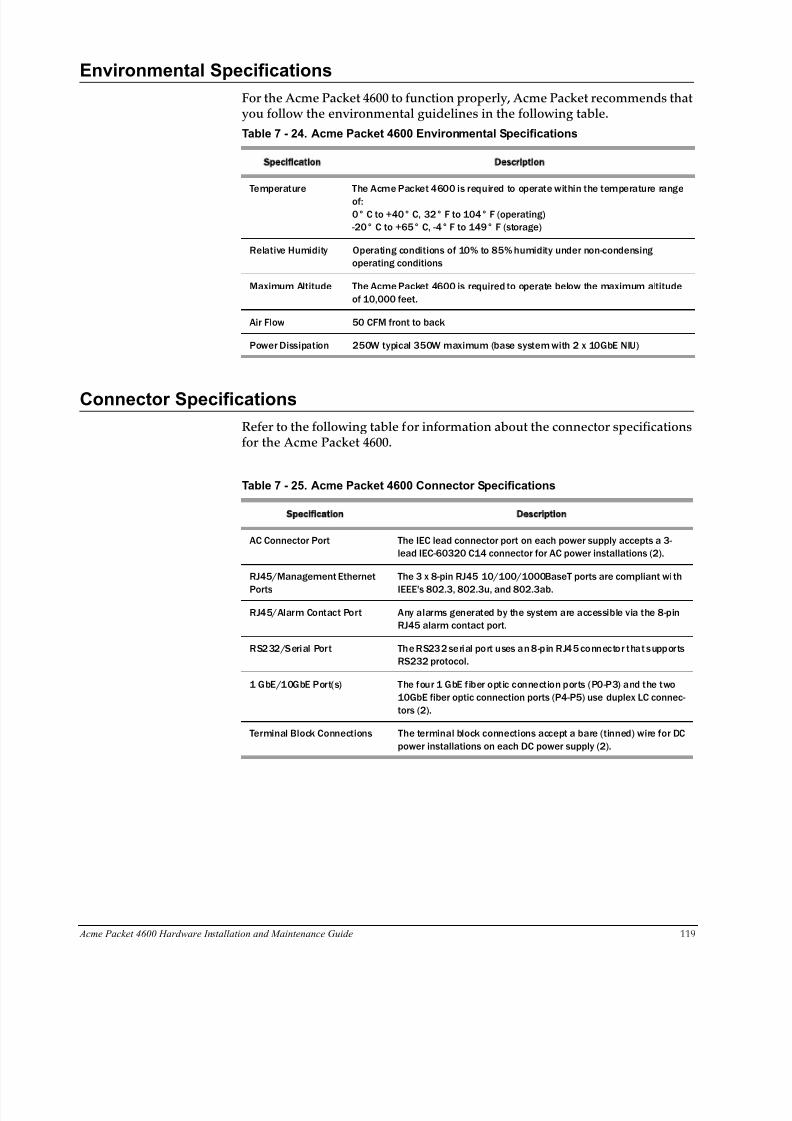
8/15/2019 Installation guide for ACME 4600
http://slidepdf.com/reader/full/installation-guide-for-acme-4600 121/132
Acme Packet 4600 Hardware Installation and Maintenance Guide 119
Environmental Specifications
For the Acme Packet 4600 to function properly, Acme Packet recommends thatyou follow the environmental guidelines in the following table.
Table 7 - 24. Acme Packet 4600 Environmental Specifications
Specification Description
Temperature The Acme Packet 4600 is required to operate within the temperature range
of:
0° C to +40° C, 32° F to 104° F (operating)
-20° C to +65° C, -4° F to 149° F (storage)
Relative Humidity Operating conditions of 10% to 85% humidity under non-condensing
operating conditions
Maximum Altitude The Acme Packet 4600 is required to operate below the maximum altitude
of 10,000 feet.
Air Flow 50 CFM front to back
Power Dissipation 250W typical 350W maximum (base system with 2 x 10GbE NIU)
Connector Specifications
Refer to the following table for information about the connector specificationsfor the Acme Packet 4600.
Table 7 - 25. Acme Packet 4600 Connector Specifications
Specification Description
AC Connector Port The IEC lead connector port on each power supply accepts a 3-
lead IEC-60320 C14 connector for AC power installations (2).
RJ45/Management Ethernet
Ports
The 3 x 8-pin RJ45 10/100/1000BaseT ports are compliant wi th
IEEE's 802.3, 802.3u, and 802.3ab.
RJ45/Alarm Contact Port Any alarms generated by the system are accessible via the 8-pin
RJ45 alarm contact port.
RS232/Serial Port The RS232 serial port uses an 8-pin RJ45 connector that supports
RS232 protocol.
1 GbE/10GbE Port(s) The four 1 GbE fiber optic connection ports (P0-P3) and the two
10GbE fiber optic connection ports (P4-P5) use duplex LC connec-
tors (2).
Terminal Block Connections The terminal block connections accept a bare (tinned) wire for DC
power installations on each DC power supply (2).
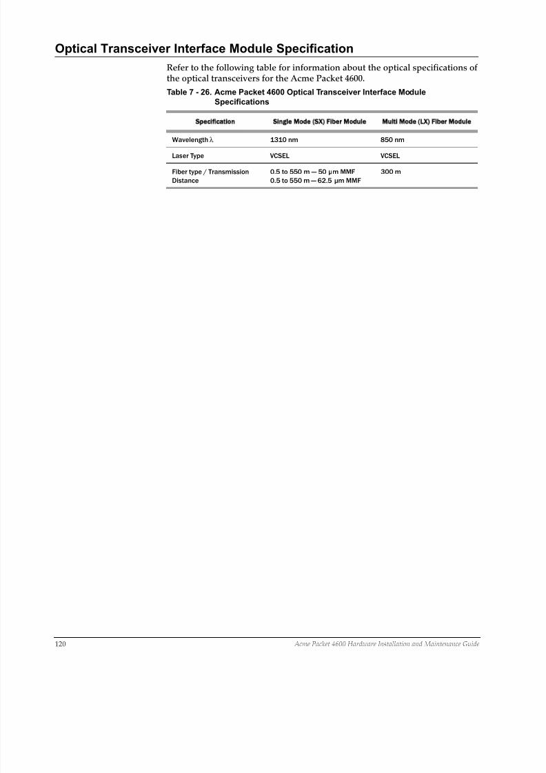
8/15/2019 Installation guide for ACME 4600
http://slidepdf.com/reader/full/installation-guide-for-acme-4600 122/132
120 Acme Packet 4600 Hardware Installation and Maintenance Guide
Optical Transceiver Interface Module Specification
Refer to the following table for information about the optical specifications ofthe optical transceivers for the Acme Packet 4600.
Table 7 - 26. Acme Packet 4600 Optical Transceiver Interface Module
Specifications
Specification Single Mode SX) Fiber Module Multi Mode LX) Fiber Module
Wavelength λ 1310 nm 850 nm
Laser Type VCSEL VCSEL
Fiber type / Transmission
Distance
0.5 to 550 m — 50 μm MMF
0.5 to 550 m — 62.5 μm MMF
300 m
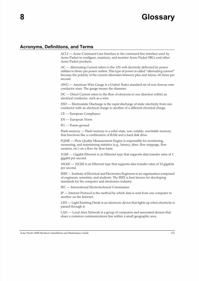
8/15/2019 Installation guide for ACME 4600
http://slidepdf.com/reader/full/installation-guide-for-acme-4600 123/132
Acme Packet 4600 Hardware Installation and Maintenance Guide 121
8 Glossary
Acronyms, Definitions, and Terms ACLI — Acme Command Line Interface is the command line interface used by Acme Packet to configure, maintain, and monitor Acme Packet SBCs and other Acme Packet products.
AC — Alternating Current refers to the 120-volt electricity delivered by powerutilities to three-pin power outlets. This type of power is called “alternating current”because the polarity of the current alternates between plus and minus, 60 times persecond.
AWG — American Wire Gauge is a United States standard set of non-ferrous wireconductor sizes. The gauge means the diameter.
DC — Direct Current refers to the flow of electrons in one direction within an
electrical conductor, such as a wire.
ESD — Electrostatic Discharge is the rapid discharge of static electricity from oneconductor with an electrical charge to another of a different electrical charge.
CE — European Compliance
EN — European Norm
FG — Frame ground
Flash memory — Flash memory is a solid-state, non-volatile, rewritable memorythat functions like a combination of RAM and a hard disk drive.
FQME — Flow Quality Measurement Engine is responsible for monitoring,measuring, and maintaining statistics (e.g., latency, jitter, flow stoppage, flow
creation, etc.) on a flow-by-flow basis.
1GbE — Gigabit Ethernet is an Ethernet type that supports data transfer rates of 1gigabit per second.
10GbE — 10GbE is an Ethernet type that supports data transfer rates of 10 gigabitsper second.
IEEE — Institute of Electrical and Electronics Engineers is an organization composedof engineers, scientists, and students. The IEEE is best known for developingstandards for the computer and electronics industry.
IEC — International Electrotechnical Commission
IP — Internet Protocol is the method by which data is sent from one computer to
another on the Internet.
LED — Light Emitting Diode is an electronic device that lights up when electricity ispassed through it.
LAN — Local Area Network is a group of computers and associated devices thatshare a common communications line within a small geographic area.

8/15/2019 Installation guide for ACME 4600
http://slidepdf.com/reader/full/installation-guide-for-acme-4600 124/132
122 Acme Packet 4600 Hardware Installation and Maintenance Guide
LOS — Loss of Signal occurs when the signal level falls below an acceptable level.LOS is a physical layer error and typically results in an alarm.
NIC — Network Interface Card is an expansion board you insert into a computer sothe computer can be connected to a network.
NIU — The NIU provides network connectivity for management, signaling, andmedia traffic to and from the Acme Packet 4600 System.
NVRAM — Non-volatile Random Access Memory is a type of memory that retains
its contents when power is turned off.
Optical Transceiver — The fiber connection to the Acme Packet 4600 System plugsinto an optical transceiver. Through this connection, light energy is converted intoelectrical energy.
PCMCIA — Personal Computer Memory Card International Association is anorganization consisting of approximately 500 companies that has developed astandard for small, credit-card sized devices (PC cards). This standard is designed forattaching input/output devices such as network adaptors, fax/modems, or harddrives to notebook computers.
Physical Interface Card — The physical interface card is synonymous with thenetwork interface cards on the Acme Packet 4600 System.
PROM — Programmable Read-only Memory is a memory chip on which data canonly be written once. A PROM is non-volatile; it is a memory chip on which data canbe written only once.
QoS — Quality of Service is a networking term that refers to the capability of anetwork to provide better service to selected network traffic over varioustechnologies.
RAM — Random Access Memory is a type of computer memory that can be accessedrandomly. RAM is the same as main memory.
RS-232 — Recommended Standard 232 is a standard interface approved by theElectronic Industries Association for connecting serial devices.
RJ45 — Registered Jack 45 is an eight-wire connector commonly used to connectcomputers onto a LAN.
SNMP — Simple Network Management Protocol is a set of protocols used formanaging complex networks and network devices.
SDRAM — Synchronous Dynamic Random Access Memory is a type of DRAM thatcan run at much higher clock speeds than conventional memory.
Telnet — Telnet is a standard terminal emulation program that allows remote loginand connection to systems/servers on a network. Telnet uses a single TCP/IPnetwork connection to provide this remote login, control, and communicationfunctionality.
TCP — Transmission Control Protocol provides a reliable stream delivery and virtual
connection service to applications through the use of sequenced acknowledgment with the retransmission of packets when necessary.
UPS — Uninterruptible Power Supply is a power supply that can run off of a backupbattery when primary power is lost.
UDP — User Datagram Protocol provides a simple, but unreliable message servicefor transaction-oriented services. Each UDP header carries both a source port

8/15/2019 Installation guide for ACME 4600
http://slidepdf.com/reader/full/installation-guide-for-acme-4600 125/132
Acme Packet 4600 Hardware Installation and Maintenance Guide 123
identifier and a destination port identifier, allowing high-level protocols to targetspecific applications and services among hosts.
VFD — Vacuum Fluorescent Display is used on the graphic display window of the Acme Packet 4600 System chassis’s front control panel.
VLAN — Virtual Local Area Network refers to a network of computers areconnected to a single physical segment of a wire but behave as if they are connectedto the physically diverse LANs.
VAC — Volts Alternating Current
VDC — Volts Direct Current
VCCI — Voluntary Control Council for Information Technology Equipment (Japan)
WAN—Wide Area Network is a computer network that spans a relatively largegeographical area. Typically, a WAN consists of two or more LANs.

8/15/2019 Installation guide for ACME 4600
http://slidepdf.com/reader/full/installation-guide-for-acme-4600 126/132
124 Acme Packet 4600 Hardware Installation and Maintenance Guide
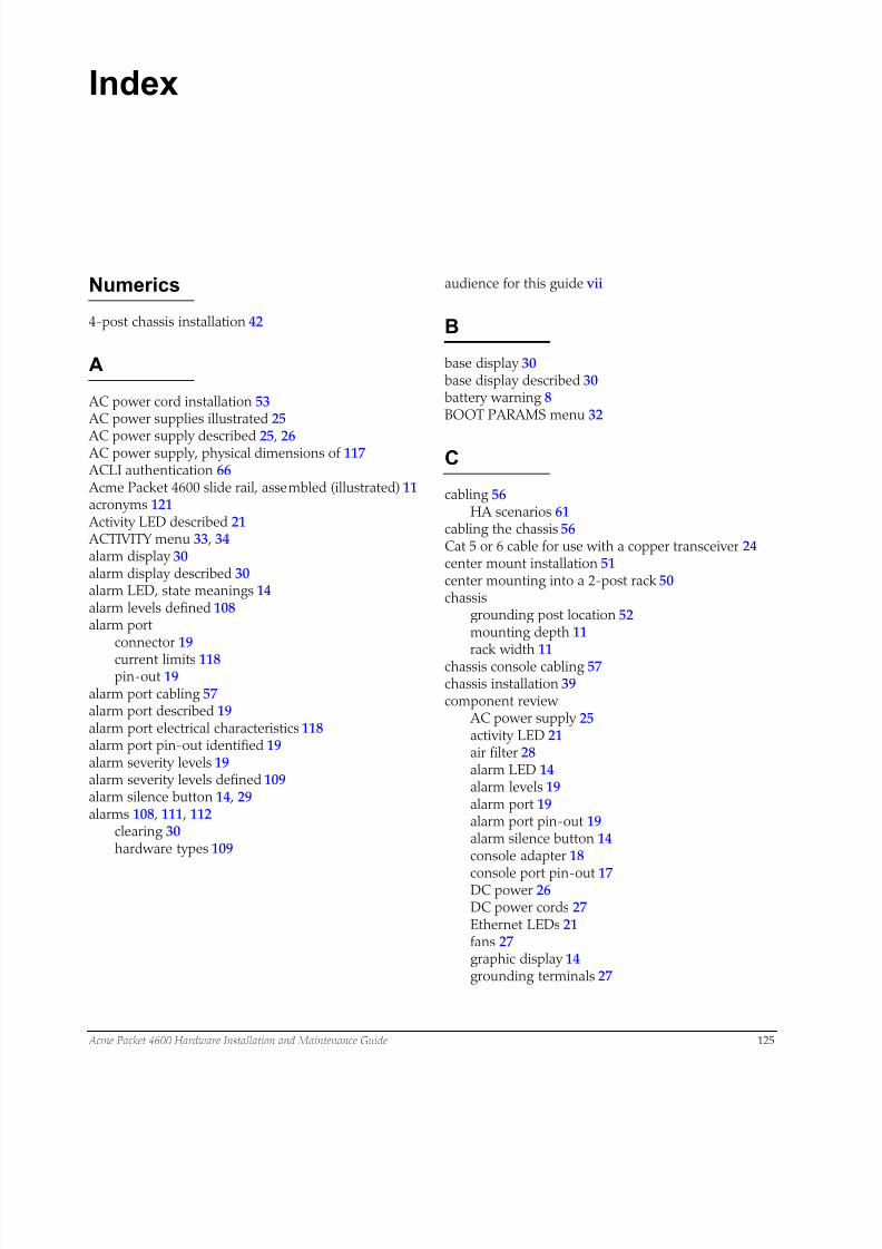
8/15/2019 Installation guide for ACME 4600
http://slidepdf.com/reader/full/installation-guide-for-acme-4600 127/132
Acme Packet 4600 Hardware Installation and Maintenance Guide 125
Index
Numerics
4-post chassis installation 42
A
AC power cord installation 53 AC power supplies illustrated 25
AC power supply described 25 , 26 AC power supply, physical dimensions of 117 ACLI authentication 66 Acme Packet 4600 slide rail, assembled (illustrated) 11acronyms 121 Activity LED described 21 ACTIVITY menu 33 , 34alarm display 30alarm display described 30alarm LED, state meanings 14alarm levels defined 108alarm port
connector 19
current limits 118pin-out 19
alarm port cabling 57alarm port described 19alarm port electrical characteristics 118alarm port pin-out identified 19alarm severity levels 19alarm severity levels defined 109alarm silence button 14 , 29alarms 108 , 111 , 112
clearing 30hardware types 109
audience for this guide vii
B
base display 30base display described 30battery warning 8BOOT PARAMS menu 32
C
cabling 56HA scenarios 61
cabling the chassis 56Cat 5 or 6 cable for use with a copper transceiver 24center mount installation 51center mounting into a 2-post rack 50chassis
grounding post location 52mounting depth 11
rack width 11chassis console cabling 57chassis installation 39component review
AC power supply 25activity LED 21air filter 28alarm LED 14alarm levels 19alarm port 19alarm port pin-out 19alarm silence button 14console adapter 18
console port pin-out 17DC power 26DC power cords 27Ethernet LEDs 21fans 27graphic display 14grounding terminals 27
8/15/2019 Installation guide for ACME 4600
http://slidepdf.com/reader/full/installation-guide-for-acme-4600 128/132
126 Acme Packet 4600 Hardware Installation and Maintenance Guide
intake fans 15link LED 21navigation buttons 14network management ports 20NIU 15power components 24power supply redundancy 25rear panel 15
reset pushbutton 14signaling and media interfaces 21system power switch 16USB port 20
connector specifications 119console adapter 19console adapter described 18console cable 19console connection, creating 65console connection, creating a 65console port
uses 17console port cabling 57
console port described 17console port, connecting to 56console port, pin-out described 17console session 65control panel
front 14rear 15
cooling components 27air inlets 27maintenance 103
cooling components, cleaning 104cooling components, maintaining 103CPU described 13
D
DC power cord installation 55DC power supplies illustrated 25DC power supply described 26DC power supply, physical dimensions of 118default password 66definitions 121display modes described 30display output for HA nodes 34
E
electrical safety precautions 8ENVIRONMENT menu 34environmental guidelines 119environmental guidelines for installation 38environmental precaution 7environmental sensor alarm information 110environmental, safety, and regulatory certifications 7 ,117equipment rack
safety 39equipment rack hardware described 11ESD precautions 9ESD safety 9Ethernet LED described 21Ethernet port cabling 57
Ethernet portscable specification 21recommended cables 21
F
fan modulereplacement 101 , 102
fan module installation 51fan module specifications 118fan module, precaution 7fan speed 27fan speed alarm information 109fan, installing 102fan, replacing 101fan/filter maintenance 101fans described, chassis cooling 27fans, intake 15fiber optic cable installation 59fiber optic cable, for use with a multi mode SX trans-
8/15/2019 Installation guide for ACME 4600
http://slidepdf.com/reader/full/installation-guide-for-acme-4600 129/132
Acme Packet 4600 Hardware Installation and Maintenance Guide 127
ceiver 23fiber optic cable, for use with a single mode LX trans-ceiver 24fiber optic cable, precaution 7flip-down door
console port 14navigation buttons 14reset button 14
forcing an Acme Packet 4600 in standby state 71front bezel, removing 104front control panel described 13front control panel illustrated 14front panel
components 13front-mount installation
hardware 11
G
graphic display 14 , 29
activity menu 33alarm display 30base display 30bootparams menu 32buttons 29environment menu 34HA State 35interface menu 31navigation 29system menu 32top menu 30
graphic display button functions 29graphic display described 29
graphic display menus about 30graphic display modes 30graphic display output for HA nodes 35ground cable installation 52ground installation 51grounding
failure 52grounding post 52
H
HA cabling 61
HA nodes, display output for 34HA state determination 71HA switchover 71hardware and environmental alarms 109hardware temperature alarm information 109hot-swappable parts
fan module 101
optical transceiver 106power supplies 77
I
input circuit fuse and cable size requirements 118installation 63
AC power cord 53 , 55fan module 51grounding cable 51power cables 51requirements
environmental 38mounting 39power 38
tools and partsrecommended 38required 37
installation guidelines 39installation safety guidelines 39
installing a chassis into a 4-post rack 48installing chassis flanges and slide rails 47installing chassis into a 2-post rack 51installing in a 4-post chassis cabinet 42installing into a 2-post rack 50installing into a square-hole rack 45installing slide rails 42installing the chassis 39installing the chassis into a tapped-hole rack 43INTERFACE menu 31introduction to the Acme Packet 4600 vii , 7
LLEDs
alarm 14Link LED described 21logging in 66logging in to the Acme Packet 4600 66
M
management interface. See also Ethernet portsmedia and signaling network interface cabling 58media cable types 23media cabling for HA nodes 63media Ethernet link alarm information 111menu categories 31menu options 31mounting guidelines 39mounting hardware 11 , 40
chassis section slide 12
8/15/2019 Installation guide for ACME 4600
http://slidepdf.com/reader/full/installation-guide-for-acme-4600 130/132
128 Acme Packet 4600 Hardware Installation and Maintenance Guide
mounting slides as shipped 11mounting hardware described 11mounting installation
AC power cord installation 53center mount installation 50chassis installation into a 4-post equipment rack
48DC power cord installation 55
equipment rack slide rails 42fan module installation 51ground cable installation 52ground installation 51installing chassis rail slides 47mounting hardware 40mounting options 39overview 39power cable installation 51slide rail installation, square-hole rack 45slide rails 43unpacking the Acme Packet 4600 40
mounting options for installing the chassis 39
N
navigation buttons 14 , 29network interface unit
slots 15network management ports described 20NIU
slot numbering 18NIU alarm information 111NIU described 15NIU management Ethernet port alarm information 112
NIU, replacing 74
O
optic cablehanding 59
optical transceivermaintenance 106replacement 107
optical transceiver specifications 120optical transceiver, installing 107optical transceiver, removal/replacement 106
P
physical dimensions and weight 117physical interface card
ejection lever 81removal 79
power cycling 71power guidelines for installation 38power redundancy explained 25power supplies
AC 25DC 26numbering 25on-off switch 27
redundancy 25removal 77single usage 25
power supplies described 24power supply alarm information 110power supply components
AC power cord 26 , 53 , 55DC power cord 27
power supply removal and replacement 77powering the Acme Packet 4600 66pre-installation guidelines 38
Rrear panel cabling 61rear panel components 15rebooting 70rebooting the Acme Packet 4600 70rejecting incoming calls 69removing front bezel 104removing the chassis 75replacing a fan 101reset button 14reset pushbutton 14resetting system 14 , 70
resetting the system 70RETURN 34
S
safety guidelines 39safety precautions 7safety precautions, general 7safety requirements 39serial adapter. See also console adapterserial port
flow control 17
serial port, connecting to 57SFP presence alarm information 114SFP+ identification 22shipping box
accessory kit 37unpacking 40

8/15/2019 Installation guide for ACME 4600
http://slidepdf.com/reader/full/installation-guide-for-acme-4600 131/132
Acme Packet 4600 Hardware Installation and Maintenance Guide 129
shipping contents 37shut down procedure 69
rejecting incoming calls 69shutting down 69shutting down the Acme Packet 4600 69signaling and media interfaces described 21signaling and media interfaces identified and described21
signaling and media port, connection to fiber optic ca-bles 59signaling and media port, connection to GigE coppercables 58specifications
AC power supply 117alarm port 118connectors 119DC power supply 118environmental 119fan module 118optical transceiver 120physical 117
standby HA node, forcing 72standby mode 71standby mode, entering 71system maintenance, precaution 7SYSTEM menu 32system power switch 16system reset 70
T
terminal connection 65terms 121
tools required 37
U
unpacking the Acme Packet 4600 40USB port described 20
V
ventilation maintenance 101 voltage alarm information 110
W
wancom port. See also Ethernet ports wiring. See cabling

8/15/2019 Installation guide for ACME 4600
http://slidepdf.com/reader/full/installation-guide-for-acme-4600 132/132